EP4063626A1 - Module de mélange de gaz d'échappement / réactif - Google Patents
Module de mélange de gaz d'échappement / réactif Download PDFInfo
- Publication number
- EP4063626A1 EP4063626A1 EP22157861.0A EP22157861A EP4063626A1 EP 4063626 A1 EP4063626 A1 EP 4063626A1 EP 22157861 A EP22157861 A EP 22157861A EP 4063626 A1 EP4063626 A1 EP 4063626A1
- Authority
- EP
- European Patent Office
- Prior art keywords
- mixing
- exhaust gas
- duct
- reactant
- junction
- Prior art date
- Legal status (The legal status is an assumption and is not a legal conclusion. Google has not performed a legal analysis and makes no representation as to the accuracy of the status listed.)
- Granted
Links
Images


Classifications
-
- F—MECHANICAL ENGINEERING; LIGHTING; HEATING; WEAPONS; BLASTING
- F01—MACHINES OR ENGINES IN GENERAL; ENGINE PLANTS IN GENERAL; STEAM ENGINES
- F01N—GAS-FLOW SILENCERS OR EXHAUST APPARATUS FOR MACHINES OR ENGINES IN GENERAL; GAS-FLOW SILENCERS OR EXHAUST APPARATUS FOR INTERNAL-COMBUSTION ENGINES
- F01N3/00—Exhaust or silencing apparatus having means for purifying, rendering innocuous, or otherwise treating exhaust
- F01N3/08—Exhaust or silencing apparatus having means for purifying, rendering innocuous, or otherwise treating exhaust for rendering innocuous
- F01N3/10—Exhaust or silencing apparatus having means for purifying, rendering innocuous, or otherwise treating exhaust for rendering innocuous by thermal or catalytic conversion of noxious components of exhaust
- F01N3/18—Exhaust or silencing apparatus having means for purifying, rendering innocuous, or otherwise treating exhaust for rendering innocuous by thermal or catalytic conversion of noxious components of exhaust characterised by methods of operation; Control
- F01N3/20—Exhaust or silencing apparatus having means for purifying, rendering innocuous, or otherwise treating exhaust for rendering innocuous by thermal or catalytic conversion of noxious components of exhaust characterised by methods of operation; Control specially adapted for catalytic conversion
- F01N3/206—Adding periodically or continuously substances to exhaust gases for promoting purification, e.g. catalytic material in liquid form, NOx reducing agents
- F01N3/2066—Selective catalytic reduction [SCR]
-
- F—MECHANICAL ENGINEERING; LIGHTING; HEATING; WEAPONS; BLASTING
- F01—MACHINES OR ENGINES IN GENERAL; ENGINE PLANTS IN GENERAL; STEAM ENGINES
- F01N—GAS-FLOW SILENCERS OR EXHAUST APPARATUS FOR MACHINES OR ENGINES IN GENERAL; GAS-FLOW SILENCERS OR EXHAUST APPARATUS FOR INTERNAL-COMBUSTION ENGINES
- F01N3/00—Exhaust or silencing apparatus having means for purifying, rendering innocuous, or otherwise treating exhaust
- F01N3/08—Exhaust or silencing apparatus having means for purifying, rendering innocuous, or otherwise treating exhaust for rendering innocuous
- F01N3/10—Exhaust or silencing apparatus having means for purifying, rendering innocuous, or otherwise treating exhaust for rendering innocuous by thermal or catalytic conversion of noxious components of exhaust
- F01N3/24—Exhaust or silencing apparatus having means for purifying, rendering innocuous, or otherwise treating exhaust for rendering innocuous by thermal or catalytic conversion of noxious components of exhaust characterised by constructional aspects of converting apparatus
- F01N3/28—Construction of catalytic reactors
- F01N3/2892—Exhaust flow directors or the like, e.g. upstream of catalytic device
-
- F—MECHANICAL ENGINEERING; LIGHTING; HEATING; WEAPONS; BLASTING
- F01—MACHINES OR ENGINES IN GENERAL; ENGINE PLANTS IN GENERAL; STEAM ENGINES
- F01N—GAS-FLOW SILENCERS OR EXHAUST APPARATUS FOR MACHINES OR ENGINES IN GENERAL; GAS-FLOW SILENCERS OR EXHAUST APPARATUS FOR INTERNAL-COMBUSTION ENGINES
- F01N13/00—Exhaust or silencing apparatus characterised by constructional features
- F01N13/08—Other arrangements or adaptations of exhaust conduits
-
- F—MECHANICAL ENGINEERING; LIGHTING; HEATING; WEAPONS; BLASTING
- F01—MACHINES OR ENGINES IN GENERAL; ENGINE PLANTS IN GENERAL; STEAM ENGINES
- F01N—GAS-FLOW SILENCERS OR EXHAUST APPARATUS FOR MACHINES OR ENGINES IN GENERAL; GAS-FLOW SILENCERS OR EXHAUST APPARATUS FOR INTERNAL-COMBUSTION ENGINES
- F01N13/00—Exhaust or silencing apparatus characterised by constructional features
- F01N13/08—Other arrangements or adaptations of exhaust conduits
- F01N13/10—Other arrangements or adaptations of exhaust conduits of exhaust manifolds
- F01N13/107—More than one exhaust manifold or exhaust collector
-
- F—MECHANICAL ENGINEERING; LIGHTING; HEATING; WEAPONS; BLASTING
- F01—MACHINES OR ENGINES IN GENERAL; ENGINE PLANTS IN GENERAL; STEAM ENGINES
- F01N—GAS-FLOW SILENCERS OR EXHAUST APPARATUS FOR MACHINES OR ENGINES IN GENERAL; GAS-FLOW SILENCERS OR EXHAUST APPARATUS FOR INTERNAL-COMBUSTION ENGINES
- F01N2240/00—Combination or association of two or more different exhaust treating devices, or of at least one such device with an auxiliary device, not covered by indexing codes F01N2230/00 or F01N2250/00, one of the devices being
- F01N2240/20—Combination or association of two or more different exhaust treating devices, or of at least one such device with an auxiliary device, not covered by indexing codes F01N2230/00 or F01N2250/00, one of the devices being a flow director or deflector
-
- F—MECHANICAL ENGINEERING; LIGHTING; HEATING; WEAPONS; BLASTING
- F01—MACHINES OR ENGINES IN GENERAL; ENGINE PLANTS IN GENERAL; STEAM ENGINES
- F01N—GAS-FLOW SILENCERS OR EXHAUST APPARATUS FOR MACHINES OR ENGINES IN GENERAL; GAS-FLOW SILENCERS OR EXHAUST APPARATUS FOR INTERNAL-COMBUSTION ENGINES
- F01N2260/00—Exhaust treating devices having provisions not otherwise provided for
- F01N2260/14—Exhaust treating devices having provisions not otherwise provided for for modifying or adapting flow area or back-pressure
-
- F—MECHANICAL ENGINEERING; LIGHTING; HEATING; WEAPONS; BLASTING
- F01—MACHINES OR ENGINES IN GENERAL; ENGINE PLANTS IN GENERAL; STEAM ENGINES
- F01N—GAS-FLOW SILENCERS OR EXHAUST APPARATUS FOR MACHINES OR ENGINES IN GENERAL; GAS-FLOW SILENCERS OR EXHAUST APPARATUS FOR INTERNAL-COMBUSTION ENGINES
- F01N2470/00—Structure or shape of exhaust gas passages, pipes or tubes
- F01N2470/30—Tubes with restrictions, i.e. venturi or the like, e.g. for sucking air or measuring mass flow
-
- F—MECHANICAL ENGINEERING; LIGHTING; HEATING; WEAPONS; BLASTING
- F01—MACHINES OR ENGINES IN GENERAL; ENGINE PLANTS IN GENERAL; STEAM ENGINES
- F01N—GAS-FLOW SILENCERS OR EXHAUST APPARATUS FOR MACHINES OR ENGINES IN GENERAL; GAS-FLOW SILENCERS OR EXHAUST APPARATUS FOR INTERNAL-COMBUSTION ENGINES
- F01N2610/00—Adding substances to exhaust gases
- F01N2610/02—Adding substances to exhaust gases the substance being ammonia or urea
-
- F—MECHANICAL ENGINEERING; LIGHTING; HEATING; WEAPONS; BLASTING
- F01—MACHINES OR ENGINES IN GENERAL; ENGINE PLANTS IN GENERAL; STEAM ENGINES
- F01N—GAS-FLOW SILENCERS OR EXHAUST APPARATUS FOR MACHINES OR ENGINES IN GENERAL; GAS-FLOW SILENCERS OR EXHAUST APPARATUS FOR INTERNAL-COMBUSTION ENGINES
- F01N2610/00—Adding substances to exhaust gases
- F01N2610/08—Adding substances to exhaust gases with prior mixing of the substances with a gas, e.g. air
-
- F—MECHANICAL ENGINEERING; LIGHTING; HEATING; WEAPONS; BLASTING
- F01—MACHINES OR ENGINES IN GENERAL; ENGINE PLANTS IN GENERAL; STEAM ENGINES
- F01N—GAS-FLOW SILENCERS OR EXHAUST APPARATUS FOR MACHINES OR ENGINES IN GENERAL; GAS-FLOW SILENCERS OR EXHAUST APPARATUS FOR INTERNAL-COMBUSTION ENGINES
- F01N2610/00—Adding substances to exhaust gases
- F01N2610/10—Adding substances to exhaust gases the substance being heated, e.g. by heating tank or supply line of the added substance
- F01N2610/102—Adding substances to exhaust gases the substance being heated, e.g. by heating tank or supply line of the added substance after addition to exhaust gases, e.g. by a passively or actively heated surface in the exhaust conduit
-
- Y—GENERAL TAGGING OF NEW TECHNOLOGICAL DEVELOPMENTS; GENERAL TAGGING OF CROSS-SECTIONAL TECHNOLOGIES SPANNING OVER SEVERAL SECTIONS OF THE IPC; TECHNICAL SUBJECTS COVERED BY FORMER USPC CROSS-REFERENCE ART COLLECTIONS [XRACs] AND DIGESTS
- Y02—TECHNOLOGIES OR APPLICATIONS FOR MITIGATION OR ADAPTATION AGAINST CLIMATE CHANGE
- Y02T—CLIMATE CHANGE MITIGATION TECHNOLOGIES RELATED TO TRANSPORTATION
- Y02T10/00—Road transport of goods or passengers
- Y02T10/10—Internal combustion engine [ICE] based vehicles
- Y02T10/12—Improving ICE efficiencies
Definitions
- the present invention relates to an exhaust gas/reactant mixing assembly, which is used to produce a thorough mixing of exhaust gas and reactant injected into the exhaust gas in an exhaust system of an internal combustion engine, in particular in a vehicle.
- mixing elements are generally used in the exhaust gas flow downstream of a reactant delivery unit in order to generate turbulence in the exhaust gas flow, which supports the thorough mixing of exhaust gas and reactant injected into it.
- the mixing duct be formed in a mixing duct housing with a mixing duct housing base and a mixing duct housing peripheral wall, and that at least one, preferably every inlet duct section be in the area of the Mixing channel housing peripheral wall and / or in the area of the mixing channel housing floor is open to the mixing channel.
- at least two junction duct sections are open to the mixing duct at circumferential regions of the mixing duct housing circumferential wall that are essentially opposite one another with respect to the mixing duct longitudinal axis.
- the reactant delivery unit can be provided on the mixing duct housing floor and/or a Be oriented reactant main delivery direction of the reactant delivery unit essentially in the direction of the mixing channel longitudinal axis.
- Intensive turbulence in the mixing duct can be further supported by the fact that in at least one, preferably every, junction duct section, an exhaust gas main outflow direction of exhaust gas flowing out of the junction duct section into the mixing duct has a flow direction component that is essentially tangential to the longitudinal axis of the mixing duct, and/or that at least one, preferably each junction duct section, an exhaust gas main outflow direction of exhaust gas flowing out of the junction duct section into the mixing duct lies essentially in a plane orthogonal to the longitudinal axis of the mixing duct. It should be pointed out in this context that such a main outflow direction can correspond, for example, to the main flow direction in the area of a central flow thread of a respective junction channel section.
- An exhaust gas main inflow direction in the exhaust gas supply duct can be essentially orthogonal to the longitudinal axis of the mixing duct. A substantially angled structure is thus achieved, which can support integration into other system areas of a vehicle.
- an exhaust gas main inflow direction in the exhaust gas supply duct can be essentially parallel to the longitudinal axis of the mixing duct.
- a slender structure that is elongated in the direction of the longitudinal axis of the mixing channel is thus obtained.
- the exhaust gas feed duct can essentially be formed in an exhaust gas feed duct housing with an exhaust gas feed duct housing base and an exhaust gas feed duct peripheral wall and a plurality of junction line areas starting from the exhaust gas feed duct housing bottom and/or the exhaust gas feed duct peripheral wall, with a junction duct section being formed in each junction line region.
- the exhaust gas/reactant mixing assembly constructed according to the invention efficiently mixes exhaust gas and reactant by generating turbulence in the exhaust gas by means of the flow guide, there is no need to arrange one or more mixing elements in the mixing channel.
- the invention also relates to an exhaust system for an internal combustion engine, comprising an exhaust gas/reactant mixing assembly constructed according to the invention.
- an SCR catalytic converter arrangement can be provided downstream of the mixing channel.
- At least one exhaust gas treatment unit can be provided upstream of the exhaust gas supply duct and/or in the exhaust gas supply duct.
- the at least one exhaust gas treatment unit can comprise a catalytic converter arrangement and/or a particle filter arrangement.
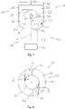
- Figures 1 to 4 Figure 12 shows a first embodiment of an exhaust gas/reactant mixing assembly 10 in which exhaust gas emitted from an internal combustion engine is mixed with reactant R injected therein.
- the illustrated exhaust gas/reactant mixing assembly 10 includes an exhaust gas supply duct housing, generally designated 12, and an adjoining mixing duct housing, generally designated 14.
- the exhaust gas feed duct housing 12 comprises an exhaust gas feed duct peripheral wall 16, which is configured essentially cylindrically, for example, and an exhaust gas feed duct housing base 18 adjoining the exhaust gas feed duct peripheral wall 16 16 enclosed area exhaust gas emitted by an internal combustion engine in the direction of a main exhaust gas flow direction Z on the exhaust gas supply channel housing floor 18 to.
- junction line regions 22 , 24 extend from the exhaust gas supply duct housing floor 18 .
- junction channel section 26 In each of the junction line areas 22, 24 there is a junction channel section 26, 28 a junction duct region, generally designated 30, of the exhaust gas supply duct 20 is formed.
- the mixing duct housing 14 comprises a mixing duct housing peripheral wall 32, which is of essentially cylindrical design and extends in the direction of a mixing duct longitudinal axis L, and a mixing duct housing bottom 34 adjoining this in an axial end region.
- a mixing duct 36 which extends essentially in a straight line educated.
- the two junction line regions 22 , 24 of the exhaust gas supply duct housing 12 adjoin the mixing duct housing 14 in the region of the mixing duct housing peripheral wall 32 , for example directly adjoining the mixing duct housing floor 34 .
- each of the two junction channel sections 26 , 28 provided in the junction line regions 22 , 24 opens essentially in the region of the mixing channel housing peripheral wall 32 into the mixing channel 36 delimited by the latter.
- the two junction line regions 22, 24 run or connect to the mixing channel housing peripheral wall 32 in such a way that they are offset transversely to the mixing channel longitudinal axis L with respect to one another.
- exhaust gas streams exiting from the two junction duct sections 26, 28 each have a main exhaust gas outflow direction A 1 or A 2 , which is offset transversely to the longitudinal axis L of the mixing duct or runs essentially tangentially with respect to it or a substantial have the mixing channel longitudinal axis L tangentially oriented flow direction component.
- such an exhaust gas main outflow direction A 1 or A 2 can approximately correspond to the main flow direction or can be defined by a main outflow direction which an exhaust gas flow flowing through a respective junction duct section 26 or 28 in the region of the central flow path of a respective junction duct section 26 and 28 respectively.
- the junction duct sections 26, 28 essentially adjoin the circumferential wall 32 of the mixing duct in the same area, the two main exhaust gas outflow directions A 1 , A 2 or the central flow threads that define them with their course, for example, are also located in an example through the drawing level of 3 defined plane that is essentially orthogonal to the longitudinal axis L of the mixing channel.
- a reactant dispensing unit 38 also generally referred to as an injector, is provided on the mixing channel housing base 34, for example centrally to the mixing channel longitudinal axis L. This releases the reactant R, for example in the form of a spray cone, in a main reactant release direction H along the longitudinal axis L of the mixing channel into the mixing channel 36 .
- the Figures 1 to 4 show that at the transition from the exhaust gas supply duct 20 to the mixing duct 36, there is a basic flow deflection of about 90°, since the exhaust gas main inflow direction Z in the exhaust gas supply duct 20 is oriented approximately orthogonally to the longitudinal axis L of the mixing duct.
- the exhaust gas/reactant mixing assembly 10 thus has a substantially angled structure.
- FIG. 5 to 8 An alternative embodiment, particularly with regard to this aspect, is Figures 5 to 8 shown.
- Components or system areas, which previously with reference to the Figures 1 to 4 correspond to the components or system areas described are denoted by the same reference symbols.
- the exhaust gas feed duct housing 12 is arranged essentially in the axial extension of the mixing duct housing 14, so that, for example, the exhaust gas feed duct housing peripheral wall 16 is positioned essentially coaxially with the mixing duct peripheral wall 32.
- the junction line areas 22, 24, which essentially start from the exhaust gas feed duct housing base 18, extend essentially in the direction of the mixing duct longitudinal axis L away from the exhaust gas feed duct housing base 18 towards the mixing duct housing 14 and adjoin the mixing duct housing peripheral wall 32 in end areas which are guided radially inwards with respect to the longitudinal axis L of the mixing channel, in areas that are essentially diametrically opposite one another.
- the exhaust gas routed through the junction duct sections 26, 28 formed in the junction line regions 22, 24 flows in the respective main exhaust gas outflow direction A 1 , A 2 in the direction of the mixing duct 36, which is offset laterally with respect to the longitudinal axis L of the mixing duct or is in the Substantially tangentially and oppositely directed.
- the exhaust gas streams flowing through the two junction duct sections are introduced into the mixing duct 36 essentially in the same axial region, so that a turbulent flow is also efficiently generated here, which also entrains the reactant introduced into the mixing duct 36 in the main reactant release direction H and leads to the mixing effect described above.
- the 7 illustrates in a conceptual manner the incorporation of such an exhaust/reactant mixing assembly 10 into an exhaust system, generally designated 42 .
- an exhaust system 42 Downstream of the mixing duct 36 or the mixing duct housing 14, this comprises an SCR catalytic converter arrangement 44, in which the proportion of nitrogen oxides in the exhaust gas is reduced by converting the reactant.
- the exhaust system 42 may further include one or more dispensing action units 46 upstream of the exhaust/reactant mixing assembly 10 .
- Such an exhaust gas treatment unit 46 can be designed, for example, as a catalytic converter arrangement, in particular a diesel oxidation catalytic converter arrangement.
- the integration of a particle filter arrangement designed as well Exhaust treatment unit 46 in such an exhaust system 42 upstream of the exhaust/reactant mixing assembly 10 is possible.
- such an exhaust gas treatment unit 46 can also be inserted into the exhaust gas feed duct housing 12, in particular the volume area surrounded by the exhaust gas feed duct peripheral wall 16, or positioned in an engaging manner.
- junction channel sections 26, 28 are particularly advantageous due to the particularly efficient generation of a turbulent flow due to the comparatively large radial distance to the mixing channel longitudinal axis L, it can slim design, it may be advantageous to alternatively or additionally connect the junction line regions 22 , 24 providing the junction channel sections 26 , 28 to the mixing channel housing 14 in the region of the mixing channel housing floor 34 . Part or all of the exhaust gas exiting the respective junction duct sections 26, 28 then enters the mixing duct 36 in the area of the mixing duct housing base 34, i.e. closer to the longitudinal axis L of the mixing duct.
Landscapes
- Engineering & Computer Science (AREA)
- Chemical & Material Sciences (AREA)
- Chemical Kinetics & Catalysis (AREA)
- Combustion & Propulsion (AREA)
- Mechanical Engineering (AREA)
- General Engineering & Computer Science (AREA)
- Health & Medical Sciences (AREA)
- Toxicology (AREA)
- Exhaust Gas After Treatment (AREA)
Applications Claiming Priority (1)
| Application Number | Priority Date | Filing Date | Title |
|---|---|---|---|
| DE102021107463.0A DE102021107463A1 (de) | 2021-03-25 | 2021-03-25 | Abgas/Reaktionsmittel-Mischbaugruppe |
Publications (2)
| Publication Number | Publication Date |
|---|---|
| EP4063626A1 true EP4063626A1 (fr) | 2022-09-28 |
| EP4063626B1 EP4063626B1 (fr) | 2025-08-20 |
Family
ID=80446256
Family Applications (1)
| Application Number | Title | Priority Date | Filing Date |
|---|---|---|---|
| EP22157861.0A Active EP4063626B1 (fr) | 2021-03-25 | 2022-02-22 | Ensemble de mélange gaz d'échappement / agent réactif |
Country Status (4)
| Country | Link |
|---|---|
| US (1) | US11702972B2 (fr) |
| EP (1) | EP4063626B1 (fr) |
| CN (1) | CN115126580B (fr) |
| DE (1) | DE102021107463A1 (fr) |
Cited By (1)
| Publication number | Priority date | Publication date | Assignee | Title |
|---|---|---|---|---|
| FR3137413A1 (fr) * | 2022-06-30 | 2024-01-05 | Faurecia Systemes D'echappement | Mélangeur de réducteur pour gaz d’échappement |
Citations (3)
| Publication number | Priority date | Publication date | Assignee | Title |
|---|---|---|---|---|
| EP2325452A1 (fr) * | 2009-11-19 | 2011-05-25 | MAN Truck & Bus AG | Dispositif de traitement de gaz d'échappement de moteurs à combustion interne |
| EP3470641A1 (fr) * | 2017-10-10 | 2019-04-17 | Eberspächer Exhaust Technology GmbH & Co. KG | Syseme d'echappement |
| DE102017124541A1 (de) * | 2017-10-20 | 2019-04-25 | Argomotive Gmbh | Vorrichtung zur Nachbehandlung von Abgasen eines Verbrennungsmotors |
Family Cites Families (11)
| Publication number | Priority date | Publication date | Assignee | Title |
|---|---|---|---|---|
| DE10218255B4 (de) * | 2002-04-24 | 2005-07-07 | J. Eberspächer GmbH & Co. KG | Abgasanlage für einen Dieselmotor und zugehöriger Schalldämpfer |
| KR100774717B1 (ko) * | 2006-08-23 | 2007-11-08 | 현대자동차주식회사 | Scr용 요소혼합 유도장치 |
| RU2442901C2 (ru) * | 2006-09-20 | 2012-02-20 | Экокат Ой | Компенсатор потока выхлопных газов, способ его изготовления и применение, и выхлопной коллектор двигателя, содержащий такой компенсатор |
| DE102006045435B4 (de) | 2006-09-26 | 2008-06-05 | Faurecia Abgastechnik Gmbh | Abgasanlage für Dieselfahrzeuge mit einem SCR-Katalysator |
| US8347611B2 (en) * | 2009-12-23 | 2013-01-08 | Ford Global Technologies, Llc | Methods and systems for emission system control |
| GB2478132A (en) * | 2010-02-25 | 2011-08-31 | Gm Global Tech Operations Inc | Device to reduce NOx for all driving profiles at both low and high exhaust temperatures. |
| DE102010014468B4 (de) * | 2010-04-09 | 2013-10-31 | Umicore Ag & Co. Kg | Verfahren zur Verminderung von Lachgas bei der Abgasnachbehandlung von Magermotoren |
| US20120151902A1 (en) * | 2010-12-16 | 2012-06-21 | Caterpillar Inc. | Biased reductant mixer |
| KR101698750B1 (ko) * | 2015-07-16 | 2017-01-23 | 송원대학교산학협력단 | 선박 보기엔진용 배기가스 처리 시스템 및 상기 선박 보기엔진용 배기가스 처리 시스템에 적용되는 혼합 챔버 |
| US20160194995A1 (en) * | 2016-03-11 | 2016-07-07 | Caterpillar Inc. | Flow mixing device for an exhaust after-treatment system |
| WO2018117994A1 (fr) * | 2016-12-23 | 2018-06-28 | Ford Otomotiv Sanayi A.S. | Tuyau multi-collecteur |
-
2021
- 2021-03-25 DE DE102021107463.0A patent/DE102021107463A1/de active Pending
-
2022
- 2022-02-22 EP EP22157861.0A patent/EP4063626B1/fr active Active
- 2022-03-24 US US17/703,636 patent/US11702972B2/en active Active
- 2022-03-24 CN CN202210297037.XA patent/CN115126580B/zh active Active
Patent Citations (3)
| Publication number | Priority date | Publication date | Assignee | Title |
|---|---|---|---|---|
| EP2325452A1 (fr) * | 2009-11-19 | 2011-05-25 | MAN Truck & Bus AG | Dispositif de traitement de gaz d'échappement de moteurs à combustion interne |
| EP3470641A1 (fr) * | 2017-10-10 | 2019-04-17 | Eberspächer Exhaust Technology GmbH & Co. KG | Syseme d'echappement |
| DE102017124541A1 (de) * | 2017-10-20 | 2019-04-25 | Argomotive Gmbh | Vorrichtung zur Nachbehandlung von Abgasen eines Verbrennungsmotors |
Cited By (1)
| Publication number | Priority date | Publication date | Assignee | Title |
|---|---|---|---|---|
| FR3137413A1 (fr) * | 2022-06-30 | 2024-01-05 | Faurecia Systemes D'echappement | Mélangeur de réducteur pour gaz d’échappement |
Also Published As
| Publication number | Publication date |
|---|---|
| CN115126580B (zh) | 2024-10-11 |
| CN115126580A (zh) | 2022-09-30 |
| DE102021107463A1 (de) | 2022-09-29 |
| US20220307403A1 (en) | 2022-09-29 |
| US11702972B2 (en) | 2023-07-18 |
| EP4063626B1 (fr) | 2025-08-20 |
Similar Documents
| Publication | Publication Date | Title |
|---|---|---|
| DE112012006957B4 (de) | Dosiereinrichtung und Mischeinrichtung für eine Fahrzeugabgasanlage | |
| EP2687286B1 (fr) | Dispositif de mélange pour le post-traitement de gaz d'échappement | |
| DE102013210799B4 (de) | Abgasanlage einer Brennkraftmaschine | |
| DE102015115220B4 (de) | Mischerbaugruppe zur Bereitstellung eines kompakten Mischers | |
| EP3216992B2 (fr) | Mélangeur | |
| EP3018311A1 (fr) | Section d'injection pour un dispositif de post-traitement de gaz d'échappement | |
| EP2865861A1 (fr) | Système de catalyseur avec section d'injection | |
| EP1857651A2 (fr) | Équipement de post traitement des gaz d'échappement pour un moteur à combustion interne | |
| DE102013012909B4 (de) | Mischkammer | |
| DE102011077156A1 (de) | Abgasanlage und Injektionsmodul | |
| WO2019029880A1 (fr) | Dispositif de préparation de mélange, système de post-traitement de gaz d'échappement | |
| DE102016004333A1 (de) | Abgasnachbehandlungsvorrichtung mit Katalysator und Mischvorrichtung | |
| EP3808949B1 (fr) | Système mélangeur | |
| DE102013211662A1 (de) | Mischereinrichtung | |
| EP3889403B1 (fr) | Module de mélange | |
| EP4382730A1 (fr) | Agencement de traitement de gaz d'échappement | |
| EP4063626B1 (fr) | Ensemble de mélange gaz d'échappement / agent réactif | |
| DE102014223382A1 (de) | Verfahren zum Betreiben einer Vorrichtung zur Nachbehandlung der Abgase einer Brennkraftmaschine und entsprechende Vorrichtung | |
| DE102019104772A1 (de) | Abgasanlage | |
| EP4390069B1 (fr) | Agencement de traitement de gaz d'échappement | |
| EP3812557B1 (fr) | Mélangeur | |
| EP4166225B1 (fr) | Mélangeur | |
| EP3680462B1 (fr) | Installation de gaz d'échappement | |
| EP4382733A1 (fr) | Agencement de traitement de gaz d'échappement | |
| DE102019130305A1 (de) | Mischer |
Legal Events
| Date | Code | Title | Description |
|---|---|---|---|
| PUAI | Public reference made under article 153(3) epc to a published international application that has entered the european phase |
Free format text: ORIGINAL CODE: 0009012 |
|
| STAA | Information on the status of an ep patent application or granted ep patent |
Free format text: STATUS: THE APPLICATION HAS BEEN PUBLISHED |
|
| AK | Designated contracting states |
Kind code of ref document: A1 Designated state(s): AL AT BE BG CH CY CZ DE DK EE ES FI FR GB GR HR HU IE IS IT LI LT LU LV MC MK MT NL NO PL PT RO RS SE SI SK SM TR |
|
| STAA | Information on the status of an ep patent application or granted ep patent |
Free format text: STATUS: REQUEST FOR EXAMINATION WAS MADE |
|
| 17P | Request for examination filed |
Effective date: 20230301 |
|
| RBV | Designated contracting states (corrected) |
Designated state(s): AL AT BE BG CH CY CZ DE DK EE ES FI FR GB GR HR HU IE IS IT LI LT LU LV MC MK MT NL NO PL PT RO RS SE SI SK SM TR |
|
| STAA | Information on the status of an ep patent application or granted ep patent |
Free format text: STATUS: EXAMINATION IS IN PROGRESS |
|
| 17Q | First examination report despatched |
Effective date: 20230411 |
|
| GRAP | Despatch of communication of intention to grant a patent |
Free format text: ORIGINAL CODE: EPIDOSNIGR1 |
|
| STAA | Information on the status of an ep patent application or granted ep patent |
Free format text: STATUS: GRANT OF PATENT IS INTENDED |
|
| GRAS | Grant fee paid |
Free format text: ORIGINAL CODE: EPIDOSNIGR3 |
|
| GRAA | (expected) grant |
Free format text: ORIGINAL CODE: 0009210 |
|
| STAA | Information on the status of an ep patent application or granted ep patent |
Free format text: STATUS: THE PATENT HAS BEEN GRANTED |
|
| INTG | Intention to grant announced |
Effective date: 20250626 |
|
| AK | Designated contracting states |
Kind code of ref document: B1 Designated state(s): AL AT BE BG CH CY CZ DE DK EE ES FI FR GB GR HR HU IE IS IT LI LT LU LV MC MK MT NL NO PL PT RO RS SE SI SK SM TR |
|
| REG | Reference to a national code |
Ref country code: GB Ref legal event code: FG4D Free format text: NOT ENGLISH |
|
| REG | Reference to a national code |
Ref country code: CH Ref legal event code: EP |
|
| REG | Reference to a national code |
Ref country code: IE Ref legal event code: FG4D Free format text: LANGUAGE OF EP DOCUMENT: GERMAN |
|
| REG | Reference to a national code |
Ref country code: DE Ref legal event code: R096 Ref document number: 502022005080 Country of ref document: DE |
|
| REG | Reference to a national code |
Ref country code: NL Ref legal event code: MP Effective date: 20250820 |
|
| PG25 | Lapsed in a contracting state [announced via postgrant information from national office to epo] |
Ref country code: IS Free format text: LAPSE BECAUSE OF FAILURE TO SUBMIT A TRANSLATION OF THE DESCRIPTION OR TO PAY THE FEE WITHIN THE PRESCRIBED TIME-LIMIT Effective date: 20251220 |
|
| PG25 | Lapsed in a contracting state [announced via postgrant information from national office to epo] |
Ref country code: NO Free format text: LAPSE BECAUSE OF FAILURE TO SUBMIT A TRANSLATION OF THE DESCRIPTION OR TO PAY THE FEE WITHIN THE PRESCRIBED TIME-LIMIT Effective date: 20251120 |
|
| REG | Reference to a national code |
Ref country code: LT Ref legal event code: MG9D |
|
| PG25 | Lapsed in a contracting state [announced via postgrant information from national office to epo] |
Ref country code: PT Free format text: LAPSE BECAUSE OF FAILURE TO SUBMIT A TRANSLATION OF THE DESCRIPTION OR TO PAY THE FEE WITHIN THE PRESCRIBED TIME-LIMIT Effective date: 20251222 |
|
| PG25 | Lapsed in a contracting state [announced via postgrant information from national office to epo] |
Ref country code: FI Free format text: LAPSE BECAUSE OF FAILURE TO SUBMIT A TRANSLATION OF THE DESCRIPTION OR TO PAY THE FEE WITHIN THE PRESCRIBED TIME-LIMIT Effective date: 20250820 |
|
| PG25 | Lapsed in a contracting state [announced via postgrant information from national office to epo] |
Ref country code: HR Free format text: LAPSE BECAUSE OF FAILURE TO SUBMIT A TRANSLATION OF THE DESCRIPTION OR TO PAY THE FEE WITHIN THE PRESCRIBED TIME-LIMIT Effective date: 20250820 Ref country code: NL Free format text: LAPSE BECAUSE OF FAILURE TO SUBMIT A TRANSLATION OF THE DESCRIPTION OR TO PAY THE FEE WITHIN THE PRESCRIBED TIME-LIMIT Effective date: 20250820 |
|
| PG25 | Lapsed in a contracting state [announced via postgrant information from national office to epo] |
Ref country code: GR Free format text: LAPSE BECAUSE OF FAILURE TO SUBMIT A TRANSLATION OF THE DESCRIPTION OR TO PAY THE FEE WITHIN THE PRESCRIBED TIME-LIMIT Effective date: 20251121 |
|
| PG25 | Lapsed in a contracting state [announced via postgrant information from national office to epo] |
Ref country code: SE Free format text: LAPSE BECAUSE OF FAILURE TO SUBMIT A TRANSLATION OF THE DESCRIPTION OR TO PAY THE FEE WITHIN THE PRESCRIBED TIME-LIMIT Effective date: 20250820 |
|
| PG25 | Lapsed in a contracting state [announced via postgrant information from national office to epo] |
Ref country code: LV Free format text: LAPSE BECAUSE OF FAILURE TO SUBMIT A TRANSLATION OF THE DESCRIPTION OR TO PAY THE FEE WITHIN THE PRESCRIBED TIME-LIMIT Effective date: 20250820 |
|
| PG25 | Lapsed in a contracting state [announced via postgrant information from national office to epo] |
Ref country code: BG Free format text: LAPSE BECAUSE OF FAILURE TO SUBMIT A TRANSLATION OF THE DESCRIPTION OR TO PAY THE FEE WITHIN THE PRESCRIBED TIME-LIMIT Effective date: 20250820 Ref country code: PL Free format text: LAPSE BECAUSE OF FAILURE TO SUBMIT A TRANSLATION OF THE DESCRIPTION OR TO PAY THE FEE WITHIN THE PRESCRIBED TIME-LIMIT Effective date: 20250820 |
|
| PG25 | Lapsed in a contracting state [announced via postgrant information from national office to epo] |
Ref country code: RS Free format text: LAPSE BECAUSE OF FAILURE TO SUBMIT A TRANSLATION OF THE DESCRIPTION OR TO PAY THE FEE WITHIN THE PRESCRIBED TIME-LIMIT Effective date: 20251120 |
|
| PG25 | Lapsed in a contracting state [announced via postgrant information from national office to epo] |
Ref country code: ES Free format text: LAPSE BECAUSE OF FAILURE TO SUBMIT A TRANSLATION OF THE DESCRIPTION OR TO PAY THE FEE WITHIN THE PRESCRIBED TIME-LIMIT Effective date: 20250820 |
|
| PG25 | Lapsed in a contracting state [announced via postgrant information from national office to epo] |
Ref country code: SM Free format text: LAPSE BECAUSE OF FAILURE TO SUBMIT A TRANSLATION OF THE DESCRIPTION OR TO PAY THE FEE WITHIN THE PRESCRIBED TIME-LIMIT Effective date: 20250820 |
|
| PGFP | Annual fee paid to national office [announced via postgrant information from national office to epo] |
Ref country code: GB Payment date: 20260219 Year of fee payment: 5 |
|
| PG25 | Lapsed in a contracting state [announced via postgrant information from national office to epo] |
Ref country code: DK Free format text: LAPSE BECAUSE OF FAILURE TO SUBMIT A TRANSLATION OF THE DESCRIPTION OR TO PAY THE FEE WITHIN THE PRESCRIBED TIME-LIMIT Effective date: 20250820 |
|
| PGFP | Annual fee paid to national office [announced via postgrant information from national office to epo] |
Ref country code: DE Payment date: 20260217 Year of fee payment: 5 |
|
| PGFP | Annual fee paid to national office [announced via postgrant information from national office to epo] |
Ref country code: AT Payment date: 20260301 Year of fee payment: 5 |
|
| PG25 | Lapsed in a contracting state [announced via postgrant information from national office to epo] |
Ref country code: IT Free format text: LAPSE BECAUSE OF FAILURE TO SUBMIT A TRANSLATION OF THE DESCRIPTION OR TO PAY THE FEE WITHIN THE PRESCRIBED TIME-LIMIT Effective date: 20250820 |
|
| PGFP | Annual fee paid to national office [announced via postgrant information from national office to epo] |
Ref country code: FR Payment date: 20260223 Year of fee payment: 5 |
|
| PG25 | Lapsed in a contracting state [announced via postgrant information from national office to epo] |
Ref country code: CZ Free format text: LAPSE BECAUSE OF FAILURE TO SUBMIT A TRANSLATION OF THE DESCRIPTION OR TO PAY THE FEE WITHIN THE PRESCRIBED TIME-LIMIT Effective date: 20250820 |
|
| PG25 | Lapsed in a contracting state [announced via postgrant information from national office to epo] |
Ref country code: SK Free format text: LAPSE BECAUSE OF FAILURE TO SUBMIT A TRANSLATION OF THE DESCRIPTION OR TO PAY THE FEE WITHIN THE PRESCRIBED TIME-LIMIT Effective date: 20250820 Ref country code: EE Free format text: LAPSE BECAUSE OF FAILURE TO SUBMIT A TRANSLATION OF THE DESCRIPTION OR TO PAY THE FEE WITHIN THE PRESCRIBED TIME-LIMIT Effective date: 20250820 |