EP4063689B1 - Schwingungsisolator und unwuchterfassungsvorrichtung mit schwingungsisolator - Google Patents
Schwingungsisolator und unwuchterfassungsvorrichtung mit schwingungsisolator Download PDFInfo
- Publication number
- EP4063689B1 EP4063689B1 EP22173797.6A EP22173797A EP4063689B1 EP 4063689 B1 EP4063689 B1 EP 4063689B1 EP 22173797 A EP22173797 A EP 22173797A EP 4063689 B1 EP4063689 B1 EP 4063689B1
- Authority
- EP
- European Patent Office
- Prior art keywords
- ring portion
- wheel
- vibration
- plate spring
- wave
- Prior art date
- Legal status (The legal status is an assumption and is not a legal conclusion. Google has not performed a legal analysis and makes no representation as to the accuracy of the status listed.)
- Active
Links
Images





Classifications
-
- G—PHYSICS
- G01—MEASURING; TESTING
- G01M—TESTING STATIC OR DYNAMIC BALANCE OF MACHINES OR STRUCTURES; TESTING OF STRUCTURES OR APPARATUS, NOT OTHERWISE PROVIDED FOR
- G01M1/00—Testing static or dynamic balance of machines or structures
- G01M1/14—Determining imbalance
- G01M1/16—Determining imbalance by oscillating or rotating the body to be tested
-
- F—MECHANICAL ENGINEERING; LIGHTING; HEATING; WEAPONS; BLASTING
- F16—ENGINEERING ELEMENTS AND UNITS; GENERAL MEASURES FOR PRODUCING AND MAINTAINING EFFECTIVE FUNCTIONING OF MACHINES OR INSTALLATIONS; THERMAL INSULATION IN GENERAL
- F16F—SPRINGS; SHOCK-ABSORBERS; MEANS FOR DAMPING VIBRATION
- F16F1/00—Springs
- F16F1/36—Springs made of rubber or other material having high internal friction, e.g. thermoplastic elastomers
- F16F1/373—Springs made of rubber or other material having high internal friction, e.g. thermoplastic elastomers characterised by having a particular shape
- F16F1/3732—Springs made of rubber or other material having high internal friction, e.g. thermoplastic elastomers characterised by having a particular shape having an annular or the like shape, e.g. grommet-type resilient mountings
-
- F—MECHANICAL ENGINEERING; LIGHTING; HEATING; WEAPONS; BLASTING
- F16—ENGINEERING ELEMENTS AND UNITS; GENERAL MEASURES FOR PRODUCING AND MAINTAINING EFFECTIVE FUNCTIONING OF MACHINES OR INSTALLATIONS; THERMAL INSULATION IN GENERAL
- F16F—SPRINGS; SHOCK-ABSORBERS; MEANS FOR DAMPING VIBRATION
- F16F1/00—Springs
- F16F1/36—Springs made of rubber or other material having high internal friction, e.g. thermoplastic elastomers
- F16F1/38—Springs made of rubber or other material having high internal friction, e.g. thermoplastic elastomers with a sleeve of elastic material between a rigid outer sleeve and a rigid inner sleeve or pin, i.e. bushing-type
- F16F1/3842—Method of assembly, production or treatment; Mounting thereof
-
- F—MECHANICAL ENGINEERING; LIGHTING; HEATING; WEAPONS; BLASTING
- F16—ENGINEERING ELEMENTS AND UNITS; GENERAL MEASURES FOR PRODUCING AND MAINTAINING EFFECTIVE FUNCTIONING OF MACHINES OR INSTALLATIONS; THERMAL INSULATION IN GENERAL
- F16F—SPRINGS; SHOCK-ABSORBERS; MEANS FOR DAMPING VIBRATION
- F16F15/00—Suppression of vibrations in systems; Means or arrangements for avoiding or reducing out-of-balance forces, e.g. due to motion
- F16F15/02—Suppression of vibrations of non-rotating, e.g. reciprocating systems; Suppression of vibrations of rotating systems by use of members not moving with the rotating systems
- F16F15/04—Suppression of vibrations of non-rotating, e.g. reciprocating systems; Suppression of vibrations of rotating systems by use of members not moving with the rotating systems using elastic means
-
- F—MECHANICAL ENGINEERING; LIGHTING; HEATING; WEAPONS; BLASTING
- F16—ENGINEERING ELEMENTS AND UNITS; GENERAL MEASURES FOR PRODUCING AND MAINTAINING EFFECTIVE FUNCTIONING OF MACHINES OR INSTALLATIONS; THERMAL INSULATION IN GENERAL
- F16F—SPRINGS; SHOCK-ABSORBERS; MEANS FOR DAMPING VIBRATION
- F16F7/00—Vibration-dampers; Shock-absorbers
- F16F7/08—Vibration-dampers; Shock-absorbers with friction surfaces rectilinearly movable along each other
-
- F—MECHANICAL ENGINEERING; LIGHTING; HEATING; WEAPONS; BLASTING
- F16—ENGINEERING ELEMENTS AND UNITS; GENERAL MEASURES FOR PRODUCING AND MAINTAINING EFFECTIVE FUNCTIONING OF MACHINES OR INSTALLATIONS; THERMAL INSULATION IN GENERAL
- F16F—SPRINGS; SHOCK-ABSORBERS; MEANS FOR DAMPING VIBRATION
- F16F7/00—Vibration-dampers; Shock-absorbers
- F16F7/10—Vibration-dampers; Shock-absorbers using inertia effect
- F16F7/104—Vibration-dampers; Shock-absorbers using inertia effect the inertia member being resiliently mounted
- F16F7/108—Vibration-dampers; Shock-absorbers using inertia effect the inertia member being resiliently mounted on plastics springs
-
- F—MECHANICAL ENGINEERING; LIGHTING; HEATING; WEAPONS; BLASTING
- F16—ENGINEERING ELEMENTS AND UNITS; GENERAL MEASURES FOR PRODUCING AND MAINTAINING EFFECTIVE FUNCTIONING OF MACHINES OR INSTALLATIONS; THERMAL INSULATION IN GENERAL
- F16F—SPRINGS; SHOCK-ABSORBERS; MEANS FOR DAMPING VIBRATION
- F16F3/00—Spring units consisting of several springs, e.g. for obtaining a desired spring characteristic
- F16F3/08—Spring units consisting of several springs, e.g. for obtaining a desired spring characteristic with springs made of a material having high internal friction, e.g. rubber
- F16F3/10—Spring units consisting of several springs, e.g. for obtaining a desired spring characteristic with springs made of a material having high internal friction, e.g. rubber combined with springs made of steel or other material having low internal friction
Definitions
- the present disclosure relates to a vibration insulator mounted between a cartridge including: a rotor having a wheel and a rotational shaft; and a bearing housing accommodating a bearing rotatably supporting the rotor, and a wheel-side housing pressed to the bearing housing in the axial direction.
- balancing of a rotor forming the cartridge is performed after assembling the cartridge (see Patent Documents 1 and 2, for instance).
- This balancing work includes unbalance detection of detecting unbalance of a rotor while the rotor is in rotation, and is a series of works including slightly grinding a part of the rotor to balance the rotor, for instance, if unbalance of the rotor is detected.
- the balancing work of a rotor at the time of manufacturing prevents vibration upon rotation due to unbalance of the rotor which rotates at high speed during operation of an engine, noise due to vibration, breakage, etc.
- the unbalance detection device uses, for instance, two housing members to accommodate a turbine wheel or a compressor wheel of the rotor, respectively, and supports the bearing housing directly from both sides.
- Patent Document 1 discloses that the respective housing members of the turbine-wheel side and the compressor-wheel side are fixed to each other with bolts via a fixing rod.
- the bolt-fixing method the bolt-fastening work is required every time the work-target cartridge is mounted to the unbalance detection device, which leads to deterioration of the productivity.
- Patent Document 2 discloses an unbalance correction device capable of supporting one side of a cartridge by a clamping method of supporting without fixing with bolts, and reducing the influence of resonance due to coincidence of the natural frequency of the unbalance detection device side and the rotation frequency of the rotor accompanying rotation of the rotor, and improving the accuracy regarding the unbalance correction.
- Patent Document 3 relates to a method for dynamically measuring the unbalance of a rotor arranged in a housing and rotatable at high angular velocity, which rotor is mounted in a separate bearing housing, and to a device suitable for carrying out the method.
- Patent Document 4 relates to dampers which dampen the orbital motion of rotating shafts.
- Patent Document 2 it is more advantageous to support the cartridge by the clamping method than the bolt-fixing method, in terms of productivity.
- the bolts need to be fastened or detached, which increases the work time and costs.
- it is particularly suitable to support mass-produced cartridges by the clamping method.
- the cartridge is not fixed firmly with bolts, and thus the stability in supporting the cartridge is not as high as the bolt-fixing method.
- the different manners of direct contact between the bearing housing and the housing member may affect the vibration property upon rotation of the rotor significantly, such as a change in the resonance point of resonance between the cartridge and the device described above.
- the above-described effect vector is obtained in a state where the bearing housing of the cartridge and the housing member are stably supported, such as being fixed with bolts.
- the vibration property changes depending on the manner of contact between the members, the correspondence relationship between the cartridge under the balancing work and the effect vector may become inappropriate, which makes it difficult to calculate the grinding information accurately, and also leads to reduction in yield such as resulting in defective products.
- it is necessary to perform a work for re-doing the support (installation) of the cartridge to the unbalance detection device (re-clamping) to achieve an appropriate correspondence relationship with the effect vector it leads to deterioration of the productivity of the cartridge.
- One possible solution for the above-described problems of the clamping method is to increase the pressing force (clamping force) for supporting the bearing housing nipped between the two housing members from both sides.
- the increase in pressing force has a limit, particularly, in view of the strength of the cartridge.
- the present inventors have found a method of mounting a vibration insulator between the bearing housing and each of the two housing members and thereby insulating vibration of the members (reducing vibration to be transmitted) to sufficiently suppress the influence of different contact manners between the members. Further, the inventors realize that such a vibration insulator may receive a large pressing force at clamping, and thus the durability is important in terms of productivity and cost.
- an object of at least one embodiment of the present invention is to provide a vibration insulator excellent in durability for vibration insulation between a cartridge and a wheel-side housing.
- a vibration insulator mounted between a cartridge and a wheel-side housing the cartridge including: a rotor having a wheel and a rotational shaft; and a bearing housing accommodating a bearing rotatably supporting the rotor, the wheel-side housing being to be pressed to the bearing housing in an axial direction, includes: an annular outer ring portion having a wheel-side contact surface configured to come into contact with the wheel-side housing; an annular inner ring portion disposed inside the outer ring portion with a clearance from the outer ring portion and having a bearing-side contact surface configured to come into contact with the bearing housing; and a flexible support portion interposed between the outer ring portion and the inner ring portion and connecting the outer ring portion and the inner ring portion, the flexible support portion being elastically deformable.
- the outer ring portion in contact with the wheel-side housing is connected to the inner ring portion in contact with the bearing housing (cartridge) via the flexible support portion which is elastically deformable. Further, when the wheel-side housing is pressed to the bearing housing, the flexible support portion elastically deforms, and the bearing housing and the wheel-side housing thereby move in different directions from each other in the axial direction.
- the flexible support portion subjected to elastic deformation in the radial direction or the axial direction sufficiently damps (reduces) vibration caused in the wheel-side housing to be transmitted from the outer ring portion toward the inner ring portion or vibration upon rotation due to unbalance of the rotor to be transmitted from the inner ring portion toward the outer ring portion.
- the vibration insulator with the above configuration provides a sufficient damping effect even without using a material having low elastic modulus such as rubber. Accordingly, by producing the vibration insulator from a material having high strength such as metal, it is possible to provide the vibration insulator excellent in durability.
- the flexible support portion includes: an annular plate spring part having an annular shape and disposed in the clearance; an outer-ring-side joint part connecting the outer ring portion and a part of the annular plate spring part; and an inner-ring-side joint part connecting the inner ring portion and a part of the annular plate spring part at a portion different in a circumferential direction from a portion where the outer-ring-side joint part is connected to the annular plate spring part.
- the elastic deformable flexible support portion can be formed by the annular plate spring part mutually connecting the inner ring portion and the outer ring portion.
- the outer-ring-side joint part and the inner-ring-side joint part are located on a same first straight line passing through a central line of the inner ring portion.
- an angle between a first-end-side straight line passing through a center of the inner ring portion and a first end of the inner-ring-side joint part in the circumferential direction and a second-end-side straight line passing through the center of the inner ring portion and a second end of the inner-ring-side joint part in the circumferential direction is 30 degrees or more and 90 degrees or less.
- the flexible support portion includes a plurality of wave-shaped plate spring parts disposed in the clearance and including an elementary wave-shaped plate spring part folded in a wave shape along a radial direction.
- the elastic deformable flexible support portion can be formed by the plurality of wave-shaped plate spring parts including the elementary wave-shaped plate spring part of wave shape connecting the inner ring portion and the outer ring portion.
- the wave-shaped plate spring parts are arranged at equal intervals along a circumferential direction in the clearance.
- each of the wave-shaped plate spring parts has a plurality of elementary wave-shaped plate spring parts.
- the present inventors found that, in a limited space formed between the outer ring portion and the inner ring portion, the more the elementary wave-shaped plate spring parts and the more the wave-shaped folds in the elementary wave-shaped plate spring parts, the greater the durability to the pressing force and the vibration insulation property, through mathematical analysis.
- each of the wave-shaped plate spring parts includes a plurality of elementary wave-shaped plate spring parts, more wave-shaped spring structures can be formed in the limited clearance formed between the outer ring portion and the inner ring portion. Thus, it is possible to improve appropriate durability to the pressing force of the vibration insulator and insulation performance.
- the number of the wave-shaped plate spring parts is four, and the number of the elementary wave-shaped plate spring parts is two.
- the flexible support portion has eight wave-shaped spring structures in total.
- the vibration insulator having appropriate durability to the pressing force of the vibration insulator and vibration insulation property.
- the number of the elementary wave-shaped plate spring parts is two, and the two elementary wave-shaped plate spring parts are arranged in a line-symmetric manner in the radial direction.
- each elementary wave-shaped plate spring part includes: a plurality of circumferential plate parts separated from each other in the radial direction and each extending in a circumferential direction; a plurality of first-end-side coupling plate parts each connecting first ends of adjacent two of the circumferential plate parts on a first side in the radial direction, along the radial direction; and a plurality of second-end-side coupling plate parts each connecting second ends of adjacent two of the circumferential plate parts on a second side in the radial direction, along the radial direction.
- the elementary wave-shaped plate spring part can be formed by the plurality of circumferential plate parts, the plurality of first-end-side coupling plate parts, and the plurality of second-end-side coupling plate parts.
- the number of the circumferential plate parts is an odd number of 3 or more.
- the vibration insulator having appropriate durability to the pressing force and vibration insulation property. Further, when the number of the circumferential plate parts is odd, the numbers of the first-end-side coupling plate part and the second-end-side coupling plate part are the same. Thus, it is possible to equalize the elasticity on the first end side and the elasticity on the second end side in the circumferential plate part.
- the wheel-side contact surface of the outer ring portion is configured to come into contact with a sealing member for preventing air inside the wheel-side housing from flowing out via the clearance.
- the sealing member prevents the air inside the wheel-side housing from flowing to the outside via the clearance.
- a gap is each formed between the inner ring portion and the sealing member and between the flexible support portion and the sealing member, in a state where the wheel-side hosing is pressed to the bearing housing in the axial direction.
- the gaps formed between the sealing member and the inner ring portion and between the sealing member and the flexible support portion prevent direct contact between the sealing member and the inner ring portion or the flexible support portion subjected to elastic deformation due to vibration or the like, thus enabling appropriate vibration insulation. Further, with this configuration, it is possible to prevent breakage of the vibration insulator or the sealing member and ensure the durability of the vibration insulator.
- the wheel-side contact surface of the outer ring portion is located on a wheel side in a radial direction relative to the inner ring portion and the flexible support portion in a state where the wheel-side hosing is not pressed to the bearing housing in the axial direction.
- the vibration insulator can prevent a situation where an end portion of the inner ring portion opposite to the bearing-side contact surface physically interferes with the wheel-side housing such as the sealing member, when the wheel-side housing is pressed to the bearing housing in the axial direction, and thereby the inner ring portion in contact with the bearing housing side is pressed toward the wheel-side housing.
- the bearing-side contact surface of the inner ring portion is located on a cartridge side in the radial direction relative to the outer ring portion and the flexible support portion in a state where the wheel-side hosing is not pressed to the bearing housing in the axial direction.
- the vibration insulator can prevent a situation where an end portion of the inner ring portion opposite to the bearing-side contact surface physically interferes with the wheel-side housing, when the wheel-side housing is pressed to the bearing housing in the axial direction, and thereby the inner ring portion in contact with the bearing housing side is pressed toward the wheel-side housing.
- each of the outer ring portion, the inner ring portion, and the flexible support portion is made of a metal.
- an unbalance detection device for detecting unbalance of a rotor of a cartridge including: the rotor having a wheel and a rotational shaft; and a bearing housing accommodating a bearing rotatably supporting the rotor includes: a wheel-side housing member accommodating the wheel; a support mechanism pressing the wheel-side housing member to the bearing housing to support the cartridge; a vibration sensor capable of detecting vibration upon rotation of the rotor; and a vibration insulator described in any one of the above (1) to (16) mounted between the wheel-side housing member and the bearing housing.
- the cartridge is sandwiched and supported from both sides by the turbine-side housing member and the compressor-side housing member via the vibration insulator.
- the vibration insulator insulates vibration (reduces vibration to be transmitted) on the unbalance detection device side and the cartridge side.
- the vibration sensor on the bearing housing of the cartridge enables detection of vibration of the rotor in a state where the vibration insulator is not disposed in a vibration transmission path between the rotor and the vibration sensor. Thus, it is possible to efficiently detect vibration of the rotor.
- At least one embodiment of the present invention provides a vibration insulator excellent in durability for vibration insulation between a cartridge and a wheel-side housing.
- an expression of relative or absolute arrangement such as “in a direction”, “along a direction”, “parallel”, “orthogonal”, “centered”, “concentric” and “coaxial” shall not be construed as indicating only the arrangement in a strict literal sense, but also includes a state where the arrangement is relatively displaced by a tolerance, or by an angle or a distance whereby it is possible to achieve the same function.
- an expression of an equal state such as “same” “equal” and “uniform” shall not be construed as indicating only the state in which the feature is strictly equal, but also includes a state in which there is a tolerance or a difference that can still achieve the same function.
- an expression of a shape such as a rectangular shape or a cylindrical shape shall not be construed as only the geometrically strict shape, but also includes a shape with unevenness or chamfered corners within the range in which the same effect can be achieved.
- FIG. 1 is a schematic diagram of an unbalance detection device 6 used for correcting unbalance of a cartridge 5 according to an embodiment of the present invention, illustrating a state where the cartridge 5 is supported by the unbalance detection device 6.
- FIG. 2 is an enlarged peripheral view of the cartridge 5 of FIG. 1 .
- the cartridge 5 is a core component of a turbocharger and includes, as shown in FIGs. 1 and 2 , a rotor 51 integrally coupling a turbine wheel 53 and a compressor wheel 54 with a rotational shaft 51r, and a bearing housing 52 which accommodates a bearing 52b supporting the rotor 51 rotatably.
- the cartridge 5 is configured so that the turbine wheel 53 disposed in an exhaust passage of the engine rotates due to exhaust gas discharged from the engine, and thereby the compressor wheel 54 coaxially coupled by the rotational shaft 51r rotates in an intake passage of the engine, thereby compressing intake air to the engine.
- the unbalance detection device 6 is a device for supporting a target to be subjected to unbalance correction.
- the unbalance detection device 6 nips the work-target cartridge 5 from both sides to support the cartridge 5 with two housing members: a turbine-side housing member 6t and a compressor-side housing member 6c. More specifically, the unbalance detection device 6 supports the cartridge 5 by pressing at least one of the two housing members to the other with a support mechanism, while the turbine wheel 53 and the compressor wheel 54 of the cartridge 5 are accommodated in the two housing members (6t, 6c) respectively. At this time, as shown in FIGs.
- a later-described vibration insulator 1 is disposed in at least one of a portion between the turbine-side housing member 6t and the cartridge 5 or a portion between the compressor-side housing member 6c and the cartridge 5, and the cartridge 5 is supported in contact with the vibration insulator 1.
- the work-target may be a cartridge 5 for a supercharger, in which the compressor wheel 54 is driven by power from a crank shaft (not shown) or an electric motor.
- the unbalance detection device 6 nips and supports from both sides the cartridge 5 including the rotor 51 having the compressor wheel 54 and the rotational shaft 51r and the bearing housing 52 which accommodates the bearing 52b rotatably supporting the rotor 51.
- the support mechanism includes a compressor-side support mechanism 61 connected to the compressor-side housing member 6c and a turbine-side support mechanism 62 connected to the turbine-side housing member 6t, and the respective support mechanisms (61, 62) are each fixed to the floor of the factory, for instance, so that the cartridge 5 does not move when pushed. Further, the support mechanisms (61, 62) are connected to the two housing members (6t, 6c) via a device-side vibration insulator 8 (e.g., elastic member such as rubber), above the floor surface. Further, a pressing device 71 is disposed on the compressor-side support mechanism 61.
- a device-side vibration insulator 8 e.g., elastic member such as rubber
- the pressing device 71 is configured to press the compressor-side housing member 6c toward the cartridge 5.
- the pressing device 71 includes a pressing rod 72 connected to the housing member (6c) and a piston device 73 pushing the pressing rod 72 toward the housing member (6c). As the piston device 73 pushes the pressing rod 72 toward the housing member (6c), the compressor-side housing member (6c) is pressed toward the cartridge 5.
- the pressing device 71, the compressor-side housing member 6c, the cartridge 5, the turbine-side housing member 6t, and the turbine-side support mechanism 62 are arranged in this order along the pressing direction (arrow direction in FIG. 1 ), and the pressing force by the pressing device 71 is transmitted to the turbine-side support mechanism 62 through this arrangement.
- the cartridge 5 is supported by the pressing force from the pressing device 71 and the reaction force from the turbine-side support mechanism 62. That is, the support mechanism presses each of the compressor-side housing member 6c and the turbine-side housing member 6t toward the bearing housing 52, thereby supporting the cartridge 5.
- the pressing rod 72 and an air supply pipe 75 for introducing air from a blower 76 to the housing member are coupled to each other with a coupling member 74, and the air supply pipe 75 is configured to be movable so as to expand and contract from the blower 76 as the pressing rod 72 moves in the pressing direction.
- the unbalance detection device 6 includes an oil supply pipe 77 for supplying lubricant oil to the bearing 52b accommodated in the bearing housing 52.
- the oil supply pipe 77 is supported on a tip side of a support arm 78 extending from an upper part of the turbine-side support mechanism 62 to above the compressor-side support mechanism 61.
- the support arm 78 is capable of moving the oil supply pipe 77 up and down along the vertical direction. Once the oil supply pipe 77 is moved downward in the vertical direction (direction of gravity), the oil supply pipe 77 is connected to an oil supply port 57 formed in the bearing housing 52, and thereby lubricant oil can be supplied to the bearing 52b through the oil supply port 57.
- the oil supply pipe 77 is connected to the oil supply port 57 of the bearing housing 52 via the device-side vibration insulator 8.
- the cartridge 5 is rotated, as rotated by exhaust gas during operation of an engine, to detect unbalance of the work-target. More specifically, the rotor 51 is rotated by supplying air (gas) to one of the compressor wheel 54 or the turbine wheel 53.
- the air supply pipe 75 of the support mechanism and the compressor-side housing member 6c are connected via the device-side vibration insulator 8, and air from the blower 76 is supplied to the compressor wheel 54 accommodated in the compressor-side housing member 6c via the air supply pipe 75.
- the air rotates the compressor wheel 54, and thereby rotates the turbine wheel 53.
- the air supply pipe 75 and the turbine-side housing member 6t may be connected so that air is supplied to the turbine wheel 53 to rotate the rotor 51.
- the unbalance detection device 6 includes a vibration sensor 9 capable of detecting vibration upon rotation of the rotor 51.
- the vibration sensor 9 is a contact-type sensor, which is fixed to a vibration-measurement target to be measured, and the sensor itself vibrates together with the target for detecting vibration.
- the vibration sensor 9 may be fixed in contact with the bearing housing 52 of the cartridge 5, for instance, or may be fixed in contact with a sensor installation base 32 disposed in an inner ring portion 3 of the vibration insulator 1 described later.
- the vibration sensor 9 may be a non-contact type sensor.
- the non-contact type sensor may be fixed to, for instance, the unbalance detection device 6 so as to detect vibration of the bearing housing 52 or the sensor installation base 32.
- the vibration sensor 9 it is possible to obtain grinding information for correcting unbalance of the detected rotor 51.
- the grinding information includes the optimum mass and grinding position for balancing the rotor 51 (work-target), and if unbalance is detected, the rotor 51 (work-target) is ground on the basis of the grinding information.
- FIG. 3 is a schematic diagram of the vibration insulator 1 to be mounted between the cartridge 5 and the wheel-side housing 6h according to an embodiment of the present invention, where the vibration insulator 1 includes an annular plate spring part 41.
- FIG. 4 is a schematic diagram showing a state where the vibration insulator 1 of FIG. 3 is disposed between the cartridge 5 and the wheel-side housing 6h.
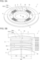
- FIG. 5A is a schematic diagram of the vibration insulator 1 to be mounted between the cartridge 5 and the wheel-side housing 6h according to another embodiment of the present invention, where the vibration insulator 1 includes a wave-shaped plate spring part 45.
- FIG. 3 is a schematic diagram of the vibration insulator 1 to be mounted between the cartridge 5 and the wheel-side housing 6h according to an embodiment of the present invention, where the vibration insulator 1 includes a wave-shaped plate spring part 45.
- FIG. 5B is an enlarged view of the wave-shaped plate spring part 45 of FIG. 5A .
- FIG. 6 is a schematic diagram showing a state where the vibration insulator 1 of FIG. 5A is disposed between the cartridge 5 and the wheel-side housing 6h.
- the wheel means the turbine wheel 53 or the compressor wheel 54 described above
- the wheel-side housing 6h means the turbine-side housing member 6t or the compressor-side housing member 6c in accordance with the type of the wheel.
- the vibration insulator 1 is disposed between the cartridge 5 and the turbine-side housing member 6t and between the cartridge 5 and the compressor-side housing member 6c each
- the description is interpreted as meaning that the wheel is the turbine wheel 53 and the compressor wheel 54
- the wheel-side housing 6h means the turbine-side housing member 6t and the compressor-side housing member 6c.
- the axial direction of the rotational shaft 51r of the cartridge 5 is simply referred to as the axial direction as appropriate; and in the axial direction, a side at which the wheel is located is referred to as wheel side Dw, and a side opposite to the wheel side is referred to as cartridge side Dc.
- the vibration insulator 1 is mounted between the cartridge 5 (described above) which includes: the rotor 51 having the wheel (53, 54) and the rotational shaft 51r; and the bearing housing 52 accommodating the bearing 52b rotatably supporting the rotor 51, and the wheel-side housing 6h (6t, 6c) which is to be pressed to the bearing housing 52 accommodating the wheel in the axial direction of the rotational shaft 51r.
- the vibration insulator 1 is configured to insulate vibration to be mutually transmitted between the cartridge 5 and the wheel-side housing 6h (reduce vibration to be transmitted).
- the vibration insulator 1 includes an outer ring portion 2, an inner ring portion 3, and a flexible support portion 4.
- the outer ring portion 2 has an annular (cylindrical) shape, such as a circular ring shape, and has a wheel-side contact surface 2fw configured to come into contact with the wheel-side housing 6h (see FIGs. 4 and 6 ). That is, the annular vibration insulator 1 is supported to the wheel-side housing 6h by the outer ring portion 2 in contact with the wheel-side housing 6h at the wheel-side contact surface 2fw. More specifically, as shown in FIGs. 4 and 6 , the outer ring portion 2 may be fixed to the wheel-side housing 6h with a bolt 67. In the embodiments shown in FIGs.
- the outer ring portion 2 includes a flange part 15 extending around the entire outer circumference of the outer ring portion 2 and having a bolt hole allowing the bolt 67 to be inserted therein (see FIGs. 3 and 5A ), and is fixed to the wheel-side housing 6h with the bolt 67, while being in contact with a sealing member 64 (described later) of the wheel-side housing 6h.
- the inner ring portion 3 has an annular (cylindrical) shape, such as a circular ring shape, and is disposed inside the outer ring portion 2 with a clearance S from the outer ring portion 2.
- This clearance S is formed between the entire outer circumference of the inner ring portion 3 and the entire inner circumference of the outer ring portion. That is, the inner ring portion 3 is not directly connected to the outer ring portion 2, and the flexible support portion 4 described later is interposed between and connects the inner ring portion 3 and the outer ring portion 2 (see FIGs. 3 , 5A, and 5B ).
- the inner ring portion 3 has a bearing-side contact surface 3fb configured to come into contact with the bearing housing 52. In the embodiments shown in FIGs.
- an axial end portion of the bearing housing 52 includes an insertion part 52i inserted into a space (central space 3s) in the center of the annular inner ring portion 3 and a flange part 52f having a larger diameter than the insertion part 52i.
- the cartridge 5 is pressed toward the wheel-side housing 6h (wheel side Dw) facing in the axial direction; conversely, the wheel-side housing 6h is pressed toward the cartridge 5 (cartridge side Dc) facing in the axial direction (hereinafter, this state is referred to as support state, as appropriate).
- this state is referred to as support state, as appropriate.
- the flexible support portion 4 deforms in the axial direction in accordance with the magnitude of the pressing forces (clamping forces); conversely, when the pressing forces are removed, it returns to the initial state where no pressing force is applied (elastic deformation).
- the flexible support portion 4 is elastically deformable also in the radial direction of the rotational shaft 51r (hereinafter, simply referred to as radial direction) as described later, and thus the flexible support portion 4 elastically deforms in the radial direction or the axial direction in response to vibration.
- the flexible support portion 4 reduces (damps) vibration transmitted from the unbalance detection device 6 side to the outer ring portion 2 via the wheel-side housing 6h. Further, it damps (reduces) vibration upon rotation mainly caused by unbalance of the rotor 51, transmitted to the inner ring portion 3 via the bearing housing 52.
- each of the outer ring portion 2, the inner ring portion 3, and the flexible support portion 4 is made of metal.
- the vibration insulator 1 may be produced by casting or grinding a single sheet of a metal material (e.g., wire cutting).
- the vibration insulator 1 is preferably made of metal to withstand a large pressing force applied in the axial direction in the support state.
- the metallic insulator is also excellent in durability compared with one made of a resin or rubber.
- the present invention is not limited to these embodiments.
- at least one of the outer ring portion 2, the inner ring portion 3, and the flexible support portion 4 may be produced from a material which is not metal but a heat-resistant resin or rubber.
- the cartridge 5 is supported by the support mechanism via the vibration insulator 1 in a state where the cartridge 5 is not directly in contact with the wheel-side housing 6h, but with the vibration insulator 1. In other words, the cartridge 5 is supported by the support mechanism only via the vibration insulator 1. Further, in the support state of the cartridge 5, as described above, if vibration occurs due to unbalance of the rotor 51 upon rotation of the rotor 51 inside the cartridge 5 for the unbalance detection work, the vibration is transmitted from the bearing housing 52 supporting the bearing 52b to the inner ring portion 3 in contact with the bearing housing 52.
- the vibration transmitted to the inner ring portion 3 attempts to be transmitted to the outer ring portion 2 and the wheel-side housing 6h sequentially, via the flexible support portion 4.
- vibration occurring on the unbalance detection device 6 side is transmitted from the wheel-side housing 6h to the outer ring portion 2 and then attempts to be transmitted to the inner ring portion 3 and the cartridge 5 (bearing housing 52) via the flexible support portion 4.
- the flexible support portion 4 elastically deforms in the radial direction or the axial direction in response to the transmitted vibration, thereby sufficiently damping (reducing) the vibration from the outer ring portion 2 toward the inner ring portion 3 or from the inner ring portion 3 toward the outer ring portion 2.
- the vibration insulator 1 with the above configuration provides a sufficient damping effect even without using a material having low elastic modulus such as rubber. Accordingly, by producing the vibration insulator 1 from a material having high strength such as metal, it is possible to provide the vibration insulator 1 excellent in durability.
- FIGs. 3 and 4 show an embodiment relating to the annular plate spring part 41
- FIGs. 5A to 6 show an embodiment relating to the wave-shaped plate spring part 45.
- the flexible support portion 4 of the vibration insulator 1 includes an annular plate spring part 41 of annular shape disposed in the clearance S formed between the outer ring portion 2 and the inner ring portion 3, an outer-ring-side joint part 42 connecting a part of the annular plate spring part 41 and the outer ring portion 2, and an inner-ring-side joint part 43 connecting a part of the annular plate spring part 41 and the inner ring portion 3 at a portion different in the circumferential direction from a portion where the outer-ring-side joint part 42 is connected to the annular plate spring part 41.
- the outer ring portion 2 is supported to the wheel-side housing 6h, and the annular plate spring part 41 is supported to the outer ring portion 2 via the outer-ring-side joint part 42 and supports the inner ring portion 3 via the inner-ring-side joint part 43.
- the annular plate spring part 41 is provided in the clearance S between the outer ring portion 2 and the inner ring portion 3, in a state where the annular plate spring part 41 has an outer clearance S1 from the outer ring portion 2 and an inner clearance S2 from the inner ring portion 3 except for jointed portions with the outer-ring-side joint part 42 and the inner-ring-side joint part 43.
- the outer clearance S1 and the inner clearance S2 are formed between the outer ring portion 2 and the inner ring portion 3 defined on the annular member to reduce stiffness at this portion and enable elastic deformation at a portion (annular plate spring part 41) between the outer clearance S1 and the inner clearance S2.
- the annular plate spring part 41 is elastically displaced in the radial direction or the axial direction in response to vibration from the outer ring portion 2 toward the inner ring portion 3 or vibration from the inner ring portion 3 toward the outer ring portion 2 to damp (reduce) vibration, thus enabling vibration insulation.
- the outer clearance S1 and the inner clearance S2 exist, collision of the annular plate spring part 41 with the outer ring portion 2 or the inner ring portion 3 at elastic deformation is avoided.
- the elastic deformable flexible support portion 4 can be formed by the annular plate spring part 41 mutually connecting the outer ring portion 2 and the inner ring portion 3.
- the outer-ring-side joint part 42 and the inner-ring-side joint part 43 may be located on the same line, namely, a first straight line La passing through the center O of the inner ring portion 3.
- the outer ring portion 2, the inner ring portion 3, and the flexible support portion 4 formed in an annular (cylindrical) shape are concentric about the center O.
- outer-ring-side joint part 42 and the inner-ring-side joint part 43 are arranged so that the first straight line La passes through the center of the outer-ring-side joint part 42 and the center of the inner-ring-side joint part 43 in the circumferential direction of the rotational shaft 51r (hereinafter, simply referred to as circumferential direction).
- circumferential direction the outer-ring-side joint part 42 and the inner-ring-side joint part 43 are disposed 180 degrees opposite to each other across the center O.
- the annular plate spring part 41 can flexibly elastically deform in the axial direction or the radial direction at each position on the entire circumference of the annular plate spring part 41 in response to vibration transmitted to the annular plate spring part 41, compared with a case where the outer-ring-side joint part 42 and the inner-ring-side joint part 43 are not located on the first straight line La. Thus, it is possible to more effectively insulate vibration.
- the vibration insulator 1 which enables appropriate vibration insulation with respect to vibration transmitted to the annular plate spring part 41 while ensuring an appropriate durability to the pressing force for pressing the bearing housing 52 to the wheel-side housing 6h.
- the present invention is not limited to the present embodiment.
- the outer-ring-side joint part 42 and the inner-ring-side joint part 43 may not be located on the same first straight line La.
- an angle ⁇ between a first-end-side straight line Lb passing through the center O of the inner ring portion 3 and a first end of the inner-ring-side joint part 43 in the circumferential direction and a second-end-side straight line Lc passing through the center O of the inner ring portion 3 and a second end of the inner-ring-side joint part 43 in the circumferential direction may be 30 degrees or more and 90 degrees or less (30° ⁇ 90°).
- the inner-ring-side joint part 43 is disposed on a part of the inner circumference of the annular plate spring part 41 and the outer circumstance of the inner ring portion 3, and the inner-ring-side joint part 43 is formed so as to have a length in the circumferential direction within a range of 30 degrees or more and 90 degrees or less around the center O.
- the outer-ring-side joint part 42 has the same length in the circumferential direction as the inner-ring-side joint part 43.
- the present invention is not limited to the present embodiment. In other embodiments, the outer-ring-side joint part 42 and the inner-ring-side joint part 43 may have different lengths in the circumferential direction.
- the present invention is not limited to the present embodiment.
- the angle ⁇ between the first-end-side straight line Lb and the second-end-side straight line Lc may be smaller than 30 degrees or may be larger than 90 degrees.
- the flexible support portion 4 includes a plurality of wave-shaped plate spring parts 45 including an elementary wave-shaped plate spring part 46 folded in a wave shape along the radial direction and disposed in the clearance S formed between the outer ring portion 2 and the inner ring portion 3.
- the outer ring portion 2 is supported to the wheel-side housing 6h, and one radial end of each of the wave-shaped plate spring parts 45 is connected to the outer ring portion 2 and thereby is supported to the outer ring portion 2; and the other radial end is connected to the inner ring portion 3 and thereby supports the inner ring portion 3.
- an interwave clearance S4 is formed on an inner side of the fold (side with smaller angle) in the folded wave-shaped structure of the wave-shaped plate spring part 45 (elementary wave-shaped plate spring part 46).
- the stiffness of the wave-shaped plate spring part 45 connecting the outer ring portion 2 and the inner ring portion 3 is decreased, whereby the wave-shaped plate spring part 45 is configured to be elastically deformable.
- each of the wave-shaped plate spring parts 45 is elastically displaced in the radial direction or the axial direction in response to vibration from the outer ring portion 2 toward the inner ring portion 3 or vibration from the inner ring portion 3 toward the outer ring portion 2 to damp (reduce) vibration by using the interwave clearance S4, thus enabling insulation of vibration.
- the elastic deformable flexible support portion 4 can be formed by the plurality of wave-shaped plate spring parts 45 including the elementary wave-shaped plate spring part 46 of wave shape connecting the outer ring portion 2 and the inner ring portion 3.
- this structure is complicated compared with the above-described embodiment in which the flexible support portion 4 has the annular plate spring part 41, it is possible to provide the vibration insulator 1 with more improved vibration insulation property and durability to the pressing force (clamping force) in the axial direction.
- the wave-shaped plate spring parts 45 may be arranged at equal intervals along the circumferential direction in the clearance S formed between the outer ring portion 2 and the inner ring portion 3. In other words, one of the wave-shaped plate spring parts 35 and other two of the wave-shaped plate spring parts 35 on both sides are arranged at a predetermined distance. In the embodiments shown in FIGs. 5A to 5B , the number of the wave-shaped plate spring parts 45 is four, and the four wave-shaped plate spring parts 45 are arranged at equal intervals (i.e., at 90 degrees) in a state separated from each other around the outer ring portion 2 and the inner ring portion 3.
- the provision of the four wave-shaped plate spring parts 45 at intervals of 90 degrees ensures durability to the vibration transmitted toward the wave-shaped plate spring parts 45 from the entire circumstance of the annular outer ring portion 2 or the entire circumstance of the inner ring portion 3.
- the present invention is not limited to the present embodiment, and the number of the wave-shaped plate spring parts 45 may be any number that is two or more, for instance, three or five or more.
- the number of the wave-shaped plate spring parts 45 may be determined in accordance with the magnitude of vibration or the pressing force in the axial direction of the vibration insulator 1.
- each of the wave-shaped plate spring parts 45 can flexibly elastically deform in the axial direction or the radial direction in response to vibration transmitted to the wave-shaped plate spring parts 45, compared with a case where the wave-shaped plate spring parts 45 are not arranged at equal intervals. Thus, it is possible to more effectively insulate vibration.
- the wave-shaped plate spring parts 45 are arranged at equal intervals, it is possible to uniformly distribute the pressing force applied in the axial direction over the wave-shaped plate spring parts 45. Thus, it is possible to prevent the pressing force being concentrated on a part of the wave-shaped plate spring parts 45, and it is possible to provide the vibration insulator 1 which enables appropriate vibration insulation with respect to vibration transmitted to each of the wave-shaped plate spring parts 45 while ensuring an appropriate durability of the vibration insulator 1.
- the present inventors found that, in a limited space (clearance S) formed between the outer ring portion 2 and the inner ring portion 3, for instance, the more the wave-shaped spring structures (elementary wave-shaped plate spring part 46) arranged at equal intervals and the more the wave-shaped folds in the wave-shaped spring structures, the greater the durability to the pressing force and the vibration insulation property in the support state, through mathematical analysis.
- the clearance S between the outer ring portion 2 and the inner ring portion 3 decreases, which can reduce the flexibility of the flexible support portion 4.
- each of the wave-shaped plate spring parts 45 may have a plurality of elementary wave-shaped plate spring parts 46 which are adjacent to each other. That is, in this embodiment, instead of increasing the number of the wave-shaped plate spring parts 45, each of the wave-shaped plate spring parts 45 includes a plurality of elementary wave-shaped plate spring parts 46 so as to increase the wave-shaped spring structures. In this case, as shown in FIG. 5A , a distance along the circumferential direction between the adjacent elementary wave-shaped plate spring parts 46 disposed in each of the wave-shaped plate spring parts 45 is smaller than a distance along the circumferential direction between adjacent two of the wave-shaped plate spring parts 45.
- the number of the elementary wave-shaped plate spring parts 46 may be determined in accordance with the magnitude of vibration or the pressing force in the axial direction of the vibration insulator 1.
- the number of the wave-shaped plate spring parts 45 may be four, and the number of the elementary wave-shaped plate spring parts 46 may be two. That is, in the embodiment shown in FIGs. 5A and 5B , each of the wave-shaped plate spring parts 45 includes two adjacent elementary wave-shaped plate spring parts 46.
- the flexible support portion 4 has eight wave-shaped spring structures in total, and the number of the wave-shaped spring structures (elementary wave-shaped plate spring parts 46) is twice as much as a case where each of the wave-shaped plate spring parts 45 has a single elementary wave-shaped plate spring part 46.
- the present invention is not limited to the present embodiment.
- each of the wave-shaped plate spring parts 45 may have two or more elementary wave-shaped plate spring parts 46. That is, let “n” be the number of the wave-shaped plate spring parts 45, and “m” be the number of the elementary wave-shaped plate spring parts 46, m ⁇ n number of wave-shaped spring structures may be provided.
- each of the wave-shaped plate spring parts 45 includes a plurality of elementary wave-shaped plate spring parts 46, more wave-shaped spring structures can be formed in the limited clearance S formed between the outer ring portion 2 and the inner ring portion 3. Thus, it is possible to improve the insulation performance and appropriate durability to the pressing force of the vibration insulator 1.
- the number of the elementary wave-shaped plate spring parts 46 may be two, and the two elementary wave-shaped plate spring parts 46 (46a, 46b) may be arranged in a line symmetric manner in the radial direction. More specifically, as shown in FIG. 5B , a first elementary wave-shaped plate spring part 46a and a second elementary wave-shaped plate spring part 46b are line-symmetric with respect to a symmetric axis Ld running between the first elementary wave-shaped plate spring part 46a and the second elementary wave-shaped plate spring part 46b along the radial direction.
- W1 represents the length in the circumferential direction of the interwave clearance S4 formed on the inner side of the fold
- W2 represents the maximum interwave clearance S4 formed by the two line-symmetric elementary wave-shaped plate spring parts 46
- W3 represents a clearance between the two elementary wave-shaped plate spring parts 46.
- the two elementary wave-shaped plate spring parts 46 (first elementary wave-shaped plate spring part 46a and second elementary wave-shaped plate spring part 46b) extending in the radial direction are arranged in a line-symmetric manner in the radial direction, it is possible to provide the vibration insulator 1 which enables appropriate vibration insulation.
- the elementary wave-shaped plate spring parts 46 includes a plurality of circumferential plate parts 47, a plurality of first-end-side coupling plate parts 48, and a plurality of second-end-side coupling plate parts 49.
- the circumferential plate parts 47 is a portion of the elementary wave-shaped plate spring part 46 extending in the circumferential direction.
- the elementary wave-shaped plate spring part 46 includes a plurality of circumferential plate parts 47, and the circumferential plate parts 47 are separated from each other in the radial direction.
- first-end-side coupling plate part 48 and the second-end-side coupling plate part 49 are portions of the elementary wave-shaped plate spring part 46 connecting the circumferential plate parts 47, which are separated from each other in the radial direction. Every two of the circumferential plate parts 47 are connected via the first-end-side coupling plate part 48 or the second-end-side coupling plate part 49 so as to form the wave-shaped structure as a whole.
- the third circumferential plate part 47c from the outer ring portion 2 is the middle of a series of three circumferential plate parts 47 (47b, 47c, 47d)
- the third circumferential plate part 47c is adjacent to the second circumferential plate part 47b on the outer ring portion 2 side in the radial direction and is adjacent to the fourth circumferential plate part 47d on the inner ring portion 3 side in the radial direction.
- a first end (on the left side in the figure) of the third circumferential plate part 47c and a first end (on the same side) of the second circumferential plate part 47b are connected to each other via the first first-end-side coupling plate part 48a which extends in the radial direction.
- a second end (on the right side in the figure) of the third circumferential plate part 47c and a second end (on the same side) of the fourth circumferential plate part 47d are connected to each other via the second second-end-side coupling plate part 49b which extends in the radial direction.
- the second end (on the right side in the figure) of the fourth circumferential plate part 47d is connected to the second side of the third circumferential plate part 47c via the second second-end-side coupling plate part 49b, and a first end (on the left side in the figure) thereof is connected to a first end on the same side (left in the figure) of the fifth circumferential plate part 47e via the second first-end-side coupling plate part 48b. Repeating this pattern forms the wave-shaped spring structure.
- the number of the circumferential plate parts 47 may be an odd number of three or more.
- the two line-symmetric elementary wave-shaped plate spring parts 46 are connected to the outer ring portion 2 via a single joint part 4a and is connected to the inner ring portion 3 via two joint parts 4b each contiguous to one of the elementary wave-shaped plate spring parts 46.
- the vibration insulator 1 having appropriate durability to the pressing force and vibration insulation property. Further, when the number of the circumferential plate parts 47 is odd, the numbers of the first-end-side coupling plate part 48 and the second-end-side coupling plate part 49 are the same. Thus, it is possible to equalize the elasticity on the first end side and the elasticity on the second end side in the circumferential plate part 47.
- the wave-shaped folds may be formed in a zigzag shape by directly connecting end portions of the plurality of circumferential plate parts 47.
- the first-end-side coupling plate part 48 and the second-end-side coupling plate part 49 are formed by plate thickness of the plurality of circumferential plate parts 47.
- the wheel-side contact surface 2fw of the outer ring portion 2 is configured to come into contact with a sealing member 64 for preventing air inside the wheel-side housing 6h from leaking via the clearance S formed between the outer ring portion 2 and the inner ring portion 3.
- the sealing member 64 forms a part of the wheel-side housing 6h, and in the embodiments shown in FIGs. 3 to 6 , is attached to the body of the wheel-side housing 6h with the bolt 67.
- the sealing member 64 is fixed with the bolt 67 penetrating these members in the axial direction. Further, with this configuration, the sealing member 64 (described later) is fixed to the wheel-side housing 6h together with the flange part 15 of the outer ring portion 2.
- the vibration insulator 1 has the clearance S, formed between the outer ring portion 2 and the inner ring portion 3, the outer clearance S1, the inner clearance S2, and the interwave clearance S4. Via these clearances, both sides (wheel side Dw and cartridge side Dc) of the vibration insulator 1 communicate with each other. Accordingly, when the cartridge 5 is supported to the wheel-side housing 6h via the vibration insulator 1, the wheel side Dw and the cartridge side Dc of the vibration insulator 1 communicate with each other via the clearance S of the vibration insulator 1.
- the sealing member 64 is disposed on the wheel side Dw of the outer ring portion 2, inner ring portion 3, and the flexible support portion 4.
- the sealing member 64 has an annular shape. In the embodiments shown in FIGs. 4 and 6 , the sealing member 64 has an annular shape in conformance with the vibration insulator 1 and is disposed on the wheel-side housing 6h side as described above. Further, a first seal rubber 66a is disposed on an inner circumferential surface of the annular sealing member 64 on the cartridge side Dc in the axial direction. The sealing member 64 is connected to the inner ring portion 3 via the first seal rubber 66a. This prevents the air inside the wheel-side housing 6h from flowing to the outside from between the sealing member 64 and the inner ring portion 3. Meanwhile, a second seal rubber 66b is disposed on an outer circumferential surface of the sealing member 64 on the wheel side Dw in the axial direction. The sealing member 64 is connected to the wheel-side housing 6h via the second seal rubber 66b. This prevents the air inside the wheel-side housing 6h from flowing to the outside from between the sealing member 64 and the wheel-side housing 6h.
- annular (circular ring-shaped) back plate 65 is disposed in a central space of the annular sealing member 64 and is in contact with the sealing member 64 and the first seal rubber 66a on the inner circumferential side of the sealing member 64.
- the sealing member 64 prevents the air inside the wheel-side housing 6h from flowing to the outside via the clearance S.
- the rotation air supplied into the wheel-side housing 6h to rotate the rotor 51 inside the wheel-side housing 6h is prevented from flowing to the outside via the clearance S. Consequently, the unbalance detection work can be appropriately performed.
- a gap G may be formed between the inner ring portion 3 and the sealing member 64 and between the flexible support portion 4 and the sealing member 64 each.
- the sealing member 64 in the support state, the sealing member 64 separates from the inner ring portion 3 at a distance h1, and the sealing member 64 separates from the flexible support portion 4 at a distance h2.
- the sealing member 64 and the inner ring portion 3, as well as the sealing member 64 and the flexible support portion 4 are not in direct contact.
- the gap G prevents contact between the flexible support portion 4 or the inner ring portion and the sealing member 64 when the flexible support portion 4 or the inner ring portion 3 is significantly displaced relative to the outer ring portion 2 due to vibration.
- the gaps G formed between the sealing member 64 and the inner ring portion 3 and between the sealing member 64 and the flexible support portion 4 prevent direct contact between the sealing member 64 and the inner ring portion 3 or the flexible support portion 4 subjected to elastic deformation due to vibration or the like, thus enabling appropriate vibration insulation. Further, with this configuration, it is possible to prevent breakage of the vibration insulator 1 or the sealing member 64 and ensure the durability of the vibration insulator 1.
- the wheel-side contact surface 2fw of the outer ring portion 2 is configured to be located on the wheel side Dw in the radial direction relative to the inner ring portion 3 and the flexible support portion 4, in a state where the wheel-side housing 6h is not pressed to the bearing housing 52 in the axial direction yet (i.e., initial state). That is, in the initial state, the wheel-side contact surface 2fw of the outer ring portion 2 protrudes from an end surface on the same side (wheel-side end surface 3fw) of the inner ring portion 3 toward the wheel side Dw.
- a distance between the wheel-side contact surface 2fw of the outer ring portion 2 and the wheel-side end surface 3fw of the inner ring portion 3 is equal to or more than the distance h2.
- the vibration insulator 1 can prevent a situation where an end portion (wheel-side end surface 3wf) of the inner ring portion 3 opposite to the bearing-side contact surface 3fb physically interferes with the wheel-side housing 6h side such as the sealing member 64, when the wheel-side housing 6h is pressed to the bearing housing 52 in the axial direction, and thereby the inner ring portion 3 in contact with the bearing housing 52 side is pressed to the wheel-side housing 6h. That is, the gap G can be formed in the support state.
- the bearing-side contact surface 3fb of the inner ring portion 3 may be located on the cartridge side Dc in the radial direction relative to the outer ring portion 2 and the flexible support portion 4, in a state where the wheel-side housing 6h is not pressed to the bearing housing 52 in the axial direction yet (i.e., initial state). More specifically, as shown in FIGs. 4 and 6 , in the initial state, the bearing-side contact surface 3fb of the inner ring portion 3 protrudes from an end surface on the same side (bearing-side end surface 2fb) of the outer ring portion 2 toward the cartridge side Dc.
- a distance between the bearing-side contact surface 3fb of the inner ring portion 3 and the bearing-side end surface 2fb of the outer ring portion 2 is a distance h3.
- the length L1 of the inner ring portion 3 in the axial direction is shorter than a length obtained by adding the length L2 of the outer ring portion 2 in the axial direction and the distance h3 in the axial direction (Li+h3 ⁇ L2).
- the vibration insulator 1 can prevent a situation where an end portion of the inner ring portion 3 opposite to the bearing-side contact surface 3fb physically interferes with the wheel-side housing 6h, when the wheel-side housing 6h is pressed to the bearing housing 52 in the axial direction, and thereby the inner ring portion 3 in contact with the bearing housing 52 side is pressed to the wheel-side housing 6h.
Landscapes
- Engineering & Computer Science (AREA)
- General Engineering & Computer Science (AREA)
- Mechanical Engineering (AREA)
- Physics & Mathematics (AREA)
- Manufacturing & Machinery (AREA)
- General Physics & Mathematics (AREA)
- Acoustics & Sound (AREA)
- Aviation & Aerospace Engineering (AREA)
- Testing Of Balance (AREA)
- Structures Of Non-Positive Displacement Pumps (AREA)
Claims (11)
- Anordnung, umfassend:eine Kartusche (5), umfassend: einen Rotor (51) mit einem Rad (53, 54) und einer Drehwelle (51f); und ein Lagergehäuse (52), das ein Lager (52b) aufnimmt, das den Rotor (51) drehbar lagert;ein radseitiges Gehäuse (6h), das in einer axialen Richtung an das Lagergehäuse (52) zu drücken ist;einen Schwingungsisolator (1), der zwischen der Kartusche (5) und dem radseitigen Gehäuse (6h) angebracht ist,wobei der Schwingungsisolator (1) umfasst:einen ringförmigen Außenringabschnitt (2) mit einer radseitigen Kontaktfläche (2fw), die konfiguriert ist, um mit dem radseitigen Gehäuse (6h) in Kontakt zu kommen;einen ringförmigen Innenringabschnitt (3), der innerhalb des Außenringabschnitts (2) mit einem Zwischenraum vom Außenringabschnitt (2) angeordnet ist und eine lagerseitige Kontaktfläche (3fb) aufweist, die konfiguriert ist, um mit dem Lagergehäuse (52) in Kontakt zu kommen; undeinen flexiblen Stützabschnitt (4), der zwischen dem Außenringabschnitt (2) und dem Innenringabschnitt (3) angeordnet ist und den Außenringabschnitt und den Innenringabschnitt verbindet, wobei der flexible Stützabschnitt (4) elastisch verformbar ist,wobei der flexible Stützabschnitt (4) eine Mehrzahl von wellenförmigen Tellerfederteilen (45) umfasst, die in dem Zwischenraum angeordnet sind und einen elementaren wellenförmigen Tellerfederteil (46) umfassen, der in einer Wellenform entlang einer radialen Richtung gefaltet ist.
- Anordnung nach Patentanspruch 1,
wobei die wellenförmigen Tellerfederteile (45) in gleichen Abständen entlang einer Umfangsrichtung im Zwischenraum angeordnet sind. - Anordnung nach Patentanspruch 1 oder 2,
wobei jeder der wellenförmigen Tellerfederteile (45) eine Mehrzahl von elementaren wellenförmigen Tellerfederteilen (46) aufweist. - Anordnung nach Patentanspruch 3,
wobei jeder elementare wellenförmige Tellerfederteil (46) umfasst:eine Mehrzahl von Umfangsplattenteilen (47), die in der radialen Richtung voneinander getrennt sind und sich jeweils in einer Umfangsrichtung erstrecken;eine Mehrzahl von erstendseitigen Kopplungsplattenteilen (48), die jeweils erste Enden von benachbarten zwei der Umfangsplattenteile (47) auf einer ersten Seite in der radialen Richtung entlang der radialen Richtung verbinden; undeine Mehrzahl von zweitendseitigen Kopplungsplattenteilen (48b), die jeweils zweite Enden von benachbarten zwei der Umfangsplattenteile (47) auf einer zweiten Seite in der radialen Richtung entlang der radialen Richtung verbinden. - Anordnung nach Patentanspruch 4,
wobei die Anzahl der Umfangsplattenteile (47) eine ungerade Zahl von 3 oder mehr ist. - Anordnung nach einem der Patentansprüche 1 bis 5,
wobei die radseitige Kontaktfläche (2fw) des Außenringabschnitts (2) konfiguriert ist, um mit einem Dichtungselement (64) in Kontakt zu kommen, um zu verhindern, dass Luft innerhalb des radseitigen Gehäuses (6h) über den Zwischenraum ausströmt. - Anordnung nach Patentanspruch 6,
wobei ein Spalt zwischen dem Innenringabschnitt (3) und dem Dichtungselement (64) und zwischen dem flexiblen Stützabschnitt (4) und dem Dichtungselement (64) in einem Zustand gebildet ist, in dem die radseitige Schlauchleitung (6h) in der axialen Richtung an das Lagergehäuse (52) gedrückt ist. - Anordnung nach einem der Patentansprüche 1 bis 7,
wobei die radseitige Kontaktfläche (2fw) des Außenringabschnitts (2) auf einer Radseite in einer radialen Richtung relativ zu dem Innenringabschnitt (3) und dem flexiblen Stützabschnitt (4) in einem Zustand angeordnet ist, in dem das radseitige Gehäuse (6h) in der axialen Richtung nicht an das Lagergehäuse (52) gedrückt ist. - Anordnung nach Patentanspruch 8,
wobei die lagerseitige Kontaktfläche (2fb) des Innenringabschnitts (3) auf einer Kartuschenseite in der radialen Richtung relativ zu dem Außenringabschnitt (2) und dem flexiblen Stützabschnitt (4) in einem Zustand angeordnet ist, in dem das radseitige Gehäuse (6h) in der axialen Richtung nicht an das Lagergehäuse (52) gedrückt ist. - Anordnung nach einem der Patentansprüche 1 bis 9,
wobei jeder des Außenringabschnitts (2), des Innenringabschnitts (3) und des flexiblen Stützabschnitts (4) aus einem Metall hergestellt ist. - Unwuchterfassungsvorrichtung zum Erfassen einer Unwucht eines Rotors (51) einer Kartusche (5); wobei die Unwuchterfassungsvorrichtung umfasst:eine Anordnung nach einem der Patentansprüche 1 bis 10;einen Stützmechanismus, der das radseitige Gehäuse an das Lagergehäuse (52) drückt, um die Kartusche (5) zu stützen; undeinen Schwingungssensor (9), der in der Lage ist, eine Schwingung bei Drehung des Rotors (51) zu erfassen.
Applications Claiming Priority (3)
| Application Number | Priority Date | Filing Date | Title |
|---|---|---|---|
| JP2016237649A JP6831225B2 (ja) | 2016-12-07 | 2016-12-07 | 振動絶縁部材、および振動絶縁部材を備えるアンバランス検出装置 |
| PCT/JP2017/043187 WO2018105499A1 (ja) | 2016-12-07 | 2017-11-30 | 振動絶縁部材、および振動絶縁部材を備えるアンバランス検出装置 |
| EP17877700.9A EP3470810B1 (de) | 2016-12-07 | 2017-11-30 | Schwingungsisolierungselement und ungleichgewichtsdetektor mit einem schwingungsisolierungselement |
Related Parent Applications (2)
| Application Number | Title | Priority Date | Filing Date |
|---|---|---|---|
| EP17877700.9A Division-Into EP3470810B1 (de) | 2016-12-07 | 2017-11-30 | Schwingungsisolierungselement und ungleichgewichtsdetektor mit einem schwingungsisolierungselement |
| EP17877700.9A Division EP3470810B1 (de) | 2016-12-07 | 2017-11-30 | Schwingungsisolierungselement und ungleichgewichtsdetektor mit einem schwingungsisolierungselement |
Publications (2)
| Publication Number | Publication Date |
|---|---|
| EP4063689A1 EP4063689A1 (de) | 2022-09-28 |
| EP4063689B1 true EP4063689B1 (de) | 2023-11-01 |
Family
ID=62491009
Family Applications (2)
| Application Number | Title | Priority Date | Filing Date |
|---|---|---|---|
| EP22173797.6A Active EP4063689B1 (de) | 2016-12-07 | 2017-11-30 | Schwingungsisolator und unwuchterfassungsvorrichtung mit schwingungsisolator |
| EP17877700.9A Active EP3470810B1 (de) | 2016-12-07 | 2017-11-30 | Schwingungsisolierungselement und ungleichgewichtsdetektor mit einem schwingungsisolierungselement |
Family Applications After (1)
| Application Number | Title | Priority Date | Filing Date |
|---|---|---|---|
| EP17877700.9A Active EP3470810B1 (de) | 2016-12-07 | 2017-11-30 | Schwingungsisolierungselement und ungleichgewichtsdetektor mit einem schwingungsisolierungselement |
Country Status (5)
| Country | Link |
|---|---|
| US (1) | US11060940B2 (de) |
| EP (2) | EP4063689B1 (de) |
| JP (1) | JP6831225B2 (de) |
| CN (1) | CN109477768A (de) |
| WO (1) | WO2018105499A1 (de) |
Families Citing this family (10)
| Publication number | Priority date | Publication date | Assignee | Title |
|---|---|---|---|---|
| EP3447264B1 (de) * | 2016-05-26 | 2020-07-08 | Mitsubishi Heavy Industries Engine & Turbocharger, Ltd. | Vorrichtung und verfahren zur ungleichgewichtserkennung |
| WO2017203648A1 (ja) * | 2016-05-26 | 2017-11-30 | 三菱重工業株式会社 | アンバランス検出装置、および、アンバランス検出方法 |
| JP6831225B2 (ja) | 2016-12-07 | 2021-02-17 | 三菱重工エンジン&ターボチャージャ株式会社 | 振動絶縁部材、および振動絶縁部材を備えるアンバランス検出装置 |
| JP7045470B2 (ja) * | 2018-09-06 | 2022-03-31 | 三菱重工エンジン&ターボチャージャ株式会社 | 振動絶縁保持装置 |
| CN111668986A (zh) * | 2020-07-13 | 2020-09-15 | 新乡市通用电机有限公司 | 一种防水功能的侧板振动电机 |
| CN113027981B (zh) * | 2021-04-30 | 2022-04-29 | 中国人民解放军国防科技大学 | 缓冲减振装置和缓冲减振系统 |
| CN114486076B (zh) * | 2022-04-14 | 2022-06-17 | 西华大学 | 氢能混合动力商用车发动机曲轴动平衡专用测试机构 |
| CN115263962B (zh) * | 2022-07-08 | 2026-02-27 | 天津大学 | 一种用于水下航行器的姿态调节超材料隔振器 |
| CN117288383B (zh) * | 2023-11-23 | 2024-05-10 | 南通进宝机械制造有限公司 | 一种基于数据分析的机器静动平衡优化测试方法 |
| CN121222862B (zh) * | 2025-11-28 | 2026-01-30 | 江苏友发钢管有限公司 | 一种钢管冷弯成型装置 |
Family Cites Families (65)
| Publication number | Priority date | Publication date | Assignee | Title |
|---|---|---|---|---|
| US1209730A (en) * | 1912-07-23 | 1916-12-26 | Expl Des Procedes Westinghouse Leblanc Sa | Automatic balancer for rotating bodies. |
| US2874008A (en) * | 1956-02-23 | 1959-02-17 | Skf Svenska Kullagerfab Ab | Bearing mounting for silent running rotating machine parts |
| JPS4854332A (de) * | 1971-11-12 | 1973-07-31 | ||
| IT979709B (it) * | 1972-03-23 | 1974-09-30 | Vulkan Kupplung Getriebe | Giunto cedevole per alberi |
| US4325259A (en) | 1980-10-07 | 1982-04-20 | Westinghouse Electric Corp. | Vibration amplitude measuring device |
| JPS5872302A (ja) | 1981-10-26 | 1983-04-30 | Hitachi Ltd | 第三軌条集電装置 |
| JPS61217737A (ja) | 1985-03-23 | 1986-09-27 | Ngk Insulators Ltd | タ−ボチャ−ジャ−ロ−タの回転試験方法並びにそのための装置 |
| JPH0718746B2 (ja) | 1985-05-21 | 1995-03-06 | 株式会社明電舍 | 回転体の異常検出装置 |
| JPS62135743A (ja) | 1985-12-10 | 1987-06-18 | Mitsubishi Heavy Ind Ltd | バランシング方法 |
| US4864859A (en) | 1988-07-25 | 1989-09-12 | Allied-Signal Inc. | Method for dynamically balancing a mechanism having a high speed rotating component |
| US4900165A (en) * | 1988-08-15 | 1990-02-13 | Union Carbide Corporation | Bearing support system |
| US5102694A (en) * | 1990-09-27 | 1992-04-07 | Cvd Incorporated | Pulsed chemical vapor deposition of gradient index optical material |
| US5197010A (en) | 1990-12-13 | 1993-03-23 | The Boeing Company | Apparatus for continuously actively balancing rotors |
| JPH04103234U (ja) | 1991-01-25 | 1992-09-07 | 日野自動車工業株式会社 | ターボチヤージヤの回転速度検出装置 |
| KR970001606B1 (ko) | 1993-11-12 | 1997-02-11 | 한국기계연구원 | 겹판스프링을 이용한 횡진동 절연장치 |
| US5531642A (en) * | 1993-11-16 | 1996-07-02 | Honda Giken Kogyo Kabushiki Kaisha | Vibration-proof power take-off device for engine including two displacement absorbing joint members connected by a resilient member |
| US6171192B1 (en) * | 1996-02-29 | 2001-01-09 | Exedy Corporation | Flywheel assembly employing a damper mechanism having an annular chamber filled with a dry lubricant |
| US5901616A (en) * | 1997-09-15 | 1999-05-11 | Sikorsky Aircraft Corporation | Inertial mass for vibration isolators |
| US6170989B1 (en) * | 1998-06-10 | 2001-01-09 | Kmc, Inc. | Modular support structure for hydrodynamic bearing |
| JP3835501B2 (ja) | 1998-08-11 | 2006-10-18 | Nok株式会社 | 弾性カップリング |
| JP2001074547A (ja) | 1999-07-05 | 2001-03-23 | Nippon Densan Corp | 特性表示方法、特性表示システムおよび特性表示プログラムを記憶した記録媒体 |
| US6474166B1 (en) | 1999-07-05 | 2002-11-05 | Nidec Corporation | Method for indicating characteristics of rotating apparatus or vibrating apparatus |
| US6318527B1 (en) * | 1999-12-03 | 2001-11-20 | Sikorsky Aircraft Corporation | Inertial vibration isolator spring for helicopter |
| DE19958036A1 (de) * | 1999-12-04 | 2001-06-07 | Optimer Polymer Technik Gmbh | Federelement, vorzugsweise Torsionsdämpfer, insb. für Vorrichtungen zum Heben und Senken von Kraftfahrzeugfensterscheiben |
| JP2001296917A (ja) | 2000-04-11 | 2001-10-26 | Emc Kk | 精密電子機器の挙動と環境監視システム |
| KR100439651B1 (ko) | 2000-11-06 | 2004-07-12 | 미츠비시 쥬고교 가부시키가이샤 | 스크롤 압축기 |
| US8834027B2 (en) * | 2011-01-13 | 2014-09-16 | Fouad Y. Zeidan | Damper having modular flexible ligaments and variable gaps |
| JP2003240054A (ja) | 2002-02-21 | 2003-08-27 | Toyota Motor Corp | ロータのアンバランス修正方法 |
| JP4236510B2 (ja) | 2002-05-16 | 2009-03-11 | 国際計測器株式会社 | 回転体の回転バランス測定装置および測定方法 |
| US7444877B2 (en) | 2002-08-20 | 2008-11-04 | The Regents Of The University Of California | Optical waveguide vibration sensor for use in hearing aid |
| JP2004278580A (ja) | 2003-03-13 | 2004-10-07 | Hiroshi Kamiyoshi | 筒状ダンパ要素 |
| DE102005053786A1 (de) | 2005-11-09 | 2007-05-10 | Schenck Rotec Gmbh | Verfahren und Vorrichtung zum dynamischen Messen der Unwucht eines Rotors |
| KR20070056700A (ko) | 2005-11-30 | 2007-06-04 | 현대자동차주식회사 | 터보 차저의 터보랙 저감장치 |
| US7415878B2 (en) | 2006-08-24 | 2008-08-26 | Honeywell International, Inc. | Ball bearing turbocharger balancer |
| JP4232841B2 (ja) | 2007-07-05 | 2009-03-04 | トヨタ自動車株式会社 | 高速回転機器のアンバランス修正装置 |
| JP4192996B1 (ja) | 2007-07-19 | 2008-12-10 | トヨタ自動車株式会社 | 高速回転機器のアンバランス修正装置 |
| US8083413B2 (en) * | 2007-10-23 | 2011-12-27 | General Electric Company | Compliant hybrid gas journal bearing using integral wire mesh dampers |
| DE102007058592A1 (de) | 2007-12-04 | 2009-06-10 | Schenck Rotec Gmbh | Vorrichtung zum dynamischen Messen der Unwucht des Rotors eines Turboladers |
| DE102009010126A1 (de) * | 2008-03-03 | 2009-09-10 | Luk Lamellen Und Kupplungsbau Beteiligungs Kg | Drehschwingungsdämpfer |
| US8066266B2 (en) * | 2008-03-06 | 2011-11-29 | The Pullman Company | End plated shear-hub isolator |
| DE102008025906A1 (de) | 2008-05-29 | 2009-12-03 | Schenck Rotec Gmbh | Verfahren und Anlage zum Auswuchten des Rotors einer Turbolader-Rumpfgruppe |
| JP5262392B2 (ja) * | 2008-07-23 | 2013-08-14 | 株式会社Ihi | 回転機械支持装置及びその設計方法 |
| WO2011046758A2 (en) | 2009-10-16 | 2011-04-21 | Borgwarner Inc. | Method for determining bearing play of exhaust-gas-turbocharger friction bearings |
| JP2011106845A (ja) | 2009-11-13 | 2011-06-02 | Ihi Corp | アンバランス量測定方法と装置 |
| DE102010036954B4 (de) * | 2010-08-12 | 2016-03-31 | Schenck Rotec Gmbh | Verfahren und Vorrichtung zum dynamischen Messen der Unwucht des Rotors einer Turbolader-Rumpfgruppe |
| EP2678654B1 (de) | 2011-02-24 | 2015-10-28 | AVL List GmbH | Verfahren für die funktionsprüfung von turbomaschinen, sowie prüfeinrichtung dafür |
| PL2581553T3 (pl) * | 2011-10-11 | 2018-09-28 | Schenck Rotec Gmbh | Sposób i urządzenie do dynamicznego pomiaru niewyważenia wirnika rdzenia turbosprężarki |
| US10274364B2 (en) | 2013-01-14 | 2019-04-30 | Virginia Tech Intellectual Properties, Inc. | Analysis of component having engineered internal space for fluid flow |
| WO2014128927A1 (ja) | 2013-02-22 | 2014-08-28 | 三菱重工業株式会社 | コンプレッサホイール、及びコンプレッサアセンブリのアンバランス検出装置 |
| JP2014215160A (ja) | 2013-04-25 | 2014-11-17 | トヨタ自動車株式会社 | 過給機のバランス修正装置およびバランス修正方法 |
| GB2517163A (en) | 2013-08-13 | 2015-02-18 | Universal Balancing Ltd | An apparatus for transporting a rotor |
| US9696216B2 (en) | 2013-09-04 | 2017-07-04 | Siemens Energy, Inc. | Acoustic transducer in system for gas temperature measurement in gas turbine engine |
| WO2015036021A1 (de) | 2013-09-12 | 2015-03-19 | Siemens Aktiengesellschaft | Verfahren und anordnung zur überwachung einer technischen einrichtung wie z.b. einer maschine oder einer anlage |
| JP6266985B2 (ja) | 2014-01-10 | 2018-01-24 | 住友理工株式会社 | 能動型制振装置 |
| US10520386B2 (en) | 2014-06-27 | 2019-12-31 | Mitsubishi Heavy Industries Engine & Turbocharger, Ltd. | Vibration measurement device and method for high-speed rotating machines |
| US20160102554A1 (en) | 2014-10-08 | 2016-04-14 | Caterpillar Inc. | Inspection and qualification for remanufacturing of compressor wheels |
| CN204239602U (zh) | 2014-11-28 | 2015-04-01 | 株洲时代新材料科技股份有限公司 | 用于旋转轴上的圆环形动力吸振器 |
| US9181804B1 (en) | 2015-02-17 | 2015-11-10 | Borgwarner Inc. | Ball bearing turbocharger balancer |
| CN104895807B (zh) | 2015-06-04 | 2018-04-03 | 重庆美的通用制冷设备有限公司 | 离心压缩机 |
| WO2017203648A1 (ja) | 2016-05-26 | 2017-11-30 | 三菱重工業株式会社 | アンバランス検出装置、および、アンバランス検出方法 |
| CN106641057B (zh) * | 2016-11-28 | 2018-10-19 | 杭州电子科技大学 | 一种用于柔顺关节的双层平面扭簧 |
| JP6831225B2 (ja) | 2016-12-07 | 2021-02-17 | 三菱重工エンジン&ターボチャージャ株式会社 | 振動絶縁部材、および振動絶縁部材を備えるアンバランス検出装置 |
| US10495693B2 (en) | 2017-06-01 | 2019-12-03 | General Electric Company | Wind turbine fault detection using acoustic, vibration, and electrical signals |
| US11451108B2 (en) * | 2017-08-16 | 2022-09-20 | Ifit Inc. | Systems and methods for axial impact resistance in electric motors |
| CN108757830B (zh) * | 2018-05-25 | 2019-12-31 | 上海工程技术大学 | 一种用于分布式电动汽车的轮毂电机的减振装置 |
-
2016
- 2016-12-07 JP JP2016237649A patent/JP6831225B2/ja active Active
-
2017
- 2017-11-30 CN CN201780045199.1A patent/CN109477768A/zh active Pending
- 2017-11-30 EP EP22173797.6A patent/EP4063689B1/de active Active
- 2017-11-30 EP EP17877700.9A patent/EP3470810B1/de active Active
- 2017-11-30 US US16/313,319 patent/US11060940B2/en active Active
- 2017-11-30 WO PCT/JP2017/043187 patent/WO2018105499A1/ja not_active Ceased
Also Published As
| Publication number | Publication date |
|---|---|
| US11060940B2 (en) | 2021-07-13 |
| EP3470810B1 (de) | 2022-06-22 |
| EP3470810A1 (de) | 2019-04-17 |
| JP6831225B2 (ja) | 2021-02-17 |
| US20190162622A1 (en) | 2019-05-30 |
| EP4063689A1 (de) | 2022-09-28 |
| WO2018105499A1 (ja) | 2018-06-14 |
| CN109477768A (zh) | 2019-03-15 |
| JP2018091808A (ja) | 2018-06-14 |
| EP3470810A4 (de) | 2019-11-27 |
Similar Documents
| Publication | Publication Date | Title |
|---|---|---|
| EP3470810B1 (de) | Schwingungsisolierungselement und ungleichgewichtsdetektor mit einem schwingungsisolierungselement | |
| US9309922B2 (en) | Set of rolling bearings and corresponding rotary machine | |
| US9033124B2 (en) | Damper device for rotating machine | |
| EP3444463B1 (de) | Unwuchterfassungsvorrichtung und unwuchterfassungsverfahren | |
| CA2496911A1 (en) | Compliant foil-fluid bearing support arrangement | |
| JP2008039183A (ja) | 真空ポンプの軸の支持装置 | |
| US7517155B2 (en) | Resilient mount of uniform stiffness | |
| CN109790868A (zh) | 用于离心式压缩机的驱动轴的轴向轴承装置 | |
| EP2977739A1 (de) | Trägervorrichtung für rotationsmaschine | |
| EP3502642B1 (de) | Vibrationsdetektionsvorrichtung und unwuchtdetektionsvorrichtung mit einer vibrationsdetektionsvorrichtung | |
| KR101513104B1 (ko) | 분할구조를 갖는 에어 포일 베어링 | |
| US10415644B2 (en) | Rotary machine | |
| CN117120732A (zh) | 具有外套筒的模块化径向箔片轴承 | |
| JP5262392B2 (ja) | 回転機械支持装置及びその設計方法 | |
| CN103994733B (zh) | 角度测量装置 | |
| EP2789807B1 (de) | Turbolader | |
| JP7045470B2 (ja) | 振動絶縁保持装置 | |
| CN114441167B (zh) | 码盘支架工装 | |
| CN112087107B (zh) | 位置检测器的连接器 | |
| US20240123813A1 (en) | Rotor alignment compensation with friction material | |
| CN110850903B (zh) | 转轴径向振动主动控制系统及主动控制方法 |
Legal Events
| Date | Code | Title | Description |
|---|---|---|---|
| PUAI | Public reference made under article 153(3) epc to a published international application that has entered the european phase |
Free format text: ORIGINAL CODE: 0009012 |
|
| STAA | Information on the status of an ep patent application or granted ep patent |
Free format text: STATUS: THE APPLICATION HAS BEEN PUBLISHED |
|
| AC | Divisional application: reference to earlier application |
Ref document number: 3470810 Country of ref document: EP Kind code of ref document: P |
|
| AK | Designated contracting states |
Kind code of ref document: A1 Designated state(s): AL AT BE BG CH CY CZ DE DK EE ES FI FR GB GR HR HU IE IS IT LI LT LU LV MC MK MT NL NO PL PT RO RS SE SI SK SM TR |
|
| STAA | Information on the status of an ep patent application or granted ep patent |
Free format text: STATUS: REQUEST FOR EXAMINATION WAS MADE |
|
| 17P | Request for examination filed |
Effective date: 20230309 |
|
| RBV | Designated contracting states (corrected) |
Designated state(s): AL AT BE BG CH CY CZ DE DK EE ES FI FR GB GR HR HU IE IS IT LI LT LU LV MC MK MT NL NO PL PT RO RS SE SI SK SM TR |
|
| GRAP | Despatch of communication of intention to grant a patent |
Free format text: ORIGINAL CODE: EPIDOSNIGR1 |
|
| STAA | Information on the status of an ep patent application or granted ep patent |
Free format text: STATUS: GRANT OF PATENT IS INTENDED |
|
| INTG | Intention to grant announced |
Effective date: 20230612 |
|
| GRAS | Grant fee paid |
Free format text: ORIGINAL CODE: EPIDOSNIGR3 |
|
| GRAA | (expected) grant |
Free format text: ORIGINAL CODE: 0009210 |
|
| STAA | Information on the status of an ep patent application or granted ep patent |
Free format text: STATUS: THE PATENT HAS BEEN GRANTED |
|
| AC | Divisional application: reference to earlier application |
Ref document number: 3470810 Country of ref document: EP Kind code of ref document: P |
|
| AK | Designated contracting states |
Kind code of ref document: B1 Designated state(s): AL AT BE BG CH CY CZ DE DK EE ES FI FR GB GR HR HU IE IS IT LI LT LU LV MC MK MT NL NO PL PT RO RS SE SI SK SM TR |
|
| REG | Reference to a national code |
Ref country code: GB Ref legal event code: FG4D |
|
| REG | Reference to a national code |
Ref country code: CH Ref legal event code: EP |
|
| REG | Reference to a national code |
Ref country code: IE Ref legal event code: FG4D |
|
| REG | Reference to a national code |
Ref country code: DE Ref legal event code: R096 Ref document number: 602017076219 Country of ref document: DE |
|
| REG | Reference to a national code |
Ref country code: LT Ref legal event code: MG9D |
|
| REG | Reference to a national code |
Ref country code: NL Ref legal event code: MP Effective date: 20231101 |
|
| PG25 | Lapsed in a contracting state [announced via postgrant information from national office to epo] |
Ref country code: GR Free format text: LAPSE BECAUSE OF FAILURE TO SUBMIT A TRANSLATION OF THE DESCRIPTION OR TO PAY THE FEE WITHIN THE PRESCRIBED TIME-LIMIT Effective date: 20240202 |
|
| PG25 | Lapsed in a contracting state [announced via postgrant information from national office to epo] |
Ref country code: IS Free format text: LAPSE BECAUSE OF FAILURE TO SUBMIT A TRANSLATION OF THE DESCRIPTION OR TO PAY THE FEE WITHIN THE PRESCRIBED TIME-LIMIT Effective date: 20240301 |
|
| PG25 | Lapsed in a contracting state [announced via postgrant information from national office to epo] |
Ref country code: LT Free format text: LAPSE BECAUSE OF FAILURE TO SUBMIT A TRANSLATION OF THE DESCRIPTION OR TO PAY THE FEE WITHIN THE PRESCRIBED TIME-LIMIT Effective date: 20231101 |
|
| REG | Reference to a national code |
Ref country code: AT Ref legal event code: MK05 Ref document number: 1627535 Country of ref document: AT Kind code of ref document: T Effective date: 20231101 |
|
| PG25 | Lapsed in a contracting state [announced via postgrant information from national office to epo] |
Ref country code: NL Free format text: LAPSE BECAUSE OF FAILURE TO SUBMIT A TRANSLATION OF THE DESCRIPTION OR TO PAY THE FEE WITHIN THE PRESCRIBED TIME-LIMIT Effective date: 20231101 |
|
| PG25 | Lapsed in a contracting state [announced via postgrant information from national office to epo] |
Ref country code: AT Free format text: LAPSE BECAUSE OF FAILURE TO SUBMIT A TRANSLATION OF THE DESCRIPTION OR TO PAY THE FEE WITHIN THE PRESCRIBED TIME-LIMIT Effective date: 20231101 |
|
| PG25 | Lapsed in a contracting state [announced via postgrant information from national office to epo] |
Ref country code: ES Free format text: LAPSE BECAUSE OF FAILURE TO SUBMIT A TRANSLATION OF THE DESCRIPTION OR TO PAY THE FEE WITHIN THE PRESCRIBED TIME-LIMIT Effective date: 20231101 |
|
| PG25 | Lapsed in a contracting state [announced via postgrant information from national office to epo] |
Ref country code: NL Free format text: LAPSE BECAUSE OF FAILURE TO SUBMIT A TRANSLATION OF THE DESCRIPTION OR TO PAY THE FEE WITHIN THE PRESCRIBED TIME-LIMIT Effective date: 20231101 Ref country code: LT Free format text: LAPSE BECAUSE OF FAILURE TO SUBMIT A TRANSLATION OF THE DESCRIPTION OR TO PAY THE FEE WITHIN THE PRESCRIBED TIME-LIMIT Effective date: 20231101 Ref country code: IS Free format text: LAPSE BECAUSE OF FAILURE TO SUBMIT A TRANSLATION OF THE DESCRIPTION OR TO PAY THE FEE WITHIN THE PRESCRIBED TIME-LIMIT Effective date: 20240301 Ref country code: GR Free format text: LAPSE BECAUSE OF FAILURE TO SUBMIT A TRANSLATION OF THE DESCRIPTION OR TO PAY THE FEE WITHIN THE PRESCRIBED TIME-LIMIT Effective date: 20240202 Ref country code: ES Free format text: LAPSE BECAUSE OF FAILURE TO SUBMIT A TRANSLATION OF THE DESCRIPTION OR TO PAY THE FEE WITHIN THE PRESCRIBED TIME-LIMIT Effective date: 20231101 Ref country code: BG Free format text: LAPSE BECAUSE OF FAILURE TO SUBMIT A TRANSLATION OF THE DESCRIPTION OR TO PAY THE FEE WITHIN THE PRESCRIBED TIME-LIMIT Effective date: 20240201 Ref country code: AT Free format text: LAPSE BECAUSE OF FAILURE TO SUBMIT A TRANSLATION OF THE DESCRIPTION OR TO PAY THE FEE WITHIN THE PRESCRIBED TIME-LIMIT Effective date: 20231101 Ref country code: PT Free format text: LAPSE BECAUSE OF FAILURE TO SUBMIT A TRANSLATION OF THE DESCRIPTION OR TO PAY THE FEE WITHIN THE PRESCRIBED TIME-LIMIT Effective date: 20240301 |
|
| PG25 | Lapsed in a contracting state [announced via postgrant information from national office to epo] |
Ref country code: SE Free format text: LAPSE BECAUSE OF FAILURE TO SUBMIT A TRANSLATION OF THE DESCRIPTION OR TO PAY THE FEE WITHIN THE PRESCRIBED TIME-LIMIT Effective date: 20231101 Ref country code: RS Free format text: LAPSE BECAUSE OF FAILURE TO SUBMIT A TRANSLATION OF THE DESCRIPTION OR TO PAY THE FEE WITHIN THE PRESCRIBED TIME-LIMIT Effective date: 20231101 Ref country code: PL Free format text: LAPSE BECAUSE OF FAILURE TO SUBMIT A TRANSLATION OF THE DESCRIPTION OR TO PAY THE FEE WITHIN THE PRESCRIBED TIME-LIMIT Effective date: 20231101 Ref country code: NO Free format text: LAPSE BECAUSE OF FAILURE TO SUBMIT A TRANSLATION OF THE DESCRIPTION OR TO PAY THE FEE WITHIN THE PRESCRIBED TIME-LIMIT Effective date: 20240201 Ref country code: LV Free format text: LAPSE BECAUSE OF FAILURE TO SUBMIT A TRANSLATION OF THE DESCRIPTION OR TO PAY THE FEE WITHIN THE PRESCRIBED TIME-LIMIT Effective date: 20231101 Ref country code: HR Free format text: LAPSE BECAUSE OF FAILURE TO SUBMIT A TRANSLATION OF THE DESCRIPTION OR TO PAY THE FEE WITHIN THE PRESCRIBED TIME-LIMIT Effective date: 20231101 |
|
| REG | Reference to a national code |
Ref country code: CH Ref legal event code: PL |
|
| PG25 | Lapsed in a contracting state [announced via postgrant information from national office to epo] |
Ref country code: DK Free format text: LAPSE BECAUSE OF FAILURE TO SUBMIT A TRANSLATION OF THE DESCRIPTION OR TO PAY THE FEE WITHIN THE PRESCRIBED TIME-LIMIT Effective date: 20231101 |
|
| PG25 | Lapsed in a contracting state [announced via postgrant information from national office to epo] |
Ref country code: LU Free format text: LAPSE BECAUSE OF NON-PAYMENT OF DUE FEES Effective date: 20231130 |
|
| PG25 | Lapsed in a contracting state [announced via postgrant information from national office to epo] |
Ref country code: CH Free format text: LAPSE BECAUSE OF NON-PAYMENT OF DUE FEES Effective date: 20231130 |
|
| PG25 | Lapsed in a contracting state [announced via postgrant information from national office to epo] |
Ref country code: CZ Free format text: LAPSE BECAUSE OF FAILURE TO SUBMIT A TRANSLATION OF THE DESCRIPTION OR TO PAY THE FEE WITHIN THE PRESCRIBED TIME-LIMIT Effective date: 20231101 |
|
| PG25 | Lapsed in a contracting state [announced via postgrant information from national office to epo] |
Ref country code: SK Free format text: LAPSE BECAUSE OF FAILURE TO SUBMIT A TRANSLATION OF THE DESCRIPTION OR TO PAY THE FEE WITHIN THE PRESCRIBED TIME-LIMIT Effective date: 20231101 |
|
| PG25 | Lapsed in a contracting state [announced via postgrant information from national office to epo] |
Ref country code: SM Free format text: LAPSE BECAUSE OF FAILURE TO SUBMIT A TRANSLATION OF THE DESCRIPTION OR TO PAY THE FEE WITHIN THE PRESCRIBED TIME-LIMIT Effective date: 20231101 Ref country code: SK Free format text: LAPSE BECAUSE OF FAILURE TO SUBMIT A TRANSLATION OF THE DESCRIPTION OR TO PAY THE FEE WITHIN THE PRESCRIBED TIME-LIMIT Effective date: 20231101 Ref country code: LU Free format text: LAPSE BECAUSE OF NON-PAYMENT OF DUE FEES Effective date: 20231130 Ref country code: IT Free format text: LAPSE BECAUSE OF FAILURE TO SUBMIT A TRANSLATION OF THE DESCRIPTION OR TO PAY THE FEE WITHIN THE PRESCRIBED TIME-LIMIT Effective date: 20231101 Ref country code: EE Free format text: LAPSE BECAUSE OF FAILURE TO SUBMIT A TRANSLATION OF THE DESCRIPTION OR TO PAY THE FEE WITHIN THE PRESCRIBED TIME-LIMIT Effective date: 20231101 Ref country code: DK Free format text: LAPSE BECAUSE OF FAILURE TO SUBMIT A TRANSLATION OF THE DESCRIPTION OR TO PAY THE FEE WITHIN THE PRESCRIBED TIME-LIMIT Effective date: 20231101 Ref country code: CZ Free format text: LAPSE BECAUSE OF FAILURE TO SUBMIT A TRANSLATION OF THE DESCRIPTION OR TO PAY THE FEE WITHIN THE PRESCRIBED TIME-LIMIT Effective date: 20231101 Ref country code: CH Free format text: LAPSE BECAUSE OF NON-PAYMENT OF DUE FEES Effective date: 20231130 |
|
| REG | Reference to a national code |
Ref country code: BE Ref legal event code: MM Effective date: 20231130 |
|
| REG | Reference to a national code |
Ref country code: DE Ref legal event code: R097 Ref document number: 602017076219 Country of ref document: DE |
|
| PG25 | Lapsed in a contracting state [announced via postgrant information from national office to epo] |
Ref country code: MC Free format text: LAPSE BECAUSE OF FAILURE TO SUBMIT A TRANSLATION OF THE DESCRIPTION OR TO PAY THE FEE WITHIN THE PRESCRIBED TIME-LIMIT Effective date: 20231101 |
|
| PG25 | Lapsed in a contracting state [announced via postgrant information from national office to epo] |
Ref country code: MC Free format text: LAPSE BECAUSE OF FAILURE TO SUBMIT A TRANSLATION OF THE DESCRIPTION OR TO PAY THE FEE WITHIN THE PRESCRIBED TIME-LIMIT Effective date: 20231101 |
|
| PLBE | No opposition filed within time limit |
Free format text: ORIGINAL CODE: 0009261 |
|
| STAA | Information on the status of an ep patent application or granted ep patent |
Free format text: STATUS: NO OPPOSITION FILED WITHIN TIME LIMIT |
|
| REG | Reference to a national code |
Ref country code: IE Ref legal event code: MM4A |
|
| 26N | No opposition filed |
Effective date: 20240802 |
|
| PG25 | Lapsed in a contracting state [announced via postgrant information from national office to epo] |
Ref country code: IE Free format text: LAPSE BECAUSE OF NON-PAYMENT OF DUE FEES Effective date: 20231130 |
|
| PG25 | Lapsed in a contracting state [announced via postgrant information from national office to epo] |
Ref country code: BE Free format text: LAPSE BECAUSE OF NON-PAYMENT OF DUE FEES Effective date: 20231130 |
|
| PG25 | Lapsed in a contracting state [announced via postgrant information from national office to epo] |
Ref country code: FR Free format text: LAPSE BECAUSE OF NON-PAYMENT OF DUE FEES Effective date: 20240101 |
|
| GBPC | Gb: european patent ceased through non-payment of renewal fee |
Effective date: 20240201 |
|
| PG25 | Lapsed in a contracting state [announced via postgrant information from national office to epo] |
Ref country code: SI Free format text: LAPSE BECAUSE OF FAILURE TO SUBMIT A TRANSLATION OF THE DESCRIPTION OR TO PAY THE FEE WITHIN THE PRESCRIBED TIME-LIMIT Effective date: 20231101 |
|
| PG25 | Lapsed in a contracting state [announced via postgrant information from national office to epo] |
Ref country code: SI Free format text: LAPSE BECAUSE OF FAILURE TO SUBMIT A TRANSLATION OF THE DESCRIPTION OR TO PAY THE FEE WITHIN THE PRESCRIBED TIME-LIMIT Effective date: 20231101 Ref country code: IE Free format text: LAPSE BECAUSE OF NON-PAYMENT OF DUE FEES Effective date: 20231130 Ref country code: FR Free format text: LAPSE BECAUSE OF NON-PAYMENT OF DUE FEES Effective date: 20240101 Ref country code: BE Free format text: LAPSE BECAUSE OF NON-PAYMENT OF DUE FEES Effective date: 20231130 |
|
| PG25 | Lapsed in a contracting state [announced via postgrant information from national office to epo] |
Ref country code: GB Free format text: LAPSE BECAUSE OF NON-PAYMENT OF DUE FEES Effective date: 20240201 |
|
| PG25 | Lapsed in a contracting state [announced via postgrant information from national office to epo] |
Ref country code: GB Free format text: LAPSE BECAUSE OF NON-PAYMENT OF DUE FEES Effective date: 20240201 |
|
| PG25 | Lapsed in a contracting state [announced via postgrant information from national office to epo] |
Ref country code: RO Free format text: LAPSE BECAUSE OF FAILURE TO SUBMIT A TRANSLATION OF THE DESCRIPTION OR TO PAY THE FEE WITHIN THE PRESCRIBED TIME-LIMIT Effective date: 20231101 |
|
| PG25 | Lapsed in a contracting state [announced via postgrant information from national office to epo] |
Ref country code: FI Free format text: LAPSE BECAUSE OF FAILURE TO SUBMIT A TRANSLATION OF THE DESCRIPTION OR TO PAY THE FEE WITHIN THE PRESCRIBED TIME-LIMIT Effective date: 20231101 |
|
| PG25 | Lapsed in a contracting state [announced via postgrant information from national office to epo] |
Ref country code: CY Free format text: LAPSE BECAUSE OF FAILURE TO SUBMIT A TRANSLATION OF THE DESCRIPTION OR TO PAY THE FEE WITHIN THE PRESCRIBED TIME-LIMIT; INVALID AB INITIO Effective date: 20171130 |
|
| PG25 | Lapsed in a contracting state [announced via postgrant information from national office to epo] |
Ref country code: HU Free format text: LAPSE BECAUSE OF FAILURE TO SUBMIT A TRANSLATION OF THE DESCRIPTION OR TO PAY THE FEE WITHIN THE PRESCRIBED TIME-LIMIT; INVALID AB INITIO Effective date: 20171130 |
|
| PG25 | Lapsed in a contracting state [announced via postgrant information from national office to epo] |
Ref country code: TR Free format text: LAPSE BECAUSE OF FAILURE TO SUBMIT A TRANSLATION OF THE DESCRIPTION OR TO PAY THE FEE WITHIN THE PRESCRIBED TIME-LIMIT Effective date: 20231101 |
|
| PGFP | Annual fee paid to national office [announced via postgrant information from national office to epo] |
Ref country code: DE Payment date: 20250930 Year of fee payment: 9 |