EP4063703A1 - Strömungsleitung für ein gasförmiges fluid mit einer schallabsorbierenden verkleidung - Google Patents
Strömungsleitung für ein gasförmiges fluid mit einer schallabsorbierenden verkleidung Download PDFInfo
- Publication number
- EP4063703A1 EP4063703A1 EP22164196.2A EP22164196A EP4063703A1 EP 4063703 A1 EP4063703 A1 EP 4063703A1 EP 22164196 A EP22164196 A EP 22164196A EP 4063703 A1 EP4063703 A1 EP 4063703A1
- Authority
- EP
- European Patent Office
- Prior art keywords
- duct
- coating
- conduit
- sound
- absorbent
- Prior art date
- Legal status (The legal status is an assumption and is not a legal conclusion. Google has not performed a legal analysis and makes no representation as to the accuracy of the status listed.)
- Granted
Links
Images


Classifications
-
- F—MECHANICAL ENGINEERING; LIGHTING; HEATING; WEAPONS; BLASTING
- F16—ENGINEERING ELEMENTS AND UNITS; GENERAL MEASURES FOR PRODUCING AND MAINTAINING EFFECTIVE FUNCTIONING OF MACHINES OR INSTALLATIONS; THERMAL INSULATION IN GENERAL
- F16L—PIPES; JOINTS OR FITTINGS FOR PIPES; SUPPORTS FOR PIPES, CABLES OR PROTECTIVE TUBING; MEANS FOR THERMAL INSULATION IN GENERAL
- F16L55/00—Devices or appurtenances for use in, or in connection with, pipes or pipe systems
- F16L55/02—Energy absorbers; Noise absorbers
- F16L55/033—Noise absorbers
- F16L55/0336—Noise absorbers by means of sound-absorbing materials
-
- F—MECHANICAL ENGINEERING; LIGHTING; HEATING; WEAPONS; BLASTING
- F16—ENGINEERING ELEMENTS AND UNITS; GENERAL MEASURES FOR PRODUCING AND MAINTAINING EFFECTIVE FUNCTIONING OF MACHINES OR INSTALLATIONS; THERMAL INSULATION IN GENERAL
- F16L—PIPES; JOINTS OR FITTINGS FOR PIPES; SUPPORTS FOR PIPES, CABLES OR PROTECTIVE TUBING; MEANS FOR THERMAL INSULATION IN GENERAL
- F16L9/00—Rigid pipes
- F16L9/21—Rigid pipes made of sound-absorbing materials or with sound-absorbing structure
-
- F—MECHANICAL ENGINEERING; LIGHTING; HEATING; WEAPONS; BLASTING
- F24—HEATING; RANGES; VENTILATING
- F24F—AIR-CONDITIONING; AIR-HUMIDIFICATION; VENTILATION; USE OF AIR CURRENTS FOR SCREENING
- F24F13/00—Details common to, or for air-conditioning, air-humidification, ventilation or use of air currents for screening
- F24F13/02—Ducting arrangements
- F24F13/0245—Manufacturing or assembly of air ducts; Methods therefor
-
- F—MECHANICAL ENGINEERING; LIGHTING; HEATING; WEAPONS; BLASTING
- F24—HEATING; RANGES; VENTILATING
- F24F—AIR-CONDITIONING; AIR-HUMIDIFICATION; VENTILATION; USE OF AIR CURRENTS FOR SCREENING
- F24F13/00—Details common to, or for air-conditioning, air-humidification, ventilation or use of air currents for screening
- F24F13/02—Ducting arrangements
- F24F13/0281—Multilayer duct
-
- F—MECHANICAL ENGINEERING; LIGHTING; HEATING; WEAPONS; BLASTING
- F24—HEATING; RANGES; VENTILATING
- F24F—AIR-CONDITIONING; AIR-HUMIDIFICATION; VENTILATION; USE OF AIR CURRENTS FOR SCREENING
- F24F13/00—Details common to, or for air-conditioning, air-humidification, ventilation or use of air currents for screening
- F24F13/24—Means for preventing or suppressing noise
-
- B—PERFORMING OPERATIONS; TRANSPORTING
- B60—VEHICLES IN GENERAL
- B60H—ARRANGEMENTS OF HEATING, COOLING, VENTILATING OR OTHER AIR-TREATING DEVICES SPECIALLY ADAPTED FOR PASSENGER OR GOODS SPACES OF VEHICLES
- B60H1/00—Heating, cooling or ventilating devices
- B60H1/00507—Details, e.g. mounting arrangements, desaeration devices
- B60H1/00557—Details of ducts or cables
- B60H1/00564—Details of ducts or cables of air ducts
-
- B—PERFORMING OPERATIONS; TRANSPORTING
- B60—VEHICLES IN GENERAL
- B60H—ARRANGEMENTS OF HEATING, COOLING, VENTILATING OR OTHER AIR-TREATING DEVICES SPECIALLY ADAPTED FOR PASSENGER OR GOODS SPACES OF VEHICLES
- B60H1/00—Heating, cooling or ventilating devices
- B60H1/00507—Details, e.g. mounting arrangements, desaeration devices
- B60H2001/006—Noise reduction
-
- F—MECHANICAL ENGINEERING; LIGHTING; HEATING; WEAPONS; BLASTING
- F24—HEATING; RANGES; VENTILATING
- F24F—AIR-CONDITIONING; AIR-HUMIDIFICATION; VENTILATION; USE OF AIR CURRENTS FOR SCREENING
- F24F13/00—Details common to, or for air-conditioning, air-humidification, ventilation or use of air currents for screening
- F24F13/24—Means for preventing or suppressing noise
- F24F2013/242—Sound-absorbing material
Definitions
- the field of the invention is that of acoustic or phonic attenuation.
- the invention relates to a conduit for the circulation of a gaseous fluid, such as an aeration, ventilation, air conditioning conduit, etc.
- the invention notably finds applications in the field of vehicles, in particular in the automotive field.
- the invention relates to improving the acoustics in the air ducts of the heating, ventilation and air conditioning system of the vehicle, commonly referred to by the acronym HVAC for " heating, ventilation and air-conditioning ". in English language.
- the invention more particularly finds an application for electric vehicles where the acoustics are worked more deeply to attenuate certain noises, such as ventilation noises, which were previously covered by the noise of a combustion engine.
- Acoustic attenuation techniques in ducts are known from the prior art, such as, for example, techniques for applying absorbent materials to the outside of a duct whose wall is perforated.
- the perforations in the wall have the advantageous effect of improving sound attenuation, they also have the disadvantageous effect to induce pressure drops in the duct, due to the asperity thus created, which generates turbulence.
- the present invention aims to remedy all or part of the drawbacks of the prior art mentioned above.
- the invention relates to a duct for the circulation of a gaseous fluid, in particular air, comprising, only on a portion of the duct close to an opening of the duct, an internal wall of solid material devoid of any side opening, and covered in whole or in part by a sound-absorbing coating, in which said coating has a thickness of between 1 and 3 millimeters, and in which the duct is made of foamed low-density polyethylene, with a porosity of between 0 and 30 %.
- the fact that the duct is covered with sound absorber only on a portion of duct close to an opening means that said sound-absorbing coating does not cover the entire internal surface of the duct.
- an opening of the duct is defined as a zone extending over a depth of 0.5 to 2 times the hydraulic diameter of the section, when this is generally constant, or over around thirty, preferably around twenty. centimeters, even more preferably over a depth of between three and ten centimeters, towards the inside of the duct, or even a zone extending over a depth corresponding to a maximum of 5 to 15%, preferably 10% of the total length of the duct.
- the duct being devoid of any opening or lateral opening over its entire length, no particular machining step of the duct is necessary.
- no aeraulic loss is introduced by this technique, making it possible both to avoid any noise pollution and any energy loss (thermal or a Vogellic).
- the implementation of the invention is particularly simple, the absorbent coating having only to be placed on the internal wall at the desired location, without requiring machining or special adaptation of the duct.
- the invention can also be implemented on ducts that were not originally designed to receive a sound-absorbing coating. All of these elements also represent only a limited economic cost, due to the few manufacturing and preparation steps, the reasonable cost of the materials used, and the simplicity and speed of implementation.
- a coating thickness of between 1 and 3 millimeters represents a compromise between high-performance acoustic attenuation and controlled bulk. Indeed, a greater thickness has the advantage of greater acoustic attenuation, however it increases the size inside the duct, and it is limited by the internal dimensions of the duct.
- the implementation of the invention has demonstrated that a minimum thickness of 1 mm was necessary for a satisfactory attenuation effect, and that a thickness of 3 mm represented an ideal compromise between attenuation and size. These values refer in particular to an implementation in a conduit of the HVAC conduit type of a vehicle. In the case of a conduit of larger dimensions, the surface covered with the absorbent coating will be increased, but the thickness preferably remains within the range of 1 to 3 mm.
- the thickness of the duct is between 1 and 4 millimeters, and preferably in one of the ranges 1 to 3, 2 to 4, 2 to 3, or 3 to 4 millimeters. These ranges of values are substantially centered around, or bordering on, the optimum value of 3 millimeters set out above, and exhibit satisfactory performance while maintaining a reduced bulk.
- the duct is made of low density polyethylene, which is a plastic material capable of being molded by extrusion and blow molding, or by injection.
- the low density polyethylene is foamed, preferably by incorporating a blowing agent.
- the foamed polymer porosity with a porosity between 0 and 30%.
- the porosity is between 5 and 25%, even more preferably between 10 and 20%, in particular 15%.
- the porosity of such a foamed material can be measured using known techniques.
- the foaming can advantageously be carried out chemically, that is to say by incorporating a swelling agent during the preparation of the material. Foaming by a physical process is however also possible.
- the porosity thus obtained constitutes a particularly effective sound insulation. Foaming so as to obtain a porosity of between 0 and 30% makes it possible to obtain the aforementioned advantageous effects, while obtaining a conduit which remains sufficiently rigid to be maintained under its own weight and under external stresses.
- the duct obtained is not easily deformable, in particular not manually.
- a coating thickness of 1 to 3 millimeters is low in comparison with the solutions of the prior art. It was surprisingly found that such a reduced thickness, arranged only on a portion close to an outlet, nevertheless presented performance very satisfactory attenuation. Indeed, the combination with the particular choice of duct material makes it possible to compensate for a drop in acoustic attenuation performance induced by a reduced thickness of the absorbent coating. The result is a duct with very good attenuation performance, the solution being simple to implement without modifying the duct, in particular because the thin coating does not significantly reduce the section of the duct. The provision of the coating only close to the opening of the duct allows a very simple implementation, once the duct has been manufactured or assembled, and only requires very little absorbent material.
- the internal wall comprises a recess at the level of the portion of the duct covered by the sound-absorbing coating, the depth of the recess in the direction of the thickness of the wall being generally equal to l thickness of the sound-absorbing coating, so that the duct retains a generally constant cross-section close to said opening of the duct.
- the absorbent coating and the wall of the duct are flush, the depth of the disbursement being substantially equal to the thickness of the coating.
- the disbursement has a shape corresponding to that of the absorbent lining, so that once the lining is placed against the wall of the duct, in the bottom of the disbursement, the internal section of the duct remains unchanged at the level of the portion of duct covered absorbent coating.
- the internal dimensions of the duct, once the coating placed in the recess do not differ from that of a similar duct which would not be equipped with the invention.
- the recess carried out in such a way as to achieve continuity of the wall at the level of the absorbent coating, makes it possible to avoid any generation of turbulence in the duct, and thus makes it possible to limit any loss of energy and any acoustic nuisance. It is specified that a slight modification of the design of the duct is thus necessary (compared to the implementation of the invention in a usual, unmodified duct). However, such a modification is very simple to implement (for example by a slight modification of the mold from which the pipe is made).
- the acoustic absorbent coating is a thermoformable absorbent foam.
- the sound-absorbing coating has a basis weight of between 500 and 2000 g/m2, and preferably 1350 g/m2.
- the foam can be made to the thickness and shape of the duct in a particularly simple manner. Indeed, a foam available in sheet or roll form can be easily cut, then thermoformed until the desired thickness is reached, or vice versa.
- the thermoforming mold can also include a particular relief, corresponding to the location of the coating inside the pipe, making it possible to obtain a shape of foam fitting perfectly into the designated location in the pipe. Foams with surface mass values indicated further upstream are particularly advantageous in terms of performance, have a low economic cost and are easily available on the market.
- the sound-absorbing coating is fixed to the internal surface of the wall by stapling.
- the fixing of the absorbent coating in the duct is particularly simple, rapid and economical.
- stapling has the advantage of reliable fixing, which is not likely to be altered by time.
- the sound-absorbing coating is fixed to the internal surface of the wall by gluing, said internal surface being treated by a technique of increasing surface energy on the fixing zone of the absorbent.
- the technique for increasing surface energy is flame treatment on the absorber attachment zone.
- the fixing of the absorbent coating is carried out in a particularly efficient manner, the connection between the coating and the wall being able to be made over large surfaces, ensuring that the coating is held as close as possible to the wall.
- the preparation of the internal wall makes it possible to avoid the disadvantages linked to the reliability of the bonding, in particular on polyethylene, due to its low surface energy.
- Preparation by flame has the advantage of being able to be carried out in a particularly simple and rapid manner, although a mechanical preparation aimed at increasing the surface energy can also be envisaged.
- the sound-absorbing coating is arranged close to an outlet of the duct, located opposite a source of acoustic emission.
- noise pollution is reduced as close as possible to the location at which an individual is located, that is to say generally near an air vent, a ventilation outlet, etc.
- positioning close to an outlet of the duct translates into increased performance in terms of acoustic attenuation. Indeed, such an arrangement makes it possible to reduce the acoustic pressure by approximately 0.2 dB compared to an arrangement more at the level of an inlet opening of the duct, that is to say for example on the "HVAC" side. .
- the invention also relates to a motor vehicle comprising a conduit according to the invention.
- the invention also relates to a method for preparing and installing an absorbent coating in a conduit according to the invention, comprising the steps described below.
- a step of shaping the absorbent covering preferably by thermocompression.
- the step of positioning and fixing comprises a sub-step of positioning the covering portion against the internal wall, followed by a sub-step of stapling the portion of coating while the latter is held against the inner wall.
- the positioning and fixing step is preceded by a step of preparing a zone for bonding the coating to the internal wall, preferably carried out by flame treatment, and in which the positioning and fixing step comprises a sub-step of applying an adhesive on a first so-called bonding face of the covering portion, and/or on the bonding zone, and a sub-step of positioning said bonding face on the internal wall.
- the method comprises an initial step of manufacturing a conduit by extrusion and blow molding, or by injection molding, or by injection and blow molding.
- Such a step allows manufacture of the duct so as to obtain a duct in the materials described further upstream, with or without blowing, as well as according to the slightly modified geometry, including the disbursement for the absorbent coating, if applicable.
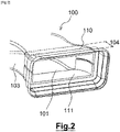
- the figure 1 represents a conduit 100 such as for example used between an HVAC system and an air vent of a motor vehicle.
- the conduit 100 can more broadly be a conduit for the circulation of any gaseous fluid.
- Conduit 100 includes an inlet opening 101 and an outlet opening 102 for fluid.
- the outlet opening 102 is here located opposite the inlet opening 101 which is close to a source of acoustic emission.
- the conduit 100 comprises, on at least a portion of conduit 104, in particular close to the outlet opening 102, an internal wall 103 of solid plastic material devoid of any side opening, that is to say that the wall 103 internal has no perforations, holes, lumens or drilling.
- the internal wall 103 is thus globally impermeable to the fluid flowing in the conduit 100, this fluid being mainly air in the present embodiment.
- Such a conduit is preferably made of plastic material. It is advantageously produced by extrusion blow molding of a polymer such as low or high density polyethylene (LDPE or HDPE, also known by their acronyms in English LDPE and HDPE), the conduit then being formed in a single part.
- LDPE or HDPE low or high density polyethylene
- the pipe 100 can also be produced, in particular in LDPE or HDPE, by injection molding, or extrusion blow molding.
- the duct 100 can advantageously consist of two half-ducts, connected for example by a hinge and secured by clipping.
- the duct 100 is generally of generally rectangular or cylindrical section, although it can take any other shape. It will be kept in mind that a rectangular or cylindrical section proves to be advantageous for the implementation of the process for preparing and installing the attenuation device described below.
- the duct 100 may comprise more than one inlet and outlet opening, as well as branches for example.
- the conduit 100 is equipped with an acoustic attenuation device 110 on the portion of the conduit 104.
- the acoustic attenuation device 110 is composed of a sound-absorbing coating 111, which is applied against the internal wall 103, preferably close to the outlet opening 102, that is to say for example on the aerator side in a vehicle.
- the internal wall 103 is covered by the sound-absorbing coating 111, which is thus placed inside the duct 100.
- the sound-absorbing coating 111 can also be applied against the internal wall 103, close to an inlet opening of the duct, that is to say for example on the “HVAC” side in a vehicle.
- the internal wall 103 is provided with the absorbent coating 111 only on part of the section of the portion of conduit 104, due to the geometry of the conduit 100.
- the internal wall 103 is covered by the absorbent coating 111 over the entire section of the conduit portion 104, that is to say that the absorbent coating 111 is arranged in an annular fashion inside the conduit 100, near of the outlet opening 102.
- the absorbent coating 111 is made in two parts, for practical manufacturing reasons.
- the two parts are here separated by a gap, which corresponds to a few millimeters in practice.
- This gap is due to the manufacturing tolerances of the parts of the absorbent covering 111, which allow inexpensive manufacturing, in comparison with manufacturing with tighter tolerances not allowing any gap to appear. However, such more precise manufacturing can of course also be implemented if necessary. Finally, it is specified that such a gap has no significant influence on the performance of the duct.
- the absorbent coating 111 is applied only to a zone close to the outlet opening 102.
- it is in particular close to the outlet of the duct 100 that one wishes to reduce the usually being close to a user.
- the application of the absorbent coating 111 in an area close to the opening, that is to say on the conduit portion 104, can simply be done manually.
- the zone close to the opening can be defined as the zone extending at most over about twenty centimeters inside the duct 100, from the outlet opening 102. This zone can also be defined with respect to the geometry of the section of this portion of duct.
- the depth over which this zone extends towards the inside of the duct 100 can be defined by a multiple of the hydraulic diameter of the section, when the latter is generally constant, which can be determined in a known manner.
- Such a multiplying factor is advantageously between 0.5 and 2.
- the zone can also be defined with respect to the overall geometry of the duct 100 on a portion close to the outlet 102.
- the zone close to the opening can in this case be defined empirically according to the overall geometry of the duct 100 on a portion close to the outlet 102.
- the absorbent coating 111 it is not excluded to apply the absorbent coating 111 on the entire internal surface of the duct 100, or on several parts of the internal surface of the duct 100 (for example at an inlet and an outlet, a branch of the conduit, etc.). In the latter case, the duct 100 then comprises several portions of duct provided with acoustic attenuation device 110. It is however preferred to apply the absorbent coating 111 only to portions close to an opening of the duct.
- the absorbent coating 111 is generally a synthetic foam with an open cellular structure, with a large pore size, that is to say preferably between 10 and 100 micrometers. According to a variant, the absorbent coating 111 is a stack of several layers of absorbent materials.
- the acoustic absorber has a surface mass of between 500 and 2000 g/m2, and preferably equal to 1350 g/m2.
- the density of the acoustic absorber is between 0.2 and 0.7 g/cm3, and more particularly 0.45 g/cm3.
- such a foam is thermoformable, so that it can be formed to the dimensions of the zone of the conduit 100 which must be covered by the absorbent coating 111.
- the foam is thermocompressed, so as to be reduced to a thickness of the order of 1 to 10 millimeters, in particular of the order of 1 to 4 millimeters, and preferably 1 to 3 millimeters.
- this thickness is of the order of 3 millimeters, which represents a compromise between high-performance sound insulation and acceptable bulk.
- the absorbent coating 111 applied to the internal wall 103 does not protrude inside the duct 100, the latter comprises a recess 105 at the level of the portion of the duct 104 covered by the absorbent coating 111, as illustrated in the picture 3 .
- the depth of the recess 105 in the direction of the thickness of the material constituting the duct 100 is generally equal to the thickness of the absorbent coating 111, so that the duct 100 retains a generally constant section on the duct portion 104.
- the recess 105 also forms a guide for the positioning of the absorbent liner 111 during the installation of the device 110, the recess 105 being the dimensions of the absorbent liner 111.
- the absorbent covering 111 is preferably fixed to the internal wall 103 by stapling, although it can also be glued. In the latter case, and in particular when the material of the internal wall 103 is polyethylene, it is advisable to select an adhesive allowing satisfactory adhesion and sufficiently durable bonding, given the low surface energy of polyethylene, whether the latter is foamed or not, as described below.
- the internal wall 103 is treated by flame treatment on the areas intended to be provided with the coating.
- absorbent 111 in order to increase the energy of the internal wall 103 on these areas, and thus allow bonding.
- the material of conduit 100 is a foamed polymer.
- a foamed polymer is for example obtained by way of chemical foaming, that is to say by incorporating a swelling agent into the base polymer, releasing a gas during the manufacture of the conduit 100.
- the material of the conduit 100 has a larger porous structure and becomes more flexible, allowing it to increase its sound absorption capacity.
- the porosity thus created is of the "closed” type, that is to say that the pores do not communicate with each other.
- the structure of such foamed plastics is generally of the sandwich type with two dense outer skins and an inner honeycomb structure.
- the material of conduit 100 can also be foamed physically, that is to say by injecting a pressurized gas during manufacture of the material.
- the foaming of the conduit 100 is preferably integral.
- the porosity of the material after foaming is advantageously between 0% and 30%, in particular when the material is produced by extrusion blow molding. Preferably, it is then between 10 and 20%, for example 15%.
- the porosity is preferably between 5% and 15%, preferably 10%.
- the softening of the duct 100 that is to say the lowering of its tensile modulus, in no way prevents the assembly operation on the vehicle, and allows a reliable fixing of the duct 100 on the HVAC system and the aerators, and, more broadly, allows the duct 100 to maintain its shape without difficulty under the effect of its weight, vibration, heat, etc.
- any combination of polymer with a blowing agent can be envisaged to produce the pipe 100
- the combinations involving low density polyethylene (LDPE) and high density (HDPE), with or without foaming show very satisfactory results in terms of acoustic attenuation.
- conduit 100 As shown in picture 2 , the portion of conduit 104 provided with absorbent coating 111 extending between 5 and 10 centimeters from the outlet opening 102. It is specified that a foamed conduit in the table below designates a conduit 100 foamed in its entirety , with an average porosity of approximately 15%, and not only on the conduit portion 104.
- the coating used in these tests has a thickness of 3 millimeters. It was placed near an outlet of the duct, at a depth of about 20 centimeters towards the inside of the duct.
- the measurements were carried out in a semi-anechoic chamber, for the frequency range 200 Hz to 5000 Hz.
- the foaming of the material of the conduit 100 allows a gain of about 0.5 dB for the same material
- the DECI-TEX ® D-TN90 absorbent coating allows a gain of between 2 and 3 dB while the 5015T absorbent coating allows a gain between 0.8 and 2 dB
- the replacement of HDPE by LDPE allows a gain of around 0.5 dB.
- the maximum acoustic gain obtained by virtue of the attenuation device 110 is therefore around 4 dB, compared with a pipe 100 made of simple HDPE.
- This scenario is obtained for a pipe 100 in foamed LDPE provided with a DECI-TEX ® D-TN90 absorbent coating.
- An acoustic gain of 4 dB means an acoustic pressure divided by 1.6, which translates into greatly improved acoustic comfort for a user of a vehicle having the invention.
- the invention also relates to a method 200 for preparing and installing the sound-absorbing coating 11 in the duct 100, as suggested by the above description.
- the steps of the method 200 will only be described briefly, so as to clarify the implementation of the conduit 100 according to the invention.
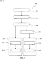
- the method 200 comprises according to a first variant the steps 201 to 203 described below, and according to a second variant the steps 201 to 204 described below, and optionally an initial step 205, as illustrated in the figure 4 .
- a step 201 of shaping the sound-absorbing coating 111 said coating is given its thickness and its final relief, so that it closely matches the internal wall 103 .
- This step is preferably a thermocompression step, when the sound-absorbing covering 111 is made of foam.
- a step 202 of cutting the absorbent coating to an internal dimension of the pipe the latter is made to the size of the pipe portion 104. It is possible to obtain a single coating portion, or several portions, which will be arranged on the inner wall 103 independently, juxtaposed or not.
- the coating portion or portions obtained previously are placed on the internal wall 103 of the conduit portion 104 intended to be covered by the sound-absorbing coating 111.
- the step 203 of positioning and fixing comprises a sub-step 2031 of positioning the covering portion against the internal wall 103, followed by a sub-step 2032 of stapling the covering portion while the latter is held against the internal wall 103 .
- step 203 of positioning and fixing is preceded by a step of preparing 204 a zone for bonding the coating to the internal wall 103, preferably carried out by flame treatment.
- the positioning and fixing step further comprises a sub-step 2033 of applying an adhesive, said adhesive being applied to a first so-called bonding face of the coating portion(s), and/or to the area of gluing of the inner wall 103, and a sub-step 2034 of positioning said bonding face on the inner wall 103.
- the conduit 100 can be obtained initial step 205 of manufacturing a conduit 100 by extrusion and blow molding, or by injection molding, or by injection and blow molding. This step is then implemented upstream of the other steps of the method 200.
- the method 200 is particularly simple, rapid and inexpensive to implement.
Landscapes
- Engineering & Computer Science (AREA)
- General Engineering & Computer Science (AREA)
- Mechanical Engineering (AREA)
- Chemical & Material Sciences (AREA)
- Combustion & Propulsion (AREA)
- Manufacturing & Machinery (AREA)
- Duct Arrangements (AREA)
- Pipe Accessories (AREA)
- Soundproofing, Sound Blocking, And Sound Damping (AREA)
Applications Claiming Priority (1)
| Application Number | Priority Date | Filing Date | Title |
|---|---|---|---|
| FR2102996A FR3121195B1 (fr) | 2021-03-25 | 2021-03-25 | Conduit de circulation d’un fluide gazeux comprenant un revêtement absorbant acoustique |
Publications (2)
| Publication Number | Publication Date |
|---|---|
| EP4063703A1 true EP4063703A1 (de) | 2022-09-28 |
| EP4063703B1 EP4063703B1 (de) | 2023-02-15 |
Family
ID=76601304
Family Applications (1)
| Application Number | Title | Priority Date | Filing Date |
|---|---|---|---|
| EP22164196.2A Active EP4063703B1 (de) | 2021-03-25 | 2022-03-24 | Strömungsleitung für ein gasförmiges fluid mit einer schallabsorbierenden verkleidung |
Country Status (2)
| Country | Link |
|---|---|
| EP (1) | EP4063703B1 (de) |
| FR (1) | FR3121195B1 (de) |
Citations (6)
| Publication number | Priority date | Publication date | Assignee | Title |
|---|---|---|---|---|
| US4615411A (en) * | 1982-05-27 | 1986-10-07 | Dynamit Nobel Ag | Sound-insulated flow duct and process for the manufacture thereof |
| EP0338908A1 (de) * | 1988-04-22 | 1989-10-25 | Regie Nationale Des Usines Renault | Luftleitungsrohr, insbesondere für die Klimaanlage von Fahrzeugen |
| FR2712851A1 (fr) * | 1993-11-23 | 1995-06-02 | Illbruck Sa | Conduit de ventilation comportant un atténuateur de bruit en mousse. |
| WO1997028397A1 (fr) * | 1996-02-01 | 1997-08-07 | Illbruck S.A. | Conduit d'air notamment pour vehicule automobile et son procede de montage |
| FR2920346A1 (fr) * | 2007-08-27 | 2009-03-06 | Peugeot Citroen Automobiles Sa | Systeme d'aeration pour un vehicule |
| EP2803515A1 (de) * | 2013-05-14 | 2014-11-19 | Jsp Corporation | Kanal |
-
2021
- 2021-03-25 FR FR2102996A patent/FR3121195B1/fr active Active
-
2022
- 2022-03-24 EP EP22164196.2A patent/EP4063703B1/de active Active
Patent Citations (6)
| Publication number | Priority date | Publication date | Assignee | Title |
|---|---|---|---|---|
| US4615411A (en) * | 1982-05-27 | 1986-10-07 | Dynamit Nobel Ag | Sound-insulated flow duct and process for the manufacture thereof |
| EP0338908A1 (de) * | 1988-04-22 | 1989-10-25 | Regie Nationale Des Usines Renault | Luftleitungsrohr, insbesondere für die Klimaanlage von Fahrzeugen |
| FR2712851A1 (fr) * | 1993-11-23 | 1995-06-02 | Illbruck Sa | Conduit de ventilation comportant un atténuateur de bruit en mousse. |
| WO1997028397A1 (fr) * | 1996-02-01 | 1997-08-07 | Illbruck S.A. | Conduit d'air notamment pour vehicule automobile et son procede de montage |
| FR2920346A1 (fr) * | 2007-08-27 | 2009-03-06 | Peugeot Citroen Automobiles Sa | Systeme d'aeration pour un vehicule |
| EP2803515A1 (de) * | 2013-05-14 | 2014-11-19 | Jsp Corporation | Kanal |
Non-Patent Citations (1)
| Title |
|---|
| MAAGTECHNIC SA: "ISOLATION ACOUSTIQUE", 30 June 2016 (2016-06-30), pages 1 - 20, XP055862521, Retrieved from the Internet <URL:https://maagtechnic.ch/content/dam/ch/pdf/elastomertechnik/Schallschutz_f.pdf> [retrieved on 20211117] * |
Also Published As
| Publication number | Publication date |
|---|---|
| FR3121195B1 (fr) | 2023-11-24 |
| EP4063703B1 (de) | 2023-02-15 |
| FR3121195A1 (fr) | 2022-09-30 |
Similar Documents
| Publication | Publication Date | Title |
|---|---|---|
| EP3916717B1 (de) | Schalldämmende wabenstruktur mit einer membran, die mit einem rohr versehen ist, das für die verarbeitung verschiedener akustischer frequenzen konfiguriert ist, verfahren zur herstellung einer solchen schalldämmenden wabenstruktur und entsprechendes werkzeug | |
| EP3868602B1 (de) | Kopfstütze, die mindestens eine lautsprecherbox umfasst | |
| FR2981049A1 (fr) | Procede de fabrication d'un panneau d'absorption acoustique | |
| FR3111002A1 (fr) | Procédé de fabrication d'une structure alvéolaire d’insonorisation incluant un diaphragme, et structure alvéolaire d’insonorisation obtenue | |
| EP3902696A1 (de) | Kraftfahrzeugstruktur | |
| EP3434529A1 (de) | Schalldämmelement für kraftfahrzeug, und entsprechendes herstellungsverfahren | |
| EP4063703B1 (de) | Strömungsleitung für ein gasförmiges fluid mit einer schallabsorbierenden verkleidung | |
| FR2925142A1 (fr) | Conduite d'air du bruit et procede de fabrication d'une conduite d'air amortissant du bruit | |
| EP3922494B1 (de) | Luftverteilungsschlauch für einen hvac-kreislauf eines fahrzeugs | |
| FR2665996A1 (fr) | Accessoire pour ameliorer la sonorite dans un vehicule automobile. | |
| EP3619068A1 (de) | Poröser lufteinlasskanal für ein hlk-system | |
| FR2876172A1 (fr) | Dispositif d'attenuation acoustique d'un conduit de ventilation d'un vehicule automobile et procede de realisation d'un tel dispositif | |
| EP3634712B1 (de) | Verfahren zur herstellung eines lufteinlasskanals | |
| EP0657325B1 (de) | Vorgeformte Abdichtungstrennwand für Kraftfahrzeuge mit einer Aufnahme für Lautsprecher | |
| EP1520772A1 (de) | Unterbauabweiser mit Lärmschutzeigenschaften | |
| EP1474314B1 (de) | Verfahren zur schalldämpfung, schalldämpfungselement und entsprechende anordnung | |
| WO2021084179A1 (fr) | Paroi poreuse et boitier d'installation de chauffage et/ou ventilation et/ou climatisation correspondant | |
| FR3052718B1 (fr) | Procede de fabrication d'une piece d'equipement automobile et piece associee | |
| FR2897023A1 (fr) | Coussin d'element de siege de vehicule automobile et procede de fabrication d'un tel coussin | |
| FR2893394A1 (fr) | Organe directionnel d'ejection d'air | |
| FR3128775A1 (fr) | Conduit de diffusion d’air à performances acoustiques élevées, en particulier pour véhicule automobile | |
| FR3152740A1 (fr) | Console centrale pour habitacle de véhicule automobile | |
| FR2832562A1 (fr) | Structure d'isolement pour groupe moto-ventilateur et support realise selon ladite structure | |
| FR3086210A1 (fr) | Boitier d'une installation de chauffage et/ou ventilation et/ou climatisation pour vehicule automobile et procede de fabrication | |
| EP2804732B1 (de) | Verfahren zur herstellung einer motorfahrzeug-innenausstattungsstruktur und zugehörige fertigungsanlagen |
Legal Events
| Date | Code | Title | Description |
|---|---|---|---|
| PUAI | Public reference made under article 153(3) epc to a published international application that has entered the european phase |
Free format text: ORIGINAL CODE: 0009012 |
|
| STAA | Information on the status of an ep patent application or granted ep patent |
Free format text: STATUS: THE APPLICATION HAS BEEN PUBLISHED |
|
| AK | Designated contracting states |
Kind code of ref document: A1 Designated state(s): AL AT BE BG CH CY CZ DE DK EE ES FI FR GB GR HR HU IE IS IT LI LT LU LV MC MK MT NL NO PL PT RO RS SE SI SK SM TR |
|
| STAA | Information on the status of an ep patent application or granted ep patent |
Free format text: STATUS: REQUEST FOR EXAMINATION WAS MADE |
|
| 17P | Request for examination filed |
Effective date: 20221005 |
|
| RBV | Designated contracting states (corrected) |
Designated state(s): AL AT BE BG CH CY CZ DE DK EE ES FI FR GB GR HR HU IE IS IT LI LT LU LV MC MK MT NL NO PL PT RO RS SE SI SK SM TR |
|
| GRAP | Despatch of communication of intention to grant a patent |
Free format text: ORIGINAL CODE: EPIDOSNIGR1 |
|
| STAA | Information on the status of an ep patent application or granted ep patent |
Free format text: STATUS: GRANT OF PATENT IS INTENDED |
|
| INTG | Intention to grant announced |
Effective date: 20221125 |
|
| RIC1 | Information provided on ipc code assigned before grant |
Ipc: F24F 13/02 20060101ALI20221114BHEP Ipc: F24F 13/24 20060101ALI20221114BHEP Ipc: F16L 55/033 20060101ALI20221114BHEP Ipc: B60H 1/00 20060101ALI20221114BHEP Ipc: F16L 9/21 20060101AFI20221114BHEP |
|
| GRAS | Grant fee paid |
Free format text: ORIGINAL CODE: EPIDOSNIGR3 |
|
| GRAA | (expected) grant |
Free format text: ORIGINAL CODE: 0009210 |
|
| STAA | Information on the status of an ep patent application or granted ep patent |
Free format text: STATUS: THE PATENT HAS BEEN GRANTED |
|
| AK | Designated contracting states |
Kind code of ref document: B1 Designated state(s): AL AT BE BG CH CY CZ DE DK EE ES FI FR GB GR HR HU IE IS IT LI LT LU LV MC MK MT NL NO PL PT RO RS SE SI SK SM TR |
|
| REG | Reference to a national code |
Ref country code: CH Ref legal event code: EP Ref country code: GB Ref legal event code: FG4D Free format text: NOT ENGLISH |
|
| REG | Reference to a national code |
Ref country code: DE Ref legal event code: R096 Ref document number: 602022000010 Country of ref document: DE |
|
| REG | Reference to a national code |
Ref country code: AT Ref legal event code: REF Ref document number: 1548398 Country of ref document: AT Kind code of ref document: T Effective date: 20230315 Ref country code: IE Ref legal event code: FG4D Free format text: LANGUAGE OF EP DOCUMENT: FRENCH |
|
| REG | Reference to a national code |
Ref country code: LT Ref legal event code: MG9D |
|
| REG | Reference to a national code |
Ref country code: NL Ref legal event code: MP Effective date: 20230215 |
|
| P01 | Opt-out of the competence of the unified patent court (upc) registered |
Effective date: 20230530 |
|
| REG | Reference to a national code |
Ref country code: AT Ref legal event code: MK05 Ref document number: 1548398 Country of ref document: AT Kind code of ref document: T Effective date: 20230215 |
|
| PG25 | Lapsed in a contracting state [announced via postgrant information from national office to epo] |
Ref country code: RS Free format text: LAPSE BECAUSE OF FAILURE TO SUBMIT A TRANSLATION OF THE DESCRIPTION OR TO PAY THE FEE WITHIN THE PRESCRIBED TIME-LIMIT Effective date: 20230215 Ref country code: PT Free format text: LAPSE BECAUSE OF FAILURE TO SUBMIT A TRANSLATION OF THE DESCRIPTION OR TO PAY THE FEE WITHIN THE PRESCRIBED TIME-LIMIT Effective date: 20230615 Ref country code: NO Free format text: LAPSE BECAUSE OF FAILURE TO SUBMIT A TRANSLATION OF THE DESCRIPTION OR TO PAY THE FEE WITHIN THE PRESCRIBED TIME-LIMIT Effective date: 20230515 Ref country code: NL Free format text: LAPSE BECAUSE OF FAILURE TO SUBMIT A TRANSLATION OF THE DESCRIPTION OR TO PAY THE FEE WITHIN THE PRESCRIBED TIME-LIMIT Effective date: 20230215 Ref country code: LV Free format text: LAPSE BECAUSE OF FAILURE TO SUBMIT A TRANSLATION OF THE DESCRIPTION OR TO PAY THE FEE WITHIN THE PRESCRIBED TIME-LIMIT Effective date: 20230215 Ref country code: LT Free format text: LAPSE BECAUSE OF FAILURE TO SUBMIT A TRANSLATION OF THE DESCRIPTION OR TO PAY THE FEE WITHIN THE PRESCRIBED TIME-LIMIT Effective date: 20230215 Ref country code: HR Free format text: LAPSE BECAUSE OF FAILURE TO SUBMIT A TRANSLATION OF THE DESCRIPTION OR TO PAY THE FEE WITHIN THE PRESCRIBED TIME-LIMIT Effective date: 20230215 Ref country code: ES Free format text: LAPSE BECAUSE OF FAILURE TO SUBMIT A TRANSLATION OF THE DESCRIPTION OR TO PAY THE FEE WITHIN THE PRESCRIBED TIME-LIMIT Effective date: 20230215 Ref country code: AT Free format text: LAPSE BECAUSE OF FAILURE TO SUBMIT A TRANSLATION OF THE DESCRIPTION OR TO PAY THE FEE WITHIN THE PRESCRIBED TIME-LIMIT Effective date: 20230215 |
|
| PG25 | Lapsed in a contracting state [announced via postgrant information from national office to epo] |
Ref country code: SE Free format text: LAPSE BECAUSE OF FAILURE TO SUBMIT A TRANSLATION OF THE DESCRIPTION OR TO PAY THE FEE WITHIN THE PRESCRIBED TIME-LIMIT Effective date: 20230215 Ref country code: PL Free format text: LAPSE BECAUSE OF FAILURE TO SUBMIT A TRANSLATION OF THE DESCRIPTION OR TO PAY THE FEE WITHIN THE PRESCRIBED TIME-LIMIT Effective date: 20230215 Ref country code: IS Free format text: LAPSE BECAUSE OF FAILURE TO SUBMIT A TRANSLATION OF THE DESCRIPTION OR TO PAY THE FEE WITHIN THE PRESCRIBED TIME-LIMIT Effective date: 20230615 Ref country code: GR Free format text: LAPSE BECAUSE OF FAILURE TO SUBMIT A TRANSLATION OF THE DESCRIPTION OR TO PAY THE FEE WITHIN THE PRESCRIBED TIME-LIMIT Effective date: 20230516 Ref country code: FI Free format text: LAPSE BECAUSE OF FAILURE TO SUBMIT A TRANSLATION OF THE DESCRIPTION OR TO PAY THE FEE WITHIN THE PRESCRIBED TIME-LIMIT Effective date: 20230215 |
|
| PG25 | Lapsed in a contracting state [announced via postgrant information from national office to epo] |
Ref country code: SM Free format text: LAPSE BECAUSE OF FAILURE TO SUBMIT A TRANSLATION OF THE DESCRIPTION OR TO PAY THE FEE WITHIN THE PRESCRIBED TIME-LIMIT Effective date: 20230215 Ref country code: RO Free format text: LAPSE BECAUSE OF FAILURE TO SUBMIT A TRANSLATION OF THE DESCRIPTION OR TO PAY THE FEE WITHIN THE PRESCRIBED TIME-LIMIT Effective date: 20230215 Ref country code: EE Free format text: LAPSE BECAUSE OF FAILURE TO SUBMIT A TRANSLATION OF THE DESCRIPTION OR TO PAY THE FEE WITHIN THE PRESCRIBED TIME-LIMIT Effective date: 20230215 Ref country code: DK Free format text: LAPSE BECAUSE OF FAILURE TO SUBMIT A TRANSLATION OF THE DESCRIPTION OR TO PAY THE FEE WITHIN THE PRESCRIBED TIME-LIMIT Effective date: 20230215 Ref country code: CZ Free format text: LAPSE BECAUSE OF FAILURE TO SUBMIT A TRANSLATION OF THE DESCRIPTION OR TO PAY THE FEE WITHIN THE PRESCRIBED TIME-LIMIT Effective date: 20230215 |
|
| REG | Reference to a national code |
Ref country code: DE Ref legal event code: R097 Ref document number: 602022000010 Country of ref document: DE |
|
| PG25 | Lapsed in a contracting state [announced via postgrant information from national office to epo] |
Ref country code: SK Free format text: LAPSE BECAUSE OF FAILURE TO SUBMIT A TRANSLATION OF THE DESCRIPTION OR TO PAY THE FEE WITHIN THE PRESCRIBED TIME-LIMIT Effective date: 20230215 |
|
| PLBE | No opposition filed within time limit |
Free format text: ORIGINAL CODE: 0009261 |
|
| STAA | Information on the status of an ep patent application or granted ep patent |
Free format text: STATUS: NO OPPOSITION FILED WITHIN TIME LIMIT |
|
| PG25 | Lapsed in a contracting state [announced via postgrant information from national office to epo] |
Ref country code: MC Free format text: LAPSE BECAUSE OF FAILURE TO SUBMIT A TRANSLATION OF THE DESCRIPTION OR TO PAY THE FEE WITHIN THE PRESCRIBED TIME-LIMIT Effective date: 20230215 |
|
| 26N | No opposition filed |
Effective date: 20231116 |
|
| PG25 | Lapsed in a contracting state [announced via postgrant information from national office to epo] |
Ref country code: SI Free format text: LAPSE BECAUSE OF FAILURE TO SUBMIT A TRANSLATION OF THE DESCRIPTION OR TO PAY THE FEE WITHIN THE PRESCRIBED TIME-LIMIT Effective date: 20230215 Ref country code: MC Free format text: LAPSE BECAUSE OF FAILURE TO SUBMIT A TRANSLATION OF THE DESCRIPTION OR TO PAY THE FEE WITHIN THE PRESCRIBED TIME-LIMIT Effective date: 20230215 |
|
| PG25 | Lapsed in a contracting state [announced via postgrant information from national office to epo] |
Ref country code: IT Free format text: LAPSE BECAUSE OF FAILURE TO SUBMIT A TRANSLATION OF THE DESCRIPTION OR TO PAY THE FEE WITHIN THE PRESCRIBED TIME-LIMIT Effective date: 20230215 |
|
| PG25 | Lapsed in a contracting state [announced via postgrant information from national office to epo] |
Ref country code: BG Free format text: LAPSE BECAUSE OF FAILURE TO SUBMIT A TRANSLATION OF THE DESCRIPTION OR TO PAY THE FEE WITHIN THE PRESCRIBED TIME-LIMIT Effective date: 20230215 |
|
| PG25 | Lapsed in a contracting state [announced via postgrant information from national office to epo] |
Ref country code: LU Free format text: LAPSE BECAUSE OF NON-PAYMENT OF DUE FEES Effective date: 20240324 |
|
| PG25 | Lapsed in a contracting state [announced via postgrant information from national office to epo] |
Ref country code: LU Free format text: LAPSE BECAUSE OF NON-PAYMENT OF DUE FEES Effective date: 20240324 Ref country code: BG Free format text: LAPSE BECAUSE OF FAILURE TO SUBMIT A TRANSLATION OF THE DESCRIPTION OR TO PAY THE FEE WITHIN THE PRESCRIBED TIME-LIMIT Effective date: 20230215 |
|
| REG | Reference to a national code |
Ref country code: BE Ref legal event code: MM Effective date: 20240331 |
|
| PG25 | Lapsed in a contracting state [announced via postgrant information from national office to epo] |
Ref country code: BE Free format text: LAPSE BECAUSE OF NON-PAYMENT OF DUE FEES Effective date: 20240331 |
|
| PG25 | Lapsed in a contracting state [announced via postgrant information from national office to epo] |
Ref country code: IE Free format text: LAPSE BECAUSE OF NON-PAYMENT OF DUE FEES Effective date: 20240324 |
|
| PG25 | Lapsed in a contracting state [announced via postgrant information from national office to epo] |
Ref country code: IE Free format text: LAPSE BECAUSE OF NON-PAYMENT OF DUE FEES Effective date: 20240324 Ref country code: BE Free format text: LAPSE BECAUSE OF NON-PAYMENT OF DUE FEES Effective date: 20240331 |
|
| PGFP | Annual fee paid to national office [announced via postgrant information from national office to epo] |
Ref country code: DE Payment date: 20250327 Year of fee payment: 4 |
|
| PG25 | Lapsed in a contracting state [announced via postgrant information from national office to epo] |
Ref country code: CY Free format text: LAPSE BECAUSE OF FAILURE TO SUBMIT A TRANSLATION OF THE DESCRIPTION OR TO PAY THE FEE WITHIN THE PRESCRIBED TIME-LIMIT; INVALID AB INITIO Effective date: 20220324 |
|
| REG | Reference to a national code |
Ref country code: CH Ref legal event code: H13 Free format text: ST27 STATUS EVENT CODE: U-0-0-H10-H13 (AS PROVIDED BY THE NATIONAL OFFICE) Effective date: 20251023 |
|
| PG25 | Lapsed in a contracting state [announced via postgrant information from national office to epo] |
Ref country code: TR Free format text: LAPSE BECAUSE OF FAILURE TO SUBMIT A TRANSLATION OF THE DESCRIPTION OR TO PAY THE FEE WITHIN THE PRESCRIBED TIME-LIMIT Effective date: 20230215 |
|
| PG25 | Lapsed in a contracting state [announced via postgrant information from national office to epo] |
Ref country code: CH Free format text: LAPSE BECAUSE OF NON-PAYMENT OF DUE FEES Effective date: 20250331 |
|
| PGFP | Annual fee paid to national office [announced via postgrant information from national office to epo] |
Ref country code: FR Payment date: 20260324 Year of fee payment: 5 |