EP4063741B1 - Appareil de cuisson - Google Patents
Appareil de cuisson Download PDFInfo
- Publication number
- EP4063741B1 EP4063741B1 EP21781535.6A EP21781535A EP4063741B1 EP 4063741 B1 EP4063741 B1 EP 4063741B1 EP 21781535 A EP21781535 A EP 21781535A EP 4063741 B1 EP4063741 B1 EP 4063741B1
- Authority
- EP
- European Patent Office
- Prior art keywords
- flow path
- region
- air
- cooking appliance
- opening portion
- Prior art date
- Legal status (The legal status is an assumption and is not a legal conclusion. Google has not performed a legal analysis and makes no representation as to the accuracy of the status listed.)
- Active
Links
Images


Classifications
-
- F—MECHANICAL ENGINEERING; LIGHTING; HEATING; WEAPONS; BLASTING
- F24—HEATING; RANGES; VENTILATING
- F24C—DOMESTIC STOVES OR RANGES ; DETAILS OF DOMESTIC STOVES OR RANGES, OF GENERAL APPLICATION
- F24C15/00—Details
- F24C15/32—Arrangements of ducts for hot gases, e.g. in or around baking ovens
- F24C15/322—Arrangements of ducts for hot gases, e.g. in or around baking ovens with forced circulation
-
- F—MECHANICAL ENGINEERING; LIGHTING; HEATING; WEAPONS; BLASTING
- F24—HEATING; RANGES; VENTILATING
- F24C—DOMESTIC STOVES OR RANGES ; DETAILS OF DOMESTIC STOVES OR RANGES, OF GENERAL APPLICATION
- F24C15/00—Details
- F24C15/006—Arrangements for circulation of cooling air
-
- A—HUMAN NECESSITIES
- A47—FURNITURE; DOMESTIC ARTICLES OR APPLIANCES; COFFEE MILLS; SPICE MILLS; SUCTION CLEANERS IN GENERAL
- A47J—KITCHEN EQUIPMENT; COFFEE MILLS; SPICE MILLS; APPARATUS FOR MAKING BEVERAGES
- A47J37/00—Baking; Roasting; Grilling; Frying
- A47J37/06—Roasters; Grills; Sandwich grills
- A47J37/0623—Small-size cooking ovens, i.e. defining an at least partially closed cooking cavity
- A47J37/0629—Small-size cooking ovens, i.e. defining an at least partially closed cooking cavity with electric heating elements
- A47J37/0641—Small-size cooking ovens, i.e. defining an at least partially closed cooking cavity with electric heating elements with forced air circulation, e.g. air fryers
-
- F—MECHANICAL ENGINEERING; LIGHTING; HEATING; WEAPONS; BLASTING
- F24—HEATING; RANGES; VENTILATING
- F24C—DOMESTIC STOVES OR RANGES ; DETAILS OF DOMESTIC STOVES OR RANGES, OF GENERAL APPLICATION
- F24C15/00—Details
- F24C15/005—Coatings for ovens
-
- F—MECHANICAL ENGINEERING; LIGHTING; HEATING; WEAPONS; BLASTING
- F24—HEATING; RANGES; VENTILATING
- F24C—DOMESTIC STOVES OR RANGES ; DETAILS OF DOMESTIC STOVES OR RANGES, OF GENERAL APPLICATION
- F24C15/00—Details
- F24C15/06—Ornamental features, e.g. grate fronts or surrounds
-
- F—MECHANICAL ENGINEERING; LIGHTING; HEATING; WEAPONS; BLASTING
- F24—HEATING; RANGES; VENTILATING
- F24C—DOMESTIC STOVES OR RANGES ; DETAILS OF DOMESTIC STOVES OR RANGES, OF GENERAL APPLICATION
- F24C15/00—Details
- F24C15/08—Foundations or supports plates; Legs or pillars; Casings; Wheels
-
- F—MECHANICAL ENGINEERING; LIGHTING; HEATING; WEAPONS; BLASTING
- F24—HEATING; RANGES; VENTILATING
- F24C—DOMESTIC STOVES OR RANGES ; DETAILS OF DOMESTIC STOVES OR RANGES, OF GENERAL APPLICATION
- F24C15/00—Details
- F24C15/20—Removing cooking fumes
- F24C15/2007—Removing cooking fumes from oven cavities
-
- F—MECHANICAL ENGINEERING; LIGHTING; HEATING; WEAPONS; BLASTING
- F24—HEATING; RANGES; VENTILATING
- F24C—DOMESTIC STOVES OR RANGES ; DETAILS OF DOMESTIC STOVES OR RANGES, OF GENERAL APPLICATION
- F24C15/00—Details
- F24C15/32—Arrangements of ducts for hot gases, e.g. in or around baking ovens
-
- F—MECHANICAL ENGINEERING; LIGHTING; HEATING; WEAPONS; BLASTING
- F24—HEATING; RANGES; VENTILATING
- F24C—DOMESTIC STOVES OR RANGES ; DETAILS OF DOMESTIC STOVES OR RANGES, OF GENERAL APPLICATION
- F24C15/00—Details
- F24C15/32—Arrangements of ducts for hot gases, e.g. in or around baking ovens
- F24C15/322—Arrangements of ducts for hot gases, e.g. in or around baking ovens with forced circulation
- F24C15/325—Arrangements of ducts for hot gases, e.g. in or around baking ovens with forced circulation electrically-heated
-
- F—MECHANICAL ENGINEERING; LIGHTING; HEATING; WEAPONS; BLASTING
- F24—HEATING; RANGES; VENTILATING
- F24C—DOMESTIC STOVES OR RANGES ; DETAILS OF DOMESTIC STOVES OR RANGES, OF GENERAL APPLICATION
- F24C3/00—Stoves or ranges for gaseous fuels
- F24C3/12—Arrangement or mounting of control or safety devices
- F24C3/126—Arrangement or mounting of control or safety devices on ranges
-
- F—MECHANICAL ENGINEERING; LIGHTING; HEATING; WEAPONS; BLASTING
- F24—HEATING; RANGES; VENTILATING
- F24C—DOMESTIC STOVES OR RANGES ; DETAILS OF DOMESTIC STOVES OR RANGES, OF GENERAL APPLICATION
- F24C5/00—Stoves or ranges for liquid fuels
- F24C5/16—Arrangement or mounting of control or safety devices
-
- F—MECHANICAL ENGINEERING; LIGHTING; HEATING; WEAPONS; BLASTING
- F24—HEATING; RANGES; VENTILATING
- F24C—DOMESTIC STOVES OR RANGES ; DETAILS OF DOMESTIC STOVES OR RANGES, OF GENERAL APPLICATION
- F24C7/00—Stoves or ranges heated by electric energy
- F24C7/08—Arrangement or mounting of control or safety devices
- F24C7/082—Arrangement or mounting of control or safety devices on ranges, e.g. control panels, illumination
- F24C7/085—Arrangement or mounting of control or safety devices on ranges, e.g. control panels, illumination on baking ovens
Definitions
- the disclosure relates to a cooking appliance, and more specifically, to a cooking appliance with an improved structure.
- a cooking appliance is a household appliance equipped with a cooking chamber, a heating device for applying heat to the cooking chamber, and a circulation device for circulating heat generated by the heating device in the cooking chamber and cooks food.
- the cooking appliance may be classified into an electric type cooking appliance, a gas type cooking appliance, and an electronic type cooking appliance according to a heating source of the heating device.
- an electric oven may use an electric heater as a heating source
- a gas oven may use heat generated by gas as a heating source
- a microwave oven may use frictional heat of water molecules due to high frequency as a heating source.
- the cooking appliance may be provided with a control panel at one of front and upper surfaces of a main body.
- the control panel may be provided with a number of buttons, a keypad, a knobs, etc. configured to set a cooking mode desired by a user or set various conditions required for cooking.
- the cooking appliance may include a knob holder surrounding the knob, and may include a glass panel forming the front surface of the control panel.
- US 2015/241069 A1 discloses a cooking oven configured to cool the exterior surface of the oven.
- the cooking appliance can be provided with improved air fluidity at an upper portion of a case for efficient cooling of electric components disposed on the upper portion of the case.
- the cooking appliance can be provided with an enhanced aesthetic sense by improving the shape of a discharge portion through which air flowing from an upper portion of a case is discharged.
- the cooking appliance can secure the stiffness of a cooking chamber by improving a welding structure of the cooking chamber, and improve the quality of enamel on the cooking chamber.
- first and second may be used to explain various components, but the components are not limited by the terms. The terms are only for the purpose of distinguishing a component from another. Thus, a first element, component, region, layer or section discussed below could be termed a second element, component, region, layer or section without departing from the teachings of the disclosure. Descriptions shall be understood as to include any and all combinations of one or more of the associated listed items when the items are described by using the conjunctive term " ⁇ and/or ⁇ ,” or the like.
- FIG. 1 is a view illustrating a cooking appliance according to an embodiment of the disclosure.
- FIG. 2 is a view illustrating a state of the cooking appliance shown in FIG. 1 in which a door is open.
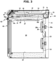
- FIG. 3 is a side cross-sectional view illustrating the cooking appliance shown in FIG. 1 .
- a cooking appliance 1 according to an embodiment of the disclosure will be described with reference to FIGS. 1 to 3 .
- the cooking appliance 1 includes a main body 10 including an inner case 11 in which a cooking chamber 20 is formed and an outer case 12 coupled to the outside of the inner case 11 to form the external appearance of the cooking appliance 1.
- the inner case 11 and the outer case 12 may each have a substantially box shape with an open front.
- the outer case 12 may include a front panel 13 forming the front surface of the main body 10, a side panel 14 forming the side surface of the main body 10, and a rear panel 15 forming the rear surface of the main body 10.
- the front panel 13 may be formed with a main body opening 13a, and the main body opening 13a may allow a front surface of the cooking chamber 20 provided inside the main body 10 to be opened.
- the front panel 13 may be provided at a front upper portion thereof with a control panel 50 that covers a front surface of a machine room 40.
- the cooking chamber 20 may be formed by a top plate 21, a bottom plate 22, both side plates 23 and a rear plate 24.
- the cooking chamber 20 is a cooking space that has a front surface openable through the opening of the front panel 13 so that food may be put in and out.
- the both side plates 23 may be provided with a plurality of supports 23a formed on inner surfaces thereof. At least one detachable rack 26 on which food may be placed may be mounted on the plurality of supports 23a.
- Rails may be installed on the plurality of supports 23a so that the rack 26 is slidable. A user may move the rack 26 through the rail (not shown) to take out or place food.
- a divider capable of dividing the cooking chamber 20 into a plurality of cooking chambers may be detachably mounted on the plurality of supports 23a.
- the plurality of cooking chambers 20 divided by the divider do not need to have the same size, and each size may be different from each other.
- the user may utilize the divided spaces of the plurality of cooking chamber 20 in various uses according to the intention.
- the divider may be formed of an insulating material to insulate each cooking chamber 20.
- the cooking chamber 20 may be provided with a first heating device 27 for heating food, and the first heating device 27 may be provided as a heater.
- the first heating device 27 may be an electric heater including an electric resistor.
- the disclosure is not limited thereto, and the first heating device 27 may be a gas heater that generates heat by burning gas.
- the cooking appliance 1 may include an electric oven and a gas oven.
- the rear plate 24 of the cooking chamber 20 may be provided with a circulation fan 28 that circulates air in the cooking chamber 20 so that food is evenly heated, and a circulation motor 28a that drives the circulation fan 28.
- the circulation fan 28 may be provided on a front side thereof with a fan cover 28b that covers the circulation fan 28, and the fan cover 28b may be formed with a cover opening 28c formed to allow air to flow therethrough.
- Electric components for driving the cooking appliance 1 may be disposed in the machine room 40.
- the machine room 40 may be disposed above the cooking chamber 20.
- a heat insulating material 29 that insulates the machine room 40 and the cooking chamber 20 may be provided between the machine room 40 and the cooking chamber 20 to prevent heat from the cooking chamber 20 from being transmitted to the machine room 40.
- the heat insulating material 29 may not only cover a region between the machine room 40 and the cooking chamber 20, but also entirely cover the outer side of the cooking chamber 20 so that heat from the cooking chamber 20 is not transmitted to the outside of the cooking appliance 1.
- the open front of the cooking chamber 20 is opened and closed by a door 60, and the door 60 may be coupled to the main body 10 by a hinge 61 provided at a lower portion the main body 10 so as to be rotated with respect to the main body 10.
- the door 60 rotatably coupled to the front surface of the main body 10 to open and close the cooking chamber 20 may be formed of a plurality of glasses.
- a handle 62 to be gripped by a user may be provided on a front upper portion of the door 60 to open and close the cooking chamber 20 by the door 60.
- the cooking appliance 1 may include a cooktop 30 provided on the upper portion of the cooking appliance 1 to heat a container containing food and placed thereon.
- the cooktop 30 may include a cooking surface 31 horizontally formed on an upper side of the cooktop 30.
- At least one heating portion 32 may be provided on the cooking surface 31.
- the container containing the cooking object may be placed in the heating portion 32 to thereby be directly heated.
- the cooktop 30 may include a second heating device 33 disposed below the cooking surface 31 and providing heat to the heating portion 32.
- the second heating device 33 may be provided corresponding in number to the number of the heating portions 32.
- the second heating device 33 may be disposed inside the machine room 40 below the cooktop 30.
- the second heating device 33 may be provided as a heater.
- the second heating device 33 may be an electric heater including an electric resistor.
- the disclosure is not limited thereto, and the cooktop 30 may be provided as an induction range, and in this case, the second heating device 33 may be provided as a high frequency induction heating device.
- the control panel 50 may be configured to control the first and second heating devices 27 and 33.
- the control panel 50 may be disposed on at least a portion of the main body 10. According to an embodiment of the disclosure, the control panel 50 may be disposed on the upper end of the front surface of the main body 10. However, the disclosure is not limited thereto, and the control panel 50 may be disposed on the upper surface of the main body 10 or may form one surface of the main body 10.
- the control panel 50 may include an exterior panel 53 forming the external appearance thereof.
- the exterior panel 53 may be formed of a glass material, but is not limited thereto.
- the control panel 50 may include a knob 51 capable of operating the cooking appliance 1.
- the knob 51 may be configured to operate the cooktop 30.
- the knobs 51 may be provided corresponding in number to the number of heating portions 32 of the cooktop 30.
- the control panel 50 may include an input device 52 capable of operating the cooking appliance 1.
- the input device 52 may be configured to operate the heater 27 of the cooking chamber 20.
- the input device 52 may be provided as a type that operates by being rotated, similar to the knob 51.
- the input device 52 may be provided as a button type input device that operates by being pressed, and as a touch screen type input device.
- a display module (not shown) may be mounted on the control panel 50.
- the display module may be provided to enable a touch input.
- the knob 51, the input device 52, and the display module may be disposed on the exterior panel 53.
- the machine room 40 may have a temperature rise by heat from various electric components (electric components except for a component denoted by a reference numeral 41 are omitted in the drawing) accommodated therein or from the second heating device 33, or may receive heat directly transferred from the cooking chamber 20.
- the cooking appliance 1 includes a blower device 70 capable of cooling the machine room 40 by circulating air around the machine room 40 and an intermediate flow path 80 formed to allow external air introduced through the blower device 70 to move therethrough.
- the intermediate flow path 80 is formed between the machine room 40 and the cooking chamber 20. Accordingly, heat generated in the cooking chamber 20 is prevented from being transferred to the machine room 40.
- the blower device 70 is disposed on the intermediate flow path 80 to circulate external air. Accordingly, heat generated in the cooking chamber 20 is provided to flow together with the external air circulating in the intermediate flow path 80 and prevented flowing to the machine room 40.
- the intermediate flow path 80 includes a first suction port 80a formed at the front end thereof.
- the blower device 70 is disposed at the rear end of the intermediate flow path 80. As the blower device 70 is driven, external air is caused to flow into the intermediate flow path 80 through the first suction port 80a and then flows into the blower device 70 along the intermediate flow path 80 to the outside of the cooking appliance 1.
- the first suction port 80a may be disposed between the upper end of the door 60 and the lower end of the machine room 40.
- the machine room 40 includes a second suction port 55 provided to circulate the air inside the machine room 40 to prevent the temperature of the electric component 41 from rising by the heat generated inside the machine room 40.
- the technical characteristics of air flow inside the machine room 40 will be described in detail below.
- the blower device 70 includes a blower fan 71 that causes air to flow.
- the second suction port 55 may be disposed on the control panel 50.
- the outside air introduced through the second suction port 55 cools the electric components 41 of the machine room 40 and flow into the intermediate flow path 80 and then into the blower device 70 along the intermediate flow path 80.
- the cooking appliance 1 may efficiently cool the electric components 41 of the machine room 40.
- the blower fan 71 may suction air in the axial direction and discharge the suctioned air in the radial direction. That is, the blower fan 71 according to the disclosure may be a centrifugal fan. Alternatively, the blower fan 71 may include an axial fan.
- the blower device 70 includes a discharge port 72 through which air introduced by the blower fan 71 is discharged.
- the discharge port 72 may be provided to be opened upward of the cooking appliance 1. Accordingly, the outside air introduced through first and second suction ports 81 and 55 flows into the intermediate flow path 80 or the machine room 40 to thereby be mixed on the intermediate flow path 80 and discharged outside of the cooking appliance 1 through the discharge port 72.
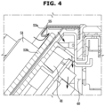
- FIG. 4 is an enlarged view showing a portion of FIG. 3
- FIG. 5 is a cross-sectional perspective view illustrating the machine room and the intermediate flow path shown in FIG. 3 .
- the second suction port 55 may be formed at an approximately central portion along the length direction of the control panel 50.
- the second suction port 55 may be located at an upper side of the input device 52.
- the second suction port 55 may be formed on a cutout region formed on the exterior panel 53.
- the exterior panel 53 may be formed by assembling an upper exterior panel 53a to a front exterior panel 53b, and the second suction port 55 may be formed at a separation between the upper exterior panel 53a and the front exterior panel 53b.
- the second suction port 55 may be positioned to correspond to the electric component 41 mounted on the control panel 50. Accordingly, air introduced through the second suction port 55 may efficiently cool the electric component 41.
- the second suction port 55 may be formed to face in the direction of gravity.
- the second suction port 55 may be formed to face downward. Accordingly, the inlet may be provided without being exposed to the user.
- Air introduced through the second suction port 55 is introduced into the machine room 40.
- the air introduced into the machine room 40 while flowing along the direction of gravity, performs heat exchanges with the electric component 41 mounted on the control panel 50 to thereby easily cool the electric component 41.
- Air introduced into the machine room 40 may cool the electric components 41 adjacent to the control panel 50.
- the disclosure is not limited thereto, and the second suction port 55 may be formed in another portion of the control panel 50 or may be disposed at one side of the front part of the machine room 40 rather than on the control panel 50.
- the second suction port 55 may cool the electric components 41 while heat-exchanging with other various electric components (not shown) arranged inside the machine room 40.
- heat generated from the second heating device (33 in FIG. 3 ) arranged inside the machine room 40 may be moved by the outside air introduced through the second suction port 55 and thus the heat generated from the second heating device 33 may be prevented from being transferred to the electric components 41 adjacent to the control panel 50 and other various electric components (not shown).
- the cooking appliance 1 includes a partition plate 100 that divides the machine room 40 from the intermediate flow path 80 in the upper side and lower side direction.
- the upper surface of the partition plate 100 may form a lower portion of the machine room 40, and the lower surface of the partition plate 100 may form an upper portion of the intermediate flow path 80.
- the partition plate 100 may form parts of each of the machine room 40 and the intermediate flow path 80.
- the partition plate 100 may be considered as a part of the machine room 40 or a part of the intermediate flow path 80.
- the partition plate 100 includes an opening portion 110 through which external air suctioned from the second suction port 55 flows into the intermediate flow path 80.
- the opening portion 110 is provided to communicate the machine room 40 with the intermediate flow path 80.
- An intake airflow generated from the blower device 70 may be transmitted to the machine room 40 through the opening portion 110.
- the machine room 40 is not separately provided with a blower fan for suctioning air to introduce outside air from the second suction port 55, the intake airflow generated from the blower device 70 is moved through the opening portion 110 into the machine room 40 so that air may be suctioned through the second suction port 55.
- the air suctioned through the second suction port 55 flows into the machine room 40 and performs heat exchange with the electric component 41 and then flows into the intermediate flow path 80 through the opening portion 110.
- the air flowing to the intermediate flow path 80 is moved together with air suctioned through the first suction port 80a and discharged to the outside of the cooking appliance 1 through the blower device 70.
- FIG. 6 is an exploded perspective view illustrating some components of the cooking appliance according to the embodiment of the disclosure
- FIG. 7 is a perspective view illustrating the interior of the machine room of the cooking appliance according to the embodiment of the disclosure.
- the intermediate flow path 80 may be disposed above the cooking chamber 20 and below the machine room 40.
- the intermediate flow path 80 may extend in a laterally asymmetrical shape in a front side and rear side direction.
- the intermediate flow path 80 may be formed asymmetrically with respect to a center X in the second direction B when viewed from the center X in the second direction B inside the intermediate flow path 80.
- the intermediate flow path 80 may not be formed in the entire area on the upper side the cooking chamber 20 due to the components of the cooking appliance 1 disposed on the upper side the cooking chamber 20 as described above.
- the intermediate flow path 80 is formed asymmetrically with respect to the center X in the second direction B.
- the intermediate flow path 80 may be formed to extend in the first direction A so as not to overlap the position where the cooking chamber discharge flow path 79 is disposed.
- the flow area of air in the intermediate flow path 80 may be provided to increase or decrease in the second direction. That is, the intermediate flow path 80 is provided to extend from a front end in the first direction A at which the first suction port 80a is formed to a rear end in the first direction A at which the blower device 70 is disposed, and the flow area of air inside the intermediate flow path 80 increases or decreases in the second direction B as the intermediate flow path 80 extends in the first direction A.
- the flow area of air inside the intermediate flow path 80 at the front end in the first direction A may be larger than the flow area of air inside the intermediate flow path 80 at the rear end in the first direction A.
- the flow area of air inside the intermediate flow path 80 may gradually decrease from the front end to the rear end in the first direction A.
- the flow area of air inside the intermediate flow path 80 may decrease in an asymmetrical manner in the second direction B with respect to the center X in the second direction B.
- the intermediate flow path 80 may include a first region 81 and a second region 82 arranged at one side and the opposite side with respect to the center X in the second direction B.
- the first suction ports 80a communicating with the outside may be disposed at a front end of the first region 81 and a front end of the second region 82, respectively. Outside air introduced from the first suction ports 80a may pass through the first region 81 and the second region 82 into the blower device 70.
- the total flow area of air in the first region 81 may be provided to be larger than the total flow area of air in the second region 82. This is because the cooking chamber discharge flow path 79 is disposed at a position corresponding to the second region 82 when viewed in the first direction A as described above, the second region 82 has a reduced area in the second direction B.
- the blower device 70 may be disposed on the first region 81. This is because, when viewed in the first direction A, the upper side of the cooking chamber 20 in the first region 81 does not have auxiliary components, the blower device 70 may be easily disposed on the first region 81.
- the disclosure is not limited thereto, and when auxiliary components are disposed on the upper side of the cooking chamber 20 in a region corresponding to the first region 81 when viewed in the first direction A, the blower device 70 may be disposed on the second region 82, and the total flow area of air in the first region 81 may be provided to be smaller than the total flow area of air in the second region 82.
- the sizes of the total flow areas of air in the first region 81 and the second region 82 and the location where the blower device 80 is disposed may vary depending on the arrangement of components on the upper side of the cooking chamber 20.
- the first region 81 may be provided to have a constant flow area of air in the intermediate flow path 80 in the first direction A.
- the second region 82 may be provided to have a flow area of air inside the intermediate flow path 80 in the first direction A that decreases as being directed toward the rear end in the first direction A.
- the intermediate flow path 80 may include a first wall 83 forming one side of the first region 81 and a second wall 84 forming one side of the second region 82.
- the first wall 83 and the second wall 84 may be provided to extend in the first direction A.
- the inclination angle of the first wall 83 with respect to the first direction A may be provided to be smaller than the inclination angle of the second wall 84 with respect to the first direction A. Accordingly, the flow area of air inside the second region 82 may be provided to be smaller than the flow area of air inside the first region 81.
- the blower device 70 may be disposed at the rear end of the first region 81.
- the distance between a front part 81a of the first region 81 and the blower device 70 may be formed shorter than the distance between a front part 82a of the second region 82 and the blower device 70.
- the inner space of the machine room 40 may also include a first region 81 and a second region 82 arranged at positions corresponding in a third direction C to the first region 81 and the second region 82, in which the third direction C is an upper side and lower side direction perpendicular to the first direction A and the second direction B.
- the first region 81 and the second region 82 of the machine room 40 may be provided to suction air from the second suction ports 55 respectively formed at the front sides thereof, and the air flowing in the respective regions 45 and 46 may be discharged to the intermediate flow path 80 through the opening portions 110.
- the opening portion 110 includes a first opening portion 111 disposed in the first region 81 of the machine room 40 and a second opening portion 112 disposed in the second region 82 of the machine room 40.
- the first opening portion 111 and the second opening portion 112 are formed at the partition plate 100.
- the first opening portion 111 may be disposed at one side with respect to the center X in the second direction B, and the second opening portion 112 may be disposed at the opposite side with respect to the center X in the second direction B.
- the first opening portion 111 may be disposed at a position corresponding in the third direction C to the first region 81 of the intermediate flow path 80.
- the second opening portion 112 may be disposed at a position corresponding in the third direction C to the second region 82 of the intermediate flow path 80.
- the first opening portion 111 may be provided to allow the first region 81 of the machine room 40 and the first region 81 of the intermediate flow path 80 to communicate with each other in the third direction C.
- the second opening portion 112 may be provided to allow the second region 82 of the machine room 40 and the second region 82 of the intermediate flow path 80 to communicate with each other in the third direction C.
- the distance between the front part 81a of the first region 81 and the blower device 70 is shorter than the distance between the front part 82a of the second region 82 and the blower device 70.
- the distance between a front part 45a of the first flow path 45 of the machine room 40 corresponding in the third direction C to the front part 81a of the first region 81 of the intermediate flow path 80 and the blower device 70 may be shorter than the distance between a front part 46a of the second flow path 46 of the machine room 40 corresponding in the third direction C to the front part 82a of the second region 82 of the intermediate flow path 80 and the blower device 70.
- the suction force delivered to the air flowing at the front part 46a of the second flow path 46 of the machine room 40 may be smaller than the suction force delivered to the air flowing at the front part 45a of the first flow path 45 of the machine room 40.
- the air pressure on the front part 45a of the first flow path 45 of the machine room 40 and the air pressure on the front part 46a of the second flow path 46 of the machine room 40 are different from each other.
- the intake airflow of air is unevenly generated, which cause imbalance in the cooling of inside of the machine room 40.
- the amount of air heat-exchanged with electric components (not shown) disposed on the front part 46a of the second flow path 46 of the machine room 40 is less than the amount of air heat-exchanged with electric components (not shown) disposed on the front part 45a of the first flow path 45 of the machine room 40, so that the cooling efficiency of the electric components (not shown) disposed on the front part 46a of the second flow path 46 of the machine room 40 is lower than the cooling efficiency of the electric components (not shown) disposed on the front part 45a of the first flow path 45 of the machine room 40, so that the electric components (not shown) disposed on the front part 46a of the second flow path 46 may be damaged.
- the area of the second opening portion 112 is formed to be larger, the amount of intake airflow supplied to the front part 46a of the second flow path 46 of the machine room 40 increases, and the air pressure in the front part 45a of the first flow path 45 and the air pressure in the front part 46a of the second flow path 46 of the machine room 40 are compensated for each other, so that cooling efficiency in the second direction B is balanced.
- the intermediate flow path 80 having an irregular structure in the second direction B may cause an imbalance in flow velocity between some regions 45 and 46 inside the machine room 40 disposed at positions corresponding in the third direction C to the intermediate flow path 80, so that cooling may be performed unevenly.
- the opening portions 110 communicating with the machine room 40 are formed in an asymmetric manner in the second direction B, and the asymmetrical opening portions 110 may adjust the flow velocities of the regions 45 and 46 inside the machine room 40 to be uniform, so that the cooling efficiency in the second direction B inside the machine room 40 may be kept constant.
- the opening portion 110 may be disposed so that heat generated by the second heating device 33 flows out of the machine room 40 together with air suctioned through the second suction port 55.
- the opening portion 110 may be provided so as not to be disposed further away from the second suction port 55 in the first direction A than the second heating device 33 is disposed away from the second suction port 55
- Such a configuration is provided because when the opening portion 110 is disposed excessively far away from the second suction port 55 in the first direction A compared to the second heating device 33, heat generated from the second heating device 33 may be directly transferred to the electric components (not shown) disposed in the machine room 40 rather than being moved to the opening portion 111 by the air introduced through the second suction port 55.
- the opening portion 110 may be disposed at an approximately central portion of the machine room 40 in the first direction A, or forward of the central portion of the machine room 40 in the first direction A.
- FIG. 8 is an exploded perspective view illustrating a state of the cooking appliance according to the embodiment of the disclosure in which a discharge cover is disassembled
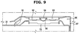
- FIG. 9 is an enlarged view showing a portion of FIG. 3
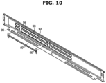
- FIG. 10 is a view illustrating a discharge cover of the cooking appliance according to the embodiment of the disclosure, which is viewed from the rear side.
- the discharge cover 90 may be disposed at a rear side on the upper portion of the main body 10.
- the discharge cover 90 may be disposed behind the cooking surface 31.
- the discharge cover 90 may be provided to correspond to the discharge port 72 in the upper side and lower side direction.
- the discharge port 72 may be disposed behind the cooking surface 31. Accordingly, the discharge cover 90 may be disposed behind the cooking surface 31 to correspond to the discharge port 72.
- the discharge cover 90 may be disposed to correspond to the cooking chamber discharge port 78 in the upper side and lower side direction.
- the discharge port 72 and the cooking chamber discharge port 78 may be disposed adjacent to each other, so that both of the discharge port 72 and the cooking chamber discharge port 78 are covered by a single discharge cover 90.
- the disclosure is not limited thereto, and when the discharge port 72 and the cooking chamber discharge port 78 are spaced apart from each other, the discharge cover 90 may be provided in a plurality of units thereof to cover the discharge port 72 and the cooking chamber discharge port 78.
- the discharge port 72 and the cooking chamber discharge port 78 may be disposed on the rear side of the cooking appliance 1 to prevent hot air from being discharged directly to the user who uses the cooking appliance 1.
- the discharge port 72, the cooking chamber discharge port 78, and the discharge cover 90 may be disposed on the rear side of the cooking surface 31.
- the discharge cover 90 may be provided to cover the discharge port 72 and the cooking chamber discharge port 78 to prevent a part of the user's body from being inserted into the discharge port 72 or the cooking chamber discharge port 78.
- the discharge cover 90 disposed adjacent to the discharge port 72.
- the discharge cover 90 further includes a configuration disposed adjacent to the cooking chamber discharge port 78, the configuration is the same as that disposed adjacent to the discharge port 72 described below, and thus descriptions thereof will be omitted.
- the discharge cover 90 includes a first through hole 92 provided so that air discharged from the discharge port 72 is discharged to the outside of the cooking appliance 1, a second through hole 93 disposed spaced apart from the first through hole 92, and an intermediate portion 94 disposed between the first through hole 92 and the second through hole 93.
- the discharge cover 90 may include an upper surface 91 formed to face upward of the cooking appliance 1.
- the first through hole 92, the second through hole 93, and the intermediate portion 94 may be formed as a region of the upper surface 91.
- the first and second through holes 92 and 93 may be formed to have an area smaller than or equal to the area of the discharge port 72.
- the area of the first and second through holes 92 and 93 may be provided smaller than the area of the discharge port 72, and the intermediate portion 94 disposed between the first and second through holes 92 and 93 may prevent a body part of a user from being inserted into the discharge port 72.
- the upper surface 91 of the discharge cover 90 may be disposed in parallel with the cooking surface 31. As the upper surface 91 of the discharge cover 90 is arranged in parallel with the cooking surface 31, the sense of unity of the upper exterior of the cooking appliance 1 is increased, so that the aesthetic feeling of the cooking appliance 1 may be increased.
- the color of the discharge cover 90 may be provided in a color substantially corresponding to the color of the cooking surface 31. Accordingly, the sense of unity of the cooking surface 31 and the discharge cover 90 may be further increased.
- the intermediate portion 94 formed as a region of the upper surface 91 may also be formed in parallel with the cooking surface 31.
- the discharge port 72 is provided so as to be opened toward the upper side of the cooking appliance 1, and air discharged from the discharge port 72 flows upward, and the intermediate portion 94, which is arranged in a direction approximately perpendicular to the upward direction of the cooking appliance 1, may hinder the flow of air discharged from the discharge port72
- the discharge cover 90 may include a discharge guide 95 disposed at a lower side of the intermediate portion 94 and guiding the air to the first and second through holes 92 and 93.
- the discharge guide 95 may be provided to protrude downward from the lower side of the intermediate portion 94.
- the discharge guide 95 may be provided to have a curved surface that is convexly formed in a lower side direction of the cooking appliance 1.
- the air flowing toward the lower surface of the intermediate portion 94 may collide with the discharge guide 95 to thereby be guided to the first and second through holes 92 and 93 along the curved surface of the discharge guide 95.
- the discharge guide 95 may be detachably coupled to the upper surface 91 of the discharge cover 90.
- the discharge cover 90 may be manufactured in a plate shape by a press method.
- the discharge cover 90 may be manufactured in a metal plate shape.
- the discharge guide 95 which is provided in a protruding shape having a curved surface, may not be manufactured by a press method, but when the discharge guide 95 is provided to be detachably coupled to the upper surface 91 of the discharge cover 90, the discharge cover 90 may be easily manufactured by a press method, and only the discharge guide 95 may be additionally manufactured and combined to the discharge cover 90, thereby enhancing the manufacturing efficiency of the discharge cover 90.
- the discharge cover 90 may include a rear surface 96 extending downward from the rear end of the upper surface 91.
- the rear surface 96 may be formed with an additional through hole 97 formed to allow air discharged from the discharge port 72 to additionally pass through the discharge cover 90.
- the additional through hole 97 may be provided to increase the flow efficiency of air that has failed to pass through the discharge cover 90 through the first and second through holes 92 and 93.
- the additional through hole 97 may be opened rearward of the cooking appliance 1. Accordingly, air may be prevented from being directly discharged to a user who uses the cooking appliance 1 in front of the cooking appliance 1.
- FIG. 11 is a view illustrating a state of the cooking appliance according to the embodiment of the disclosure before the cooking chamber is assembled
- FIG. 12 is a perspective view illustrating the cooking chamber of the cooking appliance according to the embodiment of the disclosure
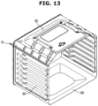
- FIG. 13 is a view illustrating an example of the cooking appliance according to the embodiment which shows coupling of some parts of the cooking chamber
- FIG. 14 is an enlarged view showing a portion of FIG. 13
- FIG. 15 is a view showing a cross section of FIG. 14 .
- the cooking chamber 20 of the cooking appliance 1 may be provided in an approximately rectangular parallelepiped shape having an opening with a large-capacity.
- the cooking chamber 20 may be formed of a metal material.
- the cooking chamber 20 is not easily manufactured in a unitary body.
- the cooking chamber 20 may be formed by manufacturing a plurality of components as shown in FIG. 11 , and welding the plurality of components to each other in a single unit as shown in FIG. 12 .
- the top plate 21, the bottom plate 22, the both side plates 23, the rear plate 24, and the front plate 25 of the cooking chamber 20 are individually manufactured and then welded to form an integral cooking chamber 20.
- the side plates 23 may be integrally manufactured with the bottom plate 22a, but the disclosure is not limited thereto, and the side plates 23 and the bottom plate 22 may be separately manufactured and welded to each other.
- the cooking chamber 20 may include a cooking chamber inside 20a having a front side that is open.
- the cooking chamber 20 may include an enamel coating 20b formed on a region forming the cooking chamber inside 20a.
- the enamel coating 20b may be formed in a region forming the cooking chamber inside 20a in the top plate 21, the bottom plate 22, the both side plates 23, and the rear plate 24 of the cooking chamber 20.
- the cooking chamber 20 is formed by welding the components 21, 22, 23, and 25 as described above, but when an external force is exerted on the cooking chamber 20, welded portions of the components 21, 22, 23, and 25 may be deformed due to weak stiffness.
- the cooking chamber 20 formed of a metal material is not damaged even when deformation occurs, but the enamel coating 20b coated on the cooking chamber inside 20a may be damaged.
- the external force when an external force is exerted on the cooking chamber 20, the external force is concentrated on a welded portion D at front ends of the top plate 21 and the both side plates 23, and a region of the enamel coating 20b coated on the welded portion D at the front ends of the top plate 21 and the both side plates 23 may be likely to be damaged.
- the cooking appliance 1 may include a reinforcing portion 21d provided to further secure the stiffness of the welded portion D at the front ends of the top plate 21 and the both side plates 23.
- the top plate 21 may include a top plate welding portion 21b disposed to overlap the both side plates 23 in the upper side and lower side direction to be welded to the both side plates 23.
- the both side plates 23 may include side plate welding portions 23b that are disposed to overlap the top plate 21 in the upper side and lower side direction so as to be welded to the top plate 21.
- the top plate welding portion 21b of the top plate 21 may be provided to extend further downward compared to the lower end of the top plate 21. Accordingly, the top plate welding portion 21b may be disposed to overlap the both side plates 23 in the upper side and lower side direction.
- the side plate welding portions 23b of the both side plates 23 may be disposed at positions corresponding to the top plate welding portion 21b in the upper side and lower side direction. Accordingly, the side plate welding portions 23b and the top plate welding portion 21b may be welded to each other to form a unitary body.
- the top plate 21 may include a top plate bent portion 21c that is formed by being bent to perpendicular to the forward direction.
- the top plate bent portion 21c may include a first bent (not shown) that is formed by being bent to be perpendicular to the top plate 21 that extends in the front side and rear side direction and a second bent 21c" that is formed by being bent from the first bent (not shown) to be perpendicular to the first bent (not shown) to extend in the front side and rear side direction.
- the top plate bent portion 21c may be provided in a shape including the first bent (not shown) bent at the front end of the top plate 21 and laterally extending outside the top plate 21 and then the second bent 21c" bent from the first bent (not shown) in the rear side direction.
- the both side plates 23 may include side plate bent portions 23c that are formed by being bent in a direction perpendicular to the forward direction.
- the side plate bent portion 23c includes a first bent 23c' that is formed by being bent to be perpendicular to the both side plates 23 that extends in the front side and rear side direction and a second bent 23c"formed by being bent from the first bent 23c' to be perpendicular to the front side and rear side direction.
- the side plate bent portion 23c may be provided in a shape including the first bent 23c' that is formed by being bent in the left side and right side direction from the front ends of the both side plates 23 and the second bent 23c"formed by being bent from the first bent 23c'in the rear side direction.
- the top plate bent portion 21c and the side plate bent portion 23c may be disposed in front of the top plate welding portion 21b and the side plate welding portion 23b, respectively.
- the top plate bent portion 21c and the side plate bent portion 23c may be provided so as not to overlap each other in the upper side and lower side direction.
- the top plate bent portion 21c may be provided to be disposed on the upper end of the side plate bent portion 23c.
- the top plate 21 and the both side plates 23 may be welded to each other a region behind the top plate bent portion 21c and the side plate bent portion 23c in the front side and rear side direction and a region around a middle portion between the top plate bent portion 21c and the side plate bent portion 23c in the upper side and lower side direction.
- the stiffness of the region behind the top plate bent portion 21c and the side plate bent portion 23c in the front side and rear side direction and the region around the middle portion between the top plate bent portion 21c and the side plate bent portion 23c in the upper side and lower side direction may be lower than that of other positions of the cooking chamber 20.
- the top plate 21 may include a reinforcing portion 21d that may additionally secure the stiffness of the region behind the top plate bent portion 21c and the side plate bent portion 23c in the front side and rear side direction and the region around the middle portion between the top plate bent portion 21c and the side plate bent portion 23c in the upper side and lower side direction.
- the reinforcing portion 21d may be provided to be welded to the both side plates 23 together with the top plate welding portion 21b.
- the reinforcing portion 21d may be provided to extend downward from the lower end of the top plate bent portion 21c.
- the reinforcing portion 21d may be disposed to come in contact with the side plate bent portion 23c disposed below the top plate bent portion 21c.
- the reinforcing portion 21d may extend downward by a length approximately corresponding to a length in which the top plate welding portion 21b extends downward.
- the reinforcing portion 21d may extend while having bents corresponding to the first bent (not shown) and the second bent 21c" of the top plate bent portion 21c. Accordingly, the reinforcing portion 21d may be provided to come in contact with the rear side of the side plate bent portion 23c as a whole.
- the reinforcing portion 21d may extend at a rear side a first portion 23c-1, which extends outward from the first bent 23c' of the side plate bent portion 23c in the left side and right side direction, so as to correspond to the first portion 23c-1.
- the reinforcing portion 21d may be bent at a rear side of the second bent 23c", which is bent at an end portion of the first portion 23c-1 of the side plate bent portion 23c, so as to correspond to the second bent 23c".
- the reinforcing portion 21d may extend at a lateral side of a second portion 23c-2, which extends rearward from the second bent 23c" of the side plate bent portion 23c, so as to correspond to the second portion 23c-2.
- the reinforcing portion 21d is disposed to come in contact with the side plate bent portion 23c as a whole, and the reinforcing portion 21d while in contact with the side plate bent portion 23c may be welded to the both side plates 23 together with the top plate welding portion 21b.
- the reinforcing portion 21d is additionally welded to the both side plates 23, the reinforcing portion 21d is caused to be welded at a region having a weak stiffness, that is, the region behind the top plate bent portion 21c and the side plate bent portion 23c in the front side and rear side direction and the region around the middle portion between the top plate bent portion 21c and the side plate bent portion 23c in the upper side and lower side direction, so that the stiffness of the weak region may be secured.
- the enamel coating coated on the region behind the top plate bent portion 21c and the side plate bent portion 23c in the front side and rear side direction and the region around the middle portion between the top plate bent portion 21c and the side plate bent portion 23c in the upper side and lower side direction may be prevented from being damaged.
Landscapes
- Engineering & Computer Science (AREA)
- Chemical & Material Sciences (AREA)
- Combustion & Propulsion (AREA)
- Mechanical Engineering (AREA)
- General Engineering & Computer Science (AREA)
- Baking, Grill, Roasting (AREA)
- Food Science & Technology (AREA)
- Electric Stoves And Ranges (AREA)
Claims (14)
- Appareil de cuisson comprenant :un corps principal (10) formant un compartiment machine (40) ;une chambre de cuisson (20) agencée sous le compartiment machine (40) ;un chemin d'écoulement intermédiaire (80) formé entre le compartiment machine (40) et la chambre de cuisson (20) par une plaque de séparation (100), le chemin d'écoulement intermédiaire (80) comprenant un premier orifice d'aspiration (80a) formé au niveau de l'extrémité avant de celui-ci à travers lequel l'air externe s'écoule dans le chemin d'écoulement intermédiaire (80), puis le long du chemin d'écoulement intermédiaire (80) dans un dispositif de soufflante (70) au niveau de l'extrémité arrière du chemin d'écoulement intermédiaire, le dispositif de soufflante (70) comprenant un ventilateur (71) configuré pour aspirer l'air dans le chemin d'écoulement intermédiaire (80) et un orifice d'évacuation (72) à l'arrière de l'appareil de cuisson à travers lequel l'air introduit par le ventilateur (71) est évacué à l'extérieur de l'appareil de cuisson ; etune partie d'ouverture (110) à travers laquelle l'air est introduit vers le chemin d'écoulement intermédiaire (80), la partie d'ouverture (110) comprenant une première partie d'ouverture (111) et une seconde partie d'ouverture (112) à travers lesquelles l'air est introduit vers le chemin d'écoulement intermédiaire (80),dans lequel la première partie d'ouverture (111) et la seconde partie d'ouverture (112) sont formées au niveau de la plaque de séparation (100),dans lequel la seconde partie d'ouverture (112) est agencée à une distance plus éloignée du ventilateur (71) que la première partie d'ouverture (111) et la seconde partie d'ouverture (112) comporte une aire plus grande qu'une aire de la première partie d'ouverture (111), etdans lequel l'air est introduit dans le compartiment machine (40) à travers un second orifice d'aspiration (55) pour s'écouler dans le chemin d'écoulement intermédiaire (80) à travers la première partie d'ouverture (111) et la seconde partie d'ouverture (112).
- Appareil de cuisson selon la revendication 1, dans lequel la plaque de séparation (100) est configurée pour diviser le compartiment machine (40) à partir du chemin d'écoulement intermédiaire (80) dans une direction du côté supérieur et du côté inférieur du corps principal (10).
- Appareil de cuisson selon la revendication 2, dans lequel la plaque de séparation (100) comporte une surface supérieure qui forme une partie inférieure du compartiment machine (40) et comporte une surface inférieure qui forme une partie supérieure du chemin d'écoulement intermédiaire (80).
- Appareil de cuisson selon la revendication 1, dans lequel une section d'écoulement d'air dans le chemin d'écoulement intermédiaire (80) est prévue pour augmenter et diminuer dans une seconde direction (B) perpendiculaire à une première direction (A) le long de laquelle le premier orifice d'aspiration (80a) est formé, et
la seconde partie d'ouverture (112) est formée sur une région (82) dans laquelle la section d'écoulement d'air dans le chemin d'écoulement intermédiaire (80) diminue le long de la première direction (A). - Appareil de cuisson selon la revendication 4, dans lequel la première partie d'ouverture (111) est formée sur une région (81) dans laquelle la section d'écoulement d'air dans le chemin d'écoulement intermédiaire (80) est constante le long de la première direction (A).
- Appareil de cuisson selon la revendication 5, dans lequel le ventilateur (71) est agencé sur la région (81) dans laquelle la section d'écoulement d'air dans le chemin d'écoulement intermédiaire (80) est constante le long de la première direction (A).
- Appareil de cuisson selon la revendication 1, dans lequel le chemin d'écoulement intermédiaire (80) est formé le long d'une première région (81) et d'une seconde région (82) séparées l'une de l'autre dans une seconde direction (B) perpendiculaire à une première direction (A) dans laquelle le premier orifice d'aspiration (80a) est formé,une section d'écoulement d'air dans la première région (81) est prévue pour être plus grande qu'une section d'écoulement d'air dans la seconde région (82), etle ventilateur (71) est agencé sur la première région (81).
- Appareil de cuisson selon la revendication 7, dans lequel la première partie d'ouverture (111) est agencée sur la première région, et la seconde partie d'ouverture (112) est agencée sur la seconde région (82).
- Appareil de cuisson selon la revendication 7, dans lequel la première région (81) et la seconde région (82) sont divisées par rapport à un centre (X) du chemin d'écoulement intermédiaire, et
un angle d'inclinaison d'une paroi latérale de la première région (83) formant la première région (81) par rapport à la première direction (A) est inférieur à un angle d'inclinaison d'une paroi latérale de la seconde région (84) formant la seconde région (82) par rapport à la première direction (A). - Appareil de cuisson selon la revendication 1, dans lequel le premier orifice d'aspiration (80a) comporte une section d'aspiration plus grande qu'une section d'aspiration du second orifice d'aspiration (55).
- Appareil de cuisson selon la revendication 1, comprenant en outre une partie de cuisson côté supérieur (30) agencée au-dessus du compartiment machine (40),dans lequel la partie de cuisson côté supérieur (30) comprend une surface de cuisson (31) sur laquelle un objet de cuisson doit être placé et un dispositif de chauffe (33) agencé dans le compartiment machine (40), etla première partie d'ouverture (111) et la seconde partie d'ouverture (112) sont agencées de telle sorte que la chaleur générée à partir du dispositif de chauffe (33) soit fournie pour s'écouler hors du compartiment machine (40) conjointement à l'air aspiré à travers le second orifice d'aspiration (55).
- Appareil de cuisson selon la revendication 11, dans lequel l'orifice d'évacuation (72) est ouvert vers le haut pour évacuer l'air déplacé par le ventilateur (71) ; et dans lequel l'appareil de cuisson comprend en outre un capot d'évacuation (90) qui couvre l'orifice d'évacuation (72), le capot d'évacuation (90) comprenant une surface supérieure (91) agencée parallèlement à la surface de cuisson (31).
- Appareil de cuisson selon la revendication 12, dans lequel le capot d'évacuation (90) comprend :un premier trou traversant (92) et un second trou traversant (93) que l'air évacué de l'orifice d'évacuation (72) traverse dans une direction ascendante ;une partie intermédiaire (94) formée entre le premier trou traversant (92) et le second trou traversant (93) ; etun guide d'évacuation (95) agencé en dessous de la partie intermédiaire (94) pour guider l'air vers le premier trou traversant (92) et le second trou traversant (93).
- Appareil de cuisson selon la revendication 12, dans lequel le capot d'évacuation (90) comprend :une surface arrière (96) qui s'étend vers le bas à partir d'une extrémité arrière de la surface supérieure (91) de l'orifice d'évacuation (72) ; etun trou traversant supplémentaire (97) agencé dans la surface arrière (96) et formé pour permettre à l'air évacué de l'orifice d'évacuation (72) de le traverser.
Applications Claiming Priority (2)
| Application Number | Priority Date | Filing Date | Title |
|---|---|---|---|
| KR1020200039453A KR102809921B1 (ko) | 2020-03-31 | 2020-03-31 | 조리기기 |
| PCT/KR2021/003979 WO2021201587A1 (fr) | 2020-03-31 | 2021-03-31 | Appareil de cuisson |
Publications (4)
| Publication Number | Publication Date |
|---|---|
| EP4063741A1 EP4063741A1 (fr) | 2022-09-28 |
| EP4063741A4 EP4063741A4 (fr) | 2022-12-28 |
| EP4063741C0 EP4063741C0 (fr) | 2025-03-12 |
| EP4063741B1 true EP4063741B1 (fr) | 2025-03-12 |
Family
ID=77855655
Family Applications (1)
| Application Number | Title | Priority Date | Filing Date |
|---|---|---|---|
| EP21781535.6A Active EP4063741B1 (fr) | 2020-03-31 | 2021-03-31 | Appareil de cuisson |
Country Status (4)
| Country | Link |
|---|---|
| US (2) | US11512857B2 (fr) |
| EP (1) | EP4063741B1 (fr) |
| KR (1) | KR102809921B1 (fr) |
| WO (1) | WO2021201587A1 (fr) |
Families Citing this family (3)
| Publication number | Priority date | Publication date | Assignee | Title |
|---|---|---|---|---|
| KR102436401B1 (ko) * | 2022-01-25 | 2022-08-25 | 삼주이엔지 주식회사 | 해상 선박용 주방 인덕션 레인지 |
| US20250052428A1 (en) * | 2023-08-07 | 2025-02-13 | Haier Us Appliance Solutions, Inc. | Cooling system assembly for a cooking appliance |
| WO2025146912A1 (fr) * | 2024-01-04 | 2025-07-10 | 삼성전자주식회사 | Appareil de cuisson |
Family Cites Families (22)
| Publication number | Priority date | Publication date | Assignee | Title |
|---|---|---|---|---|
| US2526890A (en) * | 1946-01-12 | 1950-10-24 | Cribben And Sexton Company | Circulating air passage structure for ranges |
| US3832988A (en) * | 1974-01-02 | 1974-09-03 | Whirlpool Co | Oven vent for smooth top range |
| FR2726633B1 (fr) * | 1994-11-04 | 1996-11-29 | Europ Equip Menager | Procede de refroidissement de la porte d'un appareil de cuisson et appareil de cuisson mettant en oeuvre le procede |
| DE29602780U1 (de) * | 1996-02-16 | 1997-06-19 | AEG Hausgeräte GmbH, 90429 Nürnberg | Haushaltsherd |
| KR200152112Y1 (ko) | 1996-07-11 | 1999-07-15 | 윤종용 | 오븐렌지의 도어 냉각장치 |
| KR100204892B1 (ko) | 1996-08-27 | 1999-06-15 | 정몽규 | 냉각장치 |
| KR0133001Y1 (ko) | 1996-09-16 | 1998-12-15 | 김광호 | 가스오븐렌지의 냉각팬제어장치 |
| USD468159S1 (en) | 2002-02-14 | 2003-01-07 | Maytag Corporation | Oven vent cover for a cooking appliance |
| USD468961S1 (en) | 2002-02-14 | 2003-01-21 | Maytag Corporation | Oven vent cover for a gas cooking appliance |
| DE102007005718A1 (de) * | 2007-02-05 | 2008-08-07 | BSH Bosch und Siemens Hausgeräte GmbH | Lüftungsblende und Ofen |
| KR20090104943A (ko) * | 2008-04-01 | 2009-10-07 | 엘지전자 주식회사 | 전기오븐 |
| KR101531060B1 (ko) | 2009-04-30 | 2015-06-23 | 엘지전자 주식회사 | 공기 순환 수단을 포함한 오븐 레인지 |
| US20150241069A1 (en) * | 2014-02-27 | 2015-08-27 | Electrolux Home Products, Inc. | Wall oven cooling system |
| US10288298B2 (en) * | 2014-03-12 | 2019-05-14 | Bsh Home Appliances Corporation | Home cooking appliance having a low-profile rear vent trim |
| US9513015B2 (en) * | 2014-06-19 | 2016-12-06 | Dacor | Oven with control panel cooling system |
| KR101654725B1 (ko) * | 2015-01-16 | 2016-09-06 | 엘지전자 주식회사 | 조리기기 |
| EP3249304B1 (fr) | 2016-05-25 | 2021-11-03 | Electrolux Appliances Aktiebolag | Four de cuisson avec un système de refroidissement |
| KR102210370B1 (ko) * | 2016-06-03 | 2021-02-01 | 삼성전자주식회사 | 오븐 |
| WO2018044067A1 (fr) * | 2016-09-01 | 2018-03-08 | Samsung Electronics Co., Ltd. | Four |
| EP3327358B1 (fr) | 2016-11-25 | 2022-03-23 | Electrolux Appliances Aktiebolag | Cavité ayant un revêtement d'émail, appareil de cuisson comprenant une telle cavité et procédé de fabrication d'une telle cavité |
| US10495318B2 (en) | 2017-05-26 | 2019-12-03 | Electrolux Home Products, Inc. | Balanced cooling duct for cooking oven |
| KR102153615B1 (ko) * | 2018-07-23 | 2020-09-21 | 엘지전자 주식회사 | 조리기기 |
-
2020
- 2020-03-31 KR KR1020200039453A patent/KR102809921B1/ko active Active
-
2021
- 2021-03-30 US US17/216,875 patent/US11512857B2/en active Active
- 2021-03-31 EP EP21781535.6A patent/EP4063741B1/fr active Active
- 2021-03-31 WO PCT/KR2021/003979 patent/WO2021201587A1/fr not_active Ceased
-
2022
- 2022-11-16 US US17/988,320 patent/US12000596B2/en active Active
Also Published As
| Publication number | Publication date |
|---|---|
| EP4063741A4 (fr) | 2022-12-28 |
| EP4063741C0 (fr) | 2025-03-12 |
| EP4063741A1 (fr) | 2022-09-28 |
| US12000596B2 (en) | 2024-06-04 |
| US20230069901A1 (en) | 2023-03-09 |
| KR102809921B1 (ko) | 2025-05-22 |
| KR20210121955A (ko) | 2021-10-08 |
| WO2021201587A1 (fr) | 2021-10-07 |
| US11512857B2 (en) | 2022-11-29 |
| US20210302028A1 (en) | 2021-09-30 |
Similar Documents
| Publication | Publication Date | Title |
|---|---|---|
| US12000596B2 (en) | Cooking appliance | |
| JP5242911B2 (ja) | 調理機器 | |
| EP1731843B1 (fr) | Four | |
| CN101322613B (zh) | 具有分隔器的烹调设备 | |
| JP3933621B2 (ja) | 壁掛け型電子レンジ | |
| EP3745030B1 (fr) | Appareil de cuisson | |
| US7629561B2 (en) | Electric oven with hood having opening/closing device to open and close an exhaust passage | |
| US6864472B2 (en) | Exhaust and ventilation system for mountable type microwave oven | |
| EP1586821B1 (fr) | Installation de refroidissement pour un appareil de cuisson | |
| EP1586820B1 (fr) | Dispositif de refroidissement d'un appareil de cuisson | |
| KR20180080062A (ko) | 조리기기 | |
| CA2454010C (fr) | Systeme de ventilation d'appareil de cuisson | |
| US7671310B2 (en) | Microwave range having hood | |
| US6818874B2 (en) | Wall-mounted type microwave oven | |
| JP3977383B2 (ja) | 電子レンジ | |
| US20110006056A1 (en) | Microwave oven | |
| US7271373B2 (en) | Microwave oven | |
| KR102850856B1 (ko) | 후드 겸용 전자 레인지 | |
| KR102799413B1 (ko) | 조리기기 | |
| US6750434B1 (en) | Microwave oven | |
| JP2000039153A (ja) | 加熱調理器 | |
| KR101224246B1 (ko) | 오븐 | |
| KR20240084499A (ko) | 조리기기 | |
| KR20040061355A (ko) | 후드겸용 전자레인지 | |
| KR20040061380A (ko) | 후드겸용 전자레인지 |
Legal Events
| Date | Code | Title | Description |
|---|---|---|---|
| STAA | Information on the status of an ep patent application or granted ep patent |
Free format text: STATUS: THE INTERNATIONAL PUBLICATION HAS BEEN MADE |
|
| PUAI | Public reference made under article 153(3) epc to a published international application that has entered the european phase |
Free format text: ORIGINAL CODE: 0009012 |
|
| STAA | Information on the status of an ep patent application or granted ep patent |
Free format text: STATUS: REQUEST FOR EXAMINATION WAS MADE |
|
| 17P | Request for examination filed |
Effective date: 20220622 |
|
| AK | Designated contracting states |
Kind code of ref document: A1 Designated state(s): AL AT BE BG CH CY CZ DE DK EE ES FI FR GB GR HR HU IE IS IT LI LT LU LV MC MK MT NL NO PL PT RO RS SE SI SK SM TR |
|
| A4 | Supplementary search report drawn up and despatched |
Effective date: 20221125 |
|
| RIC1 | Information provided on ipc code assigned before grant |
Ipc: F24C 15/32 20060101ALN20221121BHEP Ipc: F24C 15/08 20060101ALI20221121BHEP Ipc: F24C 15/00 20060101AFI20221121BHEP |
|
| DAV | Request for validation of the european patent (deleted) | ||
| DAX | Request for extension of the european patent (deleted) | ||
| STAA | Information on the status of an ep patent application or granted ep patent |
Free format text: STATUS: EXAMINATION IS IN PROGRESS |
|
| 17Q | First examination report despatched |
Effective date: 20240403 |
|
| GRAP | Despatch of communication of intention to grant a patent |
Free format text: ORIGINAL CODE: EPIDOSNIGR1 |
|
| RIC1 | Information provided on ipc code assigned before grant |
Ipc: F24C 15/32 20060101ALN20240902BHEP Ipc: F24C 15/08 20060101ALI20240902BHEP Ipc: F24C 15/00 20060101AFI20240902BHEP |
|
| STAA | Information on the status of an ep patent application or granted ep patent |
Free format text: STATUS: GRANT OF PATENT IS INTENDED |
|
| INTG | Intention to grant announced |
Effective date: 20241010 |
|
| GRAS | Grant fee paid |
Free format text: ORIGINAL CODE: EPIDOSNIGR3 |
|
| GRAA | (expected) grant |
Free format text: ORIGINAL CODE: 0009210 |
|
| STAA | Information on the status of an ep patent application or granted ep patent |
Free format text: STATUS: THE PATENT HAS BEEN GRANTED |
|
| AK | Designated contracting states |
Kind code of ref document: B1 Designated state(s): AL AT BE BG CH CY CZ DE DK EE ES FI FR GB GR HR HU IE IS IT LI LT LU LV MC MK MT NL NO PL PT RO RS SE SI SK SM TR |
|
| REG | Reference to a national code |
Ref country code: GB Ref legal event code: FG4D |
|
| REG | Reference to a national code |
Ref country code: CH Ref legal event code: EP |
|
| REG | Reference to a national code |
Ref country code: DE Ref legal event code: R096 Ref document number: 602021027574 Country of ref document: DE |
|
| REG | Reference to a national code |
Ref country code: IE Ref legal event code: FG4D |
|
| U01 | Request for unitary effect filed |
Effective date: 20250331 |
|
| U07 | Unitary effect registered |
Designated state(s): AT BE BG DE DK EE FI FR IT LT LU LV MT NL PT RO SE SI Effective date: 20250404 |
|
| U20 | Renewal fee for the european patent with unitary effect paid |
Year of fee payment: 5 Effective date: 20250410 |
|
| PG25 | Lapsed in a contracting state [announced via postgrant information from national office to epo] |
Ref country code: RS Free format text: LAPSE BECAUSE OF FAILURE TO SUBMIT A TRANSLATION OF THE DESCRIPTION OR TO PAY THE FEE WITHIN THE PRESCRIBED TIME-LIMIT Effective date: 20250612 |
|
| PG25 | Lapsed in a contracting state [announced via postgrant information from national office to epo] |
Ref country code: ES Free format text: LAPSE BECAUSE OF FAILURE TO SUBMIT A TRANSLATION OF THE DESCRIPTION OR TO PAY THE FEE WITHIN THE PRESCRIBED TIME-LIMIT Effective date: 20250312 |
|
| PG25 | Lapsed in a contracting state [announced via postgrant information from national office to epo] |
Ref country code: NO Free format text: LAPSE BECAUSE OF FAILURE TO SUBMIT A TRANSLATION OF THE DESCRIPTION OR TO PAY THE FEE WITHIN THE PRESCRIBED TIME-LIMIT Effective date: 20250612 |
|
| PG25 | Lapsed in a contracting state [announced via postgrant information from national office to epo] |
Ref country code: HR Free format text: LAPSE BECAUSE OF FAILURE TO SUBMIT A TRANSLATION OF THE DESCRIPTION OR TO PAY THE FEE WITHIN THE PRESCRIBED TIME-LIMIT Effective date: 20250312 |
|
| PG25 | Lapsed in a contracting state [announced via postgrant information from national office to epo] |
Ref country code: GR Free format text: LAPSE BECAUSE OF FAILURE TO SUBMIT A TRANSLATION OF THE DESCRIPTION OR TO PAY THE FEE WITHIN THE PRESCRIBED TIME-LIMIT Effective date: 20250613 |
|
| PG25 | Lapsed in a contracting state [announced via postgrant information from national office to epo] |
Ref country code: SM Free format text: LAPSE BECAUSE OF FAILURE TO SUBMIT A TRANSLATION OF THE DESCRIPTION OR TO PAY THE FEE WITHIN THE PRESCRIBED TIME-LIMIT Effective date: 20250312 |
|
| PG25 | Lapsed in a contracting state [announced via postgrant information from national office to epo] |
Ref country code: PL Free format text: LAPSE BECAUSE OF FAILURE TO SUBMIT A TRANSLATION OF THE DESCRIPTION OR TO PAY THE FEE WITHIN THE PRESCRIBED TIME-LIMIT Effective date: 20250312 |
|
| PG25 | Lapsed in a contracting state [announced via postgrant information from national office to epo] |
Ref country code: CZ Free format text: LAPSE BECAUSE OF FAILURE TO SUBMIT A TRANSLATION OF THE DESCRIPTION OR TO PAY THE FEE WITHIN THE PRESCRIBED TIME-LIMIT Effective date: 20250312 |
|
| REG | Reference to a national code |
Ref country code: CH Ref legal event code: H13 Free format text: ST27 STATUS EVENT CODE: U-0-0-H10-H13 (AS PROVIDED BY THE NATIONAL OFFICE) Effective date: 20251023 |
|
| PG25 | Lapsed in a contracting state [announced via postgrant information from national office to epo] |
Ref country code: SK Free format text: LAPSE BECAUSE OF FAILURE TO SUBMIT A TRANSLATION OF THE DESCRIPTION OR TO PAY THE FEE WITHIN THE PRESCRIBED TIME-LIMIT Effective date: 20250312 |
|
| PG25 | Lapsed in a contracting state [announced via postgrant information from national office to epo] |
Ref country code: IS Free format text: LAPSE BECAUSE OF FAILURE TO SUBMIT A TRANSLATION OF THE DESCRIPTION OR TO PAY THE FEE WITHIN THE PRESCRIBED TIME-LIMIT Effective date: 20250712 |
|
| PG25 | Lapsed in a contracting state [announced via postgrant information from national office to epo] |
Ref country code: MC Free format text: LAPSE BECAUSE OF FAILURE TO SUBMIT A TRANSLATION OF THE DESCRIPTION OR TO PAY THE FEE WITHIN THE PRESCRIBED TIME-LIMIT Effective date: 20250312 |
|
| PLBE | No opposition filed within time limit |
Free format text: ORIGINAL CODE: 0009261 |
|
| STAA | Information on the status of an ep patent application or granted ep patent |
Free format text: STATUS: NO OPPOSITION FILED WITHIN TIME LIMIT |
|
| PG25 | Lapsed in a contracting state [announced via postgrant information from national office to epo] |
Ref country code: CH Free format text: LAPSE BECAUSE OF NON-PAYMENT OF DUE FEES Effective date: 20250331 |
|
| PG25 | Lapsed in a contracting state [announced via postgrant information from national office to epo] |
Ref country code: IE Free format text: LAPSE BECAUSE OF NON-PAYMENT OF DUE FEES Effective date: 20250331 |
|
| REG | Reference to a national code |
Ref country code: CH Ref legal event code: L10 Free format text: ST27 STATUS EVENT CODE: U-0-0-L10-L00 (AS PROVIDED BY THE NATIONAL OFFICE) Effective date: 20260121 |
|
| 26N | No opposition filed |
Effective date: 20251215 |
|
| PGFP | Annual fee paid to national office [announced via postgrant information from national office to epo] |
Ref country code: GB Payment date: 20260224 Year of fee payment: 6 |
|
| U20 | Renewal fee for the european patent with unitary effect paid |
Year of fee payment: 6 Effective date: 20260323 |