EP4063877A1 - Verfahren zur steuerung eines elektrotechnischen geräts - Google Patents
Verfahren zur steuerung eines elektrotechnischen geräts Download PDFInfo
- Publication number
- EP4063877A1 EP4063877A1 EP22157495.7A EP22157495A EP4063877A1 EP 4063877 A1 EP4063877 A1 EP 4063877A1 EP 22157495 A EP22157495 A EP 22157495A EP 4063877 A1 EP4063877 A1 EP 4063877A1
- Authority
- EP
- European Patent Office
- Prior art keywords
- phase
- electrotechnical
- alert
- phases
- determined
- Prior art date
- Legal status (The legal status is an assumption and is not a legal conclusion. Google has not performed a legal analysis and makes no representation as to the accuracy of the status listed.)
- Pending
Links
Images



Classifications
-
- G—PHYSICS
- G01—MEASURING; TESTING
- G01R—MEASURING ELECTRIC VARIABLES; MEASURING MAGNETIC VARIABLES
- G01R31/00—Arrangements for testing electric properties; Arrangements for locating electric faults; Arrangements for electrical testing characterised by what is being tested not provided for elsewhere
- G01R31/50—Testing of electric apparatus, lines, cables or components for short-circuits, continuity, leakage current or incorrect line connections
- G01R31/58—Testing of lines, cables or conductors
-
- G—PHYSICS
- G01—MEASURING; TESTING
- G01R—MEASURING ELECTRIC VARIABLES; MEASURING MAGNETIC VARIABLES
- G01R19/00—Arrangements for measuring currents or voltages or for indicating presence or sign thereof
- G01R19/003—Measuring mean values of current or voltage during a given time interval
-
- G—PHYSICS
- G01—MEASURING; TESTING
- G01R—MEASURING ELECTRIC VARIABLES; MEASURING MAGNETIC VARIABLES
- G01R19/00—Arrangements for measuring currents or voltages or for indicating presence or sign thereof
- G01R19/0092—Measuring current only
-
- G—PHYSICS
- G01—MEASURING; TESTING
- G01K—MEASURING TEMPERATURE; MEASURING QUANTITY OF HEAT; THERMALLY-SENSITIVE ELEMENTS NOT OTHERWISE PROVIDED FOR
- G01K13/00—Thermometers specially adapted for specific purposes
-
- G—PHYSICS
- G01—MEASURING; TESTING
- G01K—MEASURING TEMPERATURE; MEASURING QUANTITY OF HEAT; THERMALLY-SENSITIVE ELEMENTS NOT OTHERWISE PROVIDED FOR
- G01K7/00—Measuring temperature based on the use of electric or magnetic elements directly sensitive to heat ; Power supply therefor, e.g. using thermoelectric elements
-
- G—PHYSICS
- G01—MEASURING; TESTING
- G01K—MEASURING TEMPERATURE; MEASURING QUANTITY OF HEAT; THERMALLY-SENSITIVE ELEMENTS NOT OTHERWISE PROVIDED FOR
- G01K7/00—Measuring temperature based on the use of electric or magnetic elements directly sensitive to heat ; Power supply therefor, e.g. using thermoelectric elements
- G01K7/02—Measuring temperature based on the use of electric or magnetic elements directly sensitive to heat ; Power supply therefor, e.g. using thermoelectric elements using thermoelectric elements, e.g. thermocouples
-
- G—PHYSICS
- G01—MEASURING; TESTING
- G01R—MEASURING ELECTRIC VARIABLES; MEASURING MAGNETIC VARIABLES
- G01R31/00—Arrangements for testing electric properties; Arrangements for locating electric faults; Arrangements for electrical testing characterised by what is being tested not provided for elsewhere
- G01R31/08—Locating faults in cables, transmission lines, or networks
-
- G—PHYSICS
- G01—MEASURING; TESTING
- G01R—MEASURING ELECTRIC VARIABLES; MEASURING MAGNETIC VARIABLES
- G01R31/00—Arrangements for testing electric properties; Arrangements for locating electric faults; Arrangements for electrical testing characterised by what is being tested not provided for elsewhere
- G01R31/50—Testing of electric apparatus, lines, cables or components for short-circuits, continuity, leakage current or incorrect line connections
- G01R31/56—Testing of electric apparatus
-
- G—PHYSICS
- G01—MEASURING; TESTING
- G01R—MEASURING ELECTRIC VARIABLES; MEASURING MAGNETIC VARIABLES
- G01R31/00—Arrangements for testing electric properties; Arrangements for locating electric faults; Arrangements for electrical testing characterised by what is being tested not provided for elsewhere
- G01R31/50—Testing of electric apparatus, lines, cables or components for short-circuits, continuity, leakage current or incorrect line connections
- G01R31/66—Testing of connections, e.g. of plugs or non-disconnectable joints
-
- H—ELECTRICITY
- H02—GENERATION; CONVERSION OR DISTRIBUTION OF ELECTRIC POWER
- H02H—EMERGENCY PROTECTIVE CIRCUIT ARRANGEMENTS
- H02H5/00—Emergency protective circuit arrangements for automatic disconnection directly responsive to an undesired change from normal non-electric working conditions with or without subsequent reconnection
- H02H5/04—Emergency protective circuit arrangements for automatic disconnection directly responsive to an undesired change from normal non-electric working conditions with or without subsequent reconnection responsive to abnormal temperature
- H02H5/041—Emergency protective circuit arrangements for automatic disconnection directly responsive to an undesired change from normal non-electric working conditions with or without subsequent reconnection responsive to abnormal temperature additionally responsive to excess current
Definitions
- the invention belongs to the field of electrotechnical apparatus.
- the invention improves this situation.
- the method according to the invention by comparing the specific parameters over a given time interval, makes it possible to alert on the causes of future dangers for the electrotechnical apparatus, the electrical network and the user. In particular, these dangers can be prevented before they occur by appropriate action.
- the method makes it possible, for example, to reduce the risks of fire starting due to a poor connection between the network and the electrotechnical device.
- the intensity values are effective intensity values and the specific parameters correspond to the temperature values divided by the squares of the effective intensity values measured at the corresponding instants of the determined time interval.
- the specific parameters use temperature and the square of the current rms values so that the specific parameters are an image, or physical equivalent, of the internal resistances of each phase. This makes it possible in particular to determine connection faults.
- the comparison comprises the determination of a regression function of the specific parameters for each of the phases over the determined time interval and the comparison of the regression functions.
- the regression function makes it possible to compare the behaviors of each of the phases over the determined time interval to identify differences between each of the phases.
- the comparison of the regression functions comprises the comparison of respective leading coefficients, the functions being linear functions.
- the comparison of the respective leading coefficients makes it possible to determine the differences in evolution of the specific parameters between each of the phases over the determined time interval.
- an alert is determined based on the comparison when a difference between a first leading coefficient of a regression function associated with a first phase and a second leading coefficient of a regression function associated with a second phase is greater at a determined alert coefficient threshold. This makes it possible to determine an alert when the difference in evolution of the specific parameters between two phases over the determined time interval is greater than a threshold value.
- a sum of the squares of the residuals is determined for each of the phases from their respective linear regression function.
- the sum of the squares of the residuals of the linear regression functions makes it possible in particular to determine whether a difference in values between the guiding coefficients of each of the linear regression functions is due to random variations of the specific parameters.
- the regression function of a phase is determined by a method of least squares. This method makes it possible to determine a regression function minimizing the deviations between the specific parameters of the determined time interval and their value estimated by the regression function.
- the determined alert includes a notification indicating a possible connection fault between the electrotechnical device and the electrical network or within the electrotechnical device itself. This makes it possible, for example, to warn the user or an external service responsible for maintenance of a potential connection fault between the electrotechnical device and the electrical network.
- the alert includes an identifier of a phase on which a possible connection fault has appeared. This makes it possible to target a phase subject to a potential connection fault.
- the alert comprises an alert message sent to a server, the alert message comprising an identifier of the electrotechnical device and at least one of an identifier of a phase of the electrotechnical device and a duration operation of the electrical device.
- a maintenance service to remotely assess the reality of a problem with the electrotechnical device or to warn a security service of a company using the device in order to preserve the safety of these employees and their equipment.
- This also makes it possible to ensure traceability of the alerts, which may in particular be used by insurance companies in the event of a fault in the electrotechnical device.
- This also allows the manufacturer, the user or even the maintenance operator of electrotechnical devices to obtain statistical data according to the types of electrotechnical devices and the alerts received.
- the manufacturer of electrotechnical devices using the treatment process of alert messages according to the invention will for example be capable of identifying a faulty production line or a component of a type of fragile electrotechnical device.
- the user of electrotechnical devices implementing the message processing method he will be able, for example, to guarantee the safety of his teams and his equipment or even to identify recurring problems on certain types of devices, which will in particular make it possible to enlighten your choices in the future acquisition of other electrotechnical devices.
- the maintenance operator using the message processing method can, for example, associate maintenance actions with the various fault functions of a type of electrotechnical device.
- each alert message is also associated with a phase of the identified electrotechnical device and in which the method comprises a step of identifying a manufacturing defect or of connecting a phase of a type of device from alert messages. This makes it possible to identify a manufacturing or connection defect of a phase of a type of device.
- the invention also relates to an electrotechnical system comprising an electrotechnical device comprising three phases respectively connected to three phases of an electrical network, the electrotechnical system also comprising at least three temperature sensors suitable for measuring a temperature on each of the phases, the electrotechnical system further comprising a computer suitable for controlling the electrotechnical system so as to implement any one of the control methods presented by the present disclosure.
- the electrotechnical system advantageously comprises at least three intensity measurement means suitable for measuring an intensity on each of the phases.
- the invention further relates to a data processing device comprising a computer configured to implement one of the methods for processing alert messages described by this document.
- the invention finally relates to a computer program product comprising instructions for the implementation of any of the above methods when implemented by a computer.
- FIG 2 An example of an electrical engineering system is shown in figure 2 .
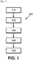
- This example of an electrotechnical system allows in particular the implementation of a example of a method 100 for controlling an electrotechnical device presented in figure 1 .
- the electrical engineering system 1 comprises an electrical engineering device 2.
- Electrical engineering is characterized by a set of techniques relating to the practical applications of electrical, magnetic and electromagnetic phenomena. Consequently, an electrotechnical device within the meaning of the invention can be a device putting into practice an electric, magnetic or electromagnetic phenomenon.
- An electrotechnical device can for example correspond to a breaking device such as a circuit breaker, a contactor or a switch.
- An electrotechnical device can also correspond to a transformer, an alternator motor or even a machine tool.
- the electrotechnical device 2 is connected to an electrical network, for example to a three-phase electrical network 3 as illustrated in the figure 2 .
- the electrotechnical device 2 comprises three phases, each being connected to a respective phase of the three-phase electrical network 3.
- the electrotechnical system 1 comprises at least three temperature sensors 4 suitable for measuring temperature values T on each of the phases.
- the temperature sensors can for example be arranged inside the electrotechnical device 2 as shown in the figure 1 or outside this electrical device.
- a temperature sensor according to the invention can for example be a thermocouple sensor or a temperature probe.
- the electrotechnical system 1 comprises current measuring means (not shown) making it possible to measure current values I on each of the phases.
- the current measuring means can for example correspond to ammeters arranged on each of the phases.
- these intensity measurement means are suitable for measuring or estimating effective intensity values I rms of the current (also known by the terminology “root mean square current” or “RMS current” in English) on each of the phases .
- the electrotechnical system 1 can also comprise a computer PROC suitable for executing code instructions, the latter being able for example to be included in a memory MEM.
- the computer PROC is therefore connected to the memory MEM so that it can use the information contained in the memory MEM.
- the memory MEM can for example comprise code instructions for the execution of one of the methods presented by the present application so that the computer PROC can execute them.
- the computer PROC can for example comprise a processor, a controller or a microcontroller. It can for example be included in the electrotechnical device 2 as illustrated by the figure 1 .
- the memory MEM may for example comprise a ROM (Read-Only Memory) memory, a RAM (Random Access Memory) memory, an EEPROM (Electrically Erasable Programmable Read-Only Memory) memory or any other type of suitable storage means allowing the reading of code instructions.
- the memory MEM can for example comprise optical, electronic or even magnetic storage means.
- the computer PROC is also suitable for receiving data from the temperature sensors 4 and the intensity measurement means corresponding to temperature and intensity values on each of the phases. These temperature and intensity values can for example be stored in the memory MEM and/or sent to a server SERV.
- the example method 100 for controlling an electrotechnical device can comprise a measurement, for each phase, of a plurality of temperature values T in a determined time interval. These measurements are taken by the temperature sensors, for example following a command sent by the computer PROC. Each temperature value is advantageously associated with a time at which it was measured over the determined time interval.
- method 100 may include measuring, for each phase, a plurality of intensity values I in the determined time interval. These measurements are carried out by means of intensity measurement, for example following a command sent by the computer.
- the measurements of intensity values can correspond to effective intensity values of the electric current in each phase.
- Each intensity value is advantageously associated with a time at which it was measured over the determined time interval.
- the temperature and intensity values are for example stored in the memory MEM and/or on a server SERV. They can for example be sent to the server SERV by telecommunications channels such as 3G, 4G, wired, optical, electromagnetic channels, etc.
- the method can be implemented in real time so that, in examples, the determined time interval can be a sliding time interval between the different executions of the method.
- the time interval can be substantially the same between different executions of the method.
- a size of the time interval can be changed between different executions of the method.
- the time interval may comprise a number of specific parameters P which may or may not vary between different executions of the method.
- the time interval can for example be greater than five minutes but it can also be shorter. It can for example be of the order of one or more tens of minutes.
- the time interval is for example between 2 minutes and 180 minutes.
- Temperature values and intensity values are for example measured at least every two minutes for each phase and advantageously several times per minute. A longer measurement rate of the temperature and intensity values is also envisaged. A rate of measurement of an intensity value and a temperature value can for example be between one minute and twenty minutes for each of the phases.
- the memory and/or the server therefore comprises measurements representing a change in the intensity I and the temperature T in each phase over the determined time interval.
- method 100 may comprise a determination, for each phase, of a plurality of specific parameters P.
- Each specific parameter P is determined from a temperature value T and a value of intensity I of the corresponding phase measured at corresponding instants of the determined time interval.
- the plurality of specific parameters can for example comprise at least thirty specific parameters, each of the phases being able for example to be associated with ten specific parameters.
- the plurality of specific parameters can for example comprise between 24 and 300 specific parameters and is advantageously greater than 6 specific parameters.
- the determined time interval corresponds to approximately twenty minutes.
- the energy Q dissipated in the form of heat between two instants is estimated by the temperature value T measured at a given instant of the time interval on a phase by the sensor temperature, the intensity i being estimated by the effective intensity I rms so that the specific parameter P is homologous to an internal resistance of the phase.
- FIG. 4 A figure illustrating a representation of the specific parameters P obtained on the three phases in this variant is represented in figure 4 .
- the abscissa axis represents the time t and the ordinate axis represents the values of the specific parameters P.
- the first phase is referenced ph1
- the second phase is referenced ph2
- the third phase is referenced ph3.
- the method 100 may include comparing some or all of the specific parameters of the plurality of phase-specific parameters over the determined time interval.
- the comparison of the specific parameters of the phases over the determined time interval can comprise an identification of a different behavior, that is to say of a different evolution, of the specific parameters P between two phases or of a phase by relative to the other two over the determined time interval.
- a different behavior that is to say of a different evolution
- the specific parameters P between two phases or of a phase by relative to the other two over the determined time interval.
- method 100 may include determining an alert based on the comparison of some or all of the specific parameters of the plurality of phase-specific parameters over the determined time interval.
- the identification of a different behavior of the specific parameters P of two phases or of one phase compared to the two others by the comparison of the specific parameters P can comprise the determination of a regression function of the specific parameters P for each of the phases over a specified time interval.
- the behaviors of the phases are compared in pairs, i.e. the behavior of the first phase is compared with the second phase or the behavior of the second phase compared to the third phase or even the behavior of the third phase compared to the first phase.
- the method makes it possible to determine an alert when it observes that two phases evolve differently over the determined time interval. Furthermore, by comparing all the pairs of phases, the method is capable of identifying a faulty phase as being the phase whose evolution diverges from the other two over the determined time interval. In this case, the method also makes it possible to identify the origin of the failure.
- the regression function of the specific parameters P of a phase makes it possible to mathematically model the evolution of the specific parameters P of this phase over the time interval considered and therefore to be able to compare the phases with each other.
- the regression functions modeling the evolution of the specific parameters P of each phase can be linear regression functions (hereinafter called first linear regression functions to differentiate them from the second linear regression functions which will be introduced in a variant of achievement).
- the first linear regression functions of the specific parameters P of each phase can thus be determined by a method of least squares.
- the method of least squares intends to minimize the sum of the squares of the residuals.
- the residual can correspond to the vertical deviation (along the ordinate axis in the Figure 4 ) between a specific parameter P obtained from a temperature measurement and an intensity measurement at a given instant and its value estimated at the same instant by the first linear regression function.
- the identification of different behaviors of the specific parameters P between two phases or of one phase with respect to the two others can comprise the comparison of the respective leading coefficients.
- the comparison of the leading coefficients (ie of the slopes) of the first linear regression functions represents a comparison of the evolution of the parameters P over time over the determined time interval.
- an alert is determined (block 150) on the basis of the comparison of all or part of the specific parameters P when an absolute value of a difference between a first leading coefficient of a first linear regression function associated with a first phase and a second leading coefficient of a first linear regression function associated with a second phase is greater than a determined alert coefficient threshold.
- the alert coefficient threshold can for example correspond to a percentage difference between the leading coefficients. The differences between the alert coefficients must be understood in absolute value here.
- the alert coefficient threshold is less than 10% and preferably less than 5%.
- the alert coefficient threshold can be chosen according to the number of specific parameters P determined in the time interval for each phase. The higher the number of specific parameters, the closer the alert coefficient threshold can be to 0%.
- the method will compare the residuals obtained from the first linear regression functions of these two phases to residuals obtained from second linear regression functions, which are in particular obtained from the first linear regression functions of these two phases.
- the second linear regression functions can in particular be obtained from the guiding coefficients of the first linear regression functions.
- a first sum SCEE ph of the squares of the residuals (the acronym SCEE meaning Sum of the Squares of the Estimated Deviations, the estimated deviations being the residuals), the residuals corresponding to the vertical deviations between the specific parameters P associated with a phase and their value estimated by the first linear regression function associated with this phase.
- SCEE Sum of the Squares of the Estimated Deviations, the estimated deviations being the residuals
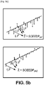
- the first sum SCEE ph1 of the squares of the residuals of the first phase is equal to the sum of the vertical deviations between the specific parameters P of the first phase and their value estimated by the first function of linear regression at the corresponding instants as represented on the figure 5a .
- the first SEEA ph sums of the squares of the residuals have already been calculated (since these first SEEA ph sums have been minimized to find the first linear regression functions).
- a first total sum SCEET of the squares of the residuals (the acronym SCEET meaning Total Sum of Squares of Estimated Differences) is thus calculated, which corresponds to an addition of the first sums SCEE ph of the squares of the residuals of the two compared phases.
- the first total sum SCEET of the squares of the residuals therefore corresponds in the example illustrated in figure 5a to the addition of the first SCEE sum ph1 of the squares of the residuals of the first phase and the first sum SEEA ph2 of the squares of the residuals of the second phase.
- An average directing coefficient CD m of the two compared phases is also calculated from their respective first linear regression functions.
- the average leading coefficient CD m corresponds to the sum of the respective leading coefficient of the first regression functions of the two compared phases, divided by two.
- At least one second linear regression function is then determined for each compared phase on the basis of the specific parameters P associated with this phase and of the mean leading coefficient of the two compared phases.
- each of the leading coefficients of the second determined linear regression functions is equal to the average leading coefficient CD m of the first linear regression functions of the two compared phases. Only a parameter corresponding to the ordinate at the origin of the second linear regression functions is different between the second linear regression functions.
- the second linear regression functions are therefore all parallel with an average slope coefficient and their parameter corresponding to the ordinate at the origin is determined from the specific parameters P of their phase.
- a second SCEEDP sum of the squares of the residuals (the acronym SCEEDP meaning Sum of the Squares of the Estimated Deviations of the Parallel Lines), the residuals corresponding to the vertical deviations between the specific parameters P associated to the phase of the second linear regression function and their value estimated by this second linear regression function.
- a second sum SCEEDP of the squares of the residuals of a second linear regression function of a phase therefore corresponds to the sum of the squares of the vertical deviations between the specific parameters P of the phase and their value estimated by the second linear regression function.
- a second total sum SCEEDP ph of the squares of the residues associated with a phase can be determined corresponding to the sum of the squares of the residues of the second linear regression functions associated with the phase.
- This determination is represented in figure 5b where the second total sum SCEEDP ph1 of the squares of the residuals associated with the first phase is illustrated at the top while the second total sum of the SCEEDP ph2 of the squares of the residuals associated with the second phase is illustrated at the bottom.
- a residual error of variation of the leading coefficients Erv is determined corresponding to the difference (SCEEDPT - SCEET) between the second total sum of the squares of the residuals (SCEEDPT) and the first total sum (SCEET) of the squares of the residuals.
- the evolutions of the compared phases are considered to be different, in which case an alert (block 150) is determined.
- the variation threshold can for example be less than 10% and advantageously less than 6% when F is expressed as a percentage. It is for example equal to 5% or 1%.
- the method is therefore capable of identifying a phase which is not functioning correctly.
- the method is able to identify that there is a problem with the operation of the electrotechnical system but it cannot identify on which phases the problem is located.
- the method is capable of determining that there is an operating problem.
- a determined alert may include a notification indicating a possible connection fault between the electrotechnical device and the electrical network.
- the specific parameters P being dependent on the temperature and the intensity of the phase, they are linked to the internal resistance of the phases which differ between the phases in particular due to connection faults between the electrotechnical device and the electrical network.
- the alert can also include an audible or visual signal, for example intended for users close to the electrotechnical system to warn them of a potential fault.
- a determined alert can also include an identifier of a phase on which a possible connection fault has appeared. As explained above, when the method is able to determine which phase differs from the other two, the determined alert can also include an identifier of this phase. This will in particular facilitate the maintenance of the electrotechnical system.
- the method for controlling an electrotechnical device according to the invention therefore makes it possible to reduce the risks, both human and material, associated with the use of an electrotechnical device connected to an electrical network.
- it makes it possible to prevent fire outbreaks linked to a fault in the connection of the phases of the electrotechnical device and of the electrical network by detecting this fault upstream of the fire.
- the determined alert can also comprise an alert message sent to a server SERV.
- the alert message may include at least one of an identifier of a phase of the electrotechnical device and an operating time of the electrotechnical device. The alert message can therefore be sent to a manufacturer, a security service, a maintenance operator, etc.
- the present disclosure also presents a data processing device 10 suitable for processing alert messages.
- This device 10 is shown in picture 3 .
- the device 10 can therefore comprise a server SERV adapted to receive alert messages.
- Each alert message is associated with an electrotechnical device by an identifier and an operating time.
- Alert messages can also include a phase of the identified electrotechnical device.
- the alert messages received by the server can therefore identify a plurality of electrotechnical devices 2 belonging to a plurality of electrotechnical systems 1.
- These alert messages can be stored in a memory MEM2 of the processing device 10.
- the memory MEM2 can include the same information storage means as the memory MEM presented with reference to the figure 2 .
- the server SERV can also be adapted to receive temperature values and current values associated with electrotechnical devices. These values can also be stored by the memory MEM2. In which case, the process presented with reference to the figure 1 can be controlled at the level of the server SERV, for example by a processor PROC2 similar to the processor PROC and connected to the memory MEM2.
- the processor PROC2 is also suitable for executing code instructions for controlling a method for processing alert messages from the server SERV.
- the method of processing alert messages may include identifying a type of device including a manufacturing defect from the alert messages. For example, a type of electrotechnical device comprising a manufacturing defect is identified when a number of error messages for this type of device exceeds a predetermined manufacturing defect threshold.
- the processor is able to identify a type of electrotechnical device which regularly presents alert messages.
- a type of electrotechnical device can for example correspond to or include a model of electrotechnical devices, a brand of electrotechnical devices or even a production line of electrotechnical devices.
- the method for processing alert messages can also comprise a determination of a fault function of a type of electrotechnical device from the alert messages.
- a fault function can for example be a statistical function for the appearance of alerts of a type of electrotechnical device as a function of its number of hours of operation.
- the statistical function for the appearance of alerts can also include a fault at the level of a phase when the alert messages include a phase identifier.
- the method for processing alert messages can also include identification of a manufacturing or connection defect of a phase of a type of device.
- the method can identify a manufacturing or connection defect of a phase of a type of device.
- a manufacturing or connection defect of a phase of a type of device can be identified when a number of alert messages identifying the same phase of the same type of device is greater than a determined phase fault threshold.
- the implementation of the method for processing alert messages according to the invention therefore allows statistical processing of alert messages.
- it allows an interested person to identify faults in the manufacture or connection of types of electrotechnical devices and, more precisely, of certain phases of electrotechnical devices. It also makes it possible to construct fault functions of types of electrotechnical devices over time and in particular as a function of a number of hours of operation.
Landscapes
- Physics & Mathematics (AREA)
- General Physics & Mathematics (AREA)
- Engineering & Computer Science (AREA)
- Power Engineering (AREA)
- Testing Of Devices, Machine Parts, Or Other Structures Thereof (AREA)
- Testing Of Short-Circuits, Discontinuities, Leakage, Or Incorrect Line Connections (AREA)
- Testing Electric Properties And Detecting Electric Faults (AREA)
- Remote Monitoring And Control Of Power-Distribution Networks (AREA)
Applications Claiming Priority (1)
| Application Number | Priority Date | Filing Date | Title |
|---|---|---|---|
| FR2103011A FR3121229A1 (fr) | 2021-03-25 | 2021-03-25 | Procédé de contrôle d’un appareil électrotechnique |
Publications (1)
| Publication Number | Publication Date |
|---|---|
| EP4063877A1 true EP4063877A1 (de) | 2022-09-28 |
Family
ID=76034768
Family Applications (1)
| Application Number | Title | Priority Date | Filing Date |
|---|---|---|---|
| EP22157495.7A Pending EP4063877A1 (de) | 2021-03-25 | 2022-02-18 | Verfahren zur steuerung eines elektrotechnischen geräts |
Country Status (4)
| Country | Link |
|---|---|
| US (1) | US12228593B2 (de) |
| EP (1) | EP4063877A1 (de) |
| CN (1) | CN115201543A (de) |
| FR (1) | FR3121229A1 (de) |
Citations (3)
| Publication number | Priority date | Publication date | Assignee | Title |
|---|---|---|---|---|
| US20110050141A1 (en) * | 2009-08-31 | 2011-03-03 | Gm Global Technology Operations, Inc. | Electric motor stator winding temperature estimation |
| US20170146586A1 (en) * | 2014-07-07 | 2017-05-25 | El-Watch As | Damage Preventing Identification System for Conductors and Coupling Points in Electrical Systems With Data Acquisition |
| US20180011133A1 (en) * | 2013-11-06 | 2018-01-11 | General Electric Company | Temperature compensation of insulation monitoring for rotating machines |
Family Cites Families (5)
| Publication number | Priority date | Publication date | Assignee | Title |
|---|---|---|---|---|
| US5510687A (en) * | 1994-04-29 | 1996-04-23 | Allen-Bradley Company, Inc. | Electric motor controller with temperature protection |
| US10761147B2 (en) * | 2016-11-21 | 2020-09-01 | GRID20/20, Inc. | Transformer monitoring and data analysis systems and methods |
| US9852837B2 (en) * | 2014-01-28 | 2017-12-26 | General Electric Company | Multi-winding high sensitivity current transformer |
| US10784677B2 (en) * | 2018-01-29 | 2020-09-22 | S&C Electric Company | Enhanced utility disturbance monitor |
| US11221353B2 (en) * | 2018-07-06 | 2022-01-11 | Schneider Electric USA, Inc. | Systems and methods for analyzing power quality events in an electrical system |
-
2021
- 2021-03-25 FR FR2103011A patent/FR3121229A1/fr not_active Ceased
-
2022
- 2022-02-18 EP EP22157495.7A patent/EP4063877A1/de active Pending
- 2022-03-10 US US17/691,585 patent/US12228593B2/en active Active
- 2022-03-23 CN CN202210304794.5A patent/CN115201543A/zh active Pending
Patent Citations (3)
| Publication number | Priority date | Publication date | Assignee | Title |
|---|---|---|---|---|
| US20110050141A1 (en) * | 2009-08-31 | 2011-03-03 | Gm Global Technology Operations, Inc. | Electric motor stator winding temperature estimation |
| US20180011133A1 (en) * | 2013-11-06 | 2018-01-11 | General Electric Company | Temperature compensation of insulation monitoring for rotating machines |
| US20170146586A1 (en) * | 2014-07-07 | 2017-05-25 | El-Watch As | Damage Preventing Identification System for Conductors and Coupling Points in Electrical Systems With Data Acquisition |
Also Published As
| Publication number | Publication date |
|---|---|
| US20220308097A1 (en) | 2022-09-29 |
| US12228593B2 (en) | 2025-02-18 |
| FR3121229A1 (fr) | 2022-09-30 |
| CN115201543A (zh) | 2022-10-18 |
Similar Documents
| Publication | Publication Date | Title |
|---|---|---|
| EP3485284B1 (de) | Erkennung von anomalien in einem elektrischen netz | |
| EP2169799B1 (de) | Bestimmung der Richtung eines Erdschluss-Fehlers | |
| WO2008128324A1 (fr) | Localisation de défaut sur un réseau électrique par mesures de tension distribuées | |
| CA2888716A1 (fr) | Systeme de surveillance d'un ensemble de composants d'un equipement | |
| FR2963960A1 (fr) | Surveillance des particules dans un systeme de lubrification | |
| FR3104710A1 (fr) | Méthodes et systèmes de surveillance d’installations électriques | |
| EP4226169B1 (de) | Verfahren und vorrichtung zur überwachung des betriebszustandes von schutzschaltern | |
| EP3729302B1 (de) | Verfahren und system zur unterstützung der fehlersuche eines komplexes systems | |
| EP0537066B1 (de) | Verfahren zur selektiven Detektion von Widerstandsdefekten in Stromverteilungsnetzwerken | |
| EP3232212B1 (de) | System und verfahren zur detektion eines lichtbogens | |
| EP1845383B1 (de) | Verfahren zur Erkennung der Sättigung eines Stromtransformators | |
| EP3298549A1 (de) | Verfahren und system zur vorhersage der durchführung eines vorgegebenen zustands eines objekts | |
| EP4063877A1 (de) | Verfahren zur steuerung eines elektrotechnischen geräts | |
| FR2966928A1 (fr) | Procede et dispositif de surveillance d'une chaine de mesure redondee | |
| EP4300113B1 (de) | Detektion von neutral- oder phasenverlust | |
| EP2910958A1 (de) | Störungserkennung, insbesondere einer vorübergehenden Störung, in einem Stromnetz | |
| EP3552033A1 (de) | Installation zur diagnose einer elektrischen maschine | |
| EP2820731B1 (de) | Verfahren und anordnung zum überwachen eines gasisolierten schottraums | |
| EP3650876A1 (de) | Detektion einer elektrischen störung in einem generator | |
| EP3748373A1 (de) | Diagnose für verteilungsnetzwerk | |
| FR2969845A1 (fr) | Dispositif et procede de protection terre restreinte | |
| FR3075951A1 (fr) | Detection de contact intermittent sur capteur moteur | |
| FR3161283A1 (fr) | détermination d’un risque d’apparition d’arcs électrique dans un circuit électrique d’un système aéronautique | |
| FR3140958A1 (fr) | Procédé de détection d’anomalie dans une série temporelle observée de valeurs d’une grandeur physique représentative des performances d’un système. | |
| EP0494012A1 (de) | Verfahren und Vorrichtung für die Überprüfung des elektrischen Isolierungszustands einer elektrisch leitenden Konstruktion |
Legal Events
| Date | Code | Title | Description |
|---|---|---|---|
| PUAI | Public reference made under article 153(3) epc to a published international application that has entered the european phase |
Free format text: ORIGINAL CODE: 0009012 |
|
| STAA | Information on the status of an ep patent application or granted ep patent |
Free format text: STATUS: THE APPLICATION HAS BEEN PUBLISHED |
|
| AK | Designated contracting states |
Kind code of ref document: A1 Designated state(s): AL AT BE BG CH CY CZ DE DK EE ES FI FR GB GR HR HU IE IS IT LI LT LU LV MC MK MT NL NO PL PT RO RS SE SI SK SM TR |
|
| STAA | Information on the status of an ep patent application or granted ep patent |
Free format text: STATUS: REQUEST FOR EXAMINATION WAS MADE |
|
| 17P | Request for examination filed |
Effective date: 20230327 |
|
| RBV | Designated contracting states (corrected) |
Designated state(s): AL AT BE BG CH CY CZ DE DK EE ES FI FR GB GR HR HU IE IS IT LI LT LU LV MC MK MT NL NO PL PT RO RS SE SI SK SM TR |
|
| STAA | Information on the status of an ep patent application or granted ep patent |
Free format text: STATUS: EXAMINATION IS IN PROGRESS |
|
| 17Q | First examination report despatched |
Effective date: 20240828 |