EP4063894A1 - Mehrstrahl aesa-multifunktionssystem - Google Patents
Mehrstrahl aesa-multifunktionssystem Download PDFInfo
- Publication number
- EP4063894A1 EP4063894A1 EP22163311.8A EP22163311A EP4063894A1 EP 4063894 A1 EP4063894 A1 EP 4063894A1 EP 22163311 A EP22163311 A EP 22163311A EP 4063894 A1 EP4063894 A1 EP 4063894A1
- Authority
- EP
- European Patent Office
- Prior art keywords
- radar
- command
- function
- aperture
- aperture beam
- Prior art date
- Legal status (The legal status is an assumption and is not a legal conclusion. Google has not performed a legal analysis and makes no representation as to the accuracy of the status listed.)
- Pending
Links
Images





Classifications
-
- G—PHYSICS
- G01—MEASURING; TESTING
- G01S—RADIO DIRECTION-FINDING; RADIO NAVIGATION; DETERMINING DISTANCE OR VELOCITY BY USE OF RADIO WAVES; LOCATING OR PRESENCE-DETECTING BY USE OF THE REFLECTION OR RERADIATION OF RADIO WAVES; ANALOGOUS ARRANGEMENTS USING OTHER WAVES
- G01S7/00—Details of systems according to groups G01S13/00, G01S15/00, G01S17/00
- G01S7/02—Details of systems according to groups G01S13/00, G01S15/00, G01S17/00 of systems according to group G01S13/00
- G01S7/41—Details of systems according to groups G01S13/00, G01S15/00, G01S17/00 of systems according to group G01S13/00 using analysis of echo signal for target characterisation; Target signature; Target cross-section
- G01S7/414—Discriminating targets with respect to background clutter
-
- G—PHYSICS
- G01—MEASURING; TESTING
- G01S—RADIO DIRECTION-FINDING; RADIO NAVIGATION; DETERMINING DISTANCE OR VELOCITY BY USE OF RADIO WAVES; LOCATING OR PRESENCE-DETECTING BY USE OF THE REFLECTION OR RERADIATION OF RADIO WAVES; ANALOGOUS ARRANGEMENTS USING OTHER WAVES
- G01S7/00—Details of systems according to groups G01S13/00, G01S15/00, G01S17/00
- G01S7/02—Details of systems according to groups G01S13/00, G01S15/00, G01S17/00 of systems according to group G01S13/00
- G01S7/023—Interference mitigation, e.g. reducing or avoiding non-intentional interference with other HF-transmitters, base station transmitters for mobile communication or other radar systems, e.g. using electro-magnetic interference [EMI] reduction techniques
-
- G—PHYSICS
- G01—MEASURING; TESTING
- G01S—RADIO DIRECTION-FINDING; RADIO NAVIGATION; DETERMINING DISTANCE OR VELOCITY BY USE OF RADIO WAVES; LOCATING OR PRESENCE-DETECTING BY USE OF THE REFLECTION OR RERADIATION OF RADIO WAVES; ANALOGOUS ARRANGEMENTS USING OTHER WAVES
- G01S13/00—Systems using the reflection or reradiation of radio waves, e.g. radar systems; Analogous systems using reflection or reradiation of waves whose nature or wavelength is irrelevant or unspecified
- G01S13/02—Systems using reflection of radio waves, e.g. primary radar systems; Analogous systems
- G01S13/06—Systems determining position data of a target
- G01S13/42—Simultaneous measurement of distance and other co-ordinates
- G01S13/426—Scanning radar, e.g. 3D radar
-
- G—PHYSICS
- G01—MEASURING; TESTING
- G01S—RADIO DIRECTION-FINDING; RADIO NAVIGATION; DETERMINING DISTANCE OR VELOCITY BY USE OF RADIO WAVES; LOCATING OR PRESENCE-DETECTING BY USE OF THE REFLECTION OR RERADIATION OF RADIO WAVES; ANALOGOUS ARRANGEMENTS USING OTHER WAVES
- G01S13/00—Systems using the reflection or reradiation of radio waves, e.g. radar systems; Analogous systems using reflection or reradiation of waves whose nature or wavelength is irrelevant or unspecified
- G01S13/88—Radar or analogous systems specially adapted for specific applications
- G01S13/93—Radar or analogous systems specially adapted for specific applications for anti-collision purposes
- G01S13/933—Radar or analogous systems specially adapted for specific applications for anti-collision purposes of aircraft or spacecraft
-
- G—PHYSICS
- G01—MEASURING; TESTING
- G01S—RADIO DIRECTION-FINDING; RADIO NAVIGATION; DETERMINING DISTANCE OR VELOCITY BY USE OF RADIO WAVES; LOCATING OR PRESENCE-DETECTING BY USE OF THE REFLECTION OR RERADIATION OF RADIO WAVES; ANALOGOUS ARRANGEMENTS USING OTHER WAVES
- G01S13/00—Systems using the reflection or reradiation of radio waves, e.g. radar systems; Analogous systems using reflection or reradiation of waves whose nature or wavelength is irrelevant or unspecified
- G01S13/88—Radar or analogous systems specially adapted for specific applications
- G01S13/95—Radar or analogous systems specially adapted for specific applications for meteorological use
- G01S13/953—Radar or analogous systems specially adapted for specific applications for meteorological use mounted on aircraft
-
- G—PHYSICS
- G01—MEASURING; TESTING
- G01S—RADIO DIRECTION-FINDING; RADIO NAVIGATION; DETERMINING DISTANCE OR VELOCITY BY USE OF RADIO WAVES; LOCATING OR PRESENCE-DETECTING BY USE OF THE REFLECTION OR RERADIATION OF RADIO WAVES; ANALOGOUS ARRANGEMENTS USING OTHER WAVES
- G01S7/00—Details of systems according to groups G01S13/00, G01S15/00, G01S17/00
- G01S7/02—Details of systems according to groups G01S13/00, G01S15/00, G01S17/00 of systems according to group G01S13/00
- G01S7/03—Details of HF subsystems specially adapted therefor, e.g. common to transmitter and receiver
-
- H—ELECTRICITY
- H01—ELECTRIC ELEMENTS
- H01Q—ANTENNAS, i.e. RADIO AERIALS
- H01Q1/00—Details of, or arrangements associated with, antennas
- H01Q1/27—Adaptation for use in or on movable bodies
- H01Q1/28—Adaptation for use in or on aircraft, missiles, satellites, or balloons
-
- H—ELECTRICITY
- H01—ELECTRIC ELEMENTS
- H01Q—ANTENNAS, i.e. RADIO AERIALS
- H01Q1/00—Details of, or arrangements associated with, antennas
- H01Q1/27—Adaptation for use in or on movable bodies
- H01Q1/28—Adaptation for use in or on aircraft, missiles, satellites, or balloons
- H01Q1/281—Nose antennas
-
- H—ELECTRICITY
- H01—ELECTRIC ELEMENTS
- H01Q—ANTENNAS, i.e. RADIO AERIALS
- H01Q21/00—Antenna arrays or systems
- H01Q21/06—Arrays of individually energised antenna units similarly polarised and spaced apart
- H01Q21/061—Two dimensional planar arrays
-
- H—ELECTRICITY
- H01—ELECTRIC ELEMENTS
- H01Q—ANTENNAS, i.e. RADIO AERIALS
- H01Q25/00—Antennas or antenna systems providing at least two radiating patterns
-
- H—ELECTRICITY
- H01—ELECTRIC ELEMENTS
- H01Q—ANTENNAS, i.e. RADIO AERIALS
- H01Q25/00—Antennas or antenna systems providing at least two radiating patterns
- H01Q25/02—Antennas or antenna systems providing at least two radiating patterns providing sum and difference patterns
-
- H—ELECTRICITY
- H01—ELECTRIC ELEMENTS
- H01Q—ANTENNAS, i.e. RADIO AERIALS
- H01Q3/00—Arrangements for changing or varying the orientation or the shape of the directional pattern of the waves radiated from an antenna or antenna system
- H01Q3/26—Arrangements for changing or varying the orientation or the shape of the directional pattern of the waves radiated from an antenna or antenna system varying the relative phase or relative amplitude of energisation between two or more active radiating elements; varying the distribution of energy across a radiating aperture
- H01Q3/30—Arrangements for changing or varying the orientation or the shape of the directional pattern of the waves radiated from an antenna or antenna system varying the relative phase or relative amplitude of energisation between two or more active radiating elements; varying the distribution of energy across a radiating aperture varying the relative phase between the radiating elements of an array
- H01Q3/34—Arrangements for changing or varying the orientation or the shape of the directional pattern of the waves radiated from an antenna or antenna system varying the relative phase or relative amplitude of energisation between two or more active radiating elements; varying the distribution of energy across a radiating aperture varying the relative phase between the radiating elements of an array by electrical means
- H01Q3/36—Arrangements for changing or varying the orientation or the shape of the directional pattern of the waves radiated from an antenna or antenna system varying the relative phase or relative amplitude of energisation between two or more active radiating elements; varying the distribution of energy across a radiating aperture varying the relative phase between the radiating elements of an array by electrical means with variable phase-shifters
- H01Q3/38—Arrangements for changing or varying the orientation or the shape of the directional pattern of the waves radiated from an antenna or antenna system varying the relative phase or relative amplitude of energisation between two or more active radiating elements; varying the distribution of energy across a radiating aperture varying the relative phase between the radiating elements of an array by electrical means with variable phase-shifters the phase-shifters being digital
- H01Q3/385—Scan control logics
-
- G—PHYSICS
- G01—MEASURING; TESTING
- G01S—RADIO DIRECTION-FINDING; RADIO NAVIGATION; DETERMINING DISTANCE OR VELOCITY BY USE OF RADIO WAVES; LOCATING OR PRESENCE-DETECTING BY USE OF THE REFLECTION OR RERADIATION OF RADIO WAVES; ANALOGOUS ARRANGEMENTS USING OTHER WAVES
- G01S13/00—Systems using the reflection or reradiation of radio waves, e.g. radar systems; Analogous systems using reflection or reradiation of waves whose nature or wavelength is irrelevant or unspecified
- G01S13/02—Systems using reflection of radio waves, e.g. primary radar systems; Analogous systems
- G01S2013/0236—Special technical features
- G01S2013/0245—Radar with phased array antenna
- G01S2013/0254—Active array antenna
-
- G—PHYSICS
- G01—MEASURING; TESTING
- G01S—RADIO DIRECTION-FINDING; RADIO NAVIGATION; DETERMINING DISTANCE OR VELOCITY BY USE OF RADIO WAVES; LOCATING OR PRESENCE-DETECTING BY USE OF THE REFLECTION OR RERADIATION OF RADIO WAVES; ANALOGOUS ARRANGEMENTS USING OTHER WAVES
- G01S13/00—Systems using the reflection or reradiation of radio waves, e.g. radar systems; Analogous systems using reflection or reradiation of waves whose nature or wavelength is irrelevant or unspecified
- G01S13/02—Systems using reflection of radio waves, e.g. primary radar systems; Analogous systems
- G01S2013/0236—Special technical features
- G01S2013/0272—Multifunction radar
-
- Y—GENERAL TAGGING OF NEW TECHNOLOGICAL DEVELOPMENTS; GENERAL TAGGING OF CROSS-SECTIONAL TECHNOLOGIES SPANNING OVER SEVERAL SECTIONS OF THE IPC; TECHNICAL SUBJECTS COVERED BY FORMER USPC CROSS-REFERENCE ART COLLECTIONS [XRACs] AND DIGESTS
- Y02—TECHNOLOGIES OR APPLICATIONS FOR MITIGATION OR ADAPTATION AGAINST CLIMATE CHANGE
- Y02A—TECHNOLOGIES FOR ADAPTATION TO CLIMATE CHANGE
- Y02A90/00—Technologies having an indirect contribution to adaptation to climate change
- Y02A90/10—Information and communication technologies [ICT] supporting adaptation to climate change, e.g. for weather forecasting or climate simulation
Definitions
- GCS Robust Ground Clutter Suppression
- WxR Airborne Weather Radar
- PRF Low Pulse Repetition Frequency
- GCS Global System for Mobile Communications
- PWS Predictive Wind Shear
- SWGA electromechanically scanned slotted waveguide arrays
- Sophisticated multi-mode military airborne radars feature multiple-Pulse Repetition Frequency (PRF) and modulated waveforms to overcome these GCS challenges.
- PRF Pulse Repetition Frequency
- modulated waveforms to overcome these GCS challenges.
- PRF Pulse Repetition Frequency
- radar hardware architectures are prohibitively costly for a commercial operator.
- Sophisticated GCS techniques such as Space Time Adaptive Processing (STAAP) are routinely used within the military community, but are too computationally intensive requiring sophisticated hardware that are counter SWAP-C for the commercial operator.
- Additional electromechanically scanned GCS system may offer a 2-beam pattern (Azimuth / Elevation) or a 4-beam pattern which require a nontrivial time interval to raster scan, or "azimuthally pause and elevation jump" to acquire the radar returns of the 2-beam position/4-beam position radar returns.
- inventions of the inventive concepts disclosed herein are directed to a multi-beam multi-function radar antenna system.
- the system may comprise a single active electronically scanned array (AESA) mounted at a fixed boresight onboard an aircraft, the single AESA configured for a segmented aperture enabling a first aperture beam having a first aperture beam characteristic, a first azimuth, and a first elevation, the segmented aperture also enabling one or more second aperture beams having a second aperture beam characteristic, a second azimuth, and a second elevation, each of the first aperture beam and the second aperture beam or beams being independently steered, coherent, and simultaneously radiated from the single AESA.
- AESA electronically scanned array
- the system may also include one or more aircraft systems onboard the aircraft configured to 1) receive a specific radar dataset from the single AESA and 2) perform a system function based on the received specific radar dataset, the specific radar dataset provided by one of the first aperture beam and the second aperture beam.
- the system may include a controller operatively coupled with the single AESA and the aircraft system and a tangible, non-transitory memory configured to communicate with the controller, the tangible, non-transitory memory having instructions stored therein that, in response to execution by the controller, cause the controller to carry out each function of the system.
- the system may receive a first radar command from a first system of the aircraft system and a second radar command from a second system of the aircraft system, the first radar command includes the first aperture beam characteristic, the first azimuth, the first elevation, the second radar command includes the second aperture beam characteristic, the second azimuth, and the second elevation.
- the system may segment the single AESA into at least two AESA subarrays, based on the first radar command and the second radar command, to transmit and receive the first aperture beam and the second aperture beam, the first aperture beam having the first aperture beam characteristic based on the first radar command and the second aperture beam having the second aperture beam characteristic based on the second radar command and transmit and steer the first aperture beam based on the first radar command and the second aperture beam based on the second radar command.
- the system may receive a first radar return from the first aperture beam and a second radar return from the second aperture beam and digitally combine the first radar return from the first aperture beam and the second radar return from the second aperture beam via a digital signal processing to create a first specific radar dataset associated with the first system and a second specific radar dataset associated with the second system.
- the system may also supply the first system with the first specific radar dataset associated with the first system and the second system with the second specific radar dataset associated with the second system and execute the system function of the first system based on the first specific radar dataset associated with the first system and the system function of the second system based on the second specific radar dataset associated with the second system.
- a further embodiment of the inventive concepts disclosed herein is directed to a method for simultaneous multi-beam multi-function radar antenna operation.
- the method may include receiving a first radar command from a first system onboard an aircraft, the first system associated with a single active electronically scanned array (AESA) mounted at a fixed boresight onboard the aircraft, the first radar command includes a first aperture beam characteristic, a first azimuth, and a first elevation associated with a first aperture beam.
- AESA electronically scanned array
- the method may also include receiving a second radar command from a second system onboard the aircraft, the second radar command associated with the single AESA and includes a second aperture beam characteristic, a second azimuth, and a second elevation associated with a second aperture beam.
- the method may further include receiving an aircraft state data from an aircraft state data sensor and determining a hierarchy of radar function based on the aircraft state data. Then, in response to the first radar command and the second radar command, the method may include segmenting the single AESA into at least two subarrays based on the hierarchy of radar function, to transmit and receive the first aperture beam and the second aperture beam, the first aperture beam having the first aperture beam characteristic based on the first radar command and the second aperture beam having the second aperture beam characteristic based on the second radar command.
- the method may also include transmitting and steering the first aperture beam based on the first radar command and the second aperture beam based on the second radar command and receiving a first radar return from the first aperture beam and a second radar return from the second aperture beam.
- the method may then include digitally combining the first radar return and the second radar return via a digital signal processing and creating a first specific radar dataset associated with the first system and a second specific radar dataset associated with the second system.
- the method may further include supplying the first system with the first specific radar dataset associated with the first system and the second system with the second specific radar dataset associated with the second system and executing the system function of the first system based on the first specific radar dataset associated with the first system and the system function of the second system based on the second specific radar dataset associated with the second system.
- inventive concepts are not limited in their application to the details of construction and the arrangement of the components or steps or methodologies set forth in the following description or illustrated in the drawings.
- inventive concepts disclosed herein may be practiced without these specific details.
- well-known features may not be described in detail to avoid unnecessarily complicating the instant disclosure.
- inventive concepts disclosed herein are capable of other embodiments or of being practiced or carried out in various ways. Also, it is to be understood that the phraseology and terminology employed herein is for the purpose of description and should not be regarded as limiting.
- a letter following a reference numeral is intended to reference an embodiment of the feature or element that may be similar, but not necessarily identical, to a previously described element or feature bearing the same reference numeral (e.g., 1, 1a, 1b).
- reference numeral e.g. 1, 1a, 1b
- Such shorthand notations are used for purposes of convenience only, and should not be construed to limit the inventive concepts disclosed herein in any way unless expressly stated to the contrary.
- any reference to "one embodiment,” or “some embodiments” means that a particular element, feature, structure, or characteristic described in connection with the embodiment is included in at least one embodiment of the inventive concepts disclosed herein.
- the appearances of the phrase “in some embodiments” in various places in the specification are not necessarily all referring to the same embodiment, and embodiments of the inventive concepts disclosed may include one or more of the features expressly described or inherently present herein, or any combination of sub-combination of two or more such features, along with any other features which may not necessarily be expressly described or inherently present in the instant disclosure.
- embodiments of the inventive concepts disclosed herein are directed to a system and method for a multi-beam multi-function active electronically scanned array (AESA) radar operation.
- the system receives radar commands from individual aircraft systems and segments a single AESA fixed panel into a plurality of subarrays to carry out each individual function commanded by the individual aircraft system.
- the subarrays are sized based on desired radar function at the specific phase of flight and specific threat associated with the phase.
- the system dynamically shifts the subarray size, beam characteristics, power settings, and function to enable multiple function of a cost effective single AESA panel REFERENCE CHART 100 multi-beam multi-function radar antenna system 262 Unmanned Aircraft System (UAS) Mission Computer (MC) 102 Aircraft 300 Hardware Diagram 110 Controller 302 Analog Receiver 1 112 Memory 304 Analog Receiver 2 114 Ground Clutter Suppression (GCS) 306 Analog Receiver 3 116 Antenna Control 308 Analog Receiver 4 118 Aircraft State Data Sensor 312 Analog to Digital Converter (ADC) 1 Active Electronically Scanned Array 314 ADC 2 120 (AESA) 316 ADC 3 122 Beam A 318 ADC 4 124 Beam B 320 Beam Steering Computer 126 Beam C 322 RF Exciter 128 Beam D 324 Transmitter 130 Vertical Weather Profiling (VWP) 326 n way delay splitter 132 Weather Detection (WX) 400 Beam Characteristics Diagram 134 Predictive Wind
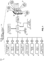
- FIG 1 A first figure.
- a multi-beam multi-function radar antenna system 100 may include a single active electronically scanned array (AESA) 120 mounted at a fixed boresight 410 ( FIG. 4A ) onboard an aircraft 102.
- AESA electronically scanned array
- the plurality of systems may include at least one aircraft system onboard the aircraft configured to 1) receive a specific radar dataset from the single AESA and 2) perform a system function based on the received specific radar dataset, the specific radar dataset provided by one of the first aperture beam and the at least one second aperture beam.
- the plurality of systems may include a vertical weather profiling system 130, a weather detection system 132, a predictive windshear system (PWS) 134, a high-altitude icing detection system 136, a non-cooperative collision avoidance system 138, a runway imaging system 140, a ground mapping system 142, and a geophysical obstacle clearance system (GOC) 144.
- PWS predictive windshear system
- the single AESA 120 may be configured for a segmented aperture enabling multiple beams radiated from multiple subarrays.
- the multiple subarrays may radiate a first aperture beam having a first aperture beam characteristic, a first azimuth, and a first elevation.
- the first aperture beam may be represented by beam A 122 being radiated and received by the single AESA 120.
- the single AESA 120 segmented aperture may also enable a plurality of second aperture beams having a second aperture beam characteristic, a second azimuth, and a second elevation.
- the plurality of second aperture beams may be represented by beams B 124, C 126, and D 128.
- each of the first aperture beam and the plurality of second aperture beams may be independently steered, coherent, and simultaneously radiated from the individual subarrays within the single AESA 120.
- the single AESA 120 may be segmented in a symmetric quad configuration into an exemplary four subarrays including subarray A 162, subarray B 164, Subarray C 166 and subarray D 168 able to independently steer and radiate the plurality of beams 122-128.
- the multi-beam multi-function radar antenna system 100 may include a controller 110 operatively coupled with the single AESA 120 and the at least one aircraft system 130-144.
- the controller 110 may also be coupled with a tangible, non-transitory memory 112 configured to communicate with the controller 110, the tangible, non-transitory memory 112 may have instructions stored therein that, in response to execution by the controller 110, cause the controller 110 to carry out each function associated with the multi-beam multi-function radar antenna system 100.
- the controller 110 may also operatively couple with and antenna control 116 configured for controlling each function of the AESA 120 with more detail in FIG. 3 .
- An aircraft state sensor 118 may function to supply the controller with a state data and phase of flight associated with the aircraft 102.
- the state data may represent an altitude, an airspeed, a climb configuration, a descent configuration, a cruise configuration, an approach configuration, a landing configuration, and a taxi configuration.
- the controller 110 may further couple with a ground clutter suppression (GCS) function 114 configured for continuously suppressing ground clutter as required by each individual aircraft system 130-144.
- GCS ground clutter suppression
- the GCS function 114 may be a function within the controller 110. However, as GCS may be a continuous function relevant to each aircraft system 130-144, it may be represented here as a separate and continuous function.
- the multi-beam multi-function radar antenna system 100 may function to receive a first radar command 234 from a first system 230 of the aircraft systems and a n radar command 254 from at least one n system 250 of the aircraft systems.
- the first radar command 234 may include the first aperture beam characteristics as well as first specific data requirements 232 of the first system 230. Further included in the first radar command 234 may be the first azimuth and the first elevation associated with the first beam 122.
- the controller 110 may also receive the second or n radar command 254 including a required specific radar data 252 for operation.
- the n radar command 254 may similarly include the second aperture beam characteristic, the second azimuth, and the second elevation.
- the controller 110 may segment the single AESA 120 into at least two AESA subarrays 162-168, based on the first radar command 234 and the n radar command 254. In Transmit, the controller may command each of the first, n beam characteristics 212 to transmit the specific beams commanded by the specific aircraft system.
- Each individual subarray 162-168 may transmit and receive the first aperture beam 122 and the n aperture beam 124-128, the first aperture beam 122 having the first aperture beam characteristic based on the first radar command 234 and the n aperture beam 124-128 having the second aperture beam characteristic based on the n radar command 254.
- Each individual subarray 162-168 may transmit and steer, using analog beamforming architecture, the first aperture beam based on the first radar command 234 and the n aperture beam based on the n radar command 254.
- each individual subarray may transmit an individual beam where the received signals may be digitally combined for analysis and additional signal processing.
- the single AESA 120 may receive a first radar return from the first aperture beam and an n radar return from the at n aperture beam 214 and digitally combine the first radar return from the first aperture beam and the n radar return from the n aperture beam via a digital signal processing to create a first specific radar dataset 224 associated with the first system 230 and a n specific radar dataset 222 associated with the n system 250.
- the controller 110 may supply the first system 230 with the first specific radar dataset 224 associated with the first system 230 and the n system 250 with the n specific radar dataset 222 associated with the n system. Once supplied, the controller may execute the system function of the first system 230 based on the first specific radar dataset 224 associated with the first system and the system function of the n system 250 based on the second specific radar dataset 222 associated with the n system.
- the first system 230 may couple with a multi-function display (MFD) 240 enabling a flight crew 242 to visualize a result of the first system 230 and make decisions based on the displayed information.
- MFD multi-function display
- the controller 110 may command the aircraft n system 250 supply a user interface 260 able to configure the n specific radar dataset 222 for consumption and use by a UAS mission computer (MC) 262.
- MC UAS mission computer
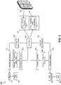
- the Hardware Diagram 300 may include, on a transmit flow, a Beam Steering Computer 320, a radio frequency (RF) Exciter 322, a Transmitter 324, and an n way delay splitter 326 prior to reaching the single AESA 120.
- RF radio frequency
- the antenna control 116 may include Analog Receiver 1 302, Analog Receiver 2 304, Analog Receiver 3 306, and Analog Receiver 4 308 feeding Analog to Digital Converter (ADC) 1 312, ADC 2 314, ADC 3 316 and ADC 4 318.
- ADCs may function to receive the analog signals and digitize to each of the in-phase and quadrature signals I/Q 1 through 4 prior to sending the signals to the controller 110.
- the multi-beam multi-function radar antenna system 100 may enable subarray level receive digital beam forming (DBF) with a multi-subarray configuration where each DBF radiating "element” is a directive 2D scanned analog AESA (e.g., within a subarray) and each subarray may have independent pattern synthesis and beam pointing.
- DBF digital beam forming
- the beam characteristics diagram 400 may indicate exemplary beam characteristics each of the plurality of aperture beams 122-128 may possess.
- each aircraft system 130-144 may command a radar command 234 including an aperture beam power (gain), an AESA segment size (symmetric and asymmetric), a beamwidth (narrow, wide, medium), an azimuth scan (narrow, wide, medium), an elevation scan (narrow, wide, medium), and a nominal side lobe level relative to the peak of the main beam (high / low).
- a radar command 234 including an aperture beam power (gain), an AESA segment size (symmetric and asymmetric), a beamwidth (narrow, wide, medium), an azimuth scan (narrow, wide, medium), an elevation scan (narrow, wide, medium), and a nominal side lobe level relative to the peak of the main beam (high / low).
- the aperture beam power may be commanded by the radar command to one of a high power of approximately 155-205 dBm, a medium power of approximately 103-154 dBm, and a low power of approximately 51-102 dBm.
- the radar command may not only command a specific approximate power, but also an AESA segment size.
- one X Band radiated power may include a 51 - 205 W peak, as the radar is pulled with a (1-25% duty cycle).
- the AESA subarray segment size may determine power available to the associated beam and thus target acquisition available to the associated aircraft system.
- a large aperture size may approximate 0.50 (half) to 1.00 (all) of the total AESA panel 120.
- a large subarray size may be limited to specific circumstances where the aircraft state may be in a position for an immediate action response such as in a windshear event or other scenario where most or all of the radar resources should be devoted to the specific (e.g. PWS) system.
- a medium subarray size may approximate 0.25 (one quarter) to 0.5 (half) of the entirety of the AESA 120.
- a small subarray size may approximate sizes less than 0.25 enabling a plurality of systems to access the limited amount of function within the AESA 120.
- the multi-beam multi-function radar antenna system 100 may enable a full or segmented aperture, single beam sum and difference patterns where each subarray may employ a directive 2D scanned analog AESA.
- the controller 110 may enable pattern synthesis by element-level amplitude and phase adjustment superimposed on the 2D bean steering command.
- the architecture may enable multiple full aperture receive beams with variable azimuth, variable elevation, and beam summing steered in the same direction.
- the controller 110 may synthesize the specific radar dataset from individual subarrays to perform a specific system function.
- the controller 110 may command one or more of the subarrays via the second radar command to control each of an amplitude 428 control and a phase 430 control to enable a radiation pattern synthesis between the two subarrays.
- This function may enable controller execution of the system function of the second system based on the radiation pattern synthesis
- the beamwidth of each aperture beam may be inversely proportional to the aperture beam effective isotropic radiate power (EIRP).
- EIRP aperture beam effective isotropic radiate power
- a high-power aperture beam may possess a narrow beamwidth while a low power aperture beam may possess a wide beamwidth.
- EIRP may be a product of power amplifier power and passive aperture gain.
- the passive aperture gain may be varied in the EIRP as the controller 110 changes the Beamwidth. This assumes that all the of the elements are transmitting a constant RF power. It may also be possible to modulate EIRP by turning the transmit power amplimer circuits associated with each radiating element on and off. Additionally, the controller 110 may adjust the individual power on each transmit RF signal chain feeding the radiating elements.
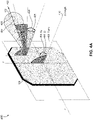
- the single fixed AESA 120 may maintain an AESA plane 408 defined by a vertical axis y and horizontal axis x. Relative to the AESA plane 408, an azimuth 404, an elevation 406 may describe vectors relative to an AESA boresight 410 normal to an AESA plane 408.
- Each individual aperture beam may inherently possess a beam A vector 422 as directed by the radar command 234.
- An exemplary beam A 122 may be defined by the power which may be relative to the AESA segment size. For example, a great AESA segment size may equate to a great available power available to the beam A 122.
- the beam A 122 may also be defined by the beamwidth which may also be dependent on power. For example, a greater power may offer a narrower beamwidth and thus greater range available to identify a specific target while a lesser power (with corresponding smaller aperture segment size) may offer a wider beamwidth and reduced range of target acquisition.
- the beam A 122 may possess the beam A vector 422 including a beam A azimuth 424 and a beam A elevation 426 relative to the AESA boresight 410.
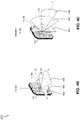
- FIG. 4B may indicate exemplary azimuth scan volumes of each individual aperture beam 122-128 while FIG. 4C may indicate exemplary elevation scan volumes.
- a wide azimuth scan 432 may sweep the aperture beam approximately +/- 80 degrees form the boresight 410
- a medium azimuth scan 434 may sweep the aperture beam approximately +/- 60 degrees from the boresight 410
- a narrow azimuth scan 436 may limit the aperture beam to sweep approximately +/- 30 from the boresight 410.
- each individual aperture beam 122-128 may indicate a wide elevation scan 442 may sweep the aperture beam approximately +/- 80 degrees form the boresight 410, a medium elevation scan 444 may sweep the aperture beam approximately +/- 60 degrees from the boresight 410, while a narrow elevation scan 446 may limit the aperture beam to sweep approximately +/- 30 from the boresight 410.
- the side lobe peak level and the overall noise floor may indicate how much side lobe-induced spurious signals that can cause interference the aircraft system is willing to tolerate and remain functional offering valid data.
- a low side lobe levels may indicate the aircraft system may be susceptible to side lobe interference.
- a ground mapping system operating below 10,000 ft MSL may be susceptible to a side lobe interference given a low power output and proximity to the ground.
- a high side lobe level may indicate a lower susceptibility to side lobe interference.
- a high-altitude icing detection system may be less likely to be affected by side lobe interference given the high altitude and likely smaller elevation scan volume.
- the controller 110 may command a specific subarray configuration based on the received radar commands.
- the weather detection system 132 radar command may include a high power, a large AESA segment size, a narrow beamwidth, and a high side lobe level.
- the vertical weather profiling system 130 may command a medium power, a medium AESA segment size, a narrow beamwidth, a large elevation scan, and a high side lobe level.
- the predictive windshear system 134 may command a high power, a large AESA segment size, a narrow beamwidth, a medium azimuth scan, a medium elevation scan, and a low side lobe level while the high altitude icing detection system 136 may command a high power, a medium AESA segment size, a narrow beamwidth, and a high side lobe level.
- the noncooperative collision avoidance system 138 may command a low power, a small AESA segment size, a wide beamwidth, a wide azimuth scan, a wide elevation scan, and a low side lobe level to detect a second aircraft and the ground mapping system 142 and wherein the second radar command further comprises a low power, a small AESA segment size, a narrow beamwidth, and a low side lobe levels.
- the runway imaging system 140, the ground mapping system 142, and the geophysical obstacle clearance system 144 may command a low power, a small AESA segment size, a wide beamwidth, and a low side lobe level.
- One exemplary approach configuration may include a scenario with the aircraft state being on an approach to intended landing where the weather detection system 132, the PWS 134, and the GOC system 144 are operational and sharing the single AESA 120.
- GCS 114 may be one high priority for use of one of the aperture beams.
- aperture beam D 128 may function to supply information to the controller 110 for GCS a portion of the time while also supplying information to the GOC system 144 during the remaining time.
- the controller 110 has commanded the single AESA 120 to a quad configuration enabling aperture beams C 126 and D 128 available to the GOC system 144.
- the controller 110 has commanded the aperture beam A 122 available to the weather detection system 132 while each of the aperture beams A 122 and B 124 are available to the PWS 134.
- aperture beam A 122 may be allotted to the weather detection system 132 and the PWS 134 on a time sharing basis where a first time slot and beam characteristic is made available to the weather detection system 132 while a second time slot and second bean characteristic are available to the PWS 134.
- the multi-beam multi-function radar antenna system 100 may include an aircraft state sensor configured to provide an aircraft state data and phase of flight to the controller 110.
- the controller 110 may receive the aircraft state data and phase of flight and determine a radar function hierarchy based on the received aircraft state data and phase of flight.
- the aircraft state data may indicate the aircraft is at 2000 ft AGL on an approach in an approach configuration.
- One exemplary radar function hierarchy may have PWS 134 near the top since windshear may be one of the highest threats to a safe landing.
- FIG. 5B may indicate the approach scenario with aperture beams A 122 and B 124 imaging the weather while aperture beams C 126 and D 128 are imaging the terrain.
- each individual aperture beam 122-128 is operating in compliance with the aircraft system radar command 234 254 with respect to power, subarray segment size, etc.
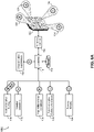
- FIGs. 6A and 6B diagrams of an exemplary cruise aircraft state configuration and scenario 600 in accordance with one embodiment of the inventive concepts disclosed herein are shown.
- five aircraft systems are sharing the limited space and time available on the single AESA 120.
- the vertical weather profiling system 130, the weather detection 132, the HAIC system 136, the NCCA system 138 and the runway imaging system 140 are either space sharing or time sharing the single AESA 120.
- the multi-beam multi-function radar antenna system 100 may enable simultaneous multiple beams for successful GCS 114 as one beam may be configured for the target detection (e.g. rain) and the second beam may be configured to characterize ground clutter.
- the controller 110 may co-process the separate beams to extract the rain signal out of the ground clutter.
- the multi-beam multi-function radar antenna system 100 may enable multiple time coincident beam radar return acquisitions to enable coherency in the return signal to minimize a need for non-coherent return processing.
- the controller 110 may eliminate a requirement for a temporal filter to retain coherency.
- the controller 110 may command a time-based switching of a function of a subarray between compliance with the first radar command and compliance with the second radar command.
- VWP 130 and WX 132 are time sharing aperture beam A 122
- VWP 130, HAIC 136, and NCCA 138 are time sharing aperture beam B 124
- NCCA 138 and RY 140 are time sharing aperture beam C 126
- VWP 130 is time sharing aperture beam D 128 with GCS 114.
- Multiple beams at differing elevations may enable differential dBz measurements for hail detection and icing detection.
- the controller 110 may command a dynamic Inter subarray reconfiguration combining two or more subarrays and tailoring the excitation of the combined subarray.
- one inter subarray reconfiguration may include the controller 110 changing one subarray from GM 142 to WX 132 or alternating the function of of a subarray from one function to another at alternating times.
- the multi-beam multi-function radar antenna system 100 may enable multiple beams of differing pattern characteristic to offer simultaneous radar mode operation. For example, a cosecant squared antenna beam useful for ground mapping may be radiated simultaneous with non-cooperative collision avoidance beam.
- FIG. 6B may indicate aperture beam availability as well as differences in EIRP output of each aperture beam.
- aperture beams A B and D may be used by the VWP 130, output power of each of those may be increased for increased range to scan the vertical entirety of the weather system forward of the aircraft 102.
- aperture beam C 126 may maintain less power output (as well as less segment size within the single AESA 120) for imaging a threat aircraft 602 and accurate operation.
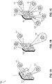
- Exemplary Configurations 700 may indicate symmetric as well as asymmetric subarray segment sizes available as the controller 110 segments the single AESA 120.
- FIG. 7A may indicate a 50% split of the single AESA 120 between aperture beam A 122 and aperture beam B 124.
- FIG. 7B may indicate one asymmetric configuration where aperture beam C 126 may have a higher priority within the hierarchy of radar function than aperture beams A 122 and B 124.
- aperture beam B 124 may have the smallest segment size enabling the smallest output power available for operation.
- the controller 110 may command a dynamic control of the radiation properties (amplitude / phase / bandwidth etc.) of each subarray to create aircraft system application (Contingency Operations) specific beam patterns.
- FIG. 7C may indicate one exemplary configuration with six asymmetric subarrays with corresponding segment sizes.
- One exemplary hierarchy of radar function may include aperture beams A 122 and B 124 being the highest priority, Aperture beams E 726 and F 728 being next on the hierarchy, and aperture beams C 126 and D 128 being at the lowest priority on the hierarchy.
- the controller 110 may adaptively and cooperatively overcome obstructions caused by the angle of the sub-arrays relative to the target of interest. For example, if an air traffic target is over water or in a mountainous region it could take one single beam over water or several beams at different angles to accurately image the target out of the mountainous region depending on where it is relative to the system's sub-arrays. It could also be that one subarray tracking a target is suddenly obstructed given its position on the aircraft whereas another could swap missions with it in order to maintain the same level of situational awareness.
- Method flow 800 may include, at a step 802, receiving a first radar command from a first system onboard the aircraft and a second radar command from at least one second system onboard the aircraft.
- the first system may be associated with a single active electronically scanned array (AESA) mounted at a fixed boresight onboard the aircraft and the first radar command includes a first aperture beam characteristic, a first azimuth, a first elevation, a first amplitude, a first phase, a first side lobe level, and a first polarization associated with a first aperture beam.
- AESA electronically scanned array
- the second radar command may be associated with the single AESA and includes a second aperture beam characteristic, a second azimuth, a second elevation, a second amplitude, a second phase, a second side lobe level, and a second polarization associated with at least one second aperture beam.
- the method may continue, at a step 804, with receiving an aircraft state data from at least one aircraft state data sensor and, at a step 806, determining a hierarchy of radar function based on the aircraft state data.
- the method may continue at a step 808 with in response to the first radar command and the second radar command, segmenting the single AESA into at least two subarrays based on the hierarchy of radar function, to transmit and receive the first aperture beam and the at least one second aperture beam, the first aperture beam having the first aperture beam characteristic based on the first radar command and the at least one second aperture beam having the at least one second aperture beam characteristic based on the second radar command
- a step 810 may include transmitting and steering the first aperture beam based on the first radar command and the at least one second aperture beam based on the second radar command while a step 812 may include receiving a first radar return from the first aperture beam and at least one second radar return from the at least one second aperture beam.
- the method may include, at a step 814, digitally combining the first radar return and the at least one second radar return via a digital signal processing and creating a first specific radar dataset associated with the first system and a second specific radar dataset associated with the at least one second system and at a step 816, supplying the first system with the first specific radar dataset associated with the first system and the at least one second system with the second specific radar dataset associated with the at least one second system.
- the method may then include, at a step 818, executing the system function of the first system based on the first specific radar dataset associated with the first system and the system function of the at least one second system based on the second specific radar dataset associated with the second system.
- embodiments of the inventive concepts disclosed herein may provide a novel solution to enable a single fixed AESA to segment into a plurality of subarrays enabling continuous GCS while simultaneous performing multiple additional functions.
- embodiments of the methods according to the inventive concepts disclosed herein may include one or more of the steps described herein. Further, such steps may be carried out in any desired order and two or more of the steps may be carried out simultaneously with one another. Two or more of the steps disclosed herein may be combined in a single step, and in some embodiments, one or more of the steps may be carried out as two or more sub-steps. Further, other steps or sub-steps may be carried in addition to, or as substitutes to one or more of the steps disclosed herein.
- inventive concepts disclosed herein are well adapted to carry out the objects and to attain the advantages mentioned herein as well as those inherent in the inventive concepts disclosed herein. While presently preferred embodiments of the inventive concepts disclosed herein have been described for purposes of this disclosure, it will be understood that numerous changes may be made which will readily suggest themselves to those skilled in the art and which are accomplished within the broad scope and coverage of the inventive concepts disclosed and claimed herein.
Landscapes
- Engineering & Computer Science (AREA)
- Remote Sensing (AREA)
- Radar, Positioning & Navigation (AREA)
- Physics & Mathematics (AREA)
- General Physics & Mathematics (AREA)
- Computer Networks & Wireless Communication (AREA)
- Aviation & Aerospace Engineering (AREA)
- Electromagnetism (AREA)
- Astronomy & Astrophysics (AREA)
- Radar Systems Or Details Thereof (AREA)
Applications Claiming Priority (1)
| Application Number | Priority Date | Filing Date | Title |
|---|---|---|---|
| US17/211,266 US11835648B2 (en) | 2021-03-24 | 2021-03-24 | Multi-beam multi-function AESA system |
Publications (1)
| Publication Number | Publication Date |
|---|---|
| EP4063894A1 true EP4063894A1 (de) | 2022-09-28 |
Family
ID=80928767
Family Applications (1)
| Application Number | Title | Priority Date | Filing Date |
|---|---|---|---|
| EP22163311.8A Pending EP4063894A1 (de) | 2021-03-24 | 2022-03-21 | Mehrstrahl aesa-multifunktionssystem |
Country Status (2)
| Country | Link |
|---|---|
| US (1) | US11835648B2 (de) |
| EP (1) | EP4063894A1 (de) |
Cited By (1)
| Publication number | Priority date | Publication date | Assignee | Title |
|---|---|---|---|---|
| WO2024182806A1 (en) * | 2023-03-02 | 2024-09-06 | General Radar Corporation | Multi-purpose radar system |
Families Citing this family (5)
| Publication number | Priority date | Publication date | Assignee | Title |
|---|---|---|---|---|
| CN115754968B (zh) * | 2022-11-29 | 2026-04-17 | 航天新气象科技有限公司 | 雷达系统的数据处理方法、雷达系统 |
| US20250012919A1 (en) * | 2023-07-03 | 2025-01-09 | Rockwell Collins, Inc. | Ground clutter suppression and runway imaging via radar ground mapping |
| CN117784078B (zh) * | 2024-02-27 | 2024-05-14 | 中国人民解放军空军预警学院 | 机载雷达空时极化联合自适应处理杂波抑制方法与装置 |
| US12417203B1 (en) | 2024-05-17 | 2025-09-16 | Rockwell Collins, Inc. | High speed, extensible and self-healing data network for AESA RFIC arrays |
| FR3164022A1 (fr) * | 2024-06-28 | 2026-01-02 | Thales | Procédé de fonctionnement d'un radar de détection et radar de détection associé |
Citations (4)
| Publication number | Priority date | Publication date | Assignee | Title |
|---|---|---|---|---|
| US7423578B1 (en) * | 2006-06-09 | 2008-09-09 | Lockheed Martin Corporation | Split aperture array for increased short range target coverage |
| US20130214972A1 (en) * | 2012-02-20 | 2013-08-22 | Rockwell Collins, Inc. | Optimized two panel aesa for aircraft applications |
| US20180259641A1 (en) * | 2017-03-13 | 2018-09-13 | Honeywell International Inc. | Methods for a multi-function electronically steered weather radar |
| US20190113610A1 (en) * | 2017-10-12 | 2019-04-18 | Honeywell International Inc. | Digital active phased array radar |
Family Cites Families (21)
| Publication number | Priority date | Publication date | Assignee | Title |
|---|---|---|---|---|
| US4246585A (en) | 1979-09-07 | 1981-01-20 | The United States Of America As Represented By The Secretary Of The Air Force | Subarray pattern control and null steering for subarray antenna systems |
| GB2504252B (en) | 1992-06-08 | 2014-07-23 | Northern Telecom Ltd | Radar |
| US5563604A (en) | 1995-02-08 | 1996-10-08 | Alliedsignal Inc. | Weather radar using spectral gaussian envelope discrimination for clutter rejection |
| US20050046607A1 (en) * | 2003-09-02 | 2005-03-03 | Alla Volman | Ultra high resolution radar with active electronically scanned antenna (AESA) |
| US7737879B2 (en) | 2006-06-09 | 2010-06-15 | Lockheed Martin Corporation | Split aperture array for increased short range target coverage |
| US7786948B2 (en) | 2007-08-31 | 2010-08-31 | Raytheon Company | Array antenna with embedded subapertures |
| US8089404B2 (en) * | 2008-09-11 | 2012-01-03 | Raytheon Company | Partitioned aperture array antenna |
| EP2391906B1 (de) | 2009-01-30 | 2016-12-07 | Teledyne Australia Pty Ltd. | Vorrichtung und verfahren zur unterstützung vertikal gestarteter fahrzeuge |
| US8952843B1 (en) * | 2012-03-23 | 2015-02-10 | Rockwell Collins, Inc. | Directional AESA with interferometer direction finding mode |
| US9568590B1 (en) | 2013-01-22 | 2017-02-14 | Ball Aerospace & Technologies Corp. | Dynamic thinning of a phased array aperture |
| US9116244B1 (en) * | 2013-02-28 | 2015-08-25 | Rockwell Collins, Inc. | System for and method of weather phenomenon detection using multiple beams |
| US9118112B1 (en) | 2013-03-14 | 2015-08-25 | Rockwell Collins, Inc. | Multi-sensor system and method for vehicles |
| US9680234B2 (en) | 2013-08-28 | 2017-06-13 | Harris Corporation | Dual polarization ground-based phased array antenna system for aircraft communications and associated methods |
| CN103487798A (zh) | 2013-09-09 | 2014-01-01 | 北京理工大学 | 一种相控阵雷达测高方法 |
| US20170045613A1 (en) | 2015-08-11 | 2017-02-16 | Zongbo Wang | 360-degree electronic scan radar for collision avoidance in unmanned aerial vehicles |
| US20170084183A1 (en) | 2015-09-18 | 2017-03-23 | Robert M. Knox | Automatic aircraft separation assurance |
| US10613216B2 (en) | 2016-05-31 | 2020-04-07 | Honeywell International Inc. | Integrated digital active phased array antenna and wingtip collision avoidance system |
| US10050336B2 (en) | 2016-05-31 | 2018-08-14 | Honeywell International Inc. | Integrated digital active phased array antenna and wingtip collision avoidance system |
| US11508247B2 (en) | 2017-07-27 | 2022-11-22 | Honeywell International Inc. | Lidar-based aircraft collision avoidance system |
| US10989802B2 (en) | 2017-10-12 | 2021-04-27 | Honeywell International Inc. | Altimeter with high-resolution radar |
| US11630203B2 (en) * | 2019-06-25 | 2023-04-18 | Raytheon Company | Ground station sensing of weather around an aircraft |
-
2021
- 2021-03-24 US US17/211,266 patent/US11835648B2/en active Active
-
2022
- 2022-03-21 EP EP22163311.8A patent/EP4063894A1/de active Pending
Patent Citations (4)
| Publication number | Priority date | Publication date | Assignee | Title |
|---|---|---|---|---|
| US7423578B1 (en) * | 2006-06-09 | 2008-09-09 | Lockheed Martin Corporation | Split aperture array for increased short range target coverage |
| US20130214972A1 (en) * | 2012-02-20 | 2013-08-22 | Rockwell Collins, Inc. | Optimized two panel aesa for aircraft applications |
| US20180259641A1 (en) * | 2017-03-13 | 2018-09-13 | Honeywell International Inc. | Methods for a multi-function electronically steered weather radar |
| US20190113610A1 (en) * | 2017-10-12 | 2019-04-18 | Honeywell International Inc. | Digital active phased array radar |
Non-Patent Citations (1)
| Title |
|---|
| MOO PETER W ET AL: "Overview of Naval Multifunction RF Systems", 2018 15TH EUROPEAN RADAR CONFERENCE (EURAD), EUROPEAN MICROWAVE ASSOCIATION, 26 September 2018 (2018-09-26), pages 178 - 181, XP033453383, DOI: 10.23919/EURAD.2018.8546521 * |
Cited By (1)
| Publication number | Priority date | Publication date | Assignee | Title |
|---|---|---|---|---|
| WO2024182806A1 (en) * | 2023-03-02 | 2024-09-06 | General Radar Corporation | Multi-purpose radar system |
Also Published As
| Publication number | Publication date |
|---|---|
| US11835648B2 (en) | 2023-12-05 |
| US20220308164A1 (en) | 2022-09-29 |
Similar Documents
| Publication | Publication Date | Title |
|---|---|---|
| US11835648B2 (en) | Multi-beam multi-function AESA system | |
| US11953617B2 (en) | Multi-panel multi-function AESA system | |
| US9116244B1 (en) | System for and method of weather phenomenon detection using multiple beams | |
| Cassidy et al. | High-resolution automotive imaging using MIMO radar and Doppler beam sharpening | |
| US11525910B2 (en) | Synthetic aperture radar apparatus and methods | |
| KR101779900B1 (ko) | 능동 위상 배열 레이더 | |
| US20080291087A1 (en) | Split aperture array for increased short range target coverage | |
| US20240006765A1 (en) | System and method for a digitally beamformed phased array feed | |
| US9568602B1 (en) | Radar system and method of due regard/detect and avoid sensing and weather sensing | |
| US11493620B2 (en) | Distributed monopulse radar antenna array for collision avoidance | |
| AU2007352240A1 (en) | Device & method for 3D height-finding avian radar | |
| Krieger et al. | SIMO and MIMO system architectures and modes for high-resolution ultra-wide-swath SAR imaging | |
| US12405369B2 (en) | Radar imaging method, and radar implementing such a method | |
| US20200103520A1 (en) | Apparatus and methods for a synthetic aperture radar with multi-aperture antenna | |
| Davis et al. | Technical challenges in ultra-wideband radar development for target detection and terrain mapping | |
| Fenner et al. | Test results of a space-time adaptive processing system for airborne early warning radar | |
| Schirru et al. | Advantages of using a C-band Phased Array Feed as a receiver in the Sardinia Radio Telescope for Space Debris monitoring | |
| US20230072466A1 (en) | Radar systems and methods | |
| Huizing et al. | Compact scalable multifunction RF payload for UAVs with FMCW radar and ESM functionality | |
| CN113075654A (zh) | 一种远程雷达探测系统 | |
| US20220187445A1 (en) | Method for Performing SAR Acquisitions with Enhanced Azimuth Resolution | |
| AU2020386840B2 (en) | Beam spoiling | |
| Schurwanz et al. | Using widely separated MIMO antennas for UAV radar direction-of-arrival estimation | |
| Kim et al. | Design and implemetation of Compact 77 GHz Synthetic aperture radar for drone based applications | |
| Shejbal et al. | Active antenna array concepts for precision approach radar |
Legal Events
| Date | Code | Title | Description |
|---|---|---|---|
| PUAI | Public reference made under article 153(3) epc to a published international application that has entered the european phase |
Free format text: ORIGINAL CODE: 0009012 |
|
| STAA | Information on the status of an ep patent application or granted ep patent |
Free format text: STATUS: THE APPLICATION HAS BEEN PUBLISHED |
|
| AK | Designated contracting states |
Kind code of ref document: A1 Designated state(s): AL AT BE BG CH CY CZ DE DK EE ES FI FR GB GR HR HU IE IS IT LI LT LU LV MC MK MT NL NO PL PT RO RS SE SI SK SM TR |
|
| STAA | Information on the status of an ep patent application or granted ep patent |
Free format text: STATUS: REQUEST FOR EXAMINATION WAS MADE |
|
| 17P | Request for examination filed |
Effective date: 20230327 |
|
| RBV | Designated contracting states (corrected) |
Designated state(s): AL AT BE BG CH CY CZ DE DK EE ES FI FR GB GR HR HU IE IS IT LI LT LU LV MC MK MT NL NO PL PT RO RS SE SI SK SM TR |
|
| GRAJ | Information related to disapproval of communication of intention to grant by the applicant or resumption of examination proceedings by the epo deleted |
Free format text: ORIGINAL CODE: EPIDOSDIGR1 |
|
| GRAP | Despatch of communication of intention to grant a patent |
Free format text: ORIGINAL CODE: EPIDOSNIGR1 |
|
| GRAP | Despatch of communication of intention to grant a patent |
Free format text: ORIGINAL CODE: EPIDOSNIGR1 |
|
| STAA | Information on the status of an ep patent application or granted ep patent |
Free format text: STATUS: GRANT OF PATENT IS INTENDED |
|
| RIC1 | Information provided on ipc code assigned before grant |
Ipc: G01S 7/02 20060101AFI20251216BHEP Ipc: G01S 13/00 20060101ALI20251216BHEP Ipc: G01S 13/933 20200101ALI20251216BHEP Ipc: G01S 13/95 20060101ALI20251216BHEP Ipc: G01S 13/90 20060101ALI20251216BHEP Ipc: G01S 13/87 20060101ALI20251216BHEP Ipc: G01S 13/42 20060101ALI20251216BHEP Ipc: G01S 13/44 20060101ALI20251216BHEP Ipc: H01Q 1/28 20060101ALI20251216BHEP Ipc: H01Q 25/00 20060101ALI20251216BHEP Ipc: H01Q 21/06 20060101ALI20251216BHEP Ipc: H01Q 25/02 20060101ALI20251216BHEP Ipc: G01S 13/02 20060101ALN20251216BHEP |
|
| GRAJ | Information related to disapproval of communication of intention to grant by the applicant or resumption of examination proceedings by the epo deleted |
Free format text: ORIGINAL CODE: EPIDOSDIGR1 |
|
| STAA | Information on the status of an ep patent application or granted ep patent |
Free format text: STATUS: REQUEST FOR EXAMINATION WAS MADE |
|
| GRAP | Despatch of communication of intention to grant a patent |
Free format text: ORIGINAL CODE: EPIDOSNIGR1 |
|
| STAA | Information on the status of an ep patent application or granted ep patent |
Free format text: STATUS: GRANT OF PATENT IS INTENDED |
|
| INTG | Intention to grant announced |
Effective date: 20260120 |
|
| GRAS | Grant fee paid |
Free format text: ORIGINAL CODE: EPIDOSNIGR3 |
|
| GRAA | (expected) grant |
Free format text: ORIGINAL CODE: 0009210 |
|
| STAA | Information on the status of an ep patent application or granted ep patent |
Free format text: STATUS: THE PATENT HAS BEEN GRANTED |