EP4063898B1 - Lidar utilisant un modèle de projection retardé pour suivre des objets - Google Patents
Lidar utilisant un modèle de projection retardé pour suivre des objets Download PDFInfo
- Publication number
- EP4063898B1 EP4063898B1 EP21165084.1A EP21165084A EP4063898B1 EP 4063898 B1 EP4063898 B1 EP 4063898B1 EP 21165084 A EP21165084 A EP 21165084A EP 4063898 B1 EP4063898 B1 EP 4063898B1
- Authority
- EP
- European Patent Office
- Prior art keywords
- interest
- projection pattern
- lidar device
- measurement
- measurement location
- Prior art date
- Legal status (The legal status is an assumption and is not a legal conclusion. Google has not performed a legal analysis and makes no representation as to the accuracy of the status listed.)
- Active
Links
Images


Classifications
-
- G—PHYSICS
- G01—MEASURING; TESTING
- G01S—RADIO DIRECTION-FINDING; RADIO NAVIGATION; DETERMINING DISTANCE OR VELOCITY BY USE OF RADIO WAVES; LOCATING OR PRESENCE-DETECTING BY USE OF THE REFLECTION OR RERADIATION OF RADIO WAVES; ANALOGOUS ARRANGEMENTS USING OTHER WAVES
- G01S17/00—Systems using the reflection or reradiation of electromagnetic waves other than radio waves, e.g. lidar systems
- G01S17/02—Systems using the reflection of electromagnetic waves other than radio waves
- G01S17/50—Systems of measurement based on relative movement of target
- G01S17/58—Velocity or trajectory determination systems; Sense-of-movement determination systems
-
- G—PHYSICS
- G01—MEASURING; TESTING
- G01S—RADIO DIRECTION-FINDING; RADIO NAVIGATION; DETERMINING DISTANCE OR VELOCITY BY USE OF RADIO WAVES; LOCATING OR PRESENCE-DETECTING BY USE OF THE REFLECTION OR RERADIATION OF RADIO WAVES; ANALOGOUS ARRANGEMENTS USING OTHER WAVES
- G01S17/00—Systems using the reflection or reradiation of electromagnetic waves other than radio waves, e.g. lidar systems
- G01S17/88—Lidar systems specially adapted for specific applications
- G01S17/89—Lidar systems specially adapted for specific applications for mapping or imaging
-
- G—PHYSICS
- G01—MEASURING; TESTING
- G01S—RADIO DIRECTION-FINDING; RADIO NAVIGATION; DETERMINING DISTANCE OR VELOCITY BY USE OF RADIO WAVES; LOCATING OR PRESENCE-DETECTING BY USE OF THE REFLECTION OR RERADIATION OF RADIO WAVES; ANALOGOUS ARRANGEMENTS USING OTHER WAVES
- G01S7/00—Details of systems according to groups G01S13/00, G01S15/00, G01S17/00
- G01S7/48—Details of systems according to groups G01S13/00, G01S15/00, G01S17/00 of systems according to group G01S17/00
- G01S7/4802—Details of systems according to groups G01S13/00, G01S15/00, G01S17/00 of systems according to group G01S17/00 using analysis of echo signal for target characterisation; Target signature; Target cross-section
-
- G—PHYSICS
- G01—MEASURING; TESTING
- G01S—RADIO DIRECTION-FINDING; RADIO NAVIGATION; DETERMINING DISTANCE OR VELOCITY BY USE OF RADIO WAVES; LOCATING OR PRESENCE-DETECTING BY USE OF THE REFLECTION OR RERADIATION OF RADIO WAVES; ANALOGOUS ARRANGEMENTS USING OTHER WAVES
- G01S7/00—Details of systems according to groups G01S13/00, G01S15/00, G01S17/00
- G01S7/48—Details of systems according to groups G01S13/00, G01S15/00, G01S17/00 of systems according to group G01S17/00
- G01S7/4808—Evaluating distance, position or velocity data
-
- G—PHYSICS
- G01—MEASURING; TESTING
- G01S—RADIO DIRECTION-FINDING; RADIO NAVIGATION; DETERMINING DISTANCE OR VELOCITY BY USE OF RADIO WAVES; LOCATING OR PRESENCE-DETECTING BY USE OF THE REFLECTION OR RERADIATION OF RADIO WAVES; ANALOGOUS ARRANGEMENTS USING OTHER WAVES
- G01S7/00—Details of systems according to groups G01S13/00, G01S15/00, G01S17/00
- G01S7/48—Details of systems according to groups G01S13/00, G01S15/00, G01S17/00 of systems according to group G01S17/00
- G01S7/483—Details of pulse systems
- G01S7/486—Receivers
- G01S7/4865—Time delay measurement, e.g. time-of-flight measurement, time of arrival measurement or determining the exact position of a peak
-
- G—PHYSICS
- G01—MEASURING; TESTING
- G01S—RADIO DIRECTION-FINDING; RADIO NAVIGATION; DETERMINING DISTANCE OR VELOCITY BY USE OF RADIO WAVES; LOCATING OR PRESENCE-DETECTING BY USE OF THE REFLECTION OR RERADIATION OF RADIO WAVES; ANALOGOUS ARRANGEMENTS USING OTHER WAVES
- G01S17/00—Systems using the reflection or reradiation of electromagnetic waves other than radio waves, e.g. lidar systems
- G01S17/86—Combinations of lidar systems with systems other than lidar, radar or sonar, e.g. with direction finders
Definitions
- LiDAR can be used to measure or track objects.
- a user device such as a phone, that is equipped with LiDAR, can detect objects such as people in the region around the user device.
- LiDAR can be used to monitor the relative movement between the objects and the user device, to identify the type of objects or for any other suitable purpose.
- the resolution of such LiDAR devices can be limited by the LiDAR hardware within the device. This can limit the accuracy of the LiDAR and restrict the applications for which the LiDAR can be used.
- US 2019/383942 A1 (D1) relates to a LIDAR-only lock-on tracking system that uses multiple beams arranged in a pattern, or a signal-of-interest (SOI) array, such that the beams do not move appreciably relative to the target during data gathering.
- SOI signal-of-interest
- US 2014/210996 A1 (D2) relates to a method of accurately projecting a laser pattern on a target or work surface and continuously compensating for relative dynamic movement between the laser projector and the target's surface.
- an apparatus comprising means for:
- the means may be for using images obtained by an imaging device to predict the location of the at least one area of interest of the at least one object.
- the means may be for using information obtained from the at least one LiDAR device to predict the location of the at least one area of interest of the at least one object.
- the at least one object may comprise at least part of a person and the location of the area of interest of at least one object is predicted using predictions based on human behaviour.
- the location of the at least one area of interest relative to the at least one LiDAR device may be estimated using information obtained from one or more sensors configured to measure movement of the at least one LiDAR device.
- the means may be for estimating the delay to be added to the transmission of the measurement location projection pattern by calculating one or more expected positions of the at least one area of interest based on the relative velocity between the at least one object and the LiDAR device, calculating a spatial shift for the measurement location projection pattern based on this relative velocity and the current and desired projected measurement locations, and calculating a corresponding time delay to produce the spatial shift.
- the apparatus may comprise means for causing movement of at least part of the at least one LiDAR device to provide relative movement between the at least one object and the at least one LiDAR device.
- the means may be for detecting relative movement between a plurality of objects and the at least one LiDAR device and predicting a location of at least one area of interest for at least some of the plurality of objects and adding a delay to transmission of the measurement location projection pattern to optimise the incidence of measurement locations from the measurement location projection pattern on the areas of interest for the at least some of the plurality of objects.
- the means may be for interpolating between consecutive measurements detected by the at least one LiDAR device to account for the delay added to the transmission of the measurement location projection pattern.
- the measurement location projection pattern may comprise an array of evenly spaced measurement locations.
- an apparatus comprising at least one processor; and at least one memory including computer program code, the at least one memory and the computer program code configured to, with the at least one processor, cause the apparatus at least to perform:
- An electronic device comprising an apparatus as described herein.
- a communications device comprising an apparatus as described herein.
- a vehicle comprising an apparatus as described herein.
- a computer program comprising computer program instructions that, when executed by processing circuitry, cause:
- LiDAR devices can be provided in user devices such as mobile phones or in other types of devices such as vehicles.
- the LiDAR devices can be used to identify nearby objects and/or to determine the relative positions of the objects.
- the LiDAR devices can be used to track the relative positions of the objects and the LiDAR devices.
- the resolution of the LiDAR devices is limited by the hardware of the LiDAR device and the device comprising the LiDAR device. Examples of the disclosure provide improved resolution of the LiDAR by adding a delay to the transmission of a measurement location projection pattern of the LiDAR device.
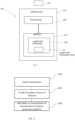
- Fig. 1 shows an example device 101 that could be used to implement examples of the disclosure.
- the device 101 comprises a LiDAR device 103, an apparatus 105 and an imaging device 107.
- the device 101 could be a user device such as a mobile phone or other personal communication device.
- the device 101 could be provided as part of a vehicle or other autonomous device.
- the LiDAR device 103 is being used to measure an object 109.
- the object 109 is a person.
- Other types of objects could be measured in other examples of the disclosure.
- the LiDAR device 103 can comprise any means that can be configured to use LiDAR signals to measure one or more objects 109.
- the LiDAR device 103 can be used to detect the distance and position of one or more objects 109, to identify one or more objects 109 or for any other suitable purpose.
- the LiDAR device 103 can be configured to measure areas of interest of the object 109. This can help to identify the objects 109, and/or can enable the objects 109 to be identified more accurately.
- the areas of interest can comprise an area of the object 109 in which there are more variations or complex information compared to other areas of the object 109.
- the object 109 comprises the face of a person.
- the area around the nose has a larger variation in depth compared to the cheeks. This can enable more information to be obtained from the area around the nose than from the cheeks.
- the areas of interest would comprise the areas around the nose.
- the area of interest of an object 109 could comprise part of the object 109. In other examples the area of interest could comprise the whole of the object 109 or substantially the whole of the object 109.
- the LiDAR device 103 is configured to transmit pulses of light from a laser or other suitable light source.
- the reflections of the light from the one or more objects 109 can be detected and used to measure or provide information about the one or more objects 109.
- the LiDAR device 103 can be configured to transmit a measurement location projection pattern 111.
- the measurement location projection pattern 111 can comprise a plurality of measurement locations that are transmitted by the LiDAR device 103.
- the measurement locations can be one or more areas of light.
- the measurement locations can be areas of light transmitted from a laser or any other suitable light source.
- the areas of light within the measurement location projection pattern 111 can have any suitable shape.
- the areas of light can comprise a plurality of dots and the dots can be provided in an array to provide a dot projection pattern.
- the areas of light within the measurement location projection pattern 111 can be arranged in any suitable pattern.
- the areas of light can be arranged in a regular array comprising a series of regularly spaced columns and rows.
- Other types of arrays could be used in other examples of the disclosure, for example the arrays could comprise a sequence of concentric circles or any other suitable geometric patterns.
- the measurement location projection pattern 111 can comprise an array of evenly spaced, or substantially evenly spaced, measurement locations.
- the measurement location projection pattern 111 When the measurement location projection pattern 111 is incident on an object 109 the light is reflected back towards the LiDAR device 103 or any other suitable detection means.
- the LiDAR device 103, or any other suitable detection means can detect the reflected light and use the timings of the reception of the reflected light signals to measure the location of the object 109. This information can be used to identify the object 109 or to distinguish one type of object from another type of object.
- the identification of the objects 109 could be via the application of an object detection algorithm on the geometries detected and mapped by data obtained by the LiDAR device 103.
- the apparatus 105 that is provided within the device 101 can comprise a controller 203 comprising a processor 205 and memory 207 that can be as shown in Fig. 2 .
- the apparatus 105 can be configured to enable control of the device 101.
- the apparatus 105 can be configured to control the LiDAR device 103 to enable measurement of one or more objects.
- the apparatus 105 can also be configured to control the images that are captured by the imaging device 107 and/or to control any other functions that could be implemented by the device 101.
- the imaging device 107 can comprise any means for capturing an image.
- the imaging device 107 can comprise one or more cameras or any other suitable means for capturing images.
- Fig.1 only one imaging device 107 is shown.
- the device 101 could comprise a plurality of imaging devices 107 that could be positioned in different locations within the device 101.
- the device 101 could comprise a front facing imaging device 107 and a rear facing imaging device 107.
- the imaging device 107 can comprise one or more sensors where the sensors can be configured to detect images.
- the sensors of the imaging device 107 can be coupled to the apparatus 105 to enable detected images to be stored in an image storage module.
- the image storage module could be part of the memory 207 of the apparatus 105.
- the sensors of the imaging device 107 can comprise any suitable type of image sensor.
- the sensor of the imaging device 107 can comprise a digital image sensor such as a charge-coupled-device (CCD) or a complementary metal-oxide-semiconductor (CMOS).
- CCD charge-coupled-device
- CMOS complementary metal-oxide-semiconductor
- the imaging device 107 can be controlled by the apparatus 105 to enable images to be captured. Once an image has been captured it can be stored in the image storage module and/or transmitted to a third party. The images that are captured by the imaging device 107 can be used to identify objects 109 within an image and/or to enable tracking of the objects 109.
- the tracking of the objects 109 comprises determining how the position of the object 109 changes over a period of time. In some examples the tracking of the object 109 can comprise determining a trajectory of the object 109.
- the device 101 could comprise additional components that are not shown in Fig. 1 .
- the device 101 could comprise a power source, one or more transceivers and/or any other suitable components.
- the device 101 could comprise means for causing motion of the LiDAR device 103.
- the means for causing motion of the LiDAR device 103 could be configured to cause motion of just the LiDAR device 103 and/or to cause motion of the whole of the device 101.
- the means for causing motion of the LiDAR device 103 could comprise one or more motors that can be configured to cause a vibration of the LiDAR device 103 and/or the device 101. This vibration can create relative movement between the LiDAR device 103 and the object 109 that is to be measured by the LiDAR device 103.
- Fig. 2 shows an example apparatus 105.
- the apparatus 105 illustrated in Fig. 2 can be a chip or a chip-set.
- the apparatus 105 can be provided within a device 101 such as a mobile phone, personal electronics device or any other suitable type of device 101.
- the apparatus 105 could be provided within a vehicle or other device that monitors the objects 109 within the surroundings.
- the apparatus 105 could be provided within devices 101 as shown in Fig. 1 .
- the apparatus 105 comprises a controller 203.
- the implementation of the controller 203 can be as controller circuitry.
- the controller 203 can be implemented in hardware alone, have certain aspects in software including firmware alone or can be a combination of hardware and software (including firmware).
- the controller 203 can be implemented using instructions that enable hardware functionality, for example, by using executable instructions of a computer program 209 in a general-purpose or special-purpose processor 205 that can be stored on a computer readable storage medium (disk, memory etc.) to be executed by such a processor 205.
- a general-purpose or special-purpose processor 205 that can be stored on a computer readable storage medium (disk, memory etc.) to be executed by such a processor 205.
- the processor 205 is configured to read from and write to the memory 207.
- the processor 205 can also comprise an output interface via which data and/or commands are output by the processor 205 and an input interface via which data and/or commands are input to the processor 205.
- the memory 207 is configured to store a computer program 209 comprising computer program instructions (computer program code 211) that controls the operation of the apparatus 105 when loaded into the processor 205.
- the computer program instructions, of the computer program 209 provide the logic and routines that enable the apparatus 105 to perform the methods illustrated in Figs. 3 and 5 .
- the processor 205 by reading the memory 207 is able to load and execute the computer program 209.
- the delivery mechanism 201 can be, for example, a machine readable medium, a computer-readable medium, a non-transitory computer-readable storage medium, a computer program product, a memory device, a record medium such as a Compact Disc Read-Only Memory (CD-ROM) or a Digital Versatile Disc (DVD) or a solid-state memory, an article of manufacture that comprises or tangibly embodies the computer program 209.
- the delivery mechanism can be a signal configured to reliably transfer the computer program 209.
- the apparatus 105 can propagate or transmit the computer program 209 as a computer data signal.
- the computer program 209 can be transmitted to the apparatus 105 using a wireless protocol such as Bluetooth, Bluetooth Low Energy, Bluetooth Smart, 6LoWPan (IP v 6 over low power personal area networks) ZigBee, ANT+, near field communication (NFC), Radio frequency identification, wireless local area network (wireless LAN) or any other suitable protocol.
- a wireless protocol such as Bluetooth, Bluetooth Low Energy, Bluetooth Smart, 6LoWPan (IP v 6 over low power personal area networks) ZigBee, ANT+, near field communication (NFC), Radio frequency identification, wireless local area network (wireless LAN) or any other suitable protocol.
- the computer program 209 comprises computer program instructions for causing an apparatus 105 to perform at least the following:
- the computer program instructions can be comprised in a computer program 209, a non-transitory computer readable medium, a computer program product, a machine readable medium. In some but not necessarily all examples, the computer program instructions can be distributed over more than one computer program 209.
- processor 205 is illustrated as a single component/circuitry it can be implemented as one or more separate components/circuitry some or all of which can be integrated/removable.
- the processor 205 can be a single core or multi-core processor.
- references to "computer-readable storage medium”, “computer program product”, “tangibly embodied computer program” etc. or a “controller”, “computer”, “processor” etc. should be understood to encompass not only computers having different architectures such as single /multi- processor architectures and sequential (Von Neumann)/parallel architectures but also specialized circuits such as field-programmable gate arrays (FPGA), application specific circuits (ASIC), signal processing devices and other processing circuitry.
- References to computer program, instructions, code etc. should be understood to encompass software for a programmable processor or firmware such as, for example, the programmable content of a hardware device whether instructions for a processor, or configuration settings for a fixed-function device, gate array or programmable logic device etc.
- circuitry can refer to one or more or all of the following:
- circuitry also covers an implementation of merely a hardware circuit or processor and its (or their) accompanying software and/or firmware.
- circuitry also covers, for example and if applicable to the particular claim element, a baseband integrated circuit for a mobile device or a similar integrated circuit in a server, a cellular network device, or other computing or network device.
- the blocks illustrated in Figs. 3 and 5 can represent steps in a method and/or sections of code in the computer program 209.
- the illustration of a particular order to the blocks does not necessarily imply that there is a required or preferred order for the blocks and the order and arrangement of the block can be varied. Furthermore, it can be possible for some blocks to be omitted.
- the method comprises detecting relative movement between at least one object 109 and the LiDAR device 103.
- the relative movement can be caused by movement of the LiDAR device 103, movement of the device 101 that the LiDAR device 103 is comprised within, movement of the object 109 or any combination of these.
- the LiDAR device 103 is configured to provide a measurement location projection pattern 111.
- the measurement location projection pattern 111 comprises a plurality of measurement locations that are transmitted by the LiDAR device 103.
- the measurement locations within the measurement location projection pattern 111 comprise areas of light.
- the areas of light can be arranged in a regular array or in any other suitable configurations.
- Any suitable means can be used to detect the relative movement between the at least one object 109 and the LiDAR device 103.
- the movement can be detected by using any one or more of: images from the imaging device 107, information obtained from the LiDAR device 103, one or more motion sensors or any other suitable means.
- the method comprises predicting a location of at least one area of interest of the at least one object 109 relative to the at least one LiDAR device 103 at a given time.
- any suitable means can be used to identify the one or more areas of interest.
- the apparatus 105 can be configured to obtain images from the imaging device 107. The apparatus 105 could then analyse these images, using pattern recognition, machine learning, computer vision techniques or any other suitable technique, to identify the one or more areas of interest. Other suitable means could be used to identify the areas of interest in other examples of the disclosure.
- the given time can be a time that is a short time interval ahead of the current time.
- the given time could be a time that occurs in less than a second or in one or more second's time (for example, in several seconds' time).
- Any suitable means, or combinations or means, can be used to predict the location of the areas of interest of the object 109.
- the apparatus 105 can be configured to use images obtained by the imaging device 107 to predict the locations of areas of interest of the object 109 at the given point in time. For example, a plurality of images obtained by the imaging device 107 could be used to plot a trajectory of an object 109 and from that trajectory predict where the object 109 will be in a future point in time.
- the apparatus 105 can be configured to use information obtained by the LiDAR device 103 to predict the locations of areas of interest of the object 109 at the given point in time. For example, information from the LiDAR device 103 can be used to plot a trajectory of an object 109 and from that trajectory predict the position of the area of interest at a future point in time.
- the apparatus 105 can be configured to use information obtained by one or more sensors configured to measure movement of the LiDAR device 103 to predict the locations of areas of interest of the object 109 at the given point in time.
- the LiDAR device 103 itself could be moving.
- the user of the device 101 could be walking with the device 101 or a vibrator or other motor could be configured to cause movement of the device 101 or there could be any other suitable motion.
- information from the sensors could be used to predict a trajectory of the LiDAR device 103.
- the LiDAR device 103 could be provided within a vehicle.
- onboard vehicle data about the position and trajectory of the vehicle could be used to predict the positions of the object 109 relative to the LiDAR device 103.
- Such data could comprise data about the current velocity of the vehicle, data relating to a planned route of the vehicle and/or any other suitable data.
- the location of the area of interest of the object 109 can be predicted using predictions based on human behaviour.
- patterns of human behaviour within a given environment can be established. The patterns can be established by monitoring the movements of people over time. For instance, it can be determined that when people walk in to a particular room or other environment they would tend to walk towards a particular location or object within the environment. Or in other examples if a person is performing a known activity such as a sport then this could be used to predict the movement or motion of the person. This information can then be used to predict the movements of the people within the environment.
- the patterns of human behaviour could comprise complex movements such as hand movements. This could enable the examples of the disclosure to be used to recognize hand gestures or other similar inputs.
- the method comprises adding a delay to transmission of the measurement location projection pattern 111 so that one or more measurement locations of the measurement location projection pattern 111 are incident on the at least one area of interest of the at least one object 109 at the given time.
- the delay that is added to the measurement location projection pattern 111 increases the time interval between the transmission of two successive measurement location projection patterns 111. This delay, in combination with the relative movement of the LiDAR device 103 and the object 109, adds a spatial shift to the measurement location projection pattern 111 so as to increase the proportion of measurement locations of the measurement location projection pattern 111 that are incident on the area of interest.
- the delay that is to be added to the measurement location projection pattern 111 can be estimated using any suitable means.
- the delay that is to be added to the transmission of the measurement location projection pattern 111 can be estimated by calculating an expected position of the area of interest based on the object's 109 relative velocity to the LiDAR device. Once the expected position is determined then the method can comprise calculating a spatial shift for the measurement location projection pattern 111 based on this relative velocity and the current and desired projected measurement locations. Once the spatial shift has been calculated a corresponding time delay to produce the spatial shift can then be calculated.
- the apparatus 105 can be configured to interpolate between consecutive measurements detected by the LiDAR device to account for the delay added to the transmission of the measurement location projection pattern 111.
- the interpolation can be used to help to match information obtained from the LiDAR device 103 with other information such as images or videos obtained by the imaging device 107.
- both the LiDAR device 103 and the object 109 could be stationary.
- the apparatus 105 could be configured to cause movement of the LiDAR device 103 so as to provide relative movement between the LiDAR device 103 and the object 109.
- a vibrator, or motor or other means for providing motion could be provided within the device 101. This could be controlled by the apparatus 105 to provide any movement as needed.
- the apparatus 105 could control the vibrations of the device 101 and so generate relative motion between the LiDAR device 103 and the object 109.
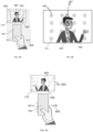
- Figs. 4A to 4C show an example device 101 in use.
- the device 101 is a phone or other hand-held user device.
- Other types of devices could be used in other examples of the disclosure.
- the LiDAR device 103 can be provided within the device 101 and so is not shown in Figs. 4A to 4C .
- the object 109 that is to be measured by the LiDAR device 103 is a person 401.
- the person 401 is positioned in front of the device 101 so that, at least part of, the measurement location projection pattern 111 transmitted by the LiDAR device 103 is incident on the person 401.
- the area of interest of the person 401 could be the user's face. This is the part of the person 401 that can be used to enable the person to be identified or to provide any other suitable information.
- the measurement location projection pattern 111 is a dot projection pattern.
- the measurement locations 403 within the measurement location projection pattern 111 comprise a plurality of dots.
- the plurality of dots 403 are evenly spaced in a plurality of rows and columns. Other shapes and/or arrangements for the measurement locations 403 could be used in other examples of the disclosure.
- Fig. 4A and 4B four rows and columns of the measurement location projection pattern 111 are shown. It is to be appreciated that the measurement location projection pattern 111 could comprise more measurement locations than this. It is also to be appreciated that the measurement location projection pattern 111 and the measurement locations 403 are not shown to scale in Figs. 4A to 4C .
- Fig. 4A the measurement locations 403 of the measurement location projection pattern 111 are shown.
- the person 401 is positioned relative to the device 101 so that the measurement locations 403 of the measurement location projection pattern 111 fall either side of the person's face. In such circumstances the amount of useful information that could be obtained from the LiDAR measurements could be limited.
- Fig. 4A also shows the ideal measurement locations 407 based on the predicted location of the one or more areas of interest.
- the ideal measurement locations 407 are shown more clearly in Fig. 4B which is an enlarged view of the person 401 and the measurement location projection pattern 111.
- the ideal measurement locations 407 are shown as dots with a bold outline while the other measurement locations 403 are shown without the outline.
- the ideal measurement locations 407 are aligned with the person's face.
- the device 101 and the person 401 are moving relative to each other as indicated by the arrows 405.
- This movement can cause a change in position of the person 401 relative to the device 101.
- the movement can be caused by the user of the device 101 moving their hand or by any other suitable means.
- the methods described herein can be applied to predict the location of the one or more areas of interest (in this example, the location of the person's face) relative to the LiDAR device 103 at a given point in time and use that information to estimate a delay that is to be added to the transmission of the measurement location projection pattern 111 so that at least some of the measurement locations 403 within the measurement location projection pattern 111 are shifted to the ideal measurement locations 407.
- Fig. 4C the person 401 and the device 101 have moved relative to each other compared to the example shown in Fig. 4A .
- the person 401 is now facing in a different direction.
- the delay has been added to the measurement location projection pattern 111.
- the delay can be added by implementing an on/off sequence for the LiDAR device 103 or by any other suitable means.
- the delay to the transmission of the measurement location projection pattern 111 has generated a spatial shift in the position of the measurement locations 403 relative to the person 401.
- the spatial shift is such that some of the measurement locations 403 now fall within the area of interest of the person. In this case, at least some of, the measurement locations 403 are incident on the person's face. This can enable the LiDAR measurements to obtain information from the person's face. This causes more measurement locations 403 to be incident on the one or more areas of interest than otherwise would be without the delay and this can provide for more accurate and reliable information from the LiDAR measurements.
- the effects provided by the examples of the disclosure can increase over time as a plurality of different delays are provided to the transmission of a plurality of measurement location projection patterns 111 on a plurality of different occasions.
- the relative movement of the object 109 and the LiDAR device 103 can be monitored over the time period for which the plurality of measurement location projection patterns 111 are transmitted. This can enable a larger number of measurement locations 403 to be incident on the area of interest and so can increase the resolution of the data obtained by the LiDAR device 103.
- the relative movement between the person 401 and the LiDAR device 103 can be generated by the user moving the device 101 and/or by the person 401 moving. In other examples there might not be any relative movement between the person 401 and the device 101. In such examples, in order to generate the relative movement a vibrator or other motor can be configured to vibrate the device 101. This can cause movement of the device 101 and/or the LiDAR device 103 as required.
- Fig. 5 shows another example method that could be implemented using the apparatus 105 and devices 101 described herein.
- the method comprises capturing image data and LiDAR data.
- the captured image data and LiDAR data can be used to determine information about one or more objects 109 within the environment around the device 101. For example, it can be used to determine the location and/or movement of the objects 109.
- the image data can be obtained using the imaging device 107 of the device 101 and/or any other suitable means.
- the LiDAR data can be obtained using the LiDAR device 103 of the device 101 and/or any other suitable means.
- the movement of the device 101 can be predicted.
- the movement of the device 101 can be predicted based on one or more motion sensors such as accelerometers, or any other suitable means.
- the apparatus 105 can be configured to cause the movement of the device 101, for example the apparatus 105 can be configured to activate a motor or vibrator to cause vibration of the device 101.
- the movement of the device 101 can be predicted from the activation of the motor or the vibrator.
- the movement of the LiDAR device 103 could be provided by a motorized configurable device 101.
- the device can be configured to allow for rolling, sliding, folding or other movements of a portion of the device 101 comprising the LiDAR device 103. This reconfiguration can be controlled by a motor or any other suitable means.
- the movement of the device 101 can be predicted from the context of the device 101 and models or patterns of behaviour from the device 101, or other devices, in similar contexts. For instance, if it is determined that the user of the device is performing a gesture that could comprise moving the device 101 as they hold it, then this context information could be used to predict motion of the device 101. Similarly if it is determined that the user of the device 101 is sitting down then this context would correspond to different expected movements compared to a user who is walking or standing.
- the information obtained at block 503 and 505 can be combined to obtain relative motion of the object 109 relative to the device 101.
- this information can be used to predict a location of an area of interest of an object 109 relative to the LiDAR device at a future point in time. This predicted location of the area of interest provides an indication of the desired location for one or more measurement locations 403 at the given point in time.
- the time delay that needs to be applied to the measurement location projection pattern 111 is calculated.
- the time delay is calculated so that when the time delay is added to the measurement location projection pattern 111, at least some of the measurement locations 403 are incident on the desired location.
- the delay can be determined by estimating the spatial shift that needs to be applied to the measurement location projection pattern 111 so that, at least some of the measurement locations 403 are incident on the desired location.
- the time delay is applied to the transmission of the measurement location projection pattern 111.
- the time delay can be applied by controlling power to the LiDAR device 103 or by any other suitable means. Once the delay is added the measurement locations 403 are then incident on the desired location (one or more areas of interest). This can enable more detailed measurements of the object 109 or plurality of objects 109 to be made.
- the LiDAR device 103 is being used to measure a single object 109. It is to be appreciated that in other examples of the disclosure the LiDAR device 103 could be used to measure a plurality of different objects 109. For example, there could be a plurality of people or other objects 109 within the environment around the device 101. In such examples the apparatus 105 can be configured to detect relative movement between the plurality of objects 109 and the LiDAR device 103. This relative movement can be used to predict a location of at least one area of interest for at least some of the plurality of objects 109. In some examples the location of an area of interest could be predicted for all of the objects 109.
- the location of an area of interest could be predicted for just a sub-set of the objects 109.
- a delay is added to transmission of the measurement location projection pattern 111.
- the delay is added so as to optimise, or substantially optimise, the incidence of measurement locations 403 from the measurement location projection pattern 111 on the areas of interest for the at least some of the plurality of objects 109. For instance, it might not be possible for the measurement locations 403 to be incident on an area of interest for all of the objects 109, or for all of the objects 109 within a subset.
- the delay can be added to the transmission of the measurement location projection pattern 111 so that as many measurement locations 403 as possible are incident on the areas of interest.
- the delay could be optimised for each object 109 sequentially. This could lead to a plurality of different delays being added to the transmission of the measurement location projection pattern 111 at different capture instances.
- the object 109 has been a person or part of a person.
- Other types of objects 109 could be measured in other examples of the disclosure.
- the object 109 could be vehicles or other devices. The measurement of these objects could be used to enable collisions to be avoided.
- the objects could comprise animals or other wildlife. In such examples, patterns of behaviour for the animals or wildlife could be used to predict the future location of the object 109 or the area of interest of the object 109. This could help to avoid collisions with the animal or wildlife and/or could enable other useful data to be obtained.
- the objects could be inanimate objects that could be moved during their use, for example tools could be used during construction or home improvements that could have one or more moving parts that could be measured using examples of the disclosure.
- Examples of the disclosure therefore provide for a method of enabling more accurate or informative measurements of objects 109 to be obtained using a LiDAR device 103.
- the additional information can be obtained by applying a delay to the transmission of the measurement location projection pattern 111 there are no changes that need to be made to the hardware of the LiDAR device 103.
- Examples of the disclosure could therefore be implemented using any suitable LiDAR devices 103.
- 'a' or 'the' is used in this document with an inclusive not an exclusive meaning. That is any reference to X comprising a/the Y indicates that X may comprise only one Y or may comprise more than one Y unless the context clearly indicates the contrary. If it is intended to use 'a' or 'the' with an exclusive meaning then it will be made clear in the context. In some circumstances the use of 'at least one' or 'one or more' may be used to emphasis an inclusive meaning but the absence of these terms should not be taken to infer any exclusive meaning.
Landscapes
- Engineering & Computer Science (AREA)
- Physics & Mathematics (AREA)
- Computer Networks & Wireless Communication (AREA)
- General Physics & Mathematics (AREA)
- Radar, Positioning & Navigation (AREA)
- Remote Sensing (AREA)
- Electromagnetism (AREA)
- Optical Radar Systems And Details Thereof (AREA)
Claims (15)
- Appareil (105) comprenant des moyens pour :détecter (301) un déplacement relatif entre au moins un objet (109) et au moins un dispositif LiDAR (103) commandé par l'appareil (105),dans lequel l'au moins un dispositif LiDAR (103) est configuré pour fournir un motif de projection d'emplacement de mesure (111) ;prédire (303) un emplacement d'au moins une zone d'intérêt de l'au moins un objet (109) par rapport à l'au moins un dispositif LiDAR (103) à un moment donné ; etajouter (305) un délai à la transmission du motif de projection d'emplacement de mesure (111) de sorte qu'un ou plusieurs emplacements de mesure du motif de projection d'emplacement de mesure (111) soient incidents sur l'au moins une zone d'intérêt de l'au moins un objet (109) audit moment donné.
- Appareil selon la revendication 1, dans lequel les moyens doivent identifier l'au moins une zone d'intérêt de l'au moins un objet.
- Appareil selon l'une des revendications précédentes, dans lequel les moyens doivent utiliser des images obtenues par un dispositif d'imagerie pour prédire l'emplacement de l'au moins une zone d'intérêt de l'au moins un objet.
- Appareil selon l'une des revendications précédentes, dans lequel les moyens doivent utiliser des informations obtenues à partir de l'au moins un dispositif LiDAR pour prédire l'emplacement de l'au moins une zone d'intérêt de l'au moins un objet.
- Appareil selon l'une des revendications précédentes, dans lequel l'au moins un objet comprend au moins une partie d'une personne, et l'emplacement de la zone d'intérêt d'au moins un objet est prédit à l'aide de prédictions basées sur un comportement humain.
- Appareil selon l'une des revendications précédentes, dans lequel l'emplacement de l'au moins une zone d'intérêt par rapport à l'au moins un dispositif LiDAR est estimé à l'aide d'informations obtenues à partir d'un ou plusieurs capteurs configurés pour mesurer le déplacement de l'au moins un dispositif LiDAR.
- Appareil selon l'une des revendications précédentes, dans lequel les moyens doivent estimer le délai à ajouter à la transmission du motif de projection d'emplacement de mesure en calculant une ou plusieurs positions attendues de l'au moins une zone d'intérêt sur la base de la vitesse relative entre l'au moins un objet et le dispositif LiDAR, en calculant un décalage spatial pour le motif de projection d'emplacement de mesure sur la base de cette vitesse relative et des emplacements de mesure projetés actuels et souhaités, et en calculant un délai de temps correspondant pour produire le décalage spatial.
- Appareil selon l'une des revendications précédentes comprenant des moyens pour provoquer le déplacement d'au moins une partie de l'au moins un dispositif LiDAR pour fournir un déplacement relatif entre l'au moins un objet et l'au moins un dispositif LiDAR.
- Appareil selon l'une des revendications précédentes, dans lequel les moyens doivent détecter un déplacement relatif entre une pluralité d'objets et l'au moins un dispositif LiDAR et prédire un emplacement d'au moins une zone d'intérêt pour au moins certains de la pluralité d'objets, et ajouter un délai à la transmission du motif de projection d'emplacement de mesure pour optimiser l'incidence d'emplacements de mesure à partir du motif de projection d'emplacement de mesure sur la zone d'intérêt pour lesdits au moins certains de la pluralité d'objets.
- Appareil selon l'une des revendications précédentes, dans lequel les moyens doivent effectuer une interpolation entre des mesures consécutives détectées par l'au moins un dispositif LiDAR pour tenir compte du délai ajouté à la transmission du motif de projection d'emplacement de mesure.
- Appareil selon l'une des revendications précédentes, dans lequel le motif de projection d'emplacement de mesure comprend un réseau d'emplacements de mesure régulièrement espacés.
- Procédé comprenant :la détection (301) d'un déplacement relatif entre au moins un objet (109) et au moins un dispositif LiDAR (103) dans lequel l'au moins un dispositif LiDAR (103) est configuré pour fournir un motif de projection d'emplacement de mesure (111) ;la prédiction (303) d'un emplacement d'au moins une zone d'intérêt de l'au moins un objet (109) par rapport à l'au moins un dispositif LiDAR (103) à un moment donné ; etl'ajout (305) d'un délai à la transmission du motif de projection d'emplacement de mesure (111) de sorte qu'un ou plusieurs emplacements de mesure du motif de projection d'emplacement de mesure (111) soient incidents sur l'au moins une zone d'intérêt de l'au moins un objet (109) audit moment donné.
- Procédé selon la revendication 12, comprenant l'identification de l'au moins une zone d'intérêt de l'au moins un objet.
- Programme informatique (209) comprenant des instructions de programme informatique qui, lorsqu'elles sont exécutées par un appareil selon l'une des revendications 1 à 11, provoquent :la détection (301) d'un déplacement relatif entre au moins un objet (109) et au moins un dispositif LiDAR (103) dans lequel l'au moins un dispositif LiDAR (103) est configuré pour fournir un motif de projection d'emplacement de mesure (111) ;la prédiction (303) d'un emplacement d'au moins une zone d'intérêt de l'au moins un objet (109) par rapport à l'au moins un dispositif LiDAR (103) à un moment donné ; etl'ajout (305) d'un délai à la transmission du motif de projection d'emplacement de mesure (111) de sorte qu'un ou plusieurs emplacements de mesure du motif de projection d'emplacement de mesure (111) soient incidents sur l'au moins une zone d'intérêt de l'au moins un objet (109) audit moment donné.
- Programme informatique selon la revendication 14, dans lequel les instructions de programme informatique, lorsqu'elles sont exécutées par une circuiterie de traitement, entraînent l'identification de l'au moins une zone d'intérêt de l'au moins un objet.
Priority Applications (2)
| Application Number | Priority Date | Filing Date | Title |
|---|---|---|---|
| EP21165084.1A EP4063898B1 (fr) | 2021-03-26 | 2021-03-26 | Lidar utilisant un modèle de projection retardé pour suivre des objets |
| US17/697,802 US20220308223A1 (en) | 2021-03-26 | 2022-03-17 | Apparatus, methods and computer programs for using lidar |
Applications Claiming Priority (1)
| Application Number | Priority Date | Filing Date | Title |
|---|---|---|---|
| EP21165084.1A EP4063898B1 (fr) | 2021-03-26 | 2021-03-26 | Lidar utilisant un modèle de projection retardé pour suivre des objets |
Publications (2)
| Publication Number | Publication Date |
|---|---|
| EP4063898A1 EP4063898A1 (fr) | 2022-09-28 |
| EP4063898B1 true EP4063898B1 (fr) | 2024-12-11 |
Family
ID=75252336
Family Applications (1)
| Application Number | Title | Priority Date | Filing Date |
|---|---|---|---|
| EP21165084.1A Active EP4063898B1 (fr) | 2021-03-26 | 2021-03-26 | Lidar utilisant un modèle de projection retardé pour suivre des objets |
Country Status (2)
| Country | Link |
|---|---|
| US (1) | US20220308223A1 (fr) |
| EP (1) | EP4063898B1 (fr) |
Family Cites Families (10)
| Publication number | Priority date | Publication date | Assignee | Title |
|---|---|---|---|---|
| AU2010257107B2 (en) * | 2009-02-20 | 2015-07-09 | Digital Signal Corporation | System and method for generating three dimensional images using lidar and video measurements |
| US9383753B1 (en) * | 2012-09-26 | 2016-07-05 | Google Inc. | Wide-view LIDAR with areas of special attention |
| US9881383B2 (en) * | 2013-01-28 | 2018-01-30 | Virtek Vision International Ulc | Laser projection system with motion compensation and method |
| US20220018961A1 (en) * | 2016-05-18 | 2022-01-20 | James Thomas O'Keeffe | Lidar with adaptive laser point density |
| US10578719B2 (en) * | 2016-05-18 | 2020-03-03 | James Thomas O'Keeffe | Vehicle-integrated LIDAR system |
| CN110114632B (zh) * | 2016-11-30 | 2021-10-29 | 布莱克莫尔传感器和分析有限责任公司 | 用于对光学啁啾距离检测进行多普勒检测和多普勒校正的方法和系统 |
| US10969488B2 (en) * | 2017-03-29 | 2021-04-06 | Luminar Holdco, Llc | Dynamically scanning a field of regard using a limited number of output beams |
| JP2019032206A (ja) * | 2017-08-07 | 2019-02-28 | ソニーセミコンダクタソリューションズ株式会社 | 距離センサ、距離測定装置、および画像センサ |
| US20190383942A1 (en) * | 2018-06-18 | 2019-12-19 | DSCG Solutions, Inc. | Lidar-only lock-on tracking system |
| US11360218B2 (en) * | 2018-09-21 | 2022-06-14 | Aptiv Technologies Limited | Wide field-of-view lidar optical assembly and system |
-
2021
- 2021-03-26 EP EP21165084.1A patent/EP4063898B1/fr active Active
-
2022
- 2022-03-17 US US17/697,802 patent/US20220308223A1/en active Pending
Also Published As
| Publication number | Publication date |
|---|---|
| US20220308223A1 (en) | 2022-09-29 |
| EP4063898A1 (fr) | 2022-09-28 |
Similar Documents
| Publication | Publication Date | Title |
|---|---|---|
| CN108156450B (zh) | 用于校准摄像机的方法、校准设备、校准系统以及机器可读的存储介质 | |
| US9317035B2 (en) | Remote operation system | |
| EP2417577B1 (fr) | Reconstruction tridimensionnelle de scènes et d'objets | |
| TWI481980B (zh) | 電子裝置及其導航方法 | |
| RU151809U1 (ru) | Видеосистема для обеспечения безопасности транспортных средств | |
| KR100759056B1 (ko) | 초음파 센서를 포함하는 장애물 회피 방향 안내 시스템 | |
| JP2020076619A (ja) | 投光制御装置、投光制御方法 | |
| EP3891529A1 (fr) | Ciblage d'objet | |
| US10775242B2 (en) | Tracking and ranging system and method thereof | |
| EP3776143B1 (fr) | Visiocasque et procédé pour réduire le mal des transports induit visuellement dans un affichage à distance connecté | |
| CN104459681B (zh) | 自适应距离估计 | |
| CN111684306A (zh) | 测距装置及点云数据的应用方法、感知系统、移动平台 | |
| EP4063898B1 (fr) | Lidar utilisant un modèle de projection retardé pour suivre des objets | |
| US11076123B2 (en) | Photographing control device, photographing system and photographing control method | |
| JP7135322B2 (ja) | 移動体の監視対象追従制御装置、監視対象追従制御プログラム | |
| KR20210023859A (ko) | 화상 처리 장치, 이동 장치 및 방법, 그리고 프로그램 | |
| US12412306B2 (en) | Information processing apparatus, information processing method, and program | |
| KR20220106217A (ko) | 3차원(3d) 모델링 | |
| JP6293652B2 (ja) | 状態予測システム | |
| EP3906452B1 (fr) | Système de robot-compagnon comprenant un engin a guidage autonome | |
| JP2019192155A (ja) | 画像処理装置、撮影装置、画像処理方法およびプログラム | |
| CN114115350A (zh) | 飞行器的控制方法、装置及设备 | |
| KR102400143B1 (ko) | 스마트폰의 영상통화에 기반하는 원격로봇의 자세 제어방법 및 장치 | |
| CN115979268B (zh) | 异构智能无人集群协同定位方法、设备及存储介质 | |
| EP3605287A1 (fr) | Appareil, procédé et programme informatique permettant de régler des signaux de sortie |
Legal Events
| Date | Code | Title | Description |
|---|---|---|---|
| PUAI | Public reference made under article 153(3) epc to a published international application that has entered the european phase |
Free format text: ORIGINAL CODE: 0009012 |
|
| STAA | Information on the status of an ep patent application or granted ep patent |
Free format text: STATUS: THE APPLICATION HAS BEEN PUBLISHED |
|
| AK | Designated contracting states |
Kind code of ref document: A1 Designated state(s): AL AT BE BG CH CY CZ DE DK EE ES FI FR GB GR HR HU IE IS IT LI LT LU LV MC MK MT NL NO PL PT RO RS SE SI SK SM TR |
|
| STAA | Information on the status of an ep patent application or granted ep patent |
Free format text: STATUS: REQUEST FOR EXAMINATION WAS MADE |
|
| 17P | Request for examination filed |
Effective date: 20230323 |
|
| RBV | Designated contracting states (corrected) |
Designated state(s): AL AT BE BG CH CY CZ DE DK EE ES FI FR GB GR HR HU IE IS IT LI LT LU LV MC MK MT NL NO PL PT RO RS SE SI SK SM TR |
|
| GRAP | Despatch of communication of intention to grant a patent |
Free format text: ORIGINAL CODE: EPIDOSNIGR1 |
|
| STAA | Information on the status of an ep patent application or granted ep patent |
Free format text: STATUS: GRANT OF PATENT IS INTENDED |
|
| RIC1 | Information provided on ipc code assigned before grant |
Ipc: G01S 17/89 20200101ALI20240611BHEP Ipc: G01S 17/58 20060101ALI20240611BHEP Ipc: G01S 7/48 20060101AFI20240611BHEP |
|
| INTG | Intention to grant announced |
Effective date: 20240701 |
|
| GRAS | Grant fee paid |
Free format text: ORIGINAL CODE: EPIDOSNIGR3 |
|
| GRAA | (expected) grant |
Free format text: ORIGINAL CODE: 0009210 |
|
| STAA | Information on the status of an ep patent application or granted ep patent |
Free format text: STATUS: THE PATENT HAS BEEN GRANTED |
|
| AK | Designated contracting states |
Kind code of ref document: B1 Designated state(s): AL AT BE BG CH CY CZ DE DK EE ES FI FR GB GR HR HU IE IS IT LI LT LU LV MC MK MT NL NO PL PT RO RS SE SI SK SM TR |
|
| REG | Reference to a national code |
Ref country code: GB Ref legal event code: FG4D |
|
| REG | Reference to a national code |
Ref country code: CH Ref legal event code: EP |
|
| REG | Reference to a national code |
Ref country code: IE Ref legal event code: FG4D |
|
| REG | Reference to a national code |
Ref country code: DE Ref legal event code: R096 Ref document number: 602021023115 Country of ref document: DE |
|
| REG | Reference to a national code |
Ref country code: LT Ref legal event code: MG9D |
|
| PG25 | Lapsed in a contracting state [announced via postgrant information from national office to epo] |
Ref country code: HR Free format text: LAPSE BECAUSE OF FAILURE TO SUBMIT A TRANSLATION OF THE DESCRIPTION OR TO PAY THE FEE WITHIN THE PRESCRIBED TIME-LIMIT Effective date: 20241211 |
|
| PG25 | Lapsed in a contracting state [announced via postgrant information from national office to epo] |
Ref country code: FI Free format text: LAPSE BECAUSE OF FAILURE TO SUBMIT A TRANSLATION OF THE DESCRIPTION OR TO PAY THE FEE WITHIN THE PRESCRIBED TIME-LIMIT Effective date: 20241211 |
|
| PG25 | Lapsed in a contracting state [announced via postgrant information from national office to epo] |
Ref country code: BG Free format text: LAPSE BECAUSE OF FAILURE TO SUBMIT A TRANSLATION OF THE DESCRIPTION OR TO PAY THE FEE WITHIN THE PRESCRIBED TIME-LIMIT Effective date: 20241211 |
|
| REG | Reference to a national code |
Ref country code: NL Ref legal event code: MP Effective date: 20241211 |
|
| PG25 | Lapsed in a contracting state [announced via postgrant information from national office to epo] |
Ref country code: ES Free format text: LAPSE BECAUSE OF FAILURE TO SUBMIT A TRANSLATION OF THE DESCRIPTION OR TO PAY THE FEE WITHIN THE PRESCRIBED TIME-LIMIT Effective date: 20241211 |
|
| PG25 | Lapsed in a contracting state [announced via postgrant information from national office to epo] |
Ref country code: NO Free format text: LAPSE BECAUSE OF FAILURE TO SUBMIT A TRANSLATION OF THE DESCRIPTION OR TO PAY THE FEE WITHIN THE PRESCRIBED TIME-LIMIT Effective date: 20250311 |
|
| PG25 | Lapsed in a contracting state [announced via postgrant information from national office to epo] |
Ref country code: GR Free format text: LAPSE BECAUSE OF FAILURE TO SUBMIT A TRANSLATION OF THE DESCRIPTION OR TO PAY THE FEE WITHIN THE PRESCRIBED TIME-LIMIT Effective date: 20250312 Ref country code: LV Free format text: LAPSE BECAUSE OF FAILURE TO SUBMIT A TRANSLATION OF THE DESCRIPTION OR TO PAY THE FEE WITHIN THE PRESCRIBED TIME-LIMIT Effective date: 20241211 |
|
| PG25 | Lapsed in a contracting state [announced via postgrant information from national office to epo] |
Ref country code: RS Free format text: LAPSE BECAUSE OF FAILURE TO SUBMIT A TRANSLATION OF THE DESCRIPTION OR TO PAY THE FEE WITHIN THE PRESCRIBED TIME-LIMIT Effective date: 20250311 |
|
| PG25 | Lapsed in a contracting state [announced via postgrant information from national office to epo] |
Ref country code: NL Free format text: LAPSE BECAUSE OF FAILURE TO SUBMIT A TRANSLATION OF THE DESCRIPTION OR TO PAY THE FEE WITHIN THE PRESCRIBED TIME-LIMIT Effective date: 20241211 |
|
| REG | Reference to a national code |
Ref country code: AT Ref legal event code: MK05 Ref document number: 1750805 Country of ref document: AT Kind code of ref document: T Effective date: 20241211 |
|
| PG25 | Lapsed in a contracting state [announced via postgrant information from national office to epo] |
Ref country code: SM Free format text: LAPSE BECAUSE OF FAILURE TO SUBMIT A TRANSLATION OF THE DESCRIPTION OR TO PAY THE FEE WITHIN THE PRESCRIBED TIME-LIMIT Effective date: 20241211 |
|
| PG25 | Lapsed in a contracting state [announced via postgrant information from national office to epo] |
Ref country code: PL Free format text: LAPSE BECAUSE OF FAILURE TO SUBMIT A TRANSLATION OF THE DESCRIPTION OR TO PAY THE FEE WITHIN THE PRESCRIBED TIME-LIMIT Effective date: 20241211 |
|
| PG25 | Lapsed in a contracting state [announced via postgrant information from national office to epo] |
Ref country code: IS Free format text: LAPSE BECAUSE OF FAILURE TO SUBMIT A TRANSLATION OF THE DESCRIPTION OR TO PAY THE FEE WITHIN THE PRESCRIBED TIME-LIMIT Effective date: 20250411 |
|
| PG25 | Lapsed in a contracting state [announced via postgrant information from national office to epo] |
Ref country code: PT Free format text: LAPSE BECAUSE OF FAILURE TO SUBMIT A TRANSLATION OF THE DESCRIPTION OR TO PAY THE FEE WITHIN THE PRESCRIBED TIME-LIMIT Effective date: 20250411 |
|
| PG25 | Lapsed in a contracting state [announced via postgrant information from national office to epo] |
Ref country code: EE Free format text: LAPSE BECAUSE OF FAILURE TO SUBMIT A TRANSLATION OF THE DESCRIPTION OR TO PAY THE FEE WITHIN THE PRESCRIBED TIME-LIMIT Effective date: 20241211 |
|
| PG25 | Lapsed in a contracting state [announced via postgrant information from national office to epo] |
Ref country code: RO Free format text: LAPSE BECAUSE OF FAILURE TO SUBMIT A TRANSLATION OF THE DESCRIPTION OR TO PAY THE FEE WITHIN THE PRESCRIBED TIME-LIMIT Effective date: 20241211 Ref country code: AT Free format text: LAPSE BECAUSE OF FAILURE TO SUBMIT A TRANSLATION OF THE DESCRIPTION OR TO PAY THE FEE WITHIN THE PRESCRIBED TIME-LIMIT Effective date: 20241211 |
|
| PG25 | Lapsed in a contracting state [announced via postgrant information from national office to epo] |
Ref country code: SK Free format text: LAPSE BECAUSE OF FAILURE TO SUBMIT A TRANSLATION OF THE DESCRIPTION OR TO PAY THE FEE WITHIN THE PRESCRIBED TIME-LIMIT Effective date: 20241211 |
|
| PG25 | Lapsed in a contracting state [announced via postgrant information from national office to epo] |
Ref country code: CZ Free format text: LAPSE BECAUSE OF FAILURE TO SUBMIT A TRANSLATION OF THE DESCRIPTION OR TO PAY THE FEE WITHIN THE PRESCRIBED TIME-LIMIT Effective date: 20241211 |
|
| PG25 | Lapsed in a contracting state [announced via postgrant information from national office to epo] |
Ref country code: IT Free format text: LAPSE BECAUSE OF FAILURE TO SUBMIT A TRANSLATION OF THE DESCRIPTION OR TO PAY THE FEE WITHIN THE PRESCRIBED TIME-LIMIT Effective date: 20241211 |
|
| PG25 | Lapsed in a contracting state [announced via postgrant information from national office to epo] |
Ref country code: SE Free format text: LAPSE BECAUSE OF FAILURE TO SUBMIT A TRANSLATION OF THE DESCRIPTION OR TO PAY THE FEE WITHIN THE PRESCRIBED TIME-LIMIT Effective date: 20241211 |
|
| REG | Reference to a national code |
Ref country code: DE Ref legal event code: R097 Ref document number: 602021023115 Country of ref document: DE |
|
| PG25 | Lapsed in a contracting state [announced via postgrant information from national office to epo] |
Ref country code: DK Free format text: LAPSE BECAUSE OF FAILURE TO SUBMIT A TRANSLATION OF THE DESCRIPTION OR TO PAY THE FEE WITHIN THE PRESCRIBED TIME-LIMIT Effective date: 20241211 |
|
| PG25 | Lapsed in a contracting state [announced via postgrant information from national office to epo] |
Ref country code: MC Free format text: LAPSE BECAUSE OF FAILURE TO SUBMIT A TRANSLATION OF THE DESCRIPTION OR TO PAY THE FEE WITHIN THE PRESCRIBED TIME-LIMIT Effective date: 20241211 |
|
| PLBE | No opposition filed within time limit |
Free format text: ORIGINAL CODE: 0009261 |
|
| STAA | Information on the status of an ep patent application or granted ep patent |
Free format text: STATUS: NO OPPOSITION FILED WITHIN TIME LIMIT |
|
| REG | Reference to a national code |
Ref country code: CH Ref legal event code: L10 Free format text: ST27 STATUS EVENT CODE: U-0-0-L10-L00 (AS PROVIDED BY THE NATIONAL OFFICE) Effective date: 20251022 |
|
| REG | Reference to a national code |
Ref country code: CH Ref legal event code: H13 Free format text: ST27 STATUS EVENT CODE: U-0-0-H10-H13 (AS PROVIDED BY THE NATIONAL OFFICE) Effective date: 20251023 |
|
| PG25 | Lapsed in a contracting state [announced via postgrant information from national office to epo] |
Ref country code: LU Free format text: LAPSE BECAUSE OF NON-PAYMENT OF DUE FEES Effective date: 20250326 |
|
| 26N | No opposition filed |
Effective date: 20250912 |
|
| GBPC | Gb: european patent ceased through non-payment of renewal fee |
Effective date: 20250326 |
|
| REG | Reference to a national code |
Ref country code: BE Ref legal event code: MM Effective date: 20250331 |
|
| PG25 | Lapsed in a contracting state [announced via postgrant information from national office to epo] |
Ref country code: GB Free format text: LAPSE BECAUSE OF NON-PAYMENT OF DUE FEES Effective date: 20250326 |
|
| PG25 | Lapsed in a contracting state [announced via postgrant information from national office to epo] |
Ref country code: BE Free format text: LAPSE BECAUSE OF NON-PAYMENT OF DUE FEES Effective date: 20250331 |
|
| PG25 | Lapsed in a contracting state [announced via postgrant information from national office to epo] |
Ref country code: CH Free format text: LAPSE BECAUSE OF NON-PAYMENT OF DUE FEES Effective date: 20250331 |
|
| PG25 | Lapsed in a contracting state [announced via postgrant information from national office to epo] |
Ref country code: IE Free format text: LAPSE BECAUSE OF NON-PAYMENT OF DUE FEES Effective date: 20250326 |
|
| PGFP | Annual fee paid to national office [announced via postgrant information from national office to epo] |
Ref country code: DE Payment date: 20260204 Year of fee payment: 6 |
|
| PGFP | Annual fee paid to national office [announced via postgrant information from national office to epo] |
Ref country code: FR Payment date: 20260209 Year of fee payment: 6 |