EP4063903A1 - Mesure optique de distance selon un procédé de temps de propagation de la lumière - Google Patents
Mesure optique de distance selon un procédé de temps de propagation de la lumière Download PDFInfo
- Publication number
- EP4063903A1 EP4063903A1 EP22156588.0A EP22156588A EP4063903A1 EP 4063903 A1 EP4063903 A1 EP 4063903A1 EP 22156588 A EP22156588 A EP 22156588A EP 4063903 A1 EP4063903 A1 EP 4063903A1
- Authority
- EP
- European Patent Office
- Prior art keywords
- light
- receiving element
- sensor
- deflection
- measurement
- Prior art date
- Legal status (The legal status is an assumption and is not a legal conclusion. Google has not performed a legal analysis and makes no representation as to the accuracy of the status listed.)
- Granted
Links
Images



Classifications
-
- G—PHYSICS
- G01—MEASURING; TESTING
- G01S—RADIO DIRECTION-FINDING; RADIO NAVIGATION; DETERMINING DISTANCE OR VELOCITY BY USE OF RADIO WAVES; LOCATING OR PRESENCE-DETECTING BY USE OF THE REFLECTION OR RERADIATION OF RADIO WAVES; ANALOGOUS ARRANGEMENTS USING OTHER WAVES
- G01S7/00—Details of systems according to groups G01S13/00, G01S15/00, G01S17/00
- G01S7/48—Details of systems according to groups G01S13/00, G01S15/00, G01S17/00 of systems according to group G01S17/00
- G01S7/497—Means for monitoring or calibrating
-
- G—PHYSICS
- G01—MEASURING; TESTING
- G01S—RADIO DIRECTION-FINDING; RADIO NAVIGATION; DETERMINING DISTANCE OR VELOCITY BY USE OF RADIO WAVES; LOCATING OR PRESENCE-DETECTING BY USE OF THE REFLECTION OR RERADIATION OF RADIO WAVES; ANALOGOUS ARRANGEMENTS USING OTHER WAVES
- G01S17/00—Systems using the reflection or reradiation of electromagnetic waves other than radio waves, e.g. lidar systems
- G01S17/02—Systems using the reflection of electromagnetic waves other than radio waves
- G01S17/06—Systems determining position data of a target
- G01S17/08—Systems determining position data of a target for measuring distance only
- G01S17/10—Systems determining position data of a target for measuring distance only using transmission of interrupted, pulse-modulated waves
-
- G—PHYSICS
- G01—MEASURING; TESTING
- G01S—RADIO DIRECTION-FINDING; RADIO NAVIGATION; DETERMINING DISTANCE OR VELOCITY BY USE OF RADIO WAVES; LOCATING OR PRESENCE-DETECTING BY USE OF THE REFLECTION OR RERADIATION OF RADIO WAVES; ANALOGOUS ARRANGEMENTS USING OTHER WAVES
- G01S17/00—Systems using the reflection or reradiation of electromagnetic waves other than radio waves, e.g. lidar systems
- G01S17/02—Systems using the reflection of electromagnetic waves other than radio waves
- G01S17/06—Systems determining position data of a target
- G01S17/42—Simultaneous measurement of distance and other co-ordinates
-
- G—PHYSICS
- G01—MEASURING; TESTING
- G01S—RADIO DIRECTION-FINDING; RADIO NAVIGATION; DETERMINING DISTANCE OR VELOCITY BY USE OF RADIO WAVES; LOCATING OR PRESENCE-DETECTING BY USE OF THE REFLECTION OR RERADIATION OF RADIO WAVES; ANALOGOUS ARRANGEMENTS USING OTHER WAVES
- G01S7/00—Details of systems according to groups G01S13/00, G01S15/00, G01S17/00
- G01S7/48—Details of systems according to groups G01S13/00, G01S15/00, G01S17/00 of systems according to group G01S17/00
- G01S7/481—Constructional features, e.g. arrangements of optical elements
- G01S7/4816—Constructional features, e.g. arrangements of optical elements of receivers alone
-
- G—PHYSICS
- G01—MEASURING; TESTING
- G01S—RADIO DIRECTION-FINDING; RADIO NAVIGATION; DETERMINING DISTANCE OR VELOCITY BY USE OF RADIO WAVES; LOCATING OR PRESENCE-DETECTING BY USE OF THE REFLECTION OR RERADIATION OF RADIO WAVES; ANALOGOUS ARRANGEMENTS USING OTHER WAVES
- G01S7/00—Details of systems according to groups G01S13/00, G01S15/00, G01S17/00
- G01S7/48—Details of systems according to groups G01S13/00, G01S15/00, G01S17/00 of systems according to group G01S17/00
- G01S7/481—Constructional features, e.g. arrangements of optical elements
- G01S7/4817—Constructional features, e.g. arrangements of optical elements relating to scanning
Definitions
- the invention relates to a distance-measuring optoelectronic sensor and a method for optical distance measurement according to the preamble of claim 1 and 14, respectively.
- Optical scanning has long been used in laser scanners.
- a light beam generated by a laser periodically scans the monitored area with the help of a deflection unit and uses a time-of-flight method to measure the distance to the scanned object.
- a pulse method light pulses are sent out and the duration between the time of transmission and reception is measured.
- a phase method a periodic amplitude modulation and measurement of the phase shift between the transmitted and received light takes place.
- the angular position of the deflection unit and thus of the object is determined, and in this way measuring points with distance and angle values in polar coordinates are produced after a sampling period.
- multi-beam scanning in the elevation angle three-dimensional measuring points are generated from a spatial area.
- the scanning requires a certain measurement time, especially in the case of 3D acquisition compared to cameras, but the measurement is concentrated on one point and thus gains range and more reliable measurement values.
- Distance-measuring sensors based on this principle are also called LiDAR sensors (Light Detection and Ranging).
- the scanning motion is achieved by a rotating mirror or mirror wheel with multiple facets. It is also known to rotate the entire measuring head with one or more light transmitters and light receivers, as is the case, for example, in DE 197 57 849 B4 is described. In again other systems, a deflection unit is pivoted back and forth. However, any mechanical movement leads to a certain size and sensitivity to shock as well as susceptibility to maintenance due to wear.
- SPADs are avalanche photodiodes that operate in the so-called Geiger mode. For this purpose, they are biased above the breakdown voltage, so that even a single charge carrier released by a single photon can trigger an uncontrolled avalanche, which then recruits all available charge carriers due to the high field strength. SPADs are not only highly sensitive, but also highly integrable.
- a MEMS mirror is just one of several ways to achieve beam deflection without moving mechanical parts. What these beam deflections have in common is that they generate a movement at the most on a micromechanical level, as in the case of micromirrors, and change their optical properties in each case, for example by applying an electrical voltage, in order to set the deflection angle. There is no motor or mechanically moving parts such as a rotating mirror, a polygon mirror wheel or a swivel mechanism.
- the real measured values show the run-time of the pure light path between the sensor and the object overlaid by various electronic and optical delays. These can differ from receiving channel to receiving channel and are at least partly dynamic drift effects due to aging, temperature and other environmental conditions.
- a known compensation measure is an optical reference measurement. the DE 10 2017 101 501 B3 for example, the light propagation time is determined as the difference between the results of a light propagation time measurement and a reference time measurement. A dedicated reference receiving element is provided for the reference time measurement.
- an optoelectronic sensor which returns at least part of the deflected transmitted light beam to the light receiver with a reference target in certain deflection angles, preferably lying outside the field of view, and uses this reference signal to check whether the deflection is still working.
- the reference signal is not used to correct the time-of-flight measurement and could not be, because the reference signal is only available at certain deflection angles, namely those at which no actual measured value is obtained.
- a reference signal is additionally impressed on the measurement signal by partially reflecting structures.
- these pixels are accepted as dead pixels in favor of the function test of the deflection, the reference signal is separated in the evaluation based on the expectation that it will be detected first, or the reference signal is recovered by collectively averaging several measurements. Insofar as it is still possible to measure with the pixels, this measurement is in any case not corrected using the reference measurement. It's not just in DE 10 2018 124 835 B3 do not proceed in which only the distraction is checked. To do this, the pixel would have to reference itself in a dual function, which is difficult because of the overlapping signals and is completely impossible with SPADs, which are then in their dead time after the reference event for the actual measurement.
- the DE 10 2018 212 529 A1 discloses a method and controller for controlling an emitted light power of a light source of an optical sensor system.
- a LiDAR is briefly mentioned, but not its time-of-flight measurement or even a reference measurement to compensate for drifts.
- a separate sensor element is also used to evaluate the emitted light output.
- a distance-measuring optoelectronic sensor for detecting objects in a detection area and a method for optical distance measurement according to claims 1 and 14, respectively.
- a transmitted light bundle is emitted and the transmitted light bundle reflected by the objects again receive.
- a deflection unit deflects the transmitted light bundle into different deflection angles. The scanning initially follows an arbitrary pattern and can be uniform, but it can also affect certain sub-areas (ROI, region of interest) more frequently and others not at all.
- a light receiver comprises at least two light receiving elements, one of which generates a measurement signal from the emitted light beam and the other generates a reference signal from an internal reference light beam, which is derived internally within the sensor from the transmitted light beam, for example by deflecting a partial cross section or a partial reflection.
- a control and evaluation unit evaluates the measurement signal and the reference signal and determines a light propagation time of the transmitted light bundle that is emitted and received again, from which a measured value for the distance of the touched object can be obtained based on the speed of light.
- the light propagation time determined from the measurement signal is preferably corrected with the reference signal, for example by the reference signal forming a time zero point that starts the light propagation time measurement or from which a start time is determined in the evaluation.
- the reference signal can correct dynamic drifts, since they affect the measurement signal and reference signal equally.
- a constant offset, such as an optical travel path of the reference light bundle is unproblematic in a time-of-flight measurement and can be compensated for by calibration or computational compensation.
- the invention is based on the basic idea that the light receiving elements serve as reference receiving elements for one another in alternating roles. Depending on the deflection angle, a light receiving element therefore functions sometimes as a measurement receiving element for generating the measurement signal and sometimes as a reference receiving element for generating the reference signal.
- the control and evaluation unit makes this functional assignment by reading out the received signal of the respective light-receiving element and treating it as a measurement signal or reference signal.
- these roles are fixed, there are dedicated measurement reception elements and dedicated reference reception elements, for example the first light reception element would always be the measurement reception element and the second light reception element would always be the reference reception element.
- the invention does not know this fixed assignment, at least one light-receiving element generates the measurement signal in one deflection angle and the reference signal in another deflection angle, and this dynamic role reversal preferably applies to both or all light-receiving elements.
- the same pixel receives both the reflected transmitted light beam and the reference light. Besides that the DE 10 2018 124 835 B3 does not use this for a compensation of the time-of-flight measurement, this would be a double function of the same pixel and no dynamically changing referencing for each other according to the invention.
- the invention has the advantage that significantly more robust and accurate distance values can be obtained through the reference measurement. No additional electronic components are required for this, since the existing light receiving elements also perform the reference measurement.
- the actual measurement and reference measurement are decoupled with the dynamically changing roles. They can be evaluated as usual from dedicated reference measurements, and they do not mutually affect one another.
- the control and evaluation unit is preferably designed to scan a line and/or a two-dimensional pattern periodically with the aid of the deflection unit.
- the sensor is a line scanner that scans a plane or a section of a plane.
- a two-dimensional pattern a two-dimensional and therefore more comprehensive scanning is made possible.
- the two-dimensional pattern can be artificially limited to one line, but then a line scanner is still created.
- a typical pattern envisages scanning slightly offset rows or columns one after the other and thus systematically scanning an area. In principle, however, any periodic and non-periodic pattern is conceivable, which, for example, scans certain sub-areas more often than others, up to a random pattern.
- the deflection preferably takes place without moving mechanical parts, at most micromechanical parts.
- the sensor is thus a solid-state scanner or sensor.
- the deflection unit particularly preferably has an MEMS mirror, a switchable liquid crystal element, an optical phased array, an acousto-optical modulator, an electro-optical modulator or a tiltable liquid lens.
- a conventional oscillating or rotating mirror or correspondingly moved measuring head is conceivable.
- a two-way deflection can be composed of two solid-state deflections or a hybrid of a macroscopic deflector and a solid-state deflector.
- the light receiver preferably has a large number of light receiving elements, in particular SPADs, which are each assigned to different deflection angles. Accordingly, no actual scanning principle is used on the receiving side, but rather the entire detection area is recorded at the same time, in which only a specific area is illuminated by the transmitted light bundle.
- the light-receiving elements are preferably SPADs with the advantages mentioned in the introduction of particularly high sensitivity and integration capability.
- the light-receiving elements form in particular a pixel row or pixel matrix, with each pixel being a separate light-receiving element or pixel areas being grouped together to form a type of macro-pixel, which then together form one of the light-receiving elements.
- both a fixed and a dynamic group membership are conceivable.
- At least one light-receiving element is responsible for each deflection angle as the measuring receiving element and at least one other light-receiving element is responsible for the reference receiving element.
- the at least one light receiving element which acts as a measuring receiving element, preferably changes with each deflection angle. Accordingly, there is an assignment of light receiving elements to deflection angles with regard to the function as a measuring receiving element.
- the deflection angles are to be understood here as discretized with a granularity corresponding to the angular resolution of the scanning of the detection area. This assignment is only preferably unambiguous.
- a light receiving element which is not used as a measuring receiving element in this deflection angle acts as the reference receiving element.
- the reference receiving element can also change with each deflection angle.
- each light receiving element is used as a measurement receiving element at one deflection angle and as a reference receiving element at another deflection angle. But that doesn't have to be the case, the assignment as a reference receiving element is freer. That Pattern of the light receiving elements functioning as the reference receiving element depending on the deflection angle can be almost arbitrarily irregular.
- the deflection angle is largely irrelevant for the reference measurement as long as the at least one light receiving element responsible for this deflection angle as the measurement receiving element is kept out of the reference measurement.
- the at least one light receiving element functioning as a reference receiving element does not have to have any special spatial relationship to the respective at least one light receiving element functioning as a measurement receiving element, for example as its neighboring pixel. On the contrary, a certain distance to avoid optical crosstalk is even advantageous.
- a light receiving element is used as a reference receiving element for several different deflection angles and/or a group of light receiving elements or even a group of macropixels of light receiving elements is responsible for the same deflection angle.
- the group can then form the reference receiving element for a different deflection angle in the same composition, in a different partial composition or as a completely different group.
- the consequence of this less ordered assignment is that there can be light receiving elements which are responsible for a deflection angle as a measurement receiving element, but are not used as a reference receiving element for any deflection angle and are therefore not used at all.
- the control and evaluation unit is preferably designed to activate or read out only those light-receiving elements that correspond to the respective current deflection angle.
- a kind of scanning principle is thus also implemented on the receiving side.
- no received signals are generated or evaluated by light-receiving elements which, given the current deflection angle of the transmitted light bundle, cannot contribute to the measurement signal or the reference signal at all. Due to the dynamic role assignment of light receiving elements as measurement receiving element or reference receiving element, a type of double scanning occurs.
- the respectively activated light receiving elements can be understood as an activity spot.
- a first such activity spot of the measuring receiving elements moves on the light receiver according to the deflection of the transmitted light beam and thus typically regularly, for example cyclically, over a line or line by line over a matrix.
- a second activity spot moves according to the respectively associated reference receiving elements. This movement can also be regular, for example with a certain offset. How nice executed, but the assignment of the reference receiving elements is geometrically largely free. That only depends on how the respective reference light bundle is created and is subject to a great deal of creative freedom.
- the activity spot of the reference receiving elements can move irregularly, jump once or multiple times, sometimes remain in the same place for several deflection angles, increase or decrease, split up and be brought together again and the like.
- SPADs as light receiving elements can preferably be switched inactive by lowering the bias voltage below the breakdown voltage. They then lose sensitivity by several orders of magnitude and can therefore be considered switched off. Switching to inactive also has the advantage that no unnecessary avalanches are triggered, which only contribute to power consumption and heat generation. However, it is also possible, independently of the technology, to leave the light-receiving elements that are not required active and merely not to read out their received signal or to ignore it in the evaluation. Instead of at the level of the light receiver, it can be optically ensured beforehand that the light receiving elements that are not required do not receive any light, for example with an electro-optical shutter. However, this does not eliminate dark noise, and this can be a significant factor, especially with SPADs.
- the senor preferably has an optical reference decoupling element in the beam path of the transmitted light beam.
- a part of the already deflected transmitted light bundle or a partial decoupling thereof is fed back internally, ie within the sensor, as the reference light bundle to at least one light receiving element.
- the at least one light receiving element struck by the reference light beam acts as a reference receiving element for the respective deflection angle of the transmitted light beam from which the reference light beam is generated. It is conceivable that the reference light bundle hits additional light-receiving elements that are ignored in the evaluation, but the aim is preferably a reference deflection that is as targeted as possible.
- the optical effect for the decoupling of the reference light beam should initially not be restricted here and include, for example, light deflection or reflection or partial reflection.
- a prism, a light conductor loop or the like is conceivable as a light deflection, for example, which guides part of the transmitted light bundle in a different direction, namely towards the light receiver.
- An at least partially reflecting reference decoupling element throws part of the transmitted light beam back directly or indirectly onto the light receiver.
- the reference decoupling element is able to direct the reference light beam in the different deflection angles onto at least one light-receiving element other than the at least one light-receiving element functioning as a measuring receiving element in this deflection angle.
- the reference decoupling element thus ensures that a suitable reference receiving element is available at every deflection angle.
- the optical reference decoupling element is preferably arranged on a front pane of the sensor or is integrated into the front pane.
- the windscreen encompasses all relevant deflection angles, so that the reference light bundle can be decoupled there for all deflection angles of the deflected transmitted light bundle.
- this gives the windscreen a space- and cost-saving dual function.
- a windshield reflection occurs anyway, usually as a disruptive effect, and this can be used sensibly according to the invention.
- the reference decoupling element is particularly preferably integrated into the front pane, for example as a coating or structuring.
- the reference decoupling element preferably has the shape of at least two circular sections that are shifted relative to one another, in particular one that is pushed into one another.
- This form of the reference decoupling element is particularly preferably combined with the arrangement on or integration into the windscreen.
- the center points of the circular sections are pushed apart laterally, ie in the direction transverse to the connecting line from the light transmitter to the reference decoupling element.
- the inner circle sections that meet at an acute angle are then preferably used, this is referred to as telescoping.
- the emergence can be described in another way, that a circle is divided on the diameter that runs along the mentioned connecting line.
- an asymmetrical variant divides the circle on a secant parallel to the diameter and/or obliquely.
- a circular reference outcoupling element would be the reference light bundle just that light receiving element can meet, which acts in this deflection angle as a measurement receiving element.
- the shape of the reference outcoupling element discussed is intended for a variation of the deflection angle in only one direction.
- the shape is preferably flat, and the reference decoupling element is accordingly formed from cylinder or cone sections.
- a more complex contour in the height direction is conceivable, but no longer necessary, since the reference light bundle is already guided to a suitable light-receiving element in the plane of the circle segments.
- the reference decoupling element preferably has a large number of micromirrors or microprisms. This generates and/or deflects a windshield reflection which, depending on the deflection angle, hits certain light receiving elements for which the transmitted light beam is in the detection area outside the field of view at this deflection angle, which means that they are not needed as measurement receiving elements at this deflection angle and can serve as reference receiving elements.
- the micromirrors or microprisms can be applied to the front pane as a microstructure, or the front pane is produced with this microstructure.
- a separate reference decoupling element is also conceivable. In the latter case, the reference decoupling element is preferably arranged in such a way that it is not struck by the reflected transmitted light bundle.
- the reference decoupling element is then located at a relative height in the beam path of a windscreen reflection, which is outside the beam path of the transmitted light bundle and the reflected transmitted light bundle.
- the sensor preferably has a receiving-side diaphragm arrangement with one diaphragm for each deflection angle. If a separate reference decoupling element with a large number of micromirrors or microprisms is used, the diaphragm arrangement is preferably arranged downstream of this. This effectively suppresses extraneous light in the reference light bundle. However, a corresponding diaphragm arrangement is also useful for other embodiments, which is then suitably arranged in the beam path in front of the light receiver.
- the control and evaluation unit is preferably designed to measure or check the deflection angle from the reference signal. At least one specific light-receiving element is struck by the reference light bundle at the different deflection angles. Thus, the deflection angle can be deduced from the light receiving element, which generates a reference signal.
- the deflection unit can be regulated, the respective measurement receiving elements and/or reference receiving elements can be selected for the respective deflection angles, or the function of the deflection unit and its control can be checked. If the control and evaluation unit does not have sufficient prior knowledge as to which light-receiving element is currently being considered for receiving the reference signal, it can use the received signals to find the light-receiving element that is struck by the reference light bundle. In this search, the reference signal can be distinguished from the measurement signal by the short light propagation time on the only internal light path in the sensor.
- the control and evaluation unit is preferably designed to use the reference signal to check the operability of the deflection unit, the output power of the light transmitter and/or soiling of a windscreen.
- the control and evaluation unit is preferably designed to use the reference signal to check the operability of the deflection unit, the output power of the light transmitter and/or soiling of a windscreen.
- Deviations are caused, for example, by aging or faulty activation of the light transmitter or aging and soiling, in particular of the optical reference element and front pane.
- the reference signal can be undesirably strong and not just weakened, such as in the case of a stronger front screen reflection when it is dirty. Measuring windscreen contamination is in itself a useful function, for example by issuing a corresponding maintenance request.
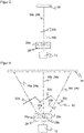
- FIG 1 shows a schematic representation of an optoelectronic sensor 10 or solid-state scanner.
- a light transmitter 12 which preferably has a high-intensity LED or laser light source, transmits a light beam 16 into a detection area 18 through a transmission optics 14 .
- the deflection angle of the transmitted light beam 16 can be changed with the aid of a deflection unit 20 and the transmitted light beam 16 can thus be aligned with a desired variable measuring point 22 .
- a line-shaped or two-dimensional detection area 18 is thereby scanned successively with corresponding scanning patterns, with almost any scanning pattern being conceivable.
- the deflection unit 20 is shown only schematically. There are a wide variety of implementation options, but non-exhaustive examples are a MEMS mirror, a switchable liquid crystal element, an Optical Phased Array (OPA), which, similar to radar technology, can swivel the beam lobe at the output by superimposing many individual transmitters, an acousto-optical modulator, an electro-optical modulator, a liquid lens, in which the boundary layer between two immiscible media can be tilted by controlling an electrode arrangement, or a piezo actuator, which determines a lateral position of the transmission optics 14 or, since the relative position between them is important, of the light transmitter 12 changed.
- OPA Optical Phased Array
- the light transmitter 12 used is a line or matrix with a large number of individual light transmitters that can be controlled individually or in groups, for example a VCSEL array or an arrangement with other light sources such as LEDs or edge emitter laser diodes.
- a transmitted light beam 16 at a specific deflection angle is then generated by targeted activation of specific individual light transmitters.
- the deflection unit 20 in a solid-state scanner manages without macroscopic moving parts.
- a conventional mechanism in the form of a rotating mirror or a movable measuring head is conceivable as an alternative.
- the transmitted light beams 16 now hit objects in the detection area 18 , they are thrown back to the sensor 10 as remitted transmitted light beams 24 .
- the remitted transmitted light beams 24 pass through a receiving optics 26 to a light receiver 28.
- the receiving optics 26, like the transmitting optics 14, are only represented by a simple lens, which is representative of any optics with multi-lens lenses, diaphragms and other optical elements. A reflective or diffractive optic is also conceivable.
- the basic optical structure with a biaxially adjacent light transmitter 12 and light receiver 28 is also not mandatory and can be replaced by any design known per se from single-beam optoelectronic sensors. An example of this is a coaxial arrangement with or without a beam splitter.
- the light receiver 28 has a large number of light receiving elements and is preferably designed as a SPAD array.
- SPADs are highly sensitive and highly integrable, and they offer the ability to become virtually inactive by lowering the bias voltage below the breakdown voltage. As a result, only those SPADs can be activated which correspond to the desired measuring point 22 and thus to the expected one Place of incidence of the remitted transmitted light beams 24 correspond.
- a SPAD array a multiple arrangement of photodiodes or APDs or another line or matrix receiver, for example using CCD or CMOS technology, is conceivable, in which case only specific pixels or pixel groups are read out according to desired measuring points. There is no need for beam deflection on the receiving side.
- the light receiver 28 covers the entire angular range of the desired field of view, but each individual measurement is advantageously limited to the measurement point 22 with high light output and low levels of extraneous light.
- a control and evaluation unit 30 is connected to the light transmitter 12 and the light receiver 28 . This controls the deflection unit 20 in order to direct the transmitted light beam 16 to the desired measuring point 22 in each case.
- the received signals preferably only from the light-receiving elements or SPADs actually illuminated by the reflected transmitted light beam 24, are evaluated in order to determine a light propagation time to the measuring point 22 of the respective object touched in the detection area 18 and from this their distance. It is preferably measured using a pulse-based method (dToF, direct time-of-flight), but pulse averaging with several successively transmitted individual pulses and statistical joint evaluation, for example after accumulation in a histogram or a phase method (iToF, indirect time-of-flight) is also conceivable.
- At least parts of the control and evaluation unit 30 can be integrated with the light transmitter 12 or the light receiver 28 on a common module, such as generating a pattern for the sequence of the deflection or pixel-related evaluations or pre-processing steps.
- a reference path for generating a reference signal for an optical reference measurement is spanned in addition to the actual measurement path with the measurement signal from the reflected transmitted light beam 24 .
- Various optical and electronic propagation delays can falsify the measurement. Possible causes are temperature effects and other environmental influences as well as component fluctuations, which have different effects on the various reception channels and can change during operation. These delays can be compensated for with the aid of the reference signal, for example by the control and evaluation unit 30 determining a start time of the light propagation time measurement from the reference signal or correcting the light propagation time or the reference signal the time measurement starts with time-to-digital converters (TDCs).
- TDCs time-to-digital converters
- the reference signal can be used for gating in which measurement signals are only valid in a time window from the reference signal or the measuring light receiving elements are only active at all or are read out only in this time window. It is also conceivable to derive a signal form from the reference signal and to find this again in the measurement signal in order to distinguish measurement signals and interference signals from one another.
- the Sensor 10 has a reference decoupling element 32 for generating the reference signal.
- the reference decoupling element 32 is arranged here, for example, on a front pane 34 of the sensor 10, through which the transmitted light beam 16 exits and the reflected transmitted light beam 24 enters.
- the reference decoupling element 32 can be arranged inside in the transmission beam path or outside on the front pane 34 or integrated into the front pane 34 . Possible arrangements, configurations and the function of the reference decoupling element 32 will be discussed later with reference to FIG Figures 2-10 explained in more detail.
- the reference decoupling element 32 decouples a reference light beam 36 from the transmitted light beam 16 and returns it to the light receiver 28 on a reference path within the sensor 10 .
- the reference light beam 36 for the respective deflection angle hits a different light-receiving element than the one in whose field of view the measuring point 22 lies.
- a light receiving element acts as a measuring receiving element for generating the measuring signal for determining the light propagation time and another light receiving element as a reference receiving element for generating the reference signal for correcting the light propagation time.
- light receiving elements are activated as a function of the current deflection angle, as described above, not only the respective measurement receiving element is activated, but also the reference receiving element.
- the light receiving elements are used by the control and evaluation unit 30 in alternating roles as measurement receiving element and reference receiving element.
- dedicated reference pixels are not required as is conventional. In most cases, the uncritical assumption is made that the measurement conditions only change negligibly within a scan. But that would have to be assumed for dedicated reference pixels as well.
- the reflected transmitted light beam 24 and the reference light beam 36 can fall on only one pixel or on several pixels of the light receiver 28 . Accordingly, it is not necessary for just one light-receiving element to function as the measuring receiving element or reference receiving element, there can be several. This applies in particular to the reference path, which is not dependent on a narrowly limited field of view corresponding to measurement point 22 . This differentiation is no longer considered in the following, but is included when linguistically only a single light receiving element assumes the role of the measuring receiving element or reference receiving element.
- figure 2 shows a schematic representation of the generation of individually deflected reference light beams 36 by the reference decoupling element 32.
- the reference decoupling element 32 is shown here as a reference plane for the sake of simplicity.
- the main part of the respective transmitted light beam 16a-c passes the reference decoupling element 32 and, when it hits an object 38, is thrown back as a remitted transmitted light beam 24a-c onto a respective light-receiving element 28a-c for the associated deflection angle.
- a proportion is diverted as a reference light beam 36a-c to another light-receiving element 28a-c.
- FIG. 2 The situation is in figure 2 shown by way of example for three deflection angles and light receiving elements 28a-c.
- usually many more light receiving elements are used, which scan the detection area 18 with a much finer grid of deflection angles.
- a line-by-line scanning with only one degree of freedom of the deflection angle is possible, as shown, or alternatively, a planar scan with two degrees of freedom of the deflection angle is possible.
- the beam paths shown at the same time are actually only active one after the other. For example, a transmitted light beam 16a is first emitted to the left and the associated reflected transmitted light beam 24a is received in the left-hand light receiving element 28a.
- a reference light beam 36a coupled out in the process is diverted to the central light-receiving element 28b, and its received signal is used as a reference signal for the measurement signal of the left-hand light-receiving element 28a.
- the deflection unit 20 for the transmitted light beam 16b pivots to the center.
- the middle light receiving element 28b now functions as a measuring receiving element and the right light receiving element 28c as a reference receiving element.
- the transmitted light beam 16c is scanned to the right, with the right-hand light-receiving element 28c supplying the measurement signal and the left-hand light-receiving element 28a supplying the reference signal. The scanning process is then repeated cyclically.
- the order shown is purely an example.
- the only requirement for the reference light beam 36a-c is that it must not impinge on the light-receiving element 28a-c that generates the measurement signal at the current deflection angle.
- the reference decoupling element 32 is preferably integrated into the front pane 34 or at least arranged there. For example, it can have individual partially transparent mirrors or discs or a nanostructure. A suitable beam deflection of the reference light beams 36a-c can also be achieved via the shape. Since the light-receiving elements 28a-c are typically also intended to detect very small signal levels as a measurement signal and are correspondingly sensitive, the decoupling of a very small part of the transmitted light beam 16a-c is already sufficient to generate easily detectable reference light beams 36a-c.
- figure 3 shows a detail of the generation using the example of the reference light beam 36b for the mean deflection angle in the example of FIG figure 2 with only three deflection angles.
- the reference decoupling element 32 was in figure 2 shown only schematically, without going into detail in the illustration how an individual guidance of the reference light beams 36a-c is achieved.
- a tilted reflective element 32b is used as part of the reference output element 32, such as a simple tilted glass pane that may be associated with the front pane 34. A portion of the exiting transmitted light beam 16b is reflected to the right by the reflection element 32b.
- the reflected transmitted light beam 24b hits the central light receiving element 28b, which acts as a measuring receiving element
- the reference light beam 36b hits the right-hand light receiving element 28c, which acts as a reference receiving element.
- the remitted transmitted light beam 24b is also on its return partially reflected away by the reflection element 32b and can then no longer be used. This behavior can be mitigated by an anti-reflective coating.
- figure 4 shows how, instead of just a single reference light beam 36b, all three reference light beams 32a-c can be redirected to a suitable light-receiving element 28a-c by means of a plurality of reflection elements 32a-c in varying inclination.
- the inclinations can be selected in such a way that the assignments are as in figure 2 arise, which will not be explained again.
- the reference decoupling element 32 is, for example, a separate pane or front pane 34 that has been bent several times. With a realistic number of light receiving elements 28a-c, much smaller reflection elements 32a-c and a correspondingly small thickness of the reference decoupling element 32 arise.
- figure 4 shows a conceivable real embodiment, but is primarily intended to clarify the functional principle.
- micro-mirror structures are conceivable.
- the tilting of the individual mirrors can be controlled, for example as MEMS mirrors, but the assignment of the reference light beams 36a-c can also perform the reference function without dynamic changes.
- figure 5 shows a further embodiment of a reference decoupling element 32 for generating individually deflected reference light beams 36a-c.
- the deflection is not achieved by individual structures or reflection elements, but by a suitable geometric shape of the reference decoupling element 32, which can be provided separately or as a front pane 34.
- This shape is given in a top view, ie a section of the reference decoupling element 32, by two circular sections 40a-b pushed into one another.
- a centered single circle 42 and the two generating offset circles 42a-b are also included for illustrative purposes. These are just guidelines, not elements of sensor 10.
- the two circle sections 40a-b meet in a bend.
- the decoupled part of the transmitted light beam 16b is then deflected to both sides as two reference light beams 36b. This does not have to happen in this form in a real sensor 10, but it would still work, since the light-receiving elements 28a;c that are adjacent to the right and left and struck by the reference light beams 36b are different from the light-receiving element 28b responsible for the mean deflection angle as the measuring receiving element.
- figure 6 shows a side view too figure 5 , which is just as side view to the Figures 2 to 4 can be grasped.
- Light transmitter 12 and light receiver 28 are superimposed here.
- the configurations shown above are possible in practice, but were primarily used for corrected display. In any case, light transmitter 12 and light receiver 28 can alternatively be arranged next to one another or coaxially, and reference decoupling element 32 must then be adjusted accordingly.
- the reference decoupling element 32 is tilted so that the reference light beam 36 strikes the light receiver 28 in the height direction. If the front pane 34 has a dual function as a reference decoupling element 32, it is tilted at least in the area where the transmitted light beam 16 exits; in the area where the reflected transmitted light beam 24 re-enters, this is possible but not necessary.
- An optional filter element 44 prevents unwanted crosstalk from the transmission path into the reception path.
- a scanning movement or deflection is shown with only one degree of freedom, ie the orientation of the transmitted light beam 16 varies from left to right.
- a deflection unit 20 with a variation of the deflection angle in two degrees of freedom is also conceivable.
- the reference decoupling element 32 can then also have structures or a specific shape for the added elevation or height direction. However, since a mixing of reflected transmitted light beams 24 and reference light beams 36 already takes place within the described plane, a variation does not necessarily have to be added in the height direction. The course in the height direction can therefore simply be flat as in figure 6 , Which then the reference decoupling element 32 according to figure 5 is composed of cylinder or cone sections.
- the Figures 7a-f illustrate the simulated beam path of the reference light beams 36 when using a figure 5 presented reference decoupling element 32 from two telescoping circular sections 40a-b.
- the front pane 34 itself is the reference decoupling element 32.
- a separate reference decoupling element 32 would also be conceivable, but an additional unused front pane reflection then occurs.
- Figure 7a shows the initial situation without a beam path
- Figure 7b for a transmitted light beam 16 with a deflection angle of 45°
- Figure 7c for transmitted light beams 16 with a deflection angle of 45° and 30°
- Figure 7d for transmitted light beams 16 with deflection angles of 45°, 30° and 15°
- Figure 7e for transmitted light beams 16 with deflection angles of 45°, 30°, 15° and 2°
- figure 7f for transmitted light beams 16 with deflection angles of ⁇ 45°, ⁇ 30°, ⁇ 15° and ⁇ 2°.
- the reference light beam 36 impinges at a suitably offset location where a light receiving element can be selected as the reference receiving element that is not identical to the light receiving element that is used as the measurement receiving element for this deflection angle.
- Figures 8a-f now illustrate the beam path again in a three-dimensional view of simulation results.
- Figure 8a shows the situation for a transmitted light beam 16 with a deflection angle of 45°
- Figure 8b for transmitted light beams 16 with a deflection angle of 45° and 30°
- Figure 8c for transmitted light beams 16 with deflection angles of 45°, 30° and 15°
- Figure 8d for transmitted light beams 16 with deflection angles of 45°, 30°, 15° and 2°
- Figure 8e for transmitted light beams 16 with deflection angles of ⁇ 45°, ⁇ 30°, ⁇ 15° and ⁇ 2°
- Figure 8f a side view too Figure 8e .
- Figures 9a-d f illustrate the simulated beam path of the reference light beams 36 in an embodiment using a reference decoupling element 32 with a large number of prisms or microprisms or a prism array.
- Figure 9a shows the initial situation without a beam path
- Figure 9b for a transmitted light beam 16 with a deflection angle of 30°
- Figure 9c for transmitted light beams 16 with a deflection angle of 30° and 15°
- Figure 9d for transmitted light beams 16 with deflection angles of ⁇ 30°, ⁇ 15° and 0°.
- the reference decoupling element 32 is provided as a separate component in addition to the front pane 34 .
- microprisms can be arranged on the front panel 34 or embossed into the front panel 34 .
- the prisms deflect a windshield reflection onto a suitable light receiving element, which acts as a reference receiving element for this deflection angle. Due to the design of the prisms and their arrangement, an exact position specification for the impingement of the reference light beams 36 on the light receiver 28 is possible.
- the prism arrangement is preferably followed by a diaphragm arrangement, which dampens the scattered light very well and enables a significantly better channel separation.
- such an aperture arrangement in the reception path is also available in the other embodiments, in particular with a reference decoupling element 32 made up of two circular sections 40a-b pushed into one another according to FIGS Figures 5 to 8 advantageous.
- the light receiver 12 can also be arranged without an air gap to the reference decoupling element 32 by a continuous solid body, for example made of glass or plastic with ground edges, is used. The same applies to the light receiver 28.
- Figures 10a-d now illustrate the beam path again in a three-dimensional view of simulation results.
- Figure 10a shows the situation for a transmitted light beam 16 with a deflection angle of 30°
- Figure 10b for transmitted light beams 16 with a deflection angle of 30° and 15°
- Figure 10c for transmitted light beams 16 with deflection angles of 30°, 15° and 0°
- Figure 10d for transmitted light beams 16 with deflection angles of ⁇ 30°, ⁇ 15° and 0°.
- the reference decoupling element 32 has a place in the height direction at which it can decouple reference light beams 36 without also influencing the reflected transmitted light beams 24 in an undesired manner.
- the reference signal can be used for additional functions in addition to correcting the time-of-flight measurement.
- the entire chain of the time-of-flight measurement can be tested by performing a time-of-flight calculation for the reference signal and comparing the result with an expectation. This is then not corrected for drifts, but tests the measuring channel and reveals possible errors. As a result, a functional failure is detected, which is necessary in particular in safety-related applications in order to achieve a higher safety level.
- the transmission power can be monitored. As a result, it is recognized when the light transmitter 12 is aging, exhibiting excessive temperature effects, instead of working in continuous operation in pulsed operation and the like. In this way, soiling of the front pane 34, which can even be localized and which would increase the level of the reference signal due to greater decoupling, is also recognized if necessary. An increase in all receiving channels indicates homogeneous contamination or a fault in the light transmitter 12. By comparing the reference signal with an expected reference signal, it is also possible to determine whether the deflection unit 20 is functioning correctly. If the expected reference signal does not appear, the light transmitter 12 radiates at the wrong deflection angle, which not only prevents the measurement, but is also critical for reasons of eye protection.
- the light transmitter 12 has failed instead of the deflection unit 20, in particular if a received signal with a short light propagation time corresponding to the internal reference path is not detected in any light receiving element. In any case, the sensor 10 cannot be used in this way. A simpler check does not require learned expectations of the reference signal and only determines whether a reference signal is generated at all, without comparing this with an expectation.
- the instantaneous deflection angle can be measured with the reference signals. This in turn is a check of the deflection unit 20 and can be used to readjust it and, if there is a deviation, to align it to the desired deflection angle. Alternatively, the measured values can be corrected in their angular coordinates.
- very specific light receiving elements measure the reference signal, and the assignment to a measurement receiving element is known, so that conclusions can be drawn about the associated deflection angle. It is even possible to find the reference signal without prior knowledge of all the light receiving elements. Since the transmitted light beam 16 radiates only at a specific deflection angle, most of the light-receiving elements remain dark except for an extraneous light background. The measurement signal and the reference signal remain at a higher level, which can be distinguished on the basis of the time response, since the reference path is shorter than all conceivable measurement paths.
Landscapes
- Engineering & Computer Science (AREA)
- Physics & Mathematics (AREA)
- Computer Networks & Wireless Communication (AREA)
- General Physics & Mathematics (AREA)
- Radar, Positioning & Navigation (AREA)
- Remote Sensing (AREA)
- Electromagnetism (AREA)
- Length Measuring Devices By Optical Means (AREA)
- Optical Radar Systems And Details Thereof (AREA)
Applications Claiming Priority (1)
| Application Number | Priority Date | Filing Date | Title |
|---|---|---|---|
| DE102021107193.3A DE102021107193A1 (de) | 2021-03-23 | 2021-03-23 | Optische Abstandsmessung mit einem Lichtlaufzeitverfahren |
Publications (2)
| Publication Number | Publication Date |
|---|---|
| EP4063903A1 true EP4063903A1 (fr) | 2022-09-28 |
| EP4063903B1 EP4063903B1 (fr) | 2023-06-07 |
Family
ID=80953541
Family Applications (1)
| Application Number | Title | Priority Date | Filing Date |
|---|---|---|---|
| EP22156588.0A Active EP4063903B1 (fr) | 2021-03-23 | 2022-02-14 | Mesure optique de distance selon un procédé de temps de propagation de la lumière |
Country Status (2)
| Country | Link |
|---|---|
| EP (1) | EP4063903B1 (fr) |
| DE (1) | DE102021107193A1 (fr) |
Citations (7)
| Publication number | Priority date | Publication date | Assignee | Title |
|---|---|---|---|---|
| DE19757849B4 (de) | 1997-12-24 | 2004-12-23 | Sick Ag | Scanner und Vorrichtung zur optischen Erfassung von Hindernissen, sowie deren Verwendung |
| EP2708914A1 (fr) | 2012-09-18 | 2014-03-19 | Sick Ag | Capteur optoélectronique et procédé de détection d'une carte de profondeur |
| WO2017082830A1 (fr) * | 2015-11-13 | 2017-05-18 | Heptagon Micro Optics Pte. Ltd. | Acquisition de données de distance avec systèmes de télémétrie optique |
| DE102017101501B3 (de) | 2017-01-26 | 2018-01-04 | Sick Ag | Optoelektronischer Sensor und Verfahren zur Bestimmung der Entfernung eines Objekts in einem Überwachungsbereich |
| DE102018124835B3 (de) | 2018-10-09 | 2019-11-07 | Sick Ag | Optoelektronischer Sensor und Verfahren zur Erfassung von Objekten |
| DE102018209844A1 (de) * | 2018-06-19 | 2019-12-19 | Osram Gmbh | Abstandsmesseinheit |
| DE102018212529A1 (de) | 2018-07-27 | 2020-01-30 | Robert Bosch Gmbh | Verfahren und Steuergerät zum Regeln einer emittierten Lichtleistung einer Lichtquelle eines optischen Sensorsystems |
-
2021
- 2021-03-23 DE DE102021107193.3A patent/DE102021107193A1/de not_active Withdrawn
-
2022
- 2022-02-14 EP EP22156588.0A patent/EP4063903B1/fr active Active
Patent Citations (7)
| Publication number | Priority date | Publication date | Assignee | Title |
|---|---|---|---|---|
| DE19757849B4 (de) | 1997-12-24 | 2004-12-23 | Sick Ag | Scanner und Vorrichtung zur optischen Erfassung von Hindernissen, sowie deren Verwendung |
| EP2708914A1 (fr) | 2012-09-18 | 2014-03-19 | Sick Ag | Capteur optoélectronique et procédé de détection d'une carte de profondeur |
| WO2017082830A1 (fr) * | 2015-11-13 | 2017-05-18 | Heptagon Micro Optics Pte. Ltd. | Acquisition de données de distance avec systèmes de télémétrie optique |
| DE102017101501B3 (de) | 2017-01-26 | 2018-01-04 | Sick Ag | Optoelektronischer Sensor und Verfahren zur Bestimmung der Entfernung eines Objekts in einem Überwachungsbereich |
| DE102018209844A1 (de) * | 2018-06-19 | 2019-12-19 | Osram Gmbh | Abstandsmesseinheit |
| DE102018212529A1 (de) | 2018-07-27 | 2020-01-30 | Robert Bosch Gmbh | Verfahren und Steuergerät zum Regeln einer emittierten Lichtleistung einer Lichtquelle eines optischen Sensorsystems |
| DE102018124835B3 (de) | 2018-10-09 | 2019-11-07 | Sick Ag | Optoelektronischer Sensor und Verfahren zur Erfassung von Objekten |
Also Published As
| Publication number | Publication date |
|---|---|
| EP4063903B1 (fr) | 2023-06-07 |
| DE102021107193A1 (de) | 2022-09-29 |
Similar Documents
| Publication | Publication Date | Title |
|---|---|---|
| DE102018124835B3 (de) | Optoelektronischer Sensor und Verfahren zur Erfassung von Objekten | |
| EP3557284A2 (fr) | Capteur optoélectronique et procédé de détermination de la distance | |
| EP1355128B1 (fr) | Alignement automatique d'un senseur | |
| DE102018108340A1 (de) | Optoelektronischer Sensor und Verfahren zur Erfassung und Abstandsbestimmung von Objekten | |
| EP2390620B9 (fr) | Capteur optoélectronique destiné à la détection de bords d'objets | |
| DE102005049471B4 (de) | Entfernungssensor mit Einzelflächenabtastung | |
| DE102010049672B3 (de) | Laser-Doppler-Linien-Distanzsensor zur dreidimensionalen Formvermessung bewegter Festkörper | |
| EP3581958A1 (fr) | Capteur optoélectronique et procédé de détection des données d'image tridimensionnelles | |
| EP3832344B1 (fr) | Capteur optoélectronique et procédé de détection d'un objet | |
| DE102018118653B4 (de) | Optoelektronischer Sensor und Verfahren zum Erfassen eines Objekts | |
| DE102016114432A1 (de) | Optoelektronischer Sensor und Verfahren zur Erfassung eines Objekts | |
| EP3798671B1 (fr) | Capteur optoélectronique et procédé de détection d'objets | |
| EP3660539A1 (fr) | Capteur optoélectronique et procédé de détection d'objets | |
| DE102021111949B4 (de) | Vorrichtung zur scannenden Messung des Abstands zu einem Objekt | |
| EP4184202B1 (fr) | Capteur optoélectronique | |
| DE102008021465A1 (de) | Entfernungsmesssystem | |
| EP3519858B1 (fr) | Unité de balayage d'un dispositif de réception et d'émission optique d'un dispositif de détection optique d'un véhicule | |
| WO2020200691A1 (fr) | Réfractomètre et procédé de détermination de l'indice de réfraction d'un fluide de procédé au moyen d'un réfractomètre | |
| EP4063903B1 (fr) | Mesure optique de distance selon un procédé de temps de propagation de la lumière | |
| EP4063902A1 (fr) | Capteur optoélectronique et procédé de détection d'objets | |
| DE102021203829A1 (de) | Reichweitenoptimiertes LiDAR-System sowie LiDAR-Vorrichtung (110) und Steuereinrichtung für ein solches LiDAR-System | |
| DE102017129100B4 (de) | Optoelektronischer Sensor und Verfahren zur Erfassung eines Überwachungsbereichs | |
| EP1959271B1 (fr) | Agencement de capteur optoélectrique et procédé de vérification du mode de fonctionnement et/ou de l'ajustement d'un agencement de capteur optoélectronique | |
| DE102016213427A1 (de) | LiDAR mit nachgeführtem Erfassungsbereich | |
| EP4465096B1 (fr) | Rideau de lumière |
Legal Events
| Date | Code | Title | Description |
|---|---|---|---|
| PUAI | Public reference made under article 153(3) epc to a published international application that has entered the european phase |
Free format text: ORIGINAL CODE: 0009012 |
|
| STAA | Information on the status of an ep patent application or granted ep patent |
Free format text: STATUS: REQUEST FOR EXAMINATION WAS MADE |
|
| 17P | Request for examination filed |
Effective date: 20220729 |
|
| AK | Designated contracting states |
Kind code of ref document: A1 Designated state(s): AL AT BE BG CH CY CZ DE DK EE ES FI FR GB GR HR HU IE IS IT LI LT LU LV MC MK MT NL NO PL PT RO RS SE SI SK SM TR |
|
| STAA | Information on the status of an ep patent application or granted ep patent |
Free format text: STATUS: EXAMINATION IS IN PROGRESS |
|
| 17Q | First examination report despatched |
Effective date: 20221025 |
|
| GRAP | Despatch of communication of intention to grant a patent |
Free format text: ORIGINAL CODE: EPIDOSNIGR1 |
|
| STAA | Information on the status of an ep patent application or granted ep patent |
Free format text: STATUS: GRANT OF PATENT IS INTENDED |
|
| INTG | Intention to grant announced |
Effective date: 20230213 |
|
| GRAS | Grant fee paid |
Free format text: ORIGINAL CODE: EPIDOSNIGR3 |
|
| GRAA | (expected) grant |
Free format text: ORIGINAL CODE: 0009210 |
|
| STAA | Information on the status of an ep patent application or granted ep patent |
Free format text: STATUS: THE PATENT HAS BEEN GRANTED |
|
| AK | Designated contracting states |
Kind code of ref document: B1 Designated state(s): AL AT BE BG CH CY CZ DE DK EE ES FI FR GB GR HR HU IE IS IT LI LT LU LV MC MK MT NL NO PL PT RO RS SE SI SK SM TR |
|
| REG | Reference to a national code |
Ref country code: GB Ref legal event code: FG4D Free format text: NOT ENGLISH |
|
| REG | Reference to a national code |
Ref country code: CH Ref legal event code: EP Ref country code: AT Ref legal event code: REF Ref document number: 1576750 Country of ref document: AT Kind code of ref document: T Effective date: 20230615 |
|
| REG | Reference to a national code |
Ref country code: DE Ref legal event code: R096 Ref document number: 502022000026 Country of ref document: DE |
|
| REG | Reference to a national code |
Ref country code: LT Ref legal event code: MG9D |
|
| REG | Reference to a national code |
Ref country code: NL Ref legal event code: MP Effective date: 20230607 |
|
| PG25 | Lapsed in a contracting state [announced via postgrant information from national office to epo] |
Ref country code: SE Free format text: LAPSE BECAUSE OF FAILURE TO SUBMIT A TRANSLATION OF THE DESCRIPTION OR TO PAY THE FEE WITHIN THE PRESCRIBED TIME-LIMIT Effective date: 20230607 Ref country code: NO Free format text: LAPSE BECAUSE OF FAILURE TO SUBMIT A TRANSLATION OF THE DESCRIPTION OR TO PAY THE FEE WITHIN THE PRESCRIBED TIME-LIMIT Effective date: 20230907 Ref country code: ES Free format text: LAPSE BECAUSE OF FAILURE TO SUBMIT A TRANSLATION OF THE DESCRIPTION OR TO PAY THE FEE WITHIN THE PRESCRIBED TIME-LIMIT Effective date: 20230607 |
|
| PG25 | Lapsed in a contracting state [announced via postgrant information from national office to epo] |
Ref country code: RS Free format text: LAPSE BECAUSE OF FAILURE TO SUBMIT A TRANSLATION OF THE DESCRIPTION OR TO PAY THE FEE WITHIN THE PRESCRIBED TIME-LIMIT Effective date: 20230607 Ref country code: NL Free format text: LAPSE BECAUSE OF FAILURE TO SUBMIT A TRANSLATION OF THE DESCRIPTION OR TO PAY THE FEE WITHIN THE PRESCRIBED TIME-LIMIT Effective date: 20230607 Ref country code: LV Free format text: LAPSE BECAUSE OF FAILURE TO SUBMIT A TRANSLATION OF THE DESCRIPTION OR TO PAY THE FEE WITHIN THE PRESCRIBED TIME-LIMIT Effective date: 20230607 Ref country code: LT Free format text: LAPSE BECAUSE OF FAILURE TO SUBMIT A TRANSLATION OF THE DESCRIPTION OR TO PAY THE FEE WITHIN THE PRESCRIBED TIME-LIMIT Effective date: 20230607 Ref country code: HR Free format text: LAPSE BECAUSE OF FAILURE TO SUBMIT A TRANSLATION OF THE DESCRIPTION OR TO PAY THE FEE WITHIN THE PRESCRIBED TIME-LIMIT Effective date: 20230607 Ref country code: GR Free format text: LAPSE BECAUSE OF FAILURE TO SUBMIT A TRANSLATION OF THE DESCRIPTION OR TO PAY THE FEE WITHIN THE PRESCRIBED TIME-LIMIT Effective date: 20230908 |
|
| PG25 | Lapsed in a contracting state [announced via postgrant information from national office to epo] |
Ref country code: FI Free format text: LAPSE BECAUSE OF FAILURE TO SUBMIT A TRANSLATION OF THE DESCRIPTION OR TO PAY THE FEE WITHIN THE PRESCRIBED TIME-LIMIT Effective date: 20230607 |
|
| PG25 | Lapsed in a contracting state [announced via postgrant information from national office to epo] |
Ref country code: SK Free format text: LAPSE BECAUSE OF FAILURE TO SUBMIT A TRANSLATION OF THE DESCRIPTION OR TO PAY THE FEE WITHIN THE PRESCRIBED TIME-LIMIT Effective date: 20230607 |
|
| PG25 | Lapsed in a contracting state [announced via postgrant information from national office to epo] |
Ref country code: IS Free format text: LAPSE BECAUSE OF FAILURE TO SUBMIT A TRANSLATION OF THE DESCRIPTION OR TO PAY THE FEE WITHIN THE PRESCRIBED TIME-LIMIT Effective date: 20231007 |
|
| PG25 | Lapsed in a contracting state [announced via postgrant information from national office to epo] |
Ref country code: SM Free format text: LAPSE BECAUSE OF FAILURE TO SUBMIT A TRANSLATION OF THE DESCRIPTION OR TO PAY THE FEE WITHIN THE PRESCRIBED TIME-LIMIT Effective date: 20230607 Ref country code: SK Free format text: LAPSE BECAUSE OF FAILURE TO SUBMIT A TRANSLATION OF THE DESCRIPTION OR TO PAY THE FEE WITHIN THE PRESCRIBED TIME-LIMIT Effective date: 20230607 Ref country code: RO Free format text: LAPSE BECAUSE OF FAILURE TO SUBMIT A TRANSLATION OF THE DESCRIPTION OR TO PAY THE FEE WITHIN THE PRESCRIBED TIME-LIMIT Effective date: 20230607 Ref country code: PT Free format text: LAPSE BECAUSE OF FAILURE TO SUBMIT A TRANSLATION OF THE DESCRIPTION OR TO PAY THE FEE WITHIN THE PRESCRIBED TIME-LIMIT Effective date: 20231009 Ref country code: IS Free format text: LAPSE BECAUSE OF FAILURE TO SUBMIT A TRANSLATION OF THE DESCRIPTION OR TO PAY THE FEE WITHIN THE PRESCRIBED TIME-LIMIT Effective date: 20231007 Ref country code: EE Free format text: LAPSE BECAUSE OF FAILURE TO SUBMIT A TRANSLATION OF THE DESCRIPTION OR TO PAY THE FEE WITHIN THE PRESCRIBED TIME-LIMIT Effective date: 20230607 Ref country code: CZ Free format text: LAPSE BECAUSE OF FAILURE TO SUBMIT A TRANSLATION OF THE DESCRIPTION OR TO PAY THE FEE WITHIN THE PRESCRIBED TIME-LIMIT Effective date: 20230607 |
|
| PG25 | Lapsed in a contracting state [announced via postgrant information from national office to epo] |
Ref country code: PL Free format text: LAPSE BECAUSE OF FAILURE TO SUBMIT A TRANSLATION OF THE DESCRIPTION OR TO PAY THE FEE WITHIN THE PRESCRIBED TIME-LIMIT Effective date: 20230607 |
|
| REG | Reference to a national code |
Ref country code: DE Ref legal event code: R097 Ref document number: 502022000026 Country of ref document: DE |
|
| PLBE | No opposition filed within time limit |
Free format text: ORIGINAL CODE: 0009261 |
|
| STAA | Information on the status of an ep patent application or granted ep patent |
Free format text: STATUS: NO OPPOSITION FILED WITHIN TIME LIMIT |
|
| PG25 | Lapsed in a contracting state [announced via postgrant information from national office to epo] |
Ref country code: DK Free format text: LAPSE BECAUSE OF FAILURE TO SUBMIT A TRANSLATION OF THE DESCRIPTION OR TO PAY THE FEE WITHIN THE PRESCRIBED TIME-LIMIT Effective date: 20230607 |
|
| PG25 | Lapsed in a contracting state [announced via postgrant information from national office to epo] |
Ref country code: SI Free format text: LAPSE BECAUSE OF FAILURE TO SUBMIT A TRANSLATION OF THE DESCRIPTION OR TO PAY THE FEE WITHIN THE PRESCRIBED TIME-LIMIT Effective date: 20230607 |
|
| 26N | No opposition filed |
Effective date: 20240308 |
|
| PG25 | Lapsed in a contracting state [announced via postgrant information from national office to epo] |
Ref country code: SI Free format text: LAPSE BECAUSE OF FAILURE TO SUBMIT A TRANSLATION OF THE DESCRIPTION OR TO PAY THE FEE WITHIN THE PRESCRIBED TIME-LIMIT Effective date: 20230607 Ref country code: IT Free format text: LAPSE BECAUSE OF FAILURE TO SUBMIT A TRANSLATION OF THE DESCRIPTION OR TO PAY THE FEE WITHIN THE PRESCRIBED TIME-LIMIT Effective date: 20230607 |
|
| PG25 | Lapsed in a contracting state [announced via postgrant information from national office to epo] |
Ref country code: MC Free format text: LAPSE BECAUSE OF FAILURE TO SUBMIT A TRANSLATION OF THE DESCRIPTION OR TO PAY THE FEE WITHIN THE PRESCRIBED TIME-LIMIT Effective date: 20230607 |
|
| PG25 | Lapsed in a contracting state [announced via postgrant information from national office to epo] |
Ref country code: LU Free format text: LAPSE BECAUSE OF NON-PAYMENT OF DUE FEES Effective date: 20240214 |
|
| PG25 | Lapsed in a contracting state [announced via postgrant information from national office to epo] |
Ref country code: LU Free format text: LAPSE BECAUSE OF NON-PAYMENT OF DUE FEES Effective date: 20240214 |
|
| PG25 | Lapsed in a contracting state [announced via postgrant information from national office to epo] |
Ref country code: BG Free format text: LAPSE BECAUSE OF FAILURE TO SUBMIT A TRANSLATION OF THE DESCRIPTION OR TO PAY THE FEE WITHIN THE PRESCRIBED TIME-LIMIT Effective date: 20230607 |
|
| PG25 | Lapsed in a contracting state [announced via postgrant information from national office to epo] |
Ref country code: BG Free format text: LAPSE BECAUSE OF FAILURE TO SUBMIT A TRANSLATION OF THE DESCRIPTION OR TO PAY THE FEE WITHIN THE PRESCRIBED TIME-LIMIT Effective date: 20230607 |
|
| REG | Reference to a national code |
Ref country code: BE Ref legal event code: MM Effective date: 20240229 |
|
| PG25 | Lapsed in a contracting state [announced via postgrant information from national office to epo] |
Ref country code: BE Free format text: LAPSE BECAUSE OF NON-PAYMENT OF DUE FEES Effective date: 20240229 |
|
| PG25 | Lapsed in a contracting state [announced via postgrant information from national office to epo] |
Ref country code: IE Free format text: LAPSE BECAUSE OF NON-PAYMENT OF DUE FEES Effective date: 20240214 |
|
| PG25 | Lapsed in a contracting state [announced via postgrant information from national office to epo] |
Ref country code: IE Free format text: LAPSE BECAUSE OF NON-PAYMENT OF DUE FEES Effective date: 20240214 Ref country code: BE Free format text: LAPSE BECAUSE OF NON-PAYMENT OF DUE FEES Effective date: 20240229 |
|
| PG25 | Lapsed in a contracting state [announced via postgrant information from national office to epo] |
Ref country code: CY Free format text: LAPSE BECAUSE OF FAILURE TO SUBMIT A TRANSLATION OF THE DESCRIPTION OR TO PAY THE FEE WITHIN THE PRESCRIBED TIME-LIMIT; INVALID AB INITIO Effective date: 20220214 |
|
| PG25 | Lapsed in a contracting state [announced via postgrant information from national office to epo] |
Ref country code: TR Free format text: LAPSE BECAUSE OF FAILURE TO SUBMIT A TRANSLATION OF THE DESCRIPTION OR TO PAY THE FEE WITHIN THE PRESCRIBED TIME-LIMIT Effective date: 20230607 |
|
| REG | Reference to a national code |
Ref country code: CH Ref legal event code: U11 Free format text: ST27 STATUS EVENT CODE: U-0-0-U10-U11 (AS PROVIDED BY THE NATIONAL OFFICE) Effective date: 20260301 |
|
| PGFP | Annual fee paid to national office [announced via postgrant information from national office to epo] |
Ref country code: GB Payment date: 20260219 Year of fee payment: 5 |
|
| PGFP | Annual fee paid to national office [announced via postgrant information from national office to epo] |
Ref country code: DE Payment date: 20260217 Year of fee payment: 5 |
|
| PGFP | Annual fee paid to national office [announced via postgrant information from national office to epo] |
Ref country code: AT Payment date: 20260301 Year of fee payment: 5 |
|
| PGFP | Annual fee paid to national office [announced via postgrant information from national office to epo] |
Ref country code: FR Payment date: 20260223 Year of fee payment: 5 |
|
| PGFP | Annual fee paid to national office [announced via postgrant information from national office to epo] |
Ref country code: CH Payment date: 20260301 Year of fee payment: 5 |