EP4064316B1 - Elektrische schutzvorrichtung und elektrische schalttafel mit einer solchen elektrischen schutzvorrichtung - Google Patents
Elektrische schutzvorrichtung und elektrische schalttafel mit einer solchen elektrischen schutzvorrichtung Download PDFInfo
- Publication number
- EP4064316B1 EP4064316B1 EP22164262.2A EP22164262A EP4064316B1 EP 4064316 B1 EP4064316 B1 EP 4064316B1 EP 22164262 A EP22164262 A EP 22164262A EP 4064316 B1 EP4064316 B1 EP 4064316B1
- Authority
- EP
- European Patent Office
- Prior art keywords
- stirrup
- lever
- configuration
- switching mechanism
- electrical
- Prior art date
- Legal status (The legal status is an assumption and is not a legal conclusion. Google has not performed a legal analysis and makes no representation as to the accuracy of the status listed.)
- Active
Links
Images





Classifications
-
- H—ELECTRICITY
- H01—ELECTRIC ELEMENTS
- H01H—ELECTRIC SWITCHES; RELAYS; SELECTORS; EMERGENCY PROTECTIVE DEVICES
- H01H71/00—Details of the protective switches or relays covered by groups H01H73/00 - H01H83/00
- H01H71/10—Operating or release mechanisms
- H01H71/50—Manual reset mechanisms which may be also used for manual release
- H01H71/52—Manual reset mechanisms which may be also used for manual release actuated by lever
- H01H71/526—Manual reset mechanisms which may be also used for manual release actuated by lever the lever forming a toggle linkage with a second lever, the free end of which is directly and releasably engageable with a contact structure
-
- H—ELECTRICITY
- H01—ELECTRIC ELEMENTS
- H01H—ELECTRIC SWITCHES; RELAYS; SELECTORS; EMERGENCY PROTECTIVE DEVICES
- H01H73/00—Protective overload circuit-breaking switches in which excess current opens the contacts by automatic release of mechanical energy stored by previous operation of a hand reset mechanism
- H01H73/02—Details
- H01H73/04—Contacts
-
- H—ELECTRICITY
- H01—ELECTRIC ELEMENTS
- H01H—ELECTRIC SWITCHES; RELAYS; SELECTORS; EMERGENCY PROTECTIVE DEVICES
- H01H71/00—Details of the protective switches or relays covered by groups H01H73/00 - H01H83/00
- H01H71/02—Housings; Casings; Bases; Mountings
- H01H71/0207—Mounting or assembling the different parts of the circuit breaker
-
- H—ELECTRICITY
- H01—ELECTRIC ELEMENTS
- H01H—ELECTRIC SWITCHES; RELAYS; SELECTORS; EMERGENCY PROTECTIVE DEVICES
- H01H83/00—Protective switches, e.g. circuit-breaking switches, or protective relays operated by abnormal electrical conditions otherwise than solely by excess current
- H01H83/20—Protective switches, e.g. circuit-breaking switches, or protective relays operated by abnormal electrical conditions otherwise than solely by excess current operated by excess current as well as by some other abnormal electrical condition
-
- H—ELECTRICITY
- H01—ELECTRIC ELEMENTS
- H01H—ELECTRIC SWITCHES; RELAYS; SELECTORS; EMERGENCY PROTECTIVE DEVICES
- H01H83/00—Protective switches, e.g. circuit-breaking switches, or protective relays operated by abnormal electrical conditions otherwise than solely by excess current
- H01H83/20—Protective switches, e.g. circuit-breaking switches, or protective relays operated by abnormal electrical conditions otherwise than solely by excess current operated by excess current as well as by some other abnormal electrical condition
- H01H83/22—Protective switches, e.g. circuit-breaking switches, or protective relays operated by abnormal electrical conditions otherwise than solely by excess current operated by excess current as well as by some other abnormal electrical condition the other condition being imbalance of two or more currents or voltages
-
- H—ELECTRICITY
- H01—ELECTRIC ELEMENTS
- H01H—ELECTRIC SWITCHES; RELAYS; SELECTORS; EMERGENCY PROTECTIVE DEVICES
- H01H83/00—Protective switches, e.g. circuit-breaking switches, or protective relays operated by abnormal electrical conditions otherwise than solely by excess current
- H01H83/20—Protective switches, e.g. circuit-breaking switches, or protective relays operated by abnormal electrical conditions otherwise than solely by excess current operated by excess current as well as by some other abnormal electrical condition
- H01H83/22—Protective switches, e.g. circuit-breaking switches, or protective relays operated by abnormal electrical conditions otherwise than solely by excess current operated by excess current as well as by some other abnormal electrical condition the other condition being imbalance of two or more currents or voltages
- H01H83/226—Protective switches, e.g. circuit-breaking switches, or protective relays operated by abnormal electrical conditions otherwise than solely by excess current operated by excess current as well as by some other abnormal electrical condition the other condition being imbalance of two or more currents or voltages with differential transformer
-
- H—ELECTRICITY
- H02—GENERATION; CONVERSION OR DISTRIBUTION OF ELECTRIC POWER
- H02B—BOARDS, SUBSTATIONS OR SWITCHING ARRANGEMENTS FOR THE SUPPLY OR DISTRIBUTION OF ELECTRIC POWER
- H02B1/00—Frameworks, boards, panels, desks, casings; Details of substations or switching arrangements
- H02B1/015—Boards, panels, desks; Parts thereof or accessories therefor
- H02B1/04—Mounting thereon of switches or of other devices in general, the switch or device having, or being without, casing
- H02B1/052—Mounting on rails
-
- H—ELECTRICITY
- H01—ELECTRIC ELEMENTS
- H01H—ELECTRIC SWITCHES; RELAYS; SELECTORS; EMERGENCY PROTECTIVE DEVICES
- H01H83/00—Protective switches, e.g. circuit-breaking switches, or protective relays operated by abnormal electrical conditions otherwise than solely by excess current
- H01H83/20—Protective switches, e.g. circuit-breaking switches, or protective relays operated by abnormal electrical conditions otherwise than solely by excess current operated by excess current as well as by some other abnormal electrical condition
- H01H2083/201—Protective switches, e.g. circuit-breaking switches, or protective relays operated by abnormal electrical conditions otherwise than solely by excess current operated by excess current as well as by some other abnormal electrical condition the other abnormal electrical condition being an arc fault
-
- H—ELECTRICITY
- H01—ELECTRIC ELEMENTS
- H01H—ELECTRIC SWITCHES; RELAYS; SELECTORS; EMERGENCY PROTECTIVE DEVICES
- H01H83/00—Protective switches, e.g. circuit-breaking switches, or protective relays operated by abnormal electrical conditions otherwise than solely by excess current
- H01H83/20—Protective switches, e.g. circuit-breaking switches, or protective relays operated by abnormal electrical conditions otherwise than solely by excess current operated by excess current as well as by some other abnormal electrical condition
- H01H2083/203—Protective switches, e.g. circuit-breaking switches, or protective relays operated by abnormal electrical conditions otherwise than solely by excess current operated by excess current as well as by some other abnormal electrical condition with shunt trip circuits, e.g. NC contact in an undervoltage coil circuit
-
- H—ELECTRICITY
- H01—ELECTRIC ELEMENTS
- H01H—ELECTRIC SWITCHES; RELAYS; SELECTORS; EMERGENCY PROTECTIVE DEVICES
- H01H71/00—Details of the protective switches or relays covered by groups H01H73/00 - H01H83/00
- H01H71/002—Details of the protective switches or relays covered by groups H01H73/00 - H01H83/00 with provision for switching the neutral conductor
Definitions
- the present invention relates to an electrical protection device and an electrical panel comprising such an electrical protection device.
- an electrical protection device such as a circuit breaker.
- this protection device is mounted on a horizontal rail of the electrical panel.
- This device comprises input terminals, which are connected to a power supply comb and output terminals, which are connected to an electrical installation, which is thus protected by the protection device.
- EP-2 506 283-A1 describes a device of this type, namely a compact residual current circuit breaker with overcurrent and overload protection.
- the circuit breaker includes two conduction paths, with movable contacts and fixed contacts.
- the fixed contacts are placed below the moving contacts, so that the opening of the circuit breaker is carried out by raising the moving contacts. Due to this arrangement of the fixed contacts and the direction of movement of the mobile contacts, a breaking chamber and protection equipment against overloads and short circuits are placed in the lower part of the circuit breaker, and protection equipment against leaks current is located in the upper part of the circuit breaker, above the moving contacts.
- This circuit breaker also includes, as standard, a handle which must be tilted downwards to activate the opening of the moving contacts, and upwards to activate the closing of the moving contacts. In other words, the movable contacts are rotated in the same direction as the lever when actuated.
- the document WO 2005/010909 A1 discloses an electrical protection device according to the preamble of claim 1.
- the size of the upper part is limited by the need to position the input terminals so that they can be connected to a rigid power supply comb belonging to the electrical panel.
- the position of the terminals lower is of less importance, insofar as they are generally connected to the electrical installation by flexible conductors. Therefore, it is generally easier to modify the dimensions of the lower part of the case.
- the invention aims in particular to obtain a new electrical protection device which easily makes it possible to integrate an additional functional component within the housing and whose operation is reliable.
- An idea underlying the invention is to free up space between the moving contacts and the output terminals.
- the invention proposes to reverse the direction of rotation of the movable contacts relative to the direction of rotation of the switching lever, which advantageously gives the possibility of placing the first trigger between the terminals input and mobile contacts.
- a functional component such as a second trigger or a tracking system, can advantageously be integrated between the output terminals and the movable contacts.
- This functional component can advantageously be integrated regardless of its size, to the extent that the dimensions of the area of the housing located between the movable contacts and the output terminals can easily be modified to adapt to the functional component to be accommodated.
- the stirrup, the stirrup spring and the locking latch make it possible to make the operation of the device more reliable by controlling the rotation of the moving contacts.
- the invention also relates to an electrical panel comprising a power comb and a fixing rail arranged under the power comb.
- the electrical panel comprises an electrical protection device as described above, the electrical protection device being fixed to the fixing rail, so that the lever axis is parallel to the fixing rail, the terminals input being electrically connected to the power comb, connectors of the power comb being plugged into the input terminals.
- This electrical panel induces the same advantages as those mentioned above regarding the electrical protection device of the invention.
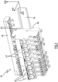
- FIG. 1 shows an electrical panel 10 according to the invention.
- the electrical panel 10 is configured to be integrated into an electrical installation, for example equipping a building.
- the electrical panel 10 is in the form of a modular row.
- this modular row can be associated with other modular rows.
- the electrical panel 10 accommodates several electrical protection devices.
- the electrical panel 10 is modular, that is to say that it is equipped with a variable number of electrical protection devices, depending on the needs of the electrical installation into which it is configured to be integrated, and that the Electrical protection devices can be of several types.
- electrical protection devices 12 of a first type and electrical protection devices 14 of a second type are shown.
- the electrical panel 10 further comprises a fixing rail 16, on which the electrical protection devices 12 and 14 are installed.
- the fixing rail 16 extends along an axis of width X10 of the electrical panel 10.
- the electrical protection devices 12 and 14 are juxtaposed along the axis of width X10.
- a depth axis Y10 and a height axis Z10 of the electrical panel 10 which are perpendicular to each other and to the width axis X10.
- the height axis Z10 is vertical and directed upwards.
- the electrical panel 10 further comprises a power comb 18, which extends along the axis of width X10, which is connected to all the electrical protection devices 12 and 14 and which supplies electrical energy to the electrical protection devices , via connectors 20.
- the connectors 20 are distributed into several groups, all the connectors of a group being electrically connected to each other and electrically isolated from the connectors of the other groups.
- the power comb 18 comprises four groups of connectors 20.
- three are each connected to a power supply phase of the electrical panel 10 and one is connected to a neutral conductor of the electrical panel.
- the power comb 18 comprises a different number of groups of connectors 20, for example two groups of connectors, respectively connected to a power phase and to a neutral conductor.
- the power comb 18 is arranged above the fixing rail 16, along the height axis Z10 of the electrical panel.
- the device 12 comprises a housing 30.
- a width direction X30, a depth direction Y30 and a height direction Z30 of the housing 30 are defined, which are perpendicular to each other and fixed relative to the housing 30.
- the housing 30 constitutes an essentially closed and electrically insulating envelope.
- the housing 30 advantageously comprises a front 32 and a back 34, distributed along the depth direction Y30, with the front 32 in the direction Y30 relative to the back 34.
- the device 12 is advantageously designed to be fixed on the fixing rail 16 via the housing 30.
- the device 12 advantageously comprises, on the back 34, any suitable fixing means, such as for example a latching clamp 36, by means of which the device 12 can be fixedly attached to the rail 16.
- any suitable fixing means such as for example a latching clamp 36, by means of which the device 12 can be fixedly attached to the rail 16.
- the back 34 of the housing 30 of the electrical protection device 12 is directed towards the rail 16 and the front 32 is opposite the rail 16.
- the housing 30 advantageously comprises a lower end 38 and an upper end 40 distributed in the direction Z30, with the upper end 40 in the direction Z30 relative to the lower end 38, the upper end 40 being arranged above the lower end 38 in the mounted configuration of the device 12 on the electrical panel 10.
- the housing 30 advantageously comprises a right flank 42 and a left flank 44, preferably plane and parallel, distributed in the direction X30, with the left flank 44 in the direction right side 42 in the mounted configuration of the device 12 on the electrical panel 10.
- the width of the device 12, measured in the direction X30 between the left side 44 and the right side 42, is between 15 mm and 25 mm, more preferably equal to 18 mm.
- the front 32 and the back 34 each connect the right side to the left side, in direction X30.
- Each side connects the back 34 to the facade 32, following direction Y30.
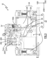
- the housing 30 comprises an internal partition 46 visible on the figures 3 to 10 , which extends parallel to the directions Y30 and Z30 and separates an internal volume of the housing 30 into a right compartment 48, visible on the figures 5 , 7 And 9 and in a left compartment 50, visible on the figures 3 , 4 , 6 , 8 And 10 .
- the right 48 and left 50 compartments are distributed in direction X30.
- the right compartment 48 is delimited by the partition 46 and the right side 42 in the direction X30, by the ends 38 and 40 in the direction Z30, and by the front 32 and the back 34 in the direction Y30.
- the left compartment 50 is delimited by the partition 46 and the left side 44 in the direction X30, by the ends 38 and 40 in the direction Z30, and by the front 32 and the back 34 in the direction Y30.
- the electrical protection device 12 is a bipolar device, in that it has two conduction paths.
- Each conduction path is expected to include an input terminal, an output terminal, a moving contact and a fixed contact.
- a first conduction path 60 comprises an input terminal 62, an output terminal 64, a movable contact 66 and a fixed contact 68, visible on the figures 3 , 6 And 8
- a second conduction path 70 comprises an input terminal 72, an output terminal 74, a movable contact 76 and a fixed contact 78, visible on the figures 5 , 7 And 9 .
- the conduction paths 60 and 70 are electrically isolated from each other.
- each conduction path is entirely arranged in one of the respective compartments 48 or 50 of the housing 30.
- the first conduction path 60 is arranged in the left compartment 50 and the second conduction path 70 is arranged in the right compartment 48.
- the internal partition 46 is interposed between the paths 60 and 70, so as to guarantee that they are electrically isolated from each other.
- the input terminals 62 and 72 are arranged at the upper end 40 of the housing 30, so that they can be electrically connected to the connectors 20 of the power comb 18 belonging to the electrical panel.
- the input terminal 62 is connected to a first connector 20 belonging to a first group of connectors of the power comb 18, while the input terminal 72 is connected to a second connector 20 belonging to a second group of connectors of the power comb 18.
- each input terminal 62 and 72 comprises a cavity 80, configured to accommodate a connector 20, and a screw 82, configured to tighten the connector 20 against the input terminal so as to establish electrical continuity between the connector and the input terminal.
- the device 12 is connected to the power comb 18 simply by plugging the connectors 20 of the comb into the input terminals 62 and 72 then tightening the screws 82.
- the input terminals 62 and 72, as well as the output terminals 64, 74, are screw terminals.
- the input terminals 62, 72 and/or the output terminals 64, 74 are automatic terminals, also called plug-in terminals, or quick connector terminals.
- Each conduction path constitutes a distinct pole of the device 12.
- the path 60 constitutes a neutral pole
- the path 70 constitutes a phase pole.
- path 60 is connected to a neutral conductor of the electrical panel via a connector 20 and path 70 is connected to a power supply phase of the electrical panel via a connector 20.
- each conduction path is designed to be brought to a distinct potential.
- the device 12 is designed to be used at low voltage, that is to say a voltage between 100V (Volts) and 600V, for example a voltage of 230V.
- the two conduction paths are phase conduction paths.
- the output terminals 64 and 74 are preferably arranged at the lower end 38 of the housing 30, so as to be able to be electrically connected to an electrical circuit supplying receiving loads, for example, in the case of a building, household appliances or lighting. These electrical loads are then powered with the electrical energy supplied to the input terminals 62 and 72 by the connectors 20 of the power comb 18, through the device 12.
- the input terminal 62 of the conduction path connected to a neutral conductor of the electrical panel is arranged at the lower end 38 of the housing 30, that is to say near the output terminals 64 and 74 , and the conduction path 60 forms a loop in the housing.
- three terminals are arranged at the lower end 38 of the housing and only the input terminal 72 is arranged at the upper end 40 of the housing.
- one of the three terminals is replaced by a plug-in clamp, or by an electric wire extending outside the housing 30.
- the fixed contact 68 is fixed relative to the housing 30, and is electrically connected to the input terminal 62.
- the movable contact 66 is electrically connected to the output terminal 64.
- the fixed contact 68 is arranged in the direction Z30 relative to mobile contact 66.
- the movable contact 66 preferably comprises a conductive end 90, ensuring the electrical contact function, and which is electrically connected to the output terminal 64.
- the movable contact 66 also comprises a contact carrier 92, which carries the end 90.
- the movable contact 66 is pivotable, relative to the housing 30, via the contact carrier 92, around a movable contact axis X66, parallel to the direction X30. This pivoting is carried out between a conduction position, shown on the figures 3 And 8 , and an isolation position, shown on the Figure 6 .
- the conductive end 90 is in electrical contact with the fixed contact 68, which electrically connects the input terminal 62 to the output terminal 64.
- the end 90 of the movable contact 66 is moved away from the fixed contact 68, so as to be electrically isolated from it, which breaks the electrical connection between terminals 62 and 64, so that terminals 62 and 64 are electrically isolated from each other.
- the fixed contact 78 is fixed relative to the housing 30, and is electrically connected to the input terminal 72.
- the movable contact 76 is electrically connected to the output terminal 74.
- the fixed contact 78 is arranged in the direction Z30 relative to mobile contact 76.
- the movable contact 76 preferably comprises a conductive end 94, ensuring the electrical contact function, and which is electrically connected to the output terminal 74.
- the movable contact 76 also comprises a contact carrier 96, which carries the end 94.
- the movable contact 76 is pivotable, relative to the housing 30, via the contact carrier 96, around a movable contact axis.
- the respective movable contact axes of the movable contacts 66 and 76 are combined, that is to say that the movable contact 76 pivots around the same axis as the movable contact 66, in other words around the X66 axis.
- the movable contact axes of the contacts 66 and 76 are parallel to each other, not merged, and both parallel to the direction X30.
- the pivoting of the contact 76 is carried out between a conduction position, shown on the figure 5 , and an isolation position, shown on the Figure 7 .
- the movable contacts 66 and 76 are advantageously pivotable relative to the housing independently. When they move from their respective conduction position to their respective isolation position, the movable contacts 66 and 76 advantageously rotate in the same direction around their respective movable contact axis, in the example around the axis X66. In particular, the contact ends 90 and 94 are then moved opposite the direction Z30, that is to say towards the output terminals 64 and 74, or towards the lower end 38 of the housing 30.
- the conductive end 94 is in electrical contact with the fixed contact 78, which electrically connects the input terminal 72 to the output terminal 74.
- the end 94 of the movable contact 76 is spaced from the fixed contact 78, so as to be electrically isolated therefrom, which breaks the electrical connection between terminals 72 and 74, so that terminals 72 and 74 are electrically isolated from one of them. 'other.
- the movable contact 76 is shown in the intermediate position, that is to say that the conductive end 94 is distant from the fixed contact 78 but the movable contact 76 is not in the isolation position. This position is obtained during the tilting of the mobile contact 76 from its conduction position to its isolation position.
- the electrical protection device 12 comprises a switching chamber 100, which is shown complete on the Figure 5 , and partially open on the figures 7 And 9 , to reveal its contents.
- the breaking chamber 100 aims to confer breaking power to the device 12, by dissipating any electric arc which could occur when the movable contact 76 passes from the conduction position to the isolation position, that is to say when it moves away from the fixed contact 78.
- the cutting chamber 100 is advantageously arranged in the right compartment 48, between the fixed contact 78 and the input terminal 72, along the back 34 of the housing 30.
- the cutting chamber 100 comprises for example a stack of metal plates 102, sometimes called fins or separators superimposed at a distance from each other, here in the direction Y30, to lengthen and thus extinguish the possible electric arc.
- the cutting chamber 100 advantageously comprises insulating cheeks, not shown, between which the plates 102 are arranged.
- the plates 102 are for example held between the internal partition 46 and the right side 42 of the housing 30.
- the input terminal 72 is interposed between the cutting chamber 100 and the upper end 40 of the housing.
- the fixed contact 78 is preferably extended by an arc horn 104, curved towards the stack of metal plates 102 of the cutting chamber 100.
- the cutting chamber advantageously comprises an arc horn 105, which is electrically connected to the conduction path 70, between the movable contact 76 and the output terminal 74.
- the arc horn 105 is arranged opposite the arc horn 105. arch 104.
- the possible electric arc is conducted to the metal plates 102 via the arc horns 104 and 105, to be divided and extinguished within the cutting chamber 100.
- the electrical protection device 12 further comprises three triggers 110, 112 and 114, each configured to be excited by an electrical fault of a distinct predetermined type and to switch the movable contacts 66 and 76 into the isolation position when they are excited.
- the 110 trigger visible on the figures 5 , 7 And 9 , is configured to be excited by an electrical fault of the short circuit type which is, for example, likely to occur between the conduction paths 60 and 70 or between the conduction path 70 and Earth.
- the trigger 110 is therefore in particular excited by a short circuit which would occur downstream of the output terminals 64 and 74, on the electrical circuit supplied through the device 12, or on one of its loads. In this case, it is a phase-neutral, or phase-earth, short circuit.
- the trigger 110 is placed in the right compartment 48, and connected in series on the conduction path 70.
- the trigger 110 is placed between the input terminal 72 and the fixed contact 78.
- the trigger 110 is arranged between the cutting chamber 100 and the facade 32 of the housing 30.
- the trigger 110 is arranged between the right side 42 of the housing and the internal partition 46 of the housing.
- the 110 trigger is sometimes called a magnetic trigger.
- the trigger 110 is in the form of a magnetic actuator, which here comprises an electromagnetic winding 120 and a movable core 122.
- the core 122 is visible only on the Figure 9 .
- the input terminal 72 is electrically connected to the fixed contact 78 via the trigger 110, in particular the electromagnetic winding 120.
- the intensity of the current circulating in the winding 120 suddenly becomes very high, so as to generate an electromagnetic force sufficient to move the mobile core 122 from a rest position, shown on the figures 5 And 7 , to a triggered position, shown on the Figure 9 , relative to the housing 30.
- the movement of the core 122 from the rest position to the triggered position is carried out in a direction opposite to the direction Z30, that is to say towards the lower end 38 of the housing.
- the core 122 When the core 122 is moved to the triggered position, it causes the rotation of the movable contacts 66 and 76 from their conduction position to their isolation position, thus interrupting the flow of an electric current between the input terminals 62 and 72 and output terminals 64 and 74.
- the electrical protection device 12 is shown in a configuration where the trigger 110 is being triggered, that is to say when the core 122 is in the triggered position.
- the movable contact 76 is no longer in the conduction position and has not yet reached the isolation position illustrated in Figure 7 and the mobile contact 66 has not yet left its conduction position.
- Trigger 112 visible on the figures 5 , 7 And 9 , is configured to be excited by an electrical fault of another predetermined type, namely an electrical fault of the overload type, which is, for example, likely to occur between the conduction paths 60 and 70.
- the trigger 112 is therefore in particular excited by an overload which would occur downstream of the output terminals 64 and 74, on the electrical circuit supplied through the device 12, or on one of its loads. This type of fault can occur when one or more loads connected to this electrical circuit impose too high a current demand.
- the trigger 112 is placed in the right compartment 48, and connected in series on the conduction path 70.
- the trigger 112 is placed between the output terminal 74 and the movable contact 76.
- the trigger 112 is placed between the back 34 and the front 32 of the housing 30.
- the trigger 112 is placed between the right side 42 of the housing and the internal partition 46 of the housing.
- the 112 trigger is sometimes called a thermal trigger.
- the trigger 112 is in the form of a thermal actuator, which is here formed by an electrically conductive and thermo-deformable bimetallic strip.
- the movable contact 76 is electrically connected to the output terminal 74 via the trigger 112, that is to say here via the bimetallic strip.
- a flexible braid 124 electrically connects the movable contact 76 to the trigger 112.
- the bimetallic strip When the bimetallic strip is in the deformed position, it causes the rotation of the movable contacts 66 and 76 from their conduction position to their isolation position, thus interrupting the circulation of an electric current between the input terminals 62 and 72 and the output terminals 64 and 74.
- the trigger 114 is configured to be excited by an electrical fault of another predetermined type, namely an electrical fault of the differential type, which is likely to occur between the conduction path 70 and the earth.
- the trigger 114 is therefore in particular excited by a current leak to earth, which would occur downstream of the output terminals 64 and 74, then causing a difference between the value of the intensity of the current circulating within the conduction path 70 and the value of the intensity of the current flowing in the opposite direction within the conduction path 60.
- the trigger 114 extends both in the compartments 48 and 50, crossing the internal partition 46. In the direction Z30, the trigger 114 is advantageously arranged between on the one hand, the output terminals 64 and 74, and on the other hand, the fixed contacts 68 and 78 and the mobile contacts 66 and 76.
- the 114 trigger is sometimes called a differential trigger.
- the trigger 114 comprises a differential sensor 126, which extends both in the compartments 48 and 50, being arranged along the back 34 of the housing 30.
- the trigger 114 also includes a relay 128, which extends only in the left compartment 50, being arranged between the facade 32 and the differential sensor 126.
- the differential sensor 126 comprises for example a ferromagnetic torus, carrying two electromagnetic windings, one formed by the conduction path 60 and the other formed by the conduction path 70.
- the electromagnetic winding of the conduction path 60 is advantageously formed by a part of the path 60 between the movable contact 66 and the output terminal 64.
- the electromagnetic winding of the path 70 is advantageously formed by a part of the path 70 which connects the movable contact 76 to the output terminal 74, more precisely by part of the path 70 between the trigger 112 and the output terminal 74.
- the movable contact 66 and the winding of the differential sensor 126 of the conduction path 60 are electrically connected using a braid, not shown.
- an electromagnetic field is generated at the level of the torus of the differential sensor 126.
- the relay 128 is configured to be activated when this threshold is exceeded, which has the effect of actuating the movement of a movable rod 130 belonging to the relay 128, from a rest position, shown on the figures 3 , 6 And 8 , up to a trigger position, not visible in the figures, relative to the housing 30.
- the movement of the movable rod 130 from the rest position to the triggered position is carried out in the direction Z30, it is that is to say towards the upper end 40 of the housing 30.
- the movable rod 130 Once the movable rod 130 has reached the triggered position, it should be brought back to the rest position to reset the relay 128 and thus allow the relay 128 again to activate the rod 130 in the event of a differential fault, as explained below.
- the movable rod 130 When the movable rod 130 is moved from its rest position to its triggered position, it causes the rotation of the movable contacts 66 and 76 from their conduction position to their isolation position, thus interrupting the circulation of an electric current between the input terminals 62 and 72 and output terminals 64 and 74.
- the electrical protection device 12 also includes a switching mechanism 150.
- the switching mechanism 150 is housed in the housing 30, partly in the compartment 48 and in the compartment 50.
- the switching mechanism 150 is configured to switch between an armed configuration, shown on the figures 3 to 5 And 10 , in which the mechanism 150 places the two movable contacts 66 and 76 in the conduction position, and a triggered configuration, shown on the figures 6 And 7 , in which the switching mechanism 150 places the movable contacts 66 and 76 in the isolation position.
- the switching mechanism 150 includes a bracket 152, visible on the figures 3 to 10 .
- the stirrup 152 pivots relative to the housing 30 around a stirrup axis X152, parallel to the movable contact axis X66.
- the stirrup extends into both compartments 48 and 50, being carried by the internal partition 46, astride it.
- the stirrup 152 is in a first orientation called “armed position” relative to the housing 30, around the axis X152.
- the stirrup 152 is in a second orientation called “triggered position”, around the axis X152.
- the mechanism 150 actuates the mobile contacts 66 and 76 via the bracket 152.
- the stirrup 152 comprises a plate 154, arranged in the left compartment 50, and a counter-plate 156, arranged in the right compartment 48.
- the plate 154 and the counter-plate 156 are arranged on either side and other of the internal partition 46 and are pivotable around the stirrup axis X152.
- the plate 154 and the counter-plate 156 are fixedly connected by a connecting shaft 158, so that any rotational movement of the plate 154 around the stirrup axis X152 results in an identical rotational movement of the counter-plate 156 around the caliper axis X152, and vice versa.
- the plate 154 of the stirrup 152 comprises for example a cam 160, arranged in the left compartment 50, via which the stirrup 152 drives the movable contact 66 of the first conduction path 60 from the conduction position to 'to the isolation position, when the stirrup 152 is pivoted from the armed position to the triggered position.
- the cam 160 comes to bear against the contact carrier 92 of the movable contact 66.
- the switching mechanism 150 advantageously comprises a spring 162, called a "contact spring”, which is arranged in the left compartment 50 while bearing both on the plate 154 of the stirrup 152 and on the movable contact 66, more precisely on the contact carrier 92.
- a contact spring which is arranged in the left compartment 50 while bearing both on the plate 154 of the stirrup 152 and on the movable contact 66, more precisely on the contact carrier 92.
- the spring 162 applies a force on the contact 66, bearing on the plate 154, preferably on the cam 160, which tends to press the movable contact 66 against the fixed contact 68, when the stirrup 152 is in armed position. This effort ensures a satisfactory contact pressure between the movable contact 66 and the fixed contact 68.
- the counter-plate 156 of the stirrup 152 comprises for example a cam 164, disposed in the right compartment 48, via which the stirrup 152 drives the movable contact 76 of the second conduction path 70 from the position of conduction to the isolation position, when the stirrup 152 is pivoted from the armed position to the triggered position.
- the cam 164 comes to bear against the contact carrier 96 of the movable contact 76.
- the switching mechanism 150 advantageously comprises a spring 166, called a "contact spring”, which is arranged in the right compartment 48 while bearing both on the counter-plate 156 of the stirrup 152 and on the movable contact 76, more precisely on the contact carrier 96.
- a contact spring which is arranged in the right compartment 48 while bearing both on the counter-plate 156 of the stirrup 152 and on the movable contact 76, more precisely on the contact carrier 96.
- the contact spring 166 applies a force on the contact 76, by bearing on the counter-plate 156, preferably on the cam 164, which tends to press the movable contact 76 against the fixed contact 78, when the stirrup 152 is in the armed position. This effort ensures a satisfactory contact pressure between the movable contact 76 and the fixed contact 78.
- the contact springs 162 and 166 are torsion springs, mounted respectively on the movable contact 66 and on the movable contact 76 and of which a first branch bears respectively on the movable contact 66 and on the movable contact 76 and of which a second branch respectively bears on cam 160 and cam 164.
- the cams 160 and 164 and that the contact springs 162 and 166 transmit a rotational movement of the stirrup 152 into a rotational movement of the movable contacts 66 and 76, and that the direction of rotation of the movable contacts 66 and 76 is opposite the direction of rotation of the stirrup 152.
- the stirrup switches from the armed position to the triggered position, it rotates clockwise, under the angle of the figures 3 And 4 , and rotates the movable contacts 66 and 76 in the counterclockwise direction, under the angle of the figures 3 And 4 .
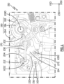
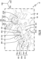
- the switching mechanism 150 further comprises a spring 170, called a “caliper spring”, visible on the figures 3 , 4 , 6 , 8 , 10 , 11 And 12 and shown alone with deck 154 figures 11 And 12 .
- the stirrup spring 170 is here arranged in the left compartment 50 of the housing 30.
- the stirrup spring 170 applies a force to the plate 154 of the stirrup 152, bearing on the housing 30, which tends to move the stirrup 152 from the armed position to the triggered position.
- the stirrup spring 170 is a torsion spring, mounted on the internal partition 46, a first branch 172 of which bears against the housing 30 and a second branch 174 of which bears against a stop 176 of the platinum 154.
- the first branch 172 exerts a force F on the housing 30 and the second branch 174 exerts a force on the stop 176 of the plate.
- the force F exerted by the stirrup spring 170 on the stop 176 generates a moment M on the plate 154 which causes its rotation around the stirrup axis X152 by a lever arm phenomenon.
- the force F exerted by the second branch 174 on the stop 176 is directed along a straight line, denoted D176, which is perpendicular to the contact surface between the second branch and the stop and which is located in a plane perpendicular to direction X152.
- the intensity of the moment M generated by the stirrup spring 170 on the plate 154 depends on the one hand on the intensity of the force F exerted by the second branch 174 on the stop 176 and on the other hand on the distance between the caliper axis X152 and the straight line D176, denoted D and measured along an axis perpendicular to the straight line D176 and passing through the caliper axis X152. Indeed, the greater this distance D, the greater the lever arm generating the moment M from the force F, because the moment M is equal to the product of the force F by the distance D.
- the stirrup 152 is configured so that, when the stirrup 152 is pivoted from the armed position to the triggered position, the distance D increases, that is to say the intensity of the moment M increases.
- the increase in the moment M causing the pivoting of the stirrup 152 is advantageous, because it makes it possible to increase the tilting speed of the mobile contacts 66 and 76 between their conduction position and their isolation position.
- the electrical protection device 12 also includes a switching lever 190.
- the switching lever 190 is pivotable, relative to the housing 30, around a lever axis X190, parallel to the axis X30, between a closed position, shown on the figures 3 to 5 And 8 to 10 , and an opening position, shown on the figures 6 And 7 .
- the switching lever 190 here comprises a base 192, via which the lever is pivotally attached to the housing 30.
- the base 192 is arranged through an opening belonging to the facade 32, closing this opening.
- the switching lever 190 is carried by the facade 32.
- the base 192 extends advantageously on either side of the internal partition 46.
- the lever 190 is advantageously centered in the direction To be accessible by the user, the crank pin 194 is placed outside the housing 30.
- the switching mechanism 150 advantageously comprises a spring 196, called a “lever spring”, visible on the figures 3 , 4 , 6 , 8 And 10 .
- the lever spring 196 applies a force to the lever 190 by bearing on the housing 30, which tends to bring the lever from the closed position to the open position.
- the lever spring 196 is a torsion spring, housed inside the base 192 around the lever axis internal partition 46.
- the switching mechanism 150 advantageously comprises a connecting rod 200, visible on the figures 3 , 4 , 6 , 8 And 10 .
- the connecting rod 200 is for example arranged in the left compartment 50.
- the connecting rod 200 comprises a first end 202 attached to the lever 190, in particular to the base 192. Via this first end 202, the connecting rod 200 can pivot relative to the joystick 190, around an axis which is parallel and not coincident with the joystick axis X190. Thus, the rotation of the lever 190 is linked to a crank movement of the first end 202 of the connecting rod 200.
- the first end 202 of the connecting rod 200 describes an arc of a circle centered on the lever axis X190.
- the connecting rod 200 comprises a second end 204, opposite the first end 202, which interacts in particular with the stirrup 152, as described below.
- the second end 204 is guided in a groove 206 formed in the plate 154, that is to say in a plane parallel to the directions Y30 and Z30.
- the switching mechanism 150 advantageously comprises a locking latch 210, visible on the figures 3 , 4 , 6 , 8 And 10 . At least part of the locking latch 210 is arranged in the same compartment as that of the connecting rod 200, to cooperate with the latter, here the left compartment 50.
- At least part of the locking latch 210 extends into the compartment(s) where the triggers 110, 112 and 114 are housed, to cooperate mechanically with the latter, here the compartments 48 and 50.
- the latch 210 is advantageously carried by the stirrup 152. Latch 210 moves between a locking configuration, shown on the figures 3 to 5 And 10 , and an unlock configuration, shown on the figures 6 to 9 .
- each trigger 110, 112 and 114 is configured to switch the locking latch 210 from the locking configuration to the unlocking configuration, directly or indirectly, when said trigger 110, 112 or 114 concerned detects an electrical fault, of the type predetermined for this trigger.
- the latch 210 comprises a lock 212 and a hook 214 which cooperate together.
- the hook 214 extends into both compartments 48 and 50, so as to be visible on the figures 3 to 10 . In practice, it is expected that the hook 214 extends both into the compartment(s) receiving the triggers to be actuated by the latter. The hook 214 also extends into the compartment where the lock 212 is located, to cooperate with the latter.
- the hook 214 is carried by the stirrup 152, being pivotable relative to the stirrup 152 around an axis X214, called “hook axis", here parallel and not confused with the stirrup axis X152. This pivoting is carried out when the latch 210 moves between the locking and unlocking configurations.
- the hook 214 comprises a first part 216, disposed in the same compartment as the lock 212, and a second part 218, disposed in the other compartment.
- the first part 216 and second part 218 are fixedly connected to each other, preferably by being embedded in one another, so that any movement of the first part 216 results in an identical movement of the second part 218, and vice versa.
- the lock 212 extends into the left compartment 50, so as to be visible on the figures 3 , 4 , 6 , 8 And 10 . In practice, it is expected that the lock 212 extends in the same compartment as that of the connecting rod 200, to cooperate with the latter.
- the lock 212 is carried by the stirrup 152, being pivotable relative to the stirrup 152 around an axis X212, called "lock axis", here parallel and not confused with the axis X152.
- the lock pin X212 is carried by the connecting shaft 158 which connects the plate 154 to the counter-plate 156.
- a through hole 213 is provided in the lock 212.
- the hook 214 In the locking configuration, the hook 214 is in an orientation called “holding orientation”, where the hook 214 holds the lock 212 in an orientation called “capture orientation”.
- the first part 216 of the hook 214 comprises for example a radial arm 220, against which the lock 212 comes into rotational abutment.
- the hook 214 In the unlocking configuration, the hook 214 is in an orientation called “unhooking orientation", where the hook 214 allows the lock 212 to be pivoted relative to the stirrup 152.
- the hook 214 pivots clockwise to move from the holding orientation to the unhooking orientation. When the hook 214 is moved from the release orientation to the hold orientation, it returns and holds the latch 212 in the capture orientation.
- the hook 214 and the lock 212 are in contact, so that the lock 212 is prevented from rotating around the lock axis X212 by the hook 214, whereas in the unlocking configuration, the hook 214 and the lock 212 are not in contact, so that the lock 212 is not prevented from pivoting around the lock axis X212 by the hook 214
- the switching mechanism 150 advantageously comprises a spring 222, called a “latch spring”, visible on the figures 5 , 7 And 9 .
- the latch spring 222 is provided in the right compartment 48.
- the spring 222 applies a force on the locking latch 210, bearing on the counter-plate 156 of the stirrup 152, which tends to bring back the latch lock 210 from the unlock configuration to the lock configuration.
- the spring 222 is a torsion spring, one branch of which rests on the counter-plate 156 and another branch of which rests on the second part 218 of the hook 214, so that the spring 222 actuates the latch 210 by via the hook 214.
- the latch spring 222 tends to bring the hook 214 back from the unhooking orientation towards the holding orientation.
- the second end 204 of the connecting rod 200 is captured by the locking latch 210, in particular by the latch 212, when the latch 210 is in the configuration of locking, here when the lock 212 is in the capture orientation. Indeed, the second end 204 of the connecting rod is disposed in the through hole 213 of the lock 212. Then, via the latch 210, the second end 204 is attached to the stirrup 152 by being pivotable relative to said stirrup 152 .
- the second end 204 of the connecting rod 200 is clamped between the walls of the groove 206 of the plate 154 and the walls of the through hole 213 of the lock 212 and cannot then be seated. move relative to the plate 154 of the stirrup 152 nor relative to the lock 212.
- the second end 204 of the connecting rod 200 is free to move in the groove 206 of the plate 154, and this movement causes a rotation of the lock 212 around the lock axis X212.
- the position of the switching lever 190 is subject to the position of the stirrup 152, and therefore to the position of the movable contacts 66 and 76, via the connecting rod 200 and the latch locking 210.
- the bracket 152 is placed in the armed position, via the connecting rod 200, the second end of which 204 is captured by the latch 210 to drive the stirrup 152.
- the stirrup 152 being placed in the armed position, it places the movable contacts 66 and 76 in the conduction position, via the contact springs 162 and 166.
- the bracket 152 In the locking configuration of the latch 210, when the switching lever 190 is placed in the open position by a user, the bracket 152 is placed in the triggered position, via the connecting rod 200, the second end of which 204 is captured by the locking latch 210 to drive the stirrup 152.
- the stirrup being placed in the triggered position, it places the contacts 66 and 76 in the isolation position, via the cams 160 and 164 of the plate 154 and counterplate 156.
- the yoke 152 When the locking latch 210 is in the locked configuration, the yoke 152 is in the armed position and the switch handle 190 is in the closed position, the yoke 152 and the switch handle 190 hold each other in position, at against the stirrup spring 170, tending to move the stirrup 152 towards the triggered position, and the lever spring 196, tending to move the switching lever 190 towards the open position.
- the connecting rod 200 is in the locking orientation when the first end 202 is positioned in a direction opposite to the direction Y30 relative to a straight line, parallel to the directions Y30 and Z30 and crossing the lever axis X190 and the second end 204.
- the rotation of the switching lever 190 from the closed position to the open position causes a movement of the first end 202, in a plane parallel to the directions Y30 and Z30, which describes an arc of circle centered on the X190 controller axle.
- This arcuate movement leads to a movement of the first end 202 in the direction opposite to the direction Z30, that is to say towards the lower end 38 of the housing, as long as the connecting rod 200 is in the orientation locking, then to a movement of the first end 202 in the direction Z30 when the connecting rod 200 is no longer in the locking orientation, that is to say when the first end is positioned in the direction Y30 relative to a right, parallel to the directions Y30 and Z30 and crossing the lever axis X190 and the second end 204.
- the movement of the first end 202 in the direction opposite to the direction Z30 causes a movement of the second end 204 in the same direction.
- the second end 204 exerts a force on the walls of the groove 206 of the plate 154 as well as a force on the walls of the through hole 213 of the lock 212.
- This force on the lock 212 tends to make the lock 212 rotate around of the lock pin X212 clockwise, at the angle of the figures 3 And 4 , which tends to maintain the locking latch 210 in the locking configuration.
- the connecting rod 200 maintains the locking latch 210 in the locking configuration.
- the lock 212 and the stirrup 152 are then prevented from rotating, which prevents the movement of the second end 204 in the direction opposite to the direction Z30 and which prevents the movement of the first end 202.
- the switch handle 190 is prevented from rotating.
- the yoke 152 is prevented from rotating.
- the switching lever 190 and the yoke 152 hold each other in the closed position and in the armed position, via of the connecting rod 200.
- the connecting rod 200 is moved from its locking orientation until the first end 202 is positioned in the direction Y30 relative to the right, parallel to the directions Y30 and Z30, which passes through the lever axle X190 and the second end 204.
- the locking latch releases the bracket 152 so that the bracket tilts towards the triggered position.
- the handle 190 places the switch mechanism 150 in the armed configuration.
- the lever 190 places the switching mechanism 150 in the triggered configuration.
- the direction of rotation of the switching lever 190 is identical to the direction of rotation of the bracket 152.
- the switching lever 190 is actuated towards the open position, that is to say -say that the joystick rotates around the X190 joystick axis clockwise, at the angle of the figures 3 And 4 , then the caliper is tilted to the triggered position by rotating around the caliper axis X152 clockwise, under the angle of the figures 3 And 4 .
- Each trigger 110, 112 and 114 is individually configured to trigger a triggered configuration of the switching mechanism 150, while the switching mechanism 150 was in armed configuration, when said trigger 110, 112 or 114 is excited by the electrical fault of the predetermined type for this trigger 110, 112 or 114. This leads to the moving contacts 66 and 76 being placed in the isolation position by the switching mechanism 150, when the electrical fault occurs.
- each trigger 110, 112 and 114 is designed to trigger a tilting of the locking latch 210 from the locking configuration to the unlocking configuration.
- the groove 206 of the plate 154 forms a circular path along which the second end 204 of the connecting rod 200 is allowed to move.
- the connecting rod 200 no longer operates a mutual holding in position of the stirrup 152 and the switching lever 190. Then, the lever 190 is returned to the position opening under the action of the lever spring 196 and the stirrup 152 is returned to the triggered position under the action of the stirrup spring 170, the stirrup 152 then driving the movable contacts 66 and 76 towards the position d 'isolation.
- the switching mechanism 150 in particular the lever spring 196, returns the switching lever 190 to the open position when the switching mechanism 150 is placed in the triggered configuration, whether by action of the user on the switching lever 190 itself, or under the action of a trigger operated by one of the triggers 110, 112 or 114.
- the magnetic trigger 110 actuates for example a rocker 240 belonging to the switching mechanism 150, the rocker 240 driving the hook 214 to the unhooked position .
- the rocker 240 is visible on the figures 5 , 7 And 9 .
- the rocker 240 is attached to the housing 30, for example to the internal partition 46, by being pivotable relative to the housing 30 around a rocker axis X240 parallel to the stirrup axis X152, between an initial position shown on the figures 5 And 7 , and a tilting position shown on the Figure 9 .
- the magnetic trigger 110 drives the rocker 240 from the initial position to the tilting position by moving the mobile core 122, which comes to bear against a first end 242 of the rocker 240, here in a direction opposite to the direction Z30.
- the rocker 240 has a second end 244, which bears against a leg 246 belonging to the second part 218 of the hook 214, in the direction Z30, so that the hook 214 pivots to the unhooking orientation under the action of the pivoting of the rocker 240 to the tilting position, against the force of the latch spring 222.
- the mobile core 122 returns to its initial position, and authorizes the rocker 240 to be returned to the initial position, the rocker 240 thus authorizing the hook 214 to be returned to the holding orientation.
- the rocker 240 is then returned to the initial position via the leg 246 of the second part 218 of the hook 214, while the hook 214 is itself returned into the holding orientation by the latch spring 222.
- the mobile core 122 when the mobile core 122 is moved from its rest position to its triggered position, it also impacts the contact carrier 96 of the movable contact 76.
- the movable contact 76 is directly moved to the isolation position, without waiting for the pivoting of the stirrup 152.
- the tilting of the movable contact 76 in the isolated position is faster than the tilting of the locking latch 210 in the unlocked position and than the tilting of the stirrup 152 in the triggered position, so that, when the stirrup tilts in the triggered position, it drives only the tilting of the movable contact 66 in the isolation position and also makes it possible to maintain the movable contact 76 in the isolation position, due to the action of the cam 164.
- the thermal trigger 112 also activates the rocker 240 from the initial position to the rocker position, here by means of a link 250, belonging to the switching mechanism 150.
- the link 250 comprises a first end fixed to the bimetal forming the trigger 112 and guided in translation in a pocket 252 formed in the internal partition 46 of the housing 30 and a second end fixed to the first end 242 of the rocker 240
- the deformation of the bimetallic strip under the effect of an electrical fault leads to moving the link 250 in a direction opposite to the direction Z30, so that the rocker 240 is driven from the initial position to the tilting position, as when the mobile core 122 of the magnetic trigger 120 comes to rest on the first end 242 of the rocker 240.
- the differential trigger 114 actuates for example a mechanical force amplifier 260, which is visible on the figures 3 , 4 , 6 And 8 , via the movable rod 130.
- the amplifier 260 includes for example a drawer 262, a lock 264, a drawer spring 266, a lock spring 268 and a reset lever 270.
- the drawer 262 slides relative to the housing 30 between an armed position, where the drawer 262 allows the locking latch 210 to be in the locking configuration, and a triggered position, where the drawer 262 places the latch 210 in the unlocking configuration.
- the drawer 262 comes for example to bear against a leg 272 belonging to the first part 216 of the hook 214, when the drawer 262 is moved from the position armed to the triggered position, which drives the hook 214 from the holding orientation to the unhooking orientation.
- the drawer spring 266 applies a force to the drawer 262, which tends to move the drawer from the armed position to the tripped position.
- the movable contact 66 passes from the conduction position to the isolation position, the movable contact 66 brings the drawer 262 back to the armed position, against the force of the drawer spring 266, by coming into rest against drawer 262.
- the lock 264 is carried by the internal partition 46.
- the lock 264 is pivotable between a locking position, shown on the figures 3 , 4 , 6 And 8 , where the lock 264 maintains the drawer 262 in the armed position, against the action of the drawer spring 266, and an unlocking position, not visible in the figures, where the lock 264 authorizes the drawer 262 to be moved from the position armed to the position triggered by the drawer spring 266, and to be returned from the triggered position to the armed position by the movable contact 66.
- the lock spring 268 exerts a force on the lock 264, bearing on the internal partition 46 of the housing 30, which tends to bring the lock 264 from the unlocking position to the locking position.
- the reset stand 270 is carried by the housing 30, in particular by the internal partition 46, and extends between the lock 264 and the movable rod 130 of the trigger 114.
- the movable rod 130 When a differential fault occurs, the movable rod 130 is moved, here in the direction Z30. Under the action of the movement of the movable rod 130, the reset stand 270 is pivoted between a first position, shown on the figures 3 , 4 , 6 And 8 , and a second position, not visible in the figures. In this pivoting, the crutch 270 drives the lock 264 from its locking position to the unlocking position, against the action of the lock spring 268. The lock 264 being in the unlocking position, the drawer 262 is authorized to be moved from the armed position to the triggered position, under the action of the drawer spring 266, and presses on the leg 272 of the hook 214, which causes the hook 214 to pivot from the holding orientation to the stall orientation.
- the drawer 262 switches the locking latch 210 from the locking configuration to the unlocking configuration.
- the stirrup 152 tilts the movable contacts 66 and 76 from the conduction position to the isolation position, by tilting itself from the armed position to the triggered position.
- the contact 66 comes to bear against the drawer 262 so as to bring the drawer 262 back towards the armed position, against the action of the drawer spring 266.
- the drawer 262 drives the reset lever 270 to the first position.
- the movable rod 130 is brought back by the stand 270 to its initial position, so that the differential trigger 114 is reset.
- the drawer 262 During the movement of the drawer 262 towards the armed position, the drawer 262 allows the lock 264 to be returned to the position locking by the lock spring 268, so that the lock 264 maintains the drawer 262 in the armed position.
- the mechanical amplifier 260 and the differential trigger 114 have returned to their original configuration, to allow new triggering if a new fault occurs.
- the yoke 152 is in the triggered position, the movable contacts 66 and 76 are in the isolation position and the switching lever 190 is in the open position.
- the switching mechanism 150 described here and its mode of triggering by the triggers 110, 112 and 114 is given only by way of illustrative example.
- the magnetic trigger 110 and the thermal trigger 112 can be considered as a single trigger, then called “magnetothermal trigger", which switches the switching mechanism 150 into the triggered configuration when an electrical fault such as short circuit or overload of produced, by acting on the rocker 240.
- the stirrup 152 rotates in a direction opposite to the movable contacts 66 and 76 makes it possible to position the magnetic trigger 110 in the upper part of the housing 30, in practice as close as possible to the upper end 40 of the housing.
- the positioning of the magnetic trigger is constrained by the direction of rotation of the movable contact 76, because the exit direction of the movable core 122 of the magnetic trigger must correspond to the direction of movement of the movable contact 76, the movable contact being driven by the mobile core 122 when the magnetic trigger 110 is excited by an electrical fault.
- the internal distribution of the elements included in the electrical protection device 12 is summarized as follows:
- the input terminals 62, 72 are arranged in the direction Z30 relative to the output terminals 64, 74, that is to say above the output terminals 64, 74, and closest to the comb.
- power supply 18 in mounted configuration of the device on the electrical panel 10.
- the fixed contacts 68, 78 are arranged, in the height direction Z30, between the output terminals 64, 74 and the input terminals 62, 72.
- the movable contacts 66, 76 are arranged, in the height direction Z30, between the fixed contacts 68, 78 and the input terminals 62, 72.
- the switching mechanism 150 is arranged, in the height direction Z30, between the output terminals 64, 74 and the input terminals 62, 72 and, in the depth direction Y30, between the back 34 and the front 32 of the housing 30.
- the switching mechanism is arranged partially in the two compartments 48 and 50, on either side of the internal partition 46.
- the switching lever 190 is arranged, in the depth direction Y30, between the switching mechanism 150 and the facade 32.
- the magnetic trigger 110 is arranged, in the height direction Z30, between the movable contacts 66, 76 and the input terminals 62, 72, in the depth direction Y30, between the back 34 and the switching mechanism 150, and in the width direction X30, between the right side 42 and the internal partition 46 of the housing 30, that is to say in the right compartment 48.
- the cutting chamber 100 is arranged, in the height direction Z30, between the movable contacts 66, 76 and the input terminals 62, 72, in the depth direction Y30, between the back 34 and the magnetic trigger 110 , and in the width direction at the same level according to height direction Z30 and in the same compartment.
- the thermal trigger 112 is arranged, in the height direction Z30, between the output terminals 64, 74 and the movable contacts 66, 76, in the depth direction Y30, between the back 34 of the housing 30 and the release mechanism. switching 150, and in the width direction as the cutting chamber 100 and as the magnetic trigger 110.
- the differential trigger 114 is arranged, in the height direction Z30, between the output terminals 64, 74 and the thermal trigger 112, and, in the depth direction Y30, between the back 34 and the front 32. According to the direction of width entirely arranged in the left compartment 50 and the differential sensor 126 is arranged in the two compartments, in an opening made in the internal partition 46.
- the facade 32 of the housing 30 comprises a central part 280, which is more advanced, in the direction Y30, than an upper part 282 and a lower part 284, located respectively, in the direction Z30, above and below the central part 280.
- This advancement of the central part 280 defines an advancement volume 286.
- the advance volume 286 includes only the switching lever 190 and part of the switching mechanism 150.
- the volume advance 286 includes in particular the stirrup 152 and the locking latch 210.
- the triggers 110, 112 and 114 are arranged, in the depth direction Y30, between on the one hand the back 34 of the housing and on the other share the upper part 282, the lower part 284 and the advance volume 286.
- the movable contacts 66 and 76 extend from the advance volume 286, where the movable contact axis X66 is located, in direction of the back 34, in a direction opposite to the direction Y30.
- the differential trigger 114 constitutes, for the electrical protection device 12, a functional component which is replaceable by another functional component offering a different function.
- a functional component which is in the example shown the differential trigger 114
- a main module denoted 300, which advantageously comprises, in the In the example shown, the conduction paths 60 and 70, the cutting chamber 100, the magnetic trigger 110, the thermal trigger 112, the switching mechanism 150 and the switching handle 190.
- the trigger 114 is replaced by another functional component which is a trigger configured to be excited by an electrical fault of a predetermined type other than the aforementioned electrical faults, such as for example an electric arc occurring on a connected installation at output terminals 64 and 74, or a trigger configured to be controlled by a communication system, for example to be triggered when an opening signal is communicated.
- a trigger configured to be excited by an electrical fault of a predetermined type other than the aforementioned electrical faults, such as for example an electric arc occurring on a connected installation at output terminals 64 and 74, or a trigger configured to be controlled by a communication system, for example to be triggered when an opening signal is communicated.
- the trigger 114 is replaced by another functional component which is a monitoring system.
- a monitoring system is in practice a monitoring system configured to measure physical quantities representative of the operation of the protection device and/or to detect the operating state of the protection device.
- a monitoring system is configured to communicate information with a remote information system.
- a monitoring system makes it possible to count the number of times the bracket 152 is tilted from the armed position to the triggered position, or to monitor the consumption of an installation connected to the output terminals 64 and 74.
- the switching mechanism 150 does not include a mechanical force amplifier 260.
Landscapes
- Engineering & Computer Science (AREA)
- Power Engineering (AREA)
- Switch Cases, Indication, And Locking (AREA)
- Breakers (AREA)
- Patch Boards (AREA)
- Emergency Protection Circuit Devices (AREA)
- Gas-Insulated Switchgears (AREA)
Claims (10)
- Elektrische Schutzvorrichtung (12), umfassend:- ein Gehäuse (30), mittels dessen die elektrische Schutzvorrichtung konfiguriert ist, um auf einer Schiene (16) montiert zu werden, die zu einer elektrischen Schalttafel (10) gehört,- zwei Leitungspfade (60, 70), die elektrisch voneinander isoliert und über die Breite (X30) des Gehäuses verteilt sind, wobei jeder Leitungspfad einzeln Folgendes umfasst:o einen Eingangsanschluss (62, 72), der an einem oberen Ende (40) des Gehäuses angeordnet ist, um mit einem Stromversorgungskamm (18) verbunden zu werden, der zu der elektrischen Schalttafel gehört;o eine Ausgangsanschluss (64, 74), der an einem unteren Ende (38) des Gehäuses angeordnet ist; undo einen beweglichen Kontakt (66, 76), der in Bezug auf das Gehäuse zwischen einer leitenden Position, in der der bewegliche Kontakt den Eingangsanschluss mit dem Ausgangsanschluss dieses Leitungspfads elektrisch verbindet, und einer isolierenden Position, in der der Eingangsanschluss und der Ausgangsanschluss des Leitungspfads elektrisch voneinander isoliert sind, drehbar ist,- einen Schaltmechanismus (150), der konfiguriert ist, um zwischen einer gespannten Konfiguration, in der der Schaltmechanismus die beweglichen Kontakte in eine leitende Position bringt, und einer ausgelösten Konfiguration, in der der Mechanismus die beweglichen Kontakte in eine isolierte Position bringt, umzuschalten,- einen ersten Auslöser (110, 112), der in dem Gehäuse angeordnet und konfiguriert ist, um den Schaltmechanismus unter dem Einfluss eines elektrischen Fehlers einer ersten Art in die ausgelöste Konfiguration umzuschalten,- einen Schaltgriff (190):o der um eine Griffachse (X190) drehbar ist;o der von einem Benutzer zwischen einer Schließposition, um den Schaltmechanismus in eine gespannte Position zu bringen, und einer offenen Position, um den Schaltmechanismus in eine ausgelöste Konfiguration zu bringen, betätigt werden kann; undo der durch den Schaltmechanismus von seiner Schließstellung in seine Öffnungsstellung betätigt werden kann, wenn der Schaltmechanismus unter der Wirkung des ersten Auslösers in die ausgelöste Konfiguration geschwenkt wird,wobei jeder bewegliche Kontakt (66, 76) in Bezug auf das Gehäuse (30) um eine bewegliche Kontaktachse (X66) parallel zu der Griffachse (X190) drehbar ist, wobei, wenn der Schaltgriff (190) von der Schließposition in die Öffnungsposition geschwenkt wird und die beweglichen Kontakte von ihrer leitenden Position in ihre isolierende Position geschwenkt werden, die beweglichen Kontakte in Bezug auf das Gehäuse um ihre jeweilige bewegliche Kontaktachse in die gleiche Richtung drehen und die Drehrichtung der beweglichen Kontakte der Drehrichtung des Schaltgriffs entgegengesetzt ist,wobei der Schaltmechanismus (150) einen Bügel (152) umfasst, der um eine Bügelachse (X152) parallel zu der beweglichen Kontaktachse (X66) zwischen einer gespannten Position, wenn der Schaltmechanismus in einer gespannten Konfiguration ist, und einer ausgelösten Position, wenn der Schaltmechanismus in einer ausgelösten Konfiguration ist, drehbar ist, wobei der Bügel zu Folgendem konfiguriert ist:- wenn der Bügel in die gespannte Position gebracht wird, Bringen der beweglichen Kontakte (66, 76) in die leitende Position; und- wenn der Bügel in die ausgelöste Position gebracht wird, Bringen der beweglichen Kontakte in die isolierte Position,der Schaltmechanismus (150) ferner umfassend:eine Bügelfeder (170), die eine Kraft auf den Bügel (152) in Bezug auf das Gehäuse (30) ausübt, die dazu neigt, den Bügel aus seiner gespannten Position in seine ausgelöste Position zu schwenken, undeine Sperrklinke (210), die beweglich ist zwischen:o einer Verriegelungskonfiguration, wobei:▪ die Sperrklinke die Drehung des Bügels an die Drehung des Schaltgriffs (190) koppelt, sodass der Griff den Bügel in die gespannte Position antreibt, wenn der Griff in Richtung der Schließposition betätigt wird, und der Griff das Schwenken des Bügels in die ausgelöste Position freigibt, wenn der Griff in Richtung der Öffnungsposition betätigt wird,▪ wenn der Bügel in der gespannten Position ist und der Schaltgriff in der Schließposition ist, sich der Bügel und der Schaltgriff gegenseitig in Position halten; undo eine Entriegelungskonfiguration, wobei:▪ die Sperrklinke das Schwenken des Bügels in die ausgelöste Position zulässt, selbst wenn der Griff in der Schließposition ist,▪ die Sperrklinke die Drehung des Schaltgriffs in seine Öffnungsposition zulässt, wenn der Schaltmechanismus in die ausgelöste Konfiguration schwenkt,dadurch gekennzeichnet, dass der Bügel und die beweglichen Kontakte in entgegengesetzter Richtung schwenken, wenn der Bügel von seiner gespannten Position in seine ausgelöste Position geschwenkt wird und die beweglichen Kontakte von ihrer leitenden Position in ihre isolierende Position geschwenkt werden.
- Elektrische Schutzvorrichtung (12) nach Anspruch 1, wobei:- der Schaltgriff (190) ferner eine Grifffeder (196) umfasst, die eine Kraft auf den Schaltgriff in Bezug auf das Gehäuse (30) ausübt, die dazu neigt, den Griff aus der Schließposition in die Öffnungsposition zu schwenken,- der Schaltmechanismus ferner eine Schaltstange (200) umfasst, umfassend ein erstes Ende (202), das mit dem Griff verbunden ist, und ein zweites Ende (204), das:o von der Sperrklinke (210) erfasst wird, wenn die Sperrklinke in der Sperrkonfiguration ist, sodass:▪ wenn der Schaltgriff in der Schließposition ist, die Schaltstange die Sperrklinke in der Verriegelungskonfiguration und den Schaltgriff in der Schließposition hält, indem sie sich mit ihrem ersten Ende an dem Griff und mit ihrem zweiten Ende an dem Bügel (152) und der Sperrklinke abstützt,▪ wenn der Schaltgriff von seiner Schließstellung in seine Öffnungsstellung betätigt wird, treibt der Griff die Sperrklinke über die Schaltstange in die Entriegelungskonfiguration an, undo von der Sperrklinke freigegeben wird, wenn die Sperrklinke in der entriegelten Konfiguration ist, sodass die Schaltstange dem Schwenken des Griffs in die Öffnungsposition und des Bügels in die ausgelöste Konfiguration nicht entgegenwirkt.
- Elektrische Schutzvorrichtung (12) nach einem der vorherigen Ansprüche, wobei die Sperrklinke (210) Folgendes umfasst:- einen Haken (214), der in Bezug auf den Bügel (152) um eine Hakenachse (X214) parallel zu der Bügelachse (X152) schwenkbar ist, und- einen Riegel (212), der in Bezug auf den Bügel um eine Riegelachse (X212) parallel zu der Bügelachse schwenkbar ist,und wobei:- der Riegel und der Haken in der verriegelten Konfiguration miteinander in Kontakt sind, um die Drehung des Bügels an die Drehung des Schaltgriffs (190) zu koppeln, und- sich der Riegel und der Haken in der entriegelten Konfiguration nicht berühren, um die Drehung des Bügels gegenüber der Drehung des Griffs freizugeben.
- Elektrische Schutzvorrichtung (12) nach einem der vorherigen Ansprüche, wobei der Schaltmechanismus (150) ferner eine Klinkenfeder (222) umfasst, die eine Kraft auf die Sperrklinke (210) in Bezug auf den Bügel (152) ausübt, die dazu neigt, die Klinke in die verriegelte Konfiguration zu schwenken.
- Elektrische Schutzvorrichtung (12) nach einem der vorherigen Ansprüche, wobei:- die Bügelfeder (170) eine Torsionsfeder ist, umfassend:o einen ersten Schenkel (172), der an dem Gehäuse (30) anliegt; undo einen zweiten Schenkel (174), der an dem Bügel (152) anliegt, und- wobei der Bügel konfiguriert ist, um, wenn der Bügel aus der gespannten Position in die ausgelöste Position geschwenkt wird, ein Abstand (D) zwischen der Bügelachse (X152) und einer Geraden (D), die senkrecht zu einer Kontaktfläche (176) zwischen dem zweiten Schenkel und dem Bügel ist, zunimmt.
- Elektrische Schutzvorrichtung (12) nach einem der vorherigen Ansprüche, wobei der Schaltmechanismus (150) ferner eine Wippe (240) umfasst, die in Bezug auf das Gehäuse (30) zwischen einer Ausgangsposition und einer Schwenkposition schwenkbar ist, sodass das Schwenken der Wippe aus ihrer Ausgangsposition in ihre Schwenkposition die Sperrklinke (210) aus ihrer verriegelten Konfiguration in ihre entriegelte Konfiguration schwenkt,
und wobei der erste Auslöser (110, 112) konfiguriert ist, um das Schwenken von der Ausgangsposition in die Schwenkposition unter der Wirkung eines elektrischen Fehlers einer ersten Art zu bewirken. - Elektrische Schutzvorrichtung (12) nach einem der vorherigen Ansprüche, wobei der erste Auslöser (110, 112) wie folgt ist:- ein magnetischer Auslöser (110), der konfiguriert ist, um den Schaltmechanismus (150) in die ausgelöste Konfiguration zu schwenken, wenn der elektrische Fehler der ersten Art ein Kurzschluss ist, der zwischen den Ausgangsanschlüssen (64, 74) auftritt, oder- ein thermischer Auslöser (112), der den Schaltmechanismus in die ausgelöste Konfiguration schwenkt, wenn der elektrische Fehler des ersten Typs eine an den Ausgangsanschlüssen auftretende Überlast ist, oder- ein magnetothermischer Auslöser (110, 112), der den Schaltmechanismus in die ausgelöste Konfiguration schwenkt, wenn der elektrische Fehler der ersten Art ein zwischen den Ausgangsanschlüssen auftretender Kurzschluss oder eine an den Ausgangsanschlüssen auftretende Überlast ist.
- Elektrische Schutzvorrichtung (12) nach einem der vorherigen Ansprüche, ferner umfassend:- eine Unterbrechungskammer (100) und- eine Funktionskomponente (114), die in dem Gehäuse zwischen den Ausgangsanschlüssen (64, 74) und den beweglichen Kontakten (66, 76), dem Schaltmechanismus (150), dem Schaltgriff (190) und der Unterbrechungskammer angeordnet ist, wobei die Funktionskomponente ausgewählt ist aus:o einem zweiten Auslöser (114), der konfiguriert ist, um den Schaltmechanismus in ausgelöster Konfiguration unter dem Einfluss eines elektrischen Fehlers eines zweiten Typs schwenken zu lassen, wie beispielsweise:▪ ein Differentialauslöser (114), der konfiguriert ist, um den Schaltmechanismus in die ausgelöste Konfiguration zu schwenken, wenn der elektrische Fehler der zweiten Art ein Differentialstrom ist;▪ ein Auslöser, der von einem Kommunikationssystem gesteuert wird; oder▪ ein Auslöser, der konfiguriert ist, um den Schaltmechanismus in die ausgelöste Konfiguration zu schwenken, wenn der elektrische Fehler des zweiten Typs ein Lichtbogen ist, der in einer Anlage auftritt, die mit den Ausgangsanschlüssen (64, 74) der Leitungspfade (60, 70) verbunden ist, undo einem Überwachungssystem.
- Elektrische Schutzvorrichtung (12) nach Anspruch 8, wobei:- die Funktionskomponente ein zweiter Auslöser (114) ist;- der Schaltmechanismus (150) ferner einen Schieber (262) umfasst, wobei der Schieber in Bezug auf das Gehäuse (30) zwischen einer gespannten Position und einer Auslöseposition betätigt werden kann, in welcher der Schieber den Schaltmechanismus in die ausgelöste Konfiguration schwenkt; und- der zweite Auslöser konfiguriert ist, um den Schieber unter der Wirkung eines elektrischen Fehlers der zweiten Art aus der gespannten Position in die Auslöseposition zu betätigen.
- Elektrische Schalttafel (10), umfassend einen Einspeisekamm (18) und eine Befestigungsschiene (16), die unter dem Einspeisekamm angeordnet ist, wobei die elektrische Schalttafel die elektrische Schutzvorrichtung (12) nach einem der vorherigen Ansprüche umfasst, wobei die elektrische Schutzvorrichtung an der Befestigungsschiene befestigt ist, sodass die Griffachse (X190) parallel zu der Befestigungsschiene ist, wobei die Eingangsanschlüsse (62, 72) elektrisch mit dem Einspeisekamm verbunden sind, wobei Verbinder (20) des Einspeisekamms in die Eingangsanschlüsse eingesteckt sind.
Applications Claiming Priority (1)
| Application Number | Priority Date | Filing Date | Title |
|---|---|---|---|
| FR2103125A FR3121274B1 (fr) | 2021-03-26 | 2021-03-26 | Dispositif de protection électrique et tableau électrique comprenant un tel dispositif de protection électrique |
Publications (3)
| Publication Number | Publication Date |
|---|---|
| EP4064316A1 EP4064316A1 (de) | 2022-09-28 |
| EP4064316B1 true EP4064316B1 (de) | 2024-01-24 |
| EP4064316C0 EP4064316C0 (de) | 2024-01-24 |
Family
ID=75539664
Family Applications (1)
| Application Number | Title | Priority Date | Filing Date |
|---|---|---|---|
| EP22164262.2A Active EP4064316B1 (de) | 2021-03-26 | 2022-03-25 | Elektrische schutzvorrichtung und elektrische schalttafel mit einer solchen elektrischen schutzvorrichtung |
Country Status (5)
| Country | Link |
|---|---|
| EP (1) | EP4064316B1 (de) |
| CN (1) | CN115132530A (de) |
| AU (1) | AU2022201983A1 (de) |
| ES (1) | ES2975733T3 (de) |
| FR (1) | FR3121274B1 (de) |
Family Cites Families (4)
| Publication number | Priority date | Publication date | Assignee | Title |
|---|---|---|---|---|
| GB2295275B (en) * | 1994-11-15 | 1998-08-12 | Matsushita Electric Works Ltd | Circuit breaker |
| US6667680B1 (en) * | 2002-06-27 | 2003-12-23 | Eaton Corporation | Circuit breaker |
| FR2858109B1 (fr) * | 2003-07-24 | 2005-10-14 | Legrand Sa | Mecanisme de serrure a accrochage tournant pour coupe-circuit automatique de securite |
| US20120250206A1 (en) | 2011-03-30 | 2012-10-04 | General Electric Company | Compact residual current breaker with overcurrent protection |
-
2021
- 2021-03-26 FR FR2103125A patent/FR3121274B1/fr not_active Expired - Fee Related
-
2022
- 2022-03-22 AU AU2022201983A patent/AU2022201983A1/en active Pending
- 2022-03-25 EP EP22164262.2A patent/EP4064316B1/de active Active
- 2022-03-25 ES ES22164262T patent/ES2975733T3/es active Active
- 2022-03-25 CN CN202210305478.XA patent/CN115132530A/zh active Pending
Also Published As
| Publication number | Publication date |
|---|---|
| AU2022201983A1 (en) | 2022-10-13 |
| FR3121274A1 (fr) | 2022-09-30 |
| EP4064316C0 (de) | 2024-01-24 |
| ES2975733T3 (es) | 2024-07-12 |
| FR3121274B1 (fr) | 2024-02-02 |
| EP4064316A1 (de) | 2022-09-28 |
| CN115132530A (zh) | 2022-09-30 |
Similar Documents
| Publication | Publication Date | Title |
|---|---|---|
| FR2580426A1 (fr) | Disjoncteur pour basse tension avec fonction de commutation pour commande de systeme de gestion d'energie electrique | |
| CA1263132A (fr) | Appareil electro-magnetique de commutation ayant des interrupteurs interchangeables | |
| EP2975628B1 (de) | Vorrichtung zur signalisierung einer elektrischen störung in einem elektrischen schutzgerät, und gerät, das eine solche vorrichtung umfasst | |
| EP4064317B1 (de) | Elektrische schutzvorrichtung und elektrische schalttafel mit einer solchen schutzvorrichtung | |
| FR2900498A1 (fr) | Disjoncteur de circuit | |
| FR2495825A1 (fr) | Disjoncteur multipolaire synchronise, constitue par plusieurs ensembles et comprenant une tige de liaison mutuelle | |
| EP4064314B1 (de) | Elektrische schutzvorrichtung | |
| EP0571258B1 (de) | Schutzschaltgerät | |
| EP0059118A1 (de) | Mehrpoliger elektrischer Schalter mit Strombegrenzungsvorrichtung | |
| EP4064316B1 (de) | Elektrische schutzvorrichtung und elektrische schalttafel mit einer solchen elektrischen schutzvorrichtung | |
| EP4064313A1 (de) | Elektrische schutzvorrichtung und elektrischer schalttafel mit dieser elektrischen schutzvorrichtung | |
| CH686853A5 (fr) | Appareil interrupteur de protection accouplable à un module de commande et/ou à un module de signalisation. | |
| EP4092711B1 (de) | Elektrische schutzvorrichtung | |
| EP4064318B1 (de) | Elektrische schutzvorrichtung | |
| EP4138111B1 (de) | Elektrische schutzvorrichtung mit thermoauslöser, elektrische schalttafel mit einer solchen vorrichtung und verfahren zur regulierung einer solchen vorrichtung | |
| EP0310469B1 (de) | Schutzschalter mit Blende zum Unterbrechen des Lichtbogens | |
| EP2743958B1 (de) | Elektrisches Stromschaltgerät, insbesondere Abzweigschalter | |
| FR2656155A1 (fr) | Auxiliaire d'adaptation pour interrupteur differentiel multipolaire. | |
| EP0602024B1 (de) | Betätigungsmechanismus für einen mehrpoligen Fehlerstromschutzschalter mit drehbarer Schaltwelle | |
| FR2559307A1 (fr) | Contact equipe d'un compensateur magnetique autoliberable a partir d'un seuil de force de compensation, et contacteur-disjoncteur utilisant un tel contact | |
| FR2553930A1 (fr) | Mecanisme reversible de commande d'un disjoncteur limiteur multipolaire | |
| EP4505500A1 (de) | Modulare elektrische schutzvorrichtung mit steuer- und leistungsmodulen |
Legal Events
| Date | Code | Title | Description |
|---|---|---|---|
| PUAI | Public reference made under article 153(3) epc to a published international application that has entered the european phase |
Free format text: ORIGINAL CODE: 0009012 |
|
| STAA | Information on the status of an ep patent application or granted ep patent |
Free format text: STATUS: THE APPLICATION HAS BEEN PUBLISHED |
|
| AK | Designated contracting states |
Kind code of ref document: A1 Designated state(s): AL AT BE BG CH CY CZ DE DK EE ES FI FR GB GR HR HU IE IS IT LI LT LU LV MC MK MT NL NO PL PT RO RS SE SI SK SM TR |
|
| STAA | Information on the status of an ep patent application or granted ep patent |
Free format text: STATUS: REQUEST FOR EXAMINATION WAS MADE |
|
| 17P | Request for examination filed |
Effective date: 20230228 |
|
| RBV | Designated contracting states (corrected) |
Designated state(s): AL AT BE BG CH CY CZ DE DK EE ES FI FR GB GR HR HU IE IS IT LI LT LU LV MC MK MT NL NO PL PT RO RS SE SI SK SM TR |
|
| RIC1 | Information provided on ipc code assigned before grant |
Ipc: H01H 83/22 20060101ALI20230721BHEP Ipc: H01H 83/20 20060101ALI20230721BHEP Ipc: H01H 71/52 20060101AFI20230721BHEP |
|
| GRAP | Despatch of communication of intention to grant a patent |
Free format text: ORIGINAL CODE: EPIDOSNIGR1 |
|
| STAA | Information on the status of an ep patent application or granted ep patent |
Free format text: STATUS: GRANT OF PATENT IS INTENDED |
|
| INTG | Intention to grant announced |
Effective date: 20230901 |
|
| RIN1 | Information on inventor provided before grant (corrected) |
Inventor name: PUPIN, M. THOMAS Inventor name: BURNOT, M. CLAUDE |
|
| GRAS | Grant fee paid |
Free format text: ORIGINAL CODE: EPIDOSNIGR3 |
|
| GRAA | (expected) grant |
Free format text: ORIGINAL CODE: 0009210 |
|
| STAA | Information on the status of an ep patent application or granted ep patent |
Free format text: STATUS: THE PATENT HAS BEEN GRANTED |
|
| AK | Designated contracting states |
Kind code of ref document: B1 Designated state(s): AL AT BE BG CH CY CZ DE DK EE ES FI FR GB GR HR HU IE IS IT LI LT LU LV MC MK MT NL NO PL PT RO RS SE SI SK SM TR |
|
| REG | Reference to a national code |
Ref country code: GB Ref legal event code: FG4D Free format text: NOT ENGLISH |
|
| REG | Reference to a national code |
Ref country code: CH Ref legal event code: EP |
|
| REG | Reference to a national code |
Ref country code: DE Ref legal event code: R096 Ref document number: 602022001651 Country of ref document: DE |
|
| REG | Reference to a national code |
Ref country code: IE Ref legal event code: FG4D Free format text: LANGUAGE OF EP DOCUMENT: FRENCH |
|
| U01 | Request for unitary effect filed |
Effective date: 20240207 |
|
| U07 | Unitary effect registered |
Designated state(s): AT BE BG DE DK EE FI FR IT LT LU LV MT NL PT SE SI Effective date: 20240223 |
|
| U20 | Renewal fee for the european patent with unitary effect paid |
Year of fee payment: 3 Effective date: 20240326 |
|
| PG25 | Lapsed in a contracting state [announced via postgrant information from national office to epo] |
Ref country code: IS Free format text: LAPSE BECAUSE OF FAILURE TO SUBMIT A TRANSLATION OF THE DESCRIPTION OR TO PAY THE FEE WITHIN THE PRESCRIBED TIME-LIMIT Effective date: 20240524 |
|
| REG | Reference to a national code |
Ref country code: ES Ref legal event code: FG2A Ref document number: 2975733 Country of ref document: ES Kind code of ref document: T3 Effective date: 20240712 |
|
| PG25 | Lapsed in a contracting state [announced via postgrant information from national office to epo] |
Ref country code: GR Free format text: LAPSE BECAUSE OF FAILURE TO SUBMIT A TRANSLATION OF THE DESCRIPTION OR TO PAY THE FEE WITHIN THE PRESCRIBED TIME-LIMIT Effective date: 20240425 |
|
| PG25 | Lapsed in a contracting state [announced via postgrant information from national office to epo] |
Ref country code: RS Free format text: LAPSE BECAUSE OF FAILURE TO SUBMIT A TRANSLATION OF THE DESCRIPTION OR TO PAY THE FEE WITHIN THE PRESCRIBED TIME-LIMIT Effective date: 20240424 Ref country code: HR Free format text: LAPSE BECAUSE OF FAILURE TO SUBMIT A TRANSLATION OF THE DESCRIPTION OR TO PAY THE FEE WITHIN THE PRESCRIBED TIME-LIMIT Effective date: 20240124 |
|
| PG25 | Lapsed in a contracting state [announced via postgrant information from national office to epo] |
Ref country code: RS Free format text: LAPSE BECAUSE OF FAILURE TO SUBMIT A TRANSLATION OF THE DESCRIPTION OR TO PAY THE FEE WITHIN THE PRESCRIBED TIME-LIMIT Effective date: 20240424 Ref country code: NO Free format text: LAPSE BECAUSE OF FAILURE TO SUBMIT A TRANSLATION OF THE DESCRIPTION OR TO PAY THE FEE WITHIN THE PRESCRIBED TIME-LIMIT Effective date: 20240424 Ref country code: IS Free format text: LAPSE BECAUSE OF FAILURE TO SUBMIT A TRANSLATION OF THE DESCRIPTION OR TO PAY THE FEE WITHIN THE PRESCRIBED TIME-LIMIT Effective date: 20240524 Ref country code: HR Free format text: LAPSE BECAUSE OF FAILURE TO SUBMIT A TRANSLATION OF THE DESCRIPTION OR TO PAY THE FEE WITHIN THE PRESCRIBED TIME-LIMIT Effective date: 20240124 Ref country code: GR Free format text: LAPSE BECAUSE OF FAILURE TO SUBMIT A TRANSLATION OF THE DESCRIPTION OR TO PAY THE FEE WITHIN THE PRESCRIBED TIME-LIMIT Effective date: 20240425 |
|
| PG25 | Lapsed in a contracting state [announced via postgrant information from national office to epo] |
Ref country code: PL Free format text: LAPSE BECAUSE OF FAILURE TO SUBMIT A TRANSLATION OF THE DESCRIPTION OR TO PAY THE FEE WITHIN THE PRESCRIBED TIME-LIMIT Effective date: 20240124 |
|
| PG25 | Lapsed in a contracting state [announced via postgrant information from national office to epo] |
Ref country code: PL Free format text: LAPSE BECAUSE OF FAILURE TO SUBMIT A TRANSLATION OF THE DESCRIPTION OR TO PAY THE FEE WITHIN THE PRESCRIBED TIME-LIMIT Effective date: 20240124 |
|
| PG25 | Lapsed in a contracting state [announced via postgrant information from national office to epo] |
Ref country code: SM Free format text: LAPSE BECAUSE OF FAILURE TO SUBMIT A TRANSLATION OF THE DESCRIPTION OR TO PAY THE FEE WITHIN THE PRESCRIBED TIME-LIMIT Effective date: 20240124 |
|
| PG25 | Lapsed in a contracting state [announced via postgrant information from national office to epo] |
Ref country code: CZ Free format text: LAPSE BECAUSE OF FAILURE TO SUBMIT A TRANSLATION OF THE DESCRIPTION OR TO PAY THE FEE WITHIN THE PRESCRIBED TIME-LIMIT Effective date: 20240124 |
|
| REG | Reference to a national code |
Ref country code: DE Ref legal event code: R097 Ref document number: 602022001651 Country of ref document: DE |
|
| PG25 | Lapsed in a contracting state [announced via postgrant information from national office to epo] |
Ref country code: SK Free format text: LAPSE BECAUSE OF FAILURE TO SUBMIT A TRANSLATION OF THE DESCRIPTION OR TO PAY THE FEE WITHIN THE PRESCRIBED TIME-LIMIT Effective date: 20240124 |
|
| PG25 | Lapsed in a contracting state [announced via postgrant information from national office to epo] |
Ref country code: SM Free format text: LAPSE BECAUSE OF FAILURE TO SUBMIT A TRANSLATION OF THE DESCRIPTION OR TO PAY THE FEE WITHIN THE PRESCRIBED TIME-LIMIT Effective date: 20240124 Ref country code: SK Free format text: LAPSE BECAUSE OF FAILURE TO SUBMIT A TRANSLATION OF THE DESCRIPTION OR TO PAY THE FEE WITHIN THE PRESCRIBED TIME-LIMIT Effective date: 20240124 Ref country code: CZ Free format text: LAPSE BECAUSE OF FAILURE TO SUBMIT A TRANSLATION OF THE DESCRIPTION OR TO PAY THE FEE WITHIN THE PRESCRIBED TIME-LIMIT Effective date: 20240124 |
|
| PG25 | Lapsed in a contracting state [announced via postgrant information from national office to epo] |
Ref country code: MC Free format text: LAPSE BECAUSE OF FAILURE TO SUBMIT A TRANSLATION OF THE DESCRIPTION OR TO PAY THE FEE WITHIN THE PRESCRIBED TIME-LIMIT Effective date: 20240124 |
|
| PG25 | Lapsed in a contracting state [announced via postgrant information from national office to epo] |
Ref country code: MC Free format text: LAPSE BECAUSE OF FAILURE TO SUBMIT A TRANSLATION OF THE DESCRIPTION OR TO PAY THE FEE WITHIN THE PRESCRIBED TIME-LIMIT Effective date: 20240124 |
|
| PLBE | No opposition filed within time limit |
Free format text: ORIGINAL CODE: 0009261 |
|
| STAA | Information on the status of an ep patent application or granted ep patent |
Free format text: STATUS: NO OPPOSITION FILED WITHIN TIME LIMIT |
|
| 26N | No opposition filed |
Effective date: 20241025 |
|
| PG25 | Lapsed in a contracting state [announced via postgrant information from national office to epo] |
Ref country code: IE Free format text: LAPSE BECAUSE OF NON-PAYMENT OF DUE FEES Effective date: 20240325 |
|
| PG25 | Lapsed in a contracting state [announced via postgrant information from national office to epo] |
Ref country code: IE Free format text: LAPSE BECAUSE OF NON-PAYMENT OF DUE FEES Effective date: 20240325 |
|
| U20 | Renewal fee for the european patent with unitary effect paid |
Year of fee payment: 4 Effective date: 20250325 |
|
| PGFP | Annual fee paid to national office [announced via postgrant information from national office to epo] |
Ref country code: ES Payment date: 20250417 Year of fee payment: 4 |
|
| PG25 | Lapsed in a contracting state [announced via postgrant information from national office to epo] |
Ref country code: RO Free format text: LAPSE BECAUSE OF FAILURE TO SUBMIT A TRANSLATION OF THE DESCRIPTION OR TO PAY THE FEE WITHIN THE PRESCRIBED TIME-LIMIT Effective date: 20240124 |
|
| PG25 | Lapsed in a contracting state [announced via postgrant information from national office to epo] |
Ref country code: CY Free format text: LAPSE BECAUSE OF FAILURE TO SUBMIT A TRANSLATION OF THE DESCRIPTION OR TO PAY THE FEE WITHIN THE PRESCRIBED TIME-LIMIT; INVALID AB INITIO Effective date: 20220325 |
|
| REG | Reference to a national code |
Ref country code: CH Ref legal event code: H13 Free format text: ST27 STATUS EVENT CODE: U-0-0-H10-H13 (AS PROVIDED BY THE NATIONAL OFFICE) Effective date: 20251024 |
|
| PG25 | Lapsed in a contracting state [announced via postgrant information from national office to epo] |
Ref country code: TR Free format text: LAPSE BECAUSE OF FAILURE TO SUBMIT A TRANSLATION OF THE DESCRIPTION OR TO PAY THE FEE WITHIN THE PRESCRIBED TIME-LIMIT Effective date: 20240124 |
|
| PG25 | Lapsed in a contracting state [announced via postgrant information from national office to epo] |
Ref country code: CH Free format text: LAPSE BECAUSE OF NON-PAYMENT OF DUE FEES Effective date: 20250331 |
|
| PGFP | Annual fee paid to national office [announced via postgrant information from national office to epo] |
Ref country code: GB Payment date: 20260324 Year of fee payment: 5 |
|
| U20 | Renewal fee for the european patent with unitary effect paid |
Year of fee payment: 5 Effective date: 20260326 |