EP4064400A1 - Batteriezellen-aktivierungsverfahren und batteriezellenherstellungsverfahren damit - Google Patents
Batteriezellen-aktivierungsverfahren und batteriezellenherstellungsverfahren damit Download PDFInfo
- Publication number
- EP4064400A1 EP4064400A1 EP21892244.1A EP21892244A EP4064400A1 EP 4064400 A1 EP4064400 A1 EP 4064400A1 EP 21892244 A EP21892244 A EP 21892244A EP 4064400 A1 EP4064400 A1 EP 4064400A1
- Authority
- EP
- European Patent Office
- Prior art keywords
- battery cell
- pressing
- gas
- during
- pressure
- Prior art date
- Legal status (The legal status is an assumption and is not a legal conclusion. Google has not performed a legal analysis and makes no representation as to the accuracy of the status listed.)
- Granted
Links
Images




Classifications
-
- H—ELECTRICITY
- H01—ELECTRIC ELEMENTS
- H01M—PROCESSES OR MEANS, e.g. BATTERIES, FOR THE DIRECT CONVERSION OF CHEMICAL ENERGY INTO ELECTRICAL ENERGY
- H01M50/00—Constructional details or processes of manufacture of the non-active parts of electrochemical cells other than fuel cells, e.g. hybrid cells
- H01M50/10—Primary casings; Jackets or wrappings
- H01M50/102—Primary casings; Jackets or wrappings characterised by their shape or physical structure
- H01M50/105—Pouches or flexible bags
-
- H—ELECTRICITY
- H01—ELECTRIC ELEMENTS
- H01M—PROCESSES OR MEANS, e.g. BATTERIES, FOR THE DIRECT CONVERSION OF CHEMICAL ENERGY INTO ELECTRICAL ENERGY
- H01M10/00—Secondary cells; Manufacture thereof
- H01M10/04—Construction or manufacture in general
-
- H—ELECTRICITY
- H01—ELECTRIC ELEMENTS
- H01M—PROCESSES OR MEANS, e.g. BATTERIES, FOR THE DIRECT CONVERSION OF CHEMICAL ENERGY INTO ELECTRICAL ENERGY
- H01M10/00—Secondary cells; Manufacture thereof
- H01M10/04—Construction or manufacture in general
- H01M10/0481—Compression means other than compression means for stacks of electrodes and separators
-
- H—ELECTRICITY
- H01—ELECTRIC ELEMENTS
- H01M—PROCESSES OR MEANS, e.g. BATTERIES, FOR THE DIRECT CONVERSION OF CHEMICAL ENERGY INTO ELECTRICAL ENERGY
- H01M10/00—Secondary cells; Manufacture thereof
- H01M10/04—Construction or manufacture in general
- H01M10/049—Processes for forming or storing electrodes in the battery container
-
- H—ELECTRICITY
- H01—ELECTRIC ELEMENTS
- H01M—PROCESSES OR MEANS, e.g. BATTERIES, FOR THE DIRECT CONVERSION OF CHEMICAL ENERGY INTO ELECTRICAL ENERGY
- H01M10/00—Secondary cells; Manufacture thereof
- H01M10/05—Accumulators with non-aqueous electrolyte
- H01M10/058—Construction or manufacture
-
- H—ELECTRICITY
- H01—ELECTRIC ELEMENTS
- H01M—PROCESSES OR MEANS, e.g. BATTERIES, FOR THE DIRECT CONVERSION OF CHEMICAL ENERGY INTO ELECTRICAL ENERGY
- H01M50/00—Constructional details or processes of manufacture of the non-active parts of electrochemical cells other than fuel cells, e.g. hybrid cells
- H01M50/10—Primary casings; Jackets or wrappings
- H01M50/116—Primary casings; Jackets or wrappings characterised by the material
-
- H—ELECTRICITY
- H01—ELECTRIC ELEMENTS
- H01M—PROCESSES OR MEANS, e.g. BATTERIES, FOR THE DIRECT CONVERSION OF CHEMICAL ENERGY INTO ELECTRICAL ENERGY
- H01M50/00—Constructional details or processes of manufacture of the non-active parts of electrochemical cells other than fuel cells, e.g. hybrid cells
- H01M50/30—Arrangements for facilitating escape of gases
-
- H—ELECTRICITY
- H01—ELECTRIC ELEMENTS
- H01M—PROCESSES OR MEANS, e.g. BATTERIES, FOR THE DIRECT CONVERSION OF CHEMICAL ENERGY INTO ELECTRICAL ENERGY
- H01M50/00—Constructional details or processes of manufacture of the non-active parts of electrochemical cells other than fuel cells, e.g. hybrid cells
- H01M50/30—Arrangements for facilitating escape of gases
- H01M50/394—Gas-pervious parts or elements
-
- Y—GENERAL TAGGING OF NEW TECHNOLOGICAL DEVELOPMENTS; GENERAL TAGGING OF CROSS-SECTIONAL TECHNOLOGIES SPANNING OVER SEVERAL SECTIONS OF THE IPC; TECHNICAL SUBJECTS COVERED BY FORMER USPC CROSS-REFERENCE ART COLLECTIONS [XRACs] AND DIGESTS
- Y02—TECHNOLOGIES OR APPLICATIONS FOR MITIGATION OR ADAPTATION AGAINST CLIMATE CHANGE
- Y02E—REDUCTION OF GREENHOUSE GAS [GHG] EMISSIONS, RELATED TO ENERGY GENERATION, TRANSMISSION OR DISTRIBUTION
- Y02E60/00—Enabling technologies; Technologies with a potential or indirect contribution to GHG emissions mitigation
- Y02E60/10—Energy storage using batteries
-
- Y—GENERAL TAGGING OF NEW TECHNOLOGICAL DEVELOPMENTS; GENERAL TAGGING OF CROSS-SECTIONAL TECHNOLOGIES SPANNING OVER SEVERAL SECTIONS OF THE IPC; TECHNICAL SUBJECTS COVERED BY FORMER USPC CROSS-REFERENCE ART COLLECTIONS [XRACs] AND DIGESTS
- Y02—TECHNOLOGIES OR APPLICATIONS FOR MITIGATION OR ADAPTATION AGAINST CLIMATE CHANGE
- Y02P—CLIMATE CHANGE MITIGATION TECHNOLOGIES IN THE PRODUCTION OR PROCESSING OF GOODS
- Y02P70/00—Climate change mitigation technologies in the production process for final industrial or consumer products
- Y02P70/50—Manufacturing or production processes characterised by the final manufactured product
Definitions
- the present invention relates a method of activating a battery cell and a method of manufacturing a battery cell including the same, and more particularly, to a method of activating a pouch-type battery cell, and a method of manufacturing a battery cell including the same.
- the method of manufacturing a pouch-type secondary battery includes injecting an electrolyte solution through an electrolyte solution injection unit positioned at one side of a prepared pouch-type edge region, performing charge and discharge after first-sealing the electrolyte solution injection unit along a first sealing line, performing cutting along a cutting line positioned inside the first sealing line, performing degassing, second-sealing the electrolyte solution injection unit, and cutting part of the electrolyte solution injection unit along the cutting line positioned outside the second-sealing line.
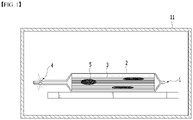
- FIG. 1 is a cross-sectional view schematically showing a degassing process performed by a conventional method of manufacturing a battery cell
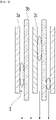
- FIG. 2 is a cross-sectional view specifically showing a state in which activated gas is trapped between an electrode and a separator in FIG. 1 .
- gas is collected in a gas pocket unit 2a by pressing a cell including a pouch case 2 and an electrode assembly 3 inside the chamber 11, and a degassing hole 4 is then formed by piercing the gas pocket unit 2a. Thereafter, by making the inside of the chamber 11 become vacuum, the activation gas inside the pouch case 2 is removed by discharging the activation gas to the outside through the degassing hole 4.
- the discharge of gas inside the battery cell 1 may be maximized during the process of pressing the battery cell 1, but the discharge amount of the electrolyte solution existing in the cell also increases. On the other hand, it takes a long time until the electrolyte solution discharged by the pressure is absorbed into the electrode and the separator, and if the electrolyte solution is not sufficiently absorbed in the electrode and the separator, the quality of the battery cell is deteriorated.
- an aspect of the present invention provides a battery cell activation method capable of easily discharging gas trapped between a separator and an electrode inside an electrode assembly of a battery cell, and preventing discharge of a large amount of electrolyte solution during a gas discharging process, and a method of manufacturing a battery cell including the same.
- a method of activating a battery cell includes: first-pressing a battery cell to initial-charge and discharge the battery cell under a pressurization condition for the battery cell; exposing the battery cell to a vacuum condition; second-pressing the battery cell; aging the battery cell; and degassing the battery cell by removing internal gas of the battery cell.
- a pressure P2 applied to the battery cell during the second-pressing of the battery cell is lower than a pressure P1 applied to the battery cell during the first-pressing of the battery cell.
- the pressure P1 applied to the battery cell during the first-pressing of the battery cell and the pressure P2 applied to the battery cell during the second-pressing of the battery cell satisfy a following condition 1: 0.5 ⁇ P 1 / P 2 ⁇ 10
- P1 denotes an average pressure (kgf/cm 2 ) which is applied to press the battery cell during the first-pressing of the battery cell
- P2 denotes an average pressure (kgf/cm 2 ) which is applied to press the battery cell during the second-pressing of the battery cell.
- the pressure P2 applied to the battery cell during the second-pressing of the battery cell is in a range of 0.5 to 3 kgf/cm 2 on average.
- the second-pressing of the battery cell includes: pressing a region opposite to a side of the battery cell where a gas pocket has been formed; and pressing a region of a side of the battery cell where the gas pocket has been formed.
- the second-pressing of the battery cell includes discharging internal gas of the battery cell by sequentially pressing the battery cell from one side to the other side. At this time, the second-pressing of the battery cell is performed by sequentially pressing the battery cell from one side to the other side using a pressing roller.
- the first-pressing of the battery cell is performed by pressing two surfaces of the battery cell using pressing plates.
- the exposing of the battery cell to the vacuum condition is performed by depressurizing an inner side of a chamber in a state that the battery cell is positioned inside the chamber.
- the exposing of the battery cell to the vacuum condition is performed by repeating a venting process of discharging gas inside the chamber n times in a state that the battery cell is positioned in the chamber.
- the n is an integer between 2 and 50.
- the exposing of the battery cell to the vacuum condition is performed by placing the battery cell inside the chamber, and a width of the vacuum chamber is greater than a width of the battery cell.
- the present invention provides method of manufacturing a battery cell including the above-described process of activating a battery cell.
- the method of manufacturing a battery cell according to the present invention includes activating the battery cell using the method of activating a battery cell.
- the battery cell is a pouch-type battery cell and has a gas pocket connected to an inside of the battery cell at one side.
- the method further includes sealing the battery cell and removing the gas pocket, after the activating of the battery cell.
- gas which is trapped between a separator and an electrode inside an electrode assembly of a battery cell, can be easily discharged. Further, in the activation method of the battery cell, it is possible to prevent discharge of a large amount of electrolyte solution during the pressing process of the battery cell by including first and second pressing steps.
- the present invention provides a method of activating a battery cell and a method of manufacturing a battery cell including the same.
- the present invention provides a method of activating a battery cell and a method of manufacturing a battery cell including the same.
- gas remaining in the battery cell may be easily discharged by including the first and second pressing steps.
- the pressure P2 applied to the battery cell during the second-pressing of the battery cell is set to be lower than the pressure P1 applied to the battery cell during the first-pressing of the battery cell in order to prevent discharge of a large amount of electrolyte solution during the degassing process.
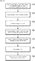
- FIG. 3 is a flowchart of a method of activating a battery cell according to one embodiment of the present invention.
- a method of activating a battery cell includes: first-pressing a battery cell to initial-charge and discharge the battery cell under a pressurization condition for the battery cell (S10); exposing the battery cell to a vacuum condition (S20); second-pressing the battery cell (S30); aging the battery cell (S40); and degassing the battery cell by removing internal gas of the battery cell (S50).
- a pressure P2 applied to the battery cell during the second-pressing of the battery cell is lower than a pressure P1 applied to the battery cell during the first-pressing of the battery cell.
- the battery cell may be a pouch-type unit cell.
- the battery cell may be a pouch-type battery cell having a structure that an electrode assembly having a positive electrode/ separator/ negative electrode structure is embedded in an exterior material of the laminate sheet in a state that is connected to electrode leads formed outside the exterior material.
- the positive electrode and the negative electrode are manufactured by coating a slurry such as an electrode active material, a binder resin, a conductive agent, and other additives on at least one surface of the current collector.
- a slurry such as an electrode active material, a binder resin, a conductive agent, and other additives on at least one surface of the current collector.
- a general positive electrode active material such as a lithium-containing transition metal oxide is used as the electrode active material
- a general negative electrode active material such as a lithium metal for intercalating and discharging lithium ions, a carbon material, and a metal compound, or a mixture thereof may be used as the electrode active material.
- the separator blocks a contact between the positive electrode and the negative electrode in order to prevent a short circuit therebetween, and a porous polymer film may be used to allow charge transfer during the charge and discharge.
- the pouch case is formed as a first case and a second case, which are obtained by processing a sheet material to have a predetermined shape, are coupled to each other at an upper side and a lower side, respectively.
- the sheet material constituting the pouch case is composed of a multi-layer structure obtained by lamination of an outer resin layer made of an insulating material such as polyethylene terephthalate (PET) or nylon at the outermost side, a metal layer made of an aluminum material which maintains mechanical strength and prevents permeation of moisture and oxygen, and an interior resin layer made of a polyolefin-based material which functions as a sealing material by having thermal adhesiveness.
- a pouch case before the completion of the degassing process to be described later is manufactured as a size greater than the volume of the electrode assembly and has a receiving portion for accommodating an electrode assembly, and a gas pocket unit which forms a space for collection of the activation gas which is generated during the charge and discharge process.
- a process of casing an electrode assembly in a pouch case, injecting an electrolyte solution into the pouch case, and impregnating the electrode assembly in the electrolyte solution is performed.
- the electrolyte solution is permeated into a space between the positive electrode, the negative electrode and the separator by capillary force.
- the opening is sealed in order to completely seal the electrode assembly.
- an activation process of charging and discharging the battery cell is performed. Since the battery cell in the initial period is a non-activated cell in a discharged state, it does not have a function as a battery.
- the activation process is a process of activating the cell in a discharged state by charging and discharging the cell a few times to be able to function as a battery.
- the method of activating a battery cell according to the present invention includes a first-pressing step (S10) of first-pressing a battery cell to initial-charge and discharge the battery cell under a pressurization condition for the battery cell. Further, since the initial charge and discharge process of the battery cell is performed by an electrochemical reaction, gas is generated as a side reaction during the charge and discharge process. At this time, since generated gas becomes the cause of the cell resistance increase, capacity and lifespan decrease, external appearance defect, it is necessary to remove gas after the charge and discharge process.
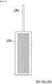
- FIG. 4 is a diagram schematically showing a first-pressing step in a battery cell activation method according to one embodiment of the present invention.
- the battery cell 100 may discharge generated gas, and the gas inside the battery cell 100 may be discharged to the outside by pressing the battery cell 100 with the pressing jig 130.
- the battery cell 100 includes a receiving portion 120b for accommodating an electrode assembly, and a gas pocket unit 120a which forms a space for collecting activation gas generated during the charge and discharge process.
- the pressing jig 130 includes plates which have the battery cell 100 between the plates and press the battery cell 100 from two sides. Further, the electric current may pass through the electrode lead of the battery cell at the time of charging the battery cell.
- the method of activating a battery cell according to the present invention includes a vacuum step (S20) of exposing the battery cell to a vacuum condition.
- the vacuum step (S20) of exposing of the battery cell to a vacuum condition is a process of inducing the interface interval between the electrode and the separator to be widened by expanding the battery cell by generating a pressure difference between the inside and the outside of the activated cell.
- FIGS. 5 and 6 are diagrams schematically showing a state before and after a vacuum step in a battery cell activation method according to one embodiment of the present invention.
- the vacuum step (S20) is performed in a state that places the battery cell in the vacuum chamber 110.
- the width of the vacuum chamber 110 may be greater than that of the battery cell.
- the vacuum step in the case of depressurizing the inside of the vacuum chamber 110, the battery cell may expand, and it is preferable that the width of the vacuum chamber 110 is sufficient for accommodating the expanded battery cell 110.
- the inside of the vacuum chamber 110 is depressurized in a state that places the battery cell 100 in the vacuum chamber 110.
- the pouch case is changed from a normal state to an expanded state by performing vacuum control for the inside of the vacuum chamber 110 for accommodating the activated cell, namely, making the inside of the vacuum chamber 110 become vacuum or setting the external pressure to be lower than the internal pressure of the pouch case by adjusting the vacuum degree.
- the receiving portion 120b and the gas pocket unit 120a of the pouch case are expanded to swell in a direction perpendicular to the flat surface, and at the same time, an interface interval between the electrodes 3a and 3c and the separator 3b constituting the electrode assembly 3 is widened, thereby increasing the absorption of the electrolyte solution. Further, it is possible to maximize the resorption of the electrolyte solution which is discharged as the interface interval between the electrodes 3a and 3c and the separator 3b constituting the electrode assembly 3 is widened. Further, gas, which has been trapped between the interfaces, may be smoothly moved.
- the vacuum step (S20) of exposing of the battery cell 100 to the vacuum condition includes repeating a venting process of discharging gas inside the chamber 110 n times in a state that the battery cell 100 is positioned in the chamber 110.
- the n is an integer between 2 and 50.
- repeating the venting process n times means repeating the process of making the inside of the chamber 110 become vacuum and the venting process of discharging gas n times.
- the process may be repeated 2 to 40 times, 2 to 30 times, 2 to 20 times or 2 to 10 times.
- the electrode assembly inside the battery cell 1 00 may maximize absorption of the electrolyte solution.
- the method of activating a battery cell according to the present invention includes a second-pressing step (S30) of second-pressing the battery cell.
- the second-pressing step (S30) is a process for additionally removing gas which has not been discharged during the first-pressing step.
- a pressure P2 applied to the battery cell during the second-pressing step of the battery cell is lower than a pressure P1 applied to the battery cell during the first-pressing of the battery cell.
- the pressure P1 to the battery cell during the first-pressing of the battery cell and the pressure P2 applied to the battery cell during the second-pressing of the battery cell satisfy a following condition 1: 1.1 ⁇ P 1 / P 2 ⁇ 10
- P1 denotes an average pressure (kgf/cm 2 ) which is applied to press the battery cell during the first-pressing of the battery cell
- P2 denotes an average pressure (kgf/cm 2 ) which is applied to press the battery cell during the second-pressing of the battery cell.
- the pressure P1 applied to the battery cell during the first-pressing of the battery cell and the pressure P2 applied to the battery cell during the second-pressing of the battery cell may have a relationship that 1.1 ⁇ P1/P2 ⁇ 10, 1.5 ⁇ P1/P2 ⁇ 8, or 2 ⁇ P1/P2 ⁇ 5.
- the pressure P2 applied to the battery cell during the second-pressing of the battery cell may be in a range of 0.5 to 1 kgf/cm 2 on average.
- the pressure P2 applied to the battery cell during the second-pressing of the battery cell is set to be lower than the pressure P1 applied to the battery cell during the first-pressing of the battery cell in order to prevent discharge of a large amount of electrolyte solution during the pressing process. Namely, in the method of activating a battery cell according to the present invention, as the first-pressing step and the second-pressing step satisfy the above condition 1, the discharge of gas inside the battery cell can be maximized, and the discharge of the electrolyte solution can be prevented.
- FIG. 7 is a flowchart of a method of activating a battery cell according to another embodiment of the present invention.
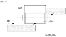
- the second-pressing step of the battery cell (S30) includes: a lower pressing step (S31) of pressing a region opposite to a side of the battery cell where a gas pocket unit has been formed; and an upper pressing step (S32) of pressing a region of a side of the battery cell where the gas pocket unit has been formed (S32).
- a lower pressing step S31
- an upper pressing step S32
- the second-pressing step will be described in detail with reference to FIG. 7 .
- FIGS. 8 and 9 schematically show a lower pressing step and an upper pressing step in a second-pressing step of a battery cell activation method according to another embodiment of the present invention.
- the lower pressing step (S31) includes pressing the lower region of the pouch-type battery cell with respect to the electrode lead of the pouch-type battery cell
- the upper pressing step (S32) includes pressing the upper region of the pouch-type battery cell with respect to the electrode lead of the pouch-type battery cell.
- the lower pressing step (S31) only the lower region of the battery cell is pressed so that gas, which is trapped in the lower portion of the battery cell, may be moved to the upper region.
- the upper pressing step (S31) only the upper region of the battery cell is pressed so that the gas, which is discharged from the lower region, may be moved to the gas pocket unit 120a. As such, gas inside the battery cell 100 may be easily discharged to the gas pocket unit 120a, and the gas discharge may be maximized.
- the second-pressing step (S30) of the battery cell includes discharging internal gas of the battery cell 100 by sequentially pressing the battery cell 100 from one side to the other side.
- one side means a region opposite to a region where the gas pocket unit 120a is formed in the receiving portion 120b, and the other side means a region where the gas pocket is formed.
- the second-pressing step (S30) of the battery cell includes sequentially pressing the battery cell 100 from one side to the other side using a pressing roller.
- activation gas may be induced to be moved in the direction of the gas pocket unit by applying certain pressure toward the region where the gas pocket of the pouch case has been formed using the roller.
- the method of activating a battery cell according to the present invention includes an aging step (S40) of aging the battery cell.
- the aging step may be a step of stabilizing the SEI film formed during the charging step.
- the method includes a degassing step (S50) of degassing the battery cell by removing internal gas of the battery cell. More specifically, the degassing step includes a process of forming a hole, which functions as a path, through which gas inside the pouch case may be discharged to the outside, by perforating at least part of the gas pocket. At this time, it is possible to form the degassing hole by punching the first and second cases all together in the gas pocket unit of the pouch case, but in this case, the possibility of the leakage of the electrolyte solution together with the gas through the degassing hole may increase. In the present example, the hole may be formed only on the gas pocket in order to reduce the possibility of leakage of electrolyte solution.
- the degassing step (S50) is a process of discharging the activation gas to the outside of the pouch case through the degassing hole by negative pressure by forming the vacuum state inside the chamber again.
- the activation gas which has been collected in the gas pocket unit, may be naturally discharged to the outside through the hole, but as shown in the present embodiment, if a vacuum state is formed in the chamber again, the gas discharge efficiency increases by the negative pressure, and the gas remaining in the electrode assembly may also be discharged.
- the present invention provides method of manufacturing a battery cell including the above-described process of activating a battery cell.
- the method of manufacturing a battery cell according to the present invention includes activating the battery cell using the above-described method of activating a battery cell.
- the battery cell is a pouch-type battery cell and has a gas pocket connected to an inside of the battery cell at one side.
- the method further includes sealing the battery cell and removing the gas pocket, after the activating of the battery cell.
- the gas pocket is a space for collecting activation gas, and when the degassing process is completed, it is a dead space in the cell, and accordingly, after trimmed, a new sealing line is formed by heat-fusing the corresponding portion of the first case and the second case. Likewise, after the secondary-sealing is completed, a wing folding process of closely attaching the sealing line of the pouch case on the side surface of the pouch case by folding the sealing line may be added.
- gas which is trapped between a separator and an electrode inside an electrode assembly of a battery cell, can be easily discharged. Further, in the activation method of the battery cell, it is possible to prevent discharge of a large amount of electrolyte solution during the pressing process of the battery cell by including first and second pressing steps.
Landscapes
- Chemical & Material Sciences (AREA)
- Chemical Kinetics & Catalysis (AREA)
- Electrochemistry (AREA)
- General Chemical & Material Sciences (AREA)
- Engineering & Computer Science (AREA)
- Manufacturing & Machinery (AREA)
- Secondary Cells (AREA)
Applications Claiming Priority (2)
| Application Number | Priority Date | Filing Date | Title |
|---|---|---|---|
| KR1020200152525A KR102900629B1 (ko) | 2020-11-16 | 2020-11-16 | 전지 셀 활성화 방법 및 이를 포함하는 전지 셀 제조 방법 |
| PCT/KR2021/015938 WO2022103076A1 (ko) | 2020-11-16 | 2021-11-04 | 전지 셀 활성화 방법 및 이를 포함하는 전지 셀 제조 방법 |
Publications (3)
| Publication Number | Publication Date |
|---|---|
| EP4064400A1 true EP4064400A1 (de) | 2022-09-28 |
| EP4064400A4 EP4064400A4 (de) | 2023-11-29 |
| EP4064400B1 EP4064400B1 (de) | 2026-04-29 |
Family
ID=81601525
Family Applications (1)
| Application Number | Title | Priority Date | Filing Date |
|---|---|---|---|
| EP21892244.1A Active EP4064400B1 (de) | 2020-11-16 | 2021-11-04 | Batteriezellen-aktivierungsverfahren und batteriezellenherstellungsverfahren damit |
Country Status (5)
| Country | Link |
|---|---|
| US (1) | US12456749B2 (de) |
| EP (1) | EP4064400B1 (de) |
| KR (1) | KR102900629B1 (de) |
| CN (1) | CN114930590A (de) |
| WO (1) | WO2022103076A1 (de) |
Cited By (1)
| Publication number | Priority date | Publication date | Assignee | Title |
|---|---|---|---|---|
| JP2025514448A (ja) * | 2022-12-23 | 2025-05-02 | エルジー エナジー ソリューション リミテッド | 過リチウムマンガン系酸化物を含むリチウム二次電池の製造方法 |
Families Citing this family (3)
| Publication number | Priority date | Publication date | Assignee | Title |
|---|---|---|---|---|
| US20230155163A1 (en) * | 2021-11-15 | 2023-05-18 | Sk On Co., Ltd. | Formation Method For Secondary Battery |
| KR20250055690A (ko) | 2023-10-18 | 2025-04-25 | 주식회사 엘지에너지솔루션 | 전지 셀 제조장치 및 이를 이용한 전지 셀 제조방법 |
| CN121263895A (zh) * | 2023-11-23 | 2026-01-02 | 株式会社Lg新能源 | 电池单体制造方法 |
Family Cites Families (30)
| Publication number | Priority date | Publication date | Assignee | Title |
|---|---|---|---|---|
| CN1197190C (zh) * | 2000-01-27 | 2005-04-13 | 索尼株式会社 | 凝胶电解液电池的制造方法 |
| JP5145648B2 (ja) | 2006-04-14 | 2013-02-20 | 日産自動車株式会社 | リチウムイオン二次電池 |
| DE102010052397A1 (de) * | 2010-11-24 | 2012-05-24 | Li-Tec Battery Gmbh | Verfahren und Vorrichtung zum Befüllen einer elektrochemischen Zelle |
| JP6163739B2 (ja) | 2011-12-05 | 2017-07-19 | 日産自動車株式会社 | フィルム外装電気デバイスの製造方法及び製造装置 |
| KR20130134963A (ko) * | 2012-05-31 | 2013-12-10 | 주식회사 엘지화학 | 가스 포켓부가 구비된 파우치형 전지 포장재, 및 이를 이용한 디개싱 공정 |
| KR101602466B1 (ko) | 2012-11-28 | 2016-03-10 | 주식회사 엘지화학 | 파우치형 이차 전지의 제조 방법 및 이에 의하여 제조된 파우치형 이차 전지 |
| JP5966891B2 (ja) | 2012-11-30 | 2016-08-10 | 株式会社村田製作所 | 蓄電デバイスの製造方法 |
| CN105408755A (zh) | 2013-07-24 | 2016-03-16 | 汽车能源供应公司 | 二次电池的检查方法 |
| JP6283487B2 (ja) * | 2013-09-27 | 2018-02-21 | オートモーティブエナジーサプライ株式会社 | 非水電解質二次電池の製造方法 |
| KR101669714B1 (ko) * | 2013-11-29 | 2016-10-27 | 주식회사 엘지화학 | 폴리머 전지의 제조 방법 |
| CN105934846B (zh) * | 2014-01-24 | 2019-06-28 | 日产自动车株式会社 | 电器件 |
| KR102195734B1 (ko) * | 2014-01-27 | 2020-12-28 | 삼성에스디아이 주식회사 | 파우치형 배터리셀의 제조방법 |
| JP6682203B2 (ja) * | 2015-06-03 | 2020-04-15 | 株式会社エンビジョンAescジャパン | 二次電池の製造方法 |
| JP6488969B2 (ja) * | 2015-09-30 | 2019-03-27 | 日産自動車株式会社 | 二次電池の製造装置 |
| KR20170101582A (ko) | 2016-02-29 | 2017-09-06 | 주식회사 엘지화학 | 활성화 공정 중 압력을 변화시키는 과정을 포함하는 리튬 이차전지의 제조 방법 |
| KR20170111614A (ko) * | 2016-03-29 | 2017-10-12 | 주식회사 엘지화학 | 이차 전지 제조 방법 및 장치 |
| WO2018002296A1 (en) | 2016-06-30 | 2018-01-04 | Robert Bosch Gmbh | Method of forming a secondary battery |
| KR102256599B1 (ko) * | 2016-09-01 | 2021-05-26 | 주식회사 엘지에너지솔루션 | 가압 지그 및 이를 이용한 이차전지 제조 방법 |
| KR102282481B1 (ko) * | 2016-09-01 | 2021-07-27 | 주식회사 엘지에너지솔루션 | 가압 지그 및 이를 이용한 이차전지 제조 방법 |
| KR102217443B1 (ko) * | 2016-11-30 | 2021-02-22 | 주식회사 엘지화학 | 이차전지 가스제거장치 및 가스제거방법 |
| KR102067715B1 (ko) * | 2016-12-01 | 2020-01-17 | 주식회사 엘지화학 | 배터리 셀 디가싱 장치 |
| CN106602161B (zh) | 2016-12-29 | 2020-03-20 | 惠州亿纬创能电池有限公司 | 锂离子电池的化成方法及锂离子电池 |
| KR102200990B1 (ko) * | 2017-01-11 | 2021-01-11 | 주식회사 엘지화학 | 전지셀의 제조 및 활성화 방법 |
| KR102381443B1 (ko) | 2017-02-13 | 2022-03-31 | 주식회사 엘지에너지솔루션 | 파우치형 이차전지의 제조방법 |
| KR101793162B1 (ko) | 2017-03-14 | 2017-11-03 | 주식회사 테크네트 | 리튬전지 포메이션 챔버용 셀가압장치 |
| KR102447619B1 (ko) * | 2017-09-18 | 2022-09-27 | 주식회사 엘지에너지솔루션 | 지그를 이용한 고정 과정을 포함하는 파우치형 전지셀 제조방법 |
| KR102320016B1 (ko) * | 2017-12-15 | 2021-11-02 | 주식회사 엘지에너지솔루션 | 이차전지의 제조방법 |
| KR102740245B1 (ko) | 2018-11-05 | 2024-12-06 | 주식회사 엘지에너지솔루션 | 전지 제조용 가스 제거기 및 이를 이용한 전지 제조 방법 |
| CN210110979U (zh) | 2019-07-31 | 2020-02-21 | 惠州市德合盛科技有限公司 | 锂电池化成治具 |
| KR20210068168A (ko) * | 2019-11-29 | 2021-06-09 | 현대자동차주식회사 | 리튬이온 이차전지 제조 시스템 및 그 방법 |
-
2020
- 2020-11-16 KR KR1020200152525A patent/KR102900629B1/ko active Active
-
2021
- 2021-11-04 EP EP21892244.1A patent/EP4064400B1/de active Active
- 2021-11-04 CN CN202180008060.6A patent/CN114930590A/zh active Pending
- 2021-11-04 WO PCT/KR2021/015938 patent/WO2022103076A1/ko not_active Ceased
- 2021-11-04 US US17/789,596 patent/US12456749B2/en active Active
Cited By (2)
| Publication number | Priority date | Publication date | Assignee | Title |
|---|---|---|---|---|
| JP2025514448A (ja) * | 2022-12-23 | 2025-05-02 | エルジー エナジー ソリューション リミテッド | 過リチウムマンガン系酸化物を含むリチウム二次電池の製造方法 |
| US12609357B2 (en) | 2022-12-23 | 2026-04-21 | Lg Energy Solution, Ltd. | Method for manufacturing lithium secondary battery comprising lithium-rich manganese based oxide |
Also Published As
| Publication number | Publication date |
|---|---|
| EP4064400B1 (de) | 2026-04-29 |
| US20230049301A1 (en) | 2023-02-16 |
| CN114930590A (zh) | 2022-08-19 |
| WO2022103076A1 (ko) | 2022-05-19 |
| KR20220066470A (ko) | 2022-05-24 |
| KR102900629B1 (ko) | 2025-12-15 |
| EP4064400A4 (de) | 2023-11-29 |
| US12456749B2 (en) | 2025-10-28 |
Similar Documents
| Publication | Publication Date | Title |
|---|---|---|
| EP4064400B1 (de) | Batteriezellen-aktivierungsverfahren und batteriezellenherstellungsverfahren damit | |
| KR102381443B1 (ko) | 파우치형 이차전지의 제조방법 | |
| KR101650858B1 (ko) | 전지셀의 제조방법 및 전지셀의 가스 제거 장치 | |
| CN104380514B (zh) | 二次电池的制造方法和制造装置 | |
| KR101165066B1 (ko) | 미실링 잉여부를 구비하는 파우치형 이차전지 | |
| KR101713068B1 (ko) | 활성화된 전지셀의 가스 제거 장치 및 전지셀 제조방법 | |
| KR102649923B1 (ko) | 파우치형 이차전지의 제조방법 | |
| KR101602466B1 (ko) | 파우치형 이차 전지의 제조 방법 및 이에 의하여 제조된 파우치형 이차 전지 | |
| EP4068444B1 (de) | Vorrichtung und verfahren zur herstellung einer sekundärbatterie | |
| KR20170033601A (ko) | 탈기 과정의 공정성이 향상된 이차전지의 제조 방법 | |
| KR101791535B1 (ko) | 가스 제거 장치에 의한 전지셀의 제조방법 | |
| US20240030483A1 (en) | Cell assembly and all solid-state battery comprising the same | |
| KR20180107859A (ko) | 활성화된 전지셀의 가스 제거 장치 | |
| CN108140871A (zh) | 制造二次电池的方法和制造电极组件的方法 | |
| JP4880811B2 (ja) | 電池の製造方法 | |
| US20230223600A1 (en) | Lithium-ion battery formation process | |
| JP2003217671A (ja) | 密閉型電池の製造方法と密閉型電池のシール性評価方法 | |
| KR20240028022A (ko) | 파우치형 전지셀의 포메이션 방법 및 이를 포함하는 활성화 방법 | |
| KR20210033329A (ko) | 파우치형 이차전지의 실링 장치 및 이를 이용한 실링 방법 | |
| EP4726833A1 (de) | Sekundärbatteriepressvorrichtung und sekundärbatteriepressverfahren damit | |
| KR102957144B1 (ko) | 이차 전지 및 그의 제조 방법 | |
| KR20260062608A (ko) | 배터리 셀의 제조방법 | |
| KR20260022072A (ko) | 이차 전지 제조 설비 및 이를 이용한 이차 전지를 제조하는 방법 | |
| EP1643582A1 (de) | Methode zur Herstellung von nachladbaren Batterien | |
| KR20250168907A (ko) | 전고체 전지의 제조 장치 |
Legal Events
| Date | Code | Title | Description |
|---|---|---|---|
| STAA | Information on the status of an ep patent application or granted ep patent |
Free format text: STATUS: THE INTERNATIONAL PUBLICATION HAS BEEN MADE |
|
| PUAI | Public reference made under article 153(3) epc to a published international application that has entered the european phase |
Free format text: ORIGINAL CODE: 0009012 |
|
| STAA | Information on the status of an ep patent application or granted ep patent |
Free format text: STATUS: REQUEST FOR EXAMINATION WAS MADE |
|
| 17P | Request for examination filed |
Effective date: 20220621 |
|
| AK | Designated contracting states |
Kind code of ref document: A1 Designated state(s): AL AT BE BG CH CY CZ DE DK EE ES FI FR GB GR HR HU IE IS IT LI LT LU LV MC MK MT NL NO PL PT RO RS SE SI SK SM TR |
|
| A4 | Supplementary search report drawn up and despatched |
Effective date: 20231031 |
|
| RIC1 | Information provided on ipc code assigned before grant |
Ipc: H01M 10/058 20100101ALI20231025BHEP Ipc: H01M 50/116 20210101ALI20231025BHEP Ipc: H01M 50/30 20210101ALI20231025BHEP Ipc: H01M 10/04 20060101AFI20231025BHEP |
|
| DAV | Request for validation of the european patent (deleted) | ||
| DAX | Request for extension of the european patent (deleted) | ||
| GRAP | Despatch of communication of intention to grant a patent |
Free format text: ORIGINAL CODE: EPIDOSNIGR1 |
|
| STAA | Information on the status of an ep patent application or granted ep patent |
Free format text: STATUS: GRANT OF PATENT IS INTENDED |
|
| INTG | Intention to grant announced |
Effective date: 20251219 |
|
| P01 | Opt-out of the competence of the unified patent court (upc) registered |
Free format text: CASE NUMBER: UPC_APP_0005017_4064400/2026 Effective date: 20260211 |
|
| GRAS | Grant fee paid |
Free format text: ORIGINAL CODE: EPIDOSNIGR3 |
|
| GRAA | (expected) grant |
Free format text: ORIGINAL CODE: 0009210 |
|
| STAA | Information on the status of an ep patent application or granted ep patent |
Free format text: STATUS: THE PATENT HAS BEEN GRANTED |
|
| AK | Designated contracting states |
Kind code of ref document: B1 Designated state(s): AL AT BE BG CH CY CZ DE DK EE ES FI FR GB GR HR HU IE IS IT LI LT LU LV MC MK MT NL NO PL PT RO RS SE SI SK SM TR |
|
| REG | Reference to a national code |
Ref country code: CH Ref legal event code: F10 Free format text: ST27 STATUS EVENT CODE: U-0-0-F10-F00 (AS PROVIDED BY THE NATIONAL OFFICE) Effective date: 20260429 |