EP4064448A1 - Batteriemodul - Google Patents
Batteriemodul Download PDFInfo
- Publication number
- EP4064448A1 EP4064448A1 EP20891250.1A EP20891250A EP4064448A1 EP 4064448 A1 EP4064448 A1 EP 4064448A1 EP 20891250 A EP20891250 A EP 20891250A EP 4064448 A1 EP4064448 A1 EP 4064448A1
- Authority
- EP
- European Patent Office
- Prior art keywords
- plate
- welding bead
- welding
- electrode tab
- battery module
- Prior art date
- Legal status (The legal status is an assumption and is not a legal conclusion. Google has not performed a legal analysis and makes no representation as to the accuracy of the status listed.)
- Granted
Links
Images


Classifications
-
- B—PERFORMING OPERATIONS; TRANSPORTING
- B23—MACHINE TOOLS; METAL-WORKING NOT OTHERWISE PROVIDED FOR
- B23K—SOLDERING OR UNSOLDERING; WELDING; CLADDING OR PLATING BY SOLDERING OR WELDING; CUTTING BY APPLYING HEAT LOCALLY, e.g. FLAME CUTTING; WORKING BY LASER BEAM
- B23K26/00—Working by laser beam, e.g. welding, cutting or boring
- B23K26/20—Bonding
- B23K26/21—Bonding by welding
- B23K26/24—Seam welding
- B23K26/242—Fillet welding, i.e. involving a weld of substantially triangular cross section joining two parts
-
- H—ELECTRICITY
- H01—ELECTRIC ELEMENTS
- H01M—PROCESSES OR MEANS, e.g. BATTERIES, FOR THE DIRECT CONVERSION OF CHEMICAL ENERGY INTO ELECTRICAL ENERGY
- H01M50/00—Constructional details or processes of manufacture of the non-active parts of electrochemical cells other than fuel cells, e.g. hybrid cells
- H01M50/50—Current conducting connections for cells or batteries
- H01M50/502—Interconnectors for connecting terminals of adjacent batteries; Interconnectors for connecting cells outside a battery casing
- H01M50/505—Interconnectors for connecting terminals of adjacent batteries; Interconnectors for connecting cells outside a battery casing comprising a single busbar
-
- B—PERFORMING OPERATIONS; TRANSPORTING
- B23—MACHINE TOOLS; METAL-WORKING NOT OTHERWISE PROVIDED FOR
- B23K—SOLDERING OR UNSOLDERING; WELDING; CLADDING OR PLATING BY SOLDERING OR WELDING; CUTTING BY APPLYING HEAT LOCALLY, e.g. FLAME CUTTING; WORKING BY LASER BEAM
- B23K26/00—Working by laser beam, e.g. welding, cutting or boring
- B23K26/20—Bonding
- B23K26/21—Bonding by welding
- B23K26/24—Seam welding
- B23K26/26—Seam welding of rectilinear seams
-
- B—PERFORMING OPERATIONS; TRANSPORTING
- B23—MACHINE TOOLS; METAL-WORKING NOT OTHERWISE PROVIDED FOR
- B23K—SOLDERING OR UNSOLDERING; WELDING; CLADDING OR PLATING BY SOLDERING OR WELDING; CUTTING BY APPLYING HEAT LOCALLY, e.g. FLAME CUTTING; WORKING BY LASER BEAM
- B23K26/00—Working by laser beam, e.g. welding, cutting or boring
- B23K26/20—Bonding
- B23K26/32—Bonding taking account of the properties of the material involved
- B23K26/323—Bonding taking account of the properties of the material involved involving parts made of dissimilar metallic material
-
- B—PERFORMING OPERATIONS; TRANSPORTING
- B23—MACHINE TOOLS; METAL-WORKING NOT OTHERWISE PROVIDED FOR
- B23K—SOLDERING OR UNSOLDERING; WELDING; CLADDING OR PLATING BY SOLDERING OR WELDING; CUTTING BY APPLYING HEAT LOCALLY, e.g. FLAME CUTTING; WORKING BY LASER BEAM
- B23K31/00—Processes relevant to this subclass, specially adapted for particular articles or purposes, but not covered by any single one of main groups B23K1/00 - B23K28/00
- B23K31/12—Processes relevant to this subclass, specially adapted for particular articles or purposes, but not covered by any single one of main groups B23K1/00 - B23K28/00 relating to investigating the properties, e.g. the weldability, of materials
-
- H—ELECTRICITY
- H01—ELECTRIC ELEMENTS
- H01M—PROCESSES OR MEANS, e.g. BATTERIES, FOR THE DIRECT CONVERSION OF CHEMICAL ENERGY INTO ELECTRICAL ENERGY
- H01M50/00—Constructional details or processes of manufacture of the non-active parts of electrochemical cells other than fuel cells, e.g. hybrid cells
- H01M50/10—Primary casings; Jackets or wrappings
- H01M50/102—Primary casings; Jackets or wrappings characterised by their shape or physical structure
- H01M50/105—Pouches or flexible bags
-
- H—ELECTRICITY
- H01—ELECTRIC ELEMENTS
- H01M—PROCESSES OR MEANS, e.g. BATTERIES, FOR THE DIRECT CONVERSION OF CHEMICAL ENERGY INTO ELECTRICAL ENERGY
- H01M50/00—Constructional details or processes of manufacture of the non-active parts of electrochemical cells other than fuel cells, e.g. hybrid cells
- H01M50/20—Mountings; Secondary casings or frames; Racks, modules or packs; Suspension devices; Shock absorbers; Transport or carrying devices; Holders
- H01M50/204—Racks, modules or packs for multiple batteries or multiple cells
- H01M50/207—Racks, modules or packs for multiple batteries or multiple cells characterised by their shape
- H01M50/211—Racks, modules or packs for multiple batteries or multiple cells characterised by their shape adapted for pouch cells
-
- H—ELECTRICITY
- H01—ELECTRIC ELEMENTS
- H01M—PROCESSES OR MEANS, e.g. BATTERIES, FOR THE DIRECT CONVERSION OF CHEMICAL ENERGY INTO ELECTRICAL ENERGY
- H01M50/00—Constructional details or processes of manufacture of the non-active parts of electrochemical cells other than fuel cells, e.g. hybrid cells
- H01M50/50—Current conducting connections for cells or batteries
- H01M50/502—Interconnectors for connecting terminals of adjacent batteries; Interconnectors for connecting cells outside a battery casing
- H01M50/507—Interconnectors for connecting terminals of adjacent batteries; Interconnectors for connecting cells outside a battery casing comprising an arrangement of two or more busbars within a container structure, e.g. busbar modules
-
- H—ELECTRICITY
- H01—ELECTRIC ELEMENTS
- H01M—PROCESSES OR MEANS, e.g. BATTERIES, FOR THE DIRECT CONVERSION OF CHEMICAL ENERGY INTO ELECTRICAL ENERGY
- H01M50/00—Constructional details or processes of manufacture of the non-active parts of electrochemical cells other than fuel cells, e.g. hybrid cells
- H01M50/50—Current conducting connections for cells or batteries
- H01M50/502—Interconnectors for connecting terminals of adjacent batteries; Interconnectors for connecting cells outside a battery casing
- H01M50/514—Methods for interconnecting adjacent batteries or cells
- H01M50/516—Methods for interconnecting adjacent batteries or cells by welding, soldering or brazing
-
- H—ELECTRICITY
- H01—ELECTRIC ELEMENTS
- H01M—PROCESSES OR MEANS, e.g. BATTERIES, FOR THE DIRECT CONVERSION OF CHEMICAL ENERGY INTO ELECTRICAL ENERGY
- H01M50/00—Constructional details or processes of manufacture of the non-active parts of electrochemical cells other than fuel cells, e.g. hybrid cells
- H01M50/50—Current conducting connections for cells or batteries
- H01M50/531—Electrode connections inside a battery casing
- H01M50/533—Electrode connections inside a battery casing characterised by the shape of the leads or tabs
-
- H—ELECTRICITY
- H01—ELECTRIC ELEMENTS
- H01M—PROCESSES OR MEANS, e.g. BATTERIES, FOR THE DIRECT CONVERSION OF CHEMICAL ENERGY INTO ELECTRICAL ENERGY
- H01M50/00—Constructional details or processes of manufacture of the non-active parts of electrochemical cells other than fuel cells, e.g. hybrid cells
- H01M50/50—Current conducting connections for cells or batteries
- H01M50/531—Electrode connections inside a battery casing
- H01M50/534—Electrode connections inside a battery casing characterised by the material of the leads or tabs
-
- H—ELECTRICITY
- H01—ELECTRIC ELEMENTS
- H01M—PROCESSES OR MEANS, e.g. BATTERIES, FOR THE DIRECT CONVERSION OF CHEMICAL ENERGY INTO ELECTRICAL ENERGY
- H01M50/00—Constructional details or processes of manufacture of the non-active parts of electrochemical cells other than fuel cells, e.g. hybrid cells
- H01M50/50—Current conducting connections for cells or batteries
- H01M50/531—Electrode connections inside a battery casing
- H01M50/536—Electrode connections inside a battery casing characterised by the method of fixing the leads to the electrodes, e.g. by welding
-
- H—ELECTRICITY
- H01—ELECTRIC ELEMENTS
- H01M—PROCESSES OR MEANS, e.g. BATTERIES, FOR THE DIRECT CONVERSION OF CHEMICAL ENERGY INTO ELECTRICAL ENERGY
- H01M50/00—Constructional details or processes of manufacture of the non-active parts of electrochemical cells other than fuel cells, e.g. hybrid cells
- H01M50/50—Current conducting connections for cells or batteries
- H01M50/531—Electrode connections inside a battery casing
- H01M50/54—Connection of several leads or tabs of plate-like electrode stacks, e.g. electrode pole straps or bridges
-
- B—PERFORMING OPERATIONS; TRANSPORTING
- B23—MACHINE TOOLS; METAL-WORKING NOT OTHERWISE PROVIDED FOR
- B23K—SOLDERING OR UNSOLDERING; WELDING; CLADDING OR PLATING BY SOLDERING OR WELDING; CUTTING BY APPLYING HEAT LOCALLY, e.g. FLAME CUTTING; WORKING BY LASER BEAM
- B23K2101/00—Articles made by soldering, welding or cutting
- B23K2101/36—Electric or electronic devices
- B23K2101/38—Conductors
-
- B—PERFORMING OPERATIONS; TRANSPORTING
- B23—MACHINE TOOLS; METAL-WORKING NOT OTHERWISE PROVIDED FOR
- B23K—SOLDERING OR UNSOLDERING; WELDING; CLADDING OR PLATING BY SOLDERING OR WELDING; CUTTING BY APPLYING HEAT LOCALLY, e.g. FLAME CUTTING; WORKING BY LASER BEAM
- B23K2103/00—Materials to be soldered, welded or cut
- B23K2103/08—Non-ferrous metals or alloys
- B23K2103/10—Aluminium or alloys thereof
-
- B—PERFORMING OPERATIONS; TRANSPORTING
- B23—MACHINE TOOLS; METAL-WORKING NOT OTHERWISE PROVIDED FOR
- B23K—SOLDERING OR UNSOLDERING; WELDING; CLADDING OR PLATING BY SOLDERING OR WELDING; CUTTING BY APPLYING HEAT LOCALLY, e.g. FLAME CUTTING; WORKING BY LASER BEAM
- B23K2103/00—Materials to be soldered, welded or cut
- B23K2103/08—Non-ferrous metals or alloys
- B23K2103/12—Copper or alloys thereof
-
- B—PERFORMING OPERATIONS; TRANSPORTING
- B23—MACHINE TOOLS; METAL-WORKING NOT OTHERWISE PROVIDED FOR
- B23K—SOLDERING OR UNSOLDERING; WELDING; CLADDING OR PLATING BY SOLDERING OR WELDING; CUTTING BY APPLYING HEAT LOCALLY, e.g. FLAME CUTTING; WORKING BY LASER BEAM
- B23K2103/00—Materials to be soldered, welded or cut
- B23K2103/18—Dissimilar materials
-
- Y—GENERAL TAGGING OF NEW TECHNOLOGICAL DEVELOPMENTS; GENERAL TAGGING OF CROSS-SECTIONAL TECHNOLOGIES SPANNING OVER SEVERAL SECTIONS OF THE IPC; TECHNICAL SUBJECTS COVERED BY FORMER USPC CROSS-REFERENCE ART COLLECTIONS [XRACs] AND DIGESTS
- Y02—TECHNOLOGIES OR APPLICATIONS FOR MITIGATION OR ADAPTATION AGAINST CLIMATE CHANGE
- Y02E—REDUCTION OF GREENHOUSE GAS [GHG] EMISSIONS, RELATED TO ENERGY GENERATION, TRANSMISSION OR DISTRIBUTION
- Y02E60/00—Enabling technologies; Technologies with a potential or indirect contribution to GHG emissions mitigation
- Y02E60/10—Energy storage using batteries
Definitions
- the present disclosure relates to a battery module, and more particularly, to a battery module having improved mechanical properties and electrical properties.
- a method of overlap welding a single or a plurality of electrode tabs and a bus bar is generally used.
- this method has a large deviation in tensile strength after welding, and a high possibility of welding defects such as weak welding depending on the pressurized conditions.
- electrode tabs of multiple specifications in a unit module need to be bent and cut for welding, which leads to increase in process and management costs.
- a resistance of each cell is non-uniform due to a difference in lengths of electrode tabs for each cell specification within a module, which is highly likely to adversely affect long-term durability.
- An object of the present disclosure is to provide a battery module capable of having a welded part having excellent tensile strength and contact resistance by appropriately controlling welding of heterogeneous materials between an electrode tab and a bus bar.
- a battery module includes: a plurality of battery cells each including an electrode tab; and a bus bar connected to the electrode tab to electrically connect the plurality of battery cells to each other, in which the bus bar includes a plate in which a plurality of holes are formed, the electrode tabs of each of the battery cells are inserted into at least a part of the plurality of holes of the plate, the electrode tab inserted into the hole and the plate are coupled to each other by a welding bead, and the welding bead satisfies Equations 1 and 2 below.
- Equation 1 W is a width of the welding bead based on a cross section of the welding bead in a thickness direction of the plate, and T is a thickness of the electrode tab. 0 ⁇ H ⁇ 3 T
- Equation 2 H is a height of the welding bead based on the cross section of the welding bead in the thickness direction of the plate, and T is the thickness of the electrode tab.
- a battery module in another aspect, includes: a plurality of battery cells each including an electrode tab; and a bus bar connected to the electrode tab to electrically connect the plurality of battery cells to each other, in which the bus bar includes a plate in which a plurality of holes are formed, the electrode tabs of each of the battery cells are inserted into at least a part of the plurality of holes of the plate, the electrode tab inserted into the hole and the plate are coupled to each other by a welding bead, and the welding bead satisfies Equation 3 below.
- Equation 3 A is a cross-sectional area of the welding bead based on a cross section of the welding bead in a thickness direction of the plate, and T is a thickness of the electrode tab.
- A may be T 2 to 12T 2 .
- the welding bead may further satisfy Equation 4 below. 0.4 T ⁇ D ⁇ 2 T
- Equation 4 D is a penetration depth of the welding bead into a hole based on the cross section of the welding bead in the thickness direction of the plate, and T is the thickness of the electrode tab.
- the electrode tab and the plate may be made of different materials from each other.
- the welding bead may be derived from 70 to 99 wt% of a first base material and a balance of a second base material by using the electrode tab as the first base material for welding and the plate as the second base material for welding.
- the electrode tab may be made of aluminum, and the plate may be made of copper.
- the plate or the electrode tab may include a surface plating layer.
- the surface plating layer may include Ni, Sn, Si, Mg, Fe, Mn, Zn, Cr, Li, Ca, or an alloy thereof.
- the thickness of the electrode tab may be 0.2 mm or more.
- the thickness of the electrode tab may be 0.2 mm to 1.0 mm.
- the thickness of the plate may be 0.5 mm or more.
- the welding bead may include: a cover part having a convex shape covering the hole on one of two opposing surfaces in the thickness direction of the plate; and a pillar part charged into the hole, based on the cross section of the welding bead in the thickness direction of the plate.
- the welding bead In the cross section of the welding bead in the thickness direction of the plate, the welding bead may be left-right asymmetrical with respect to a center line of the hole.
- the welding bead In the cross section of the welding bead in the thickness direction of the plate, by setting, as a boundary point, a point where an interface between the welding bead and one of two opposing surfaces in the thickness direction of the plate and a surface of the one surface meet, the welding bead may have left-right asymmetry of a ratio of L1 : L2, which is a shortest distance between left and right two boundary points, and the center line of the hole is 1 : 1.2 to 3.
- the plate may include a protrusion formed around a location where the hole is formed.
- the plate may include a tab connection part protruding outwardly of the plate from an outer periphery of the hole.
- the hole may include an insertion part having an open side so that the electrode tab is slide-inserted.
- the battery cell may be a pouch-type battery cell.
- a part such as a film (layer), a region, a component, etc.
- this includes not only the case where a part is directly above in contact with another part, but also a case where another film (layer), another region, or another component is interposed therebetween.
- a welding strength (tensile strength) is generally managed to be 3.5 kgf/mm 2 or more. This is about 70% or more of the tensile strength of 5.5kgf/mm 2 of pure Al, which satisfies the welding strength generally required for products and also satisfies the mechanical strength requirements such as vibration and impact resistance of products.
- the present disclosure may make an electrode tap processing shape of all unit cells constituting a module the same without bending or cutting electrode tabs of a plurality of adjacent cells (battery cells) into more than one shape for welding for electrical connection of the electrode tabs.
- the processed unit cells are stacked to constitute a laminate including a predetermined number of cells, and then, plate may be assembled in a direction in which the electrode tabs are inserted for electrical connection.
- the plate may have holes (slots) with a predetermined interval through which the preprocessed electrode tab may penetrate and come out, and the holes (slots) may correspond to each electrode tab, and the plate have a surface that protrudes in a direction in which the electrode tab passes along an outer periphery of the hole.
- the electrode tab protrudes through the plate, and then welding is performed by irradiating a laser beam to the protruding welded part.
- various shapes and qualities of electrode tabs may be formed according to the thickness, material, protruding amount, plate material, plating material, thickness, welding length, welding speed, laser power, and laser irradiation pattern of the electrode tab, the present inventors were able to set the optimal quality control criteria by identifying the degree of influence of various factors through the experiment planning method.
- the present inventors have investigated the correlation between the mechanical/electrical properties according to the shape of the cross section of the welding bead through repeated research and analysis when welding heterogeneous materials in which the material of the electrode tab and the material of the plate are different, particularly when welding Cu-Al heterogeneous materials, thereby deriving the shape of the welding bead to be described below.
- the welding strength may be improved more than twice without deteriorating the electrical properties on the welded part, and the electrical resistance of the module may be reduced.
- mechanical properties may be improved without substantially deteriorating electrical properties by the composition of the welding bead that varies depending on the external shape of the welding bead and the shape of the welding bead when welding the heterogeneous materials, for example, by Cu-Al dilution in the case of the Cu-Al heterogeneous material.
- the dilution represents the degree of contribution of each welding base material (in the case of the present disclosure, the plate and the electrode tab) that contributes to the overall welding with or without filler addition, and in an image of a cross section of welding metal, the dilution may be measured as the area where each component is melted and mixed. It is known that this dilution varies depending on welding heat input, thermal properties, and a shape and dimension of an initial joint.
- the welding bead may be derived from 70 to 99 wt% of the first base material and the balance (1 to 30 wt%) of the second base material and may advantageously be derived from 75 to 99 wt% of the first base material and the balance (1 to 25 wt%) of the second base material. That is, the dilution of the first base material may be 85 to 99% and the dilution of the second base material may be 1 to 15%, and advantageously, the dilution of the first base material may be 89 to 99% and the dilution of the second base material may be 1 to 11%.
- a surface plating layer may be formed on the electrode tab serving as the first base material (welding base material) and/or the plate serving as the second base material. That is, the electrode tab and/or the plate may include the surface plating layer, and in particular, the electrode tab, in which electrical/chemical stability for an electrolyte is to be ensured, may include the surface plating layer.
- the surface plating layer for ensuring the electrical/chemical stability for the electrolyte may include Ni, Sn, Si, Mg, Fe, Mn, Zn, Cr, Li, Ca, or an alloy thereof.
- the dilution of the surface plating layer itself may also be calculated through the elemental weight % (wt%) analysis of the welding bead containing the above-described first base material, second base material, and plating component.
- composition of the welding metal (welding bead) throughout the welding may be quantified by energy dispersive spectroscopy (EDS) for various process factors.
- EDS energy dispersive spectroscopy Table 1 below summarizes the composition content (wt%) of the welding metal under various welding conditions through preliminary experiments and the calculated dilution when welding the heterogeneous materials of the Cu plate-Al electrode tab.
- a method of calculating a dilution is well known in the art, and therefore, will not be presented separately.
- the size of the welding bead is a very important indicator to determine the overall composition and dilution. Specifically, the size of the welding bead is directly related to the load-bearing capacity of the welding metal. Specifically, when welding the heterogeneous materials of the Cu plate-Al electrode tab, it generally means that, as the size of the welding bead increases, more Al is contained, and it was found that the Cu dilution and the IMC formation were reduced and thus the occurrence of cracks is reduced, resulting in forming the stronger welded parts.
- the present disclosure has a welding strength of 7.0 kgf/mm 2 or more, which is more than twice the existing overlap welding strength of 3.5 kgf/mm 2 , and the present disclosure is presented by determining the specific conditions of the welding bead in which stable welding quality is achieved by minimizing the occurrence of intermetallic compounds (IMC) such as Al x Cu x or Cu x Al x .
- IMC intermetallic compounds
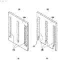
- FIG. 2 is a diagram illustrating a structure in which the battery tabs 120 of each battery cell 110 are electrically connected by a bus bar 150 in a laminate in which the battery cells 110 are stacked according to an exemplary embodiment of the present disclosure
- FIG. 3 is a diagram illustrating a bus bar provided in a battery module according to an exemplary embodiment of the present disclosure.
- the battery module 100 includes a plurality of battery cells 110 and electrode tabs 120 drawn out from the battery cells 110.
- the battery module 100 of the present disclosure includes the bus bar 150, and the bus bar 150 includes a plate 150a and a hole 150c formed in the plate.
- the plate may include a plurality of holes 150c accommodating each of the plurality of electrode tabs 120, and each hole 150c may have a shape and size corresponding to a cross section of the electrode tab 120 so that an end portion of the electrode tab 120 may be inserted into the hole 150c.
- each hole 150c may include an insertion part 151 whose one side is open so that the electrode tab 120 may be slide-inserted.
- the insertion part may have a tapered shape that widens toward the open side so that the electrode tab 120 may be easily slide-inserted into the hole 150c, but the shape of the insertion part 151 is not limited thereto.
- one or more holes 150c are formed in the plate 150a, and by welding the electrode tabs 120 inserted into each hole 150c, the plurality of welded battery cells 110 may be electrically connected.
- FIG. 4 is a diagram illustrating a battery module having a welding bead according to an exemplary embodiment of the present disclosure.
- the electrode tab 120 is inserted into the hole 150c formed in the plate 150a, and then the battery cells 110 are connected by welding, so it is not necessary to separately deform the shape of the electrode tab 120 as in the related art.
- one or more holes 150c may be formed in the plate 150a to correspond to the number of battery cells 110 to be connected. Therefore, in order to electrically connect the battery cells 110, the battery cells 110 may be electrically connected without changing the shape of the electrode tab 120, regardless of the number of battery cells 110 to be connected.
- the plate 150a constituting the bus bar 150 includes one or more holes 150c having a predetermined interval, and the plurality of battery cells 110 may be electrically connected by welding the electrode tabs 120 inserted into and penetrating through the holes 150c.
- the electrode tabs 120 since the electrode tabs 120 may be inserted and welded into each hole 150c, the plurality of battery cells 110 welded through the bus bar 150 may be electrically connected to each other.
- the hole 150c may be formed in a slit shape.
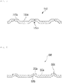
- FIG. 5 is a diagram illustrating a bus bar 150 according to another exemplary embodiment of the present disclosure.
- a plate 150a may include a protrusion 150b formed around a position where the hole 150c is formed. That is, the protrusion 150b may be formed in the bus bar 150 according to the exemplary embodiment of the present disclosure.
- the protrusion 150b is formed at a position where the hole 150c is formed, and may serve to guide the electrode tab 120 to be inserted into the hole 150c.
- the plate 150c includes the plurality of holes 150c formed at a predetermined interval, and includes the protrusion 150b formed around the position where the hole 150c is formed, and the plurality of battery cells may be electrically connected by welding the electrode tabs (not illustrated) inserted into the holes 150c.
- FIG. 6 is a diagram illustrating the bus bar 150 according to another exemplary embodiment of the present disclosure.
- the plate 150a may include a tab connection part 151a.
- the tab connection part 151a is formed to protrude from the outer periphery of each hole 150c in the direction in which the electrode tab 120 protrudes. Then, when the battery cells 110 are electrically connected to each other by laser welding, the electrode tab 120 melted by the laser L may contact the tab connection part 151a to be electrically connected to the bus bar.
- an intaglio groove 151b is formed on the opposite surface of the tab connection part 151a around the hole 150c to guide the electrode tab 120 to be inserted into the hole 150c.
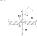
- FIG. 7 is a diagram illustrating a state in which the laser L is irradiated in a longitudinal direction (d in FIG. 7 , the same as the protrusion direction) of the electrode tab 120 according to another exemplary embodiment of the present disclosure.
- the laser L may be irradiated obliquely with respect to a central axis of the protruding electrode tab 120 inserted into the hole 150c in a longitudinal direction d1.
- the laser L is directly irradiated to the battery cell 110 due to an error during welding and the possibility that an accident may occur may be minimized.
- the welding process of the distal surface of the electrode tab 120 may be confirmed with the naked eye, thereby improving the quality and production speed of the battery module.
- welding beads of various shapes may be obtained by laser welding.
- the present inventors have found that the shape and size of the welding bead is closely related to the composition of the welding metal based on the dilution of the base material, and were confirmed that the mechanical properties including the tensile strength of the welding site may be greatly improved without deteriorating the electrical properties when the welding bead has a specific shape and size to be described below.
- the electrode tab inserted into the hole and the plate are coupled to each other by the welding bead, and the welding bead has a width W and a height H that satisfy Equations 1 and 2 below. 0 ⁇ W ⁇ 7 T
- Equation 1 W is a width of the welding bead based on a cross section of the welding bead in a thickness direction of the plate, and T is a thickness of the electrode tab. 0 ⁇ H ⁇ 3 T
- Equation 2 H is a height of the welding bead based on the cross section of the welding bead in the thickness direction of the plate, and T is the thickness of the electrode tab.
- the unit of T may be mm.
- the cross section of the welding bead in the thickness direction of the plate means a cross section cut by an imaginary plane parallel to the thickness direction of the plate(imaginary plane having the thickness direction as in-plane), but may mean the cross section of the welding cut so that the area of the welding bead is minimized.
- an imaginary plane p making the cut cross section of the welding bead may be an imaginary plane that is parallel to a thickness direction t1 of the plate and parallel to a thickness direction t2 of the electrode tab, and the cross section of the welding bead may mean a cross section cut by the above-described imaginary plane p.
- Equations 1 and 2 described above are particularly important when the electrode tab and the plate are made of different materials (metal materials). That is, when the width W of the welding bead is 7T or more in the heterogeneous material welding, the formation of the intermetallic compounds between the heterogeneous materials may be induced.
- the electrode tab is made of aluminum and the plate (bus bar) is made of copper
- the width of the welding bead is 7T or more
- the melting amount of the Cu plate (bus bar) increases and the formation of the intermetallic compound on the Cu-Al interface is induced, so the deterioration in the quality of the welded part, such as microcracks in the welded part and increased resistance, may be induced.
- Equation 1 is a geometrical parameter that greatly affects the dilution between the welding base metals in the welding bead
- Equation 2 is a geometrical parameter that greatly affects the shape of the welding bead itself.
- the welding bead includes: a cover part having a convex shape covering the hole on one of two opposing surfaces in the thickness direction of the plate, based on the cross section of the welding bead in the thickness direction of the plate; and a pillar part charged into the hole.
- Equation 2 is a geometrical parameter that affects the shape of the welding bead itself, and when the height H of the welding bead is 3T or more, the length of the pillar part of the welding bead is shortened, which may cause a problem in that the interfacial bonding strength decreases.
- the width W of the welding bead may be 2T to 6T, more advantageously 3T to 6T, and the height H may be 0.5T to 2T, more advantageously 1T to 2T.
- the welding bead has improved tensile strength and low contact resistance, and thus, exhibit excellent welding properties.
- the welding bead satisfies the width and height, even if specific welding conditions such as a heat gradient state caused during welding or specific welding conditions such as a laser irradiation method during welding are changed, it is possible to ensure stable and reproducible constant welding quality (improved welding strength, excellent electrical properties of the welding site, etc.).
- the electrode tab inserted into the hole and the plate are coupled to each other by the welding bead, and the welding bead may satisfy Equation 3 below. 0 ⁇ A ⁇ 21 T 2
- Equation 3 A is a cross-sectional area of the welding bead based on a cross section of the welding bead in a thickness direction of the plate, and T is a thickness of the electrode tab.
- the cross section of the welding bead in the thickness direction of the plate is the same as described above based on Equations 1 and 2 above.
- a cross-sectional area A of a welding bead 170 may be less than 21T 2 . If the cross-sectional area is 21T 2 (mm 2 ) or more, there may be various types of problems such as the increased occurrence of the intermetallic compound (IMC), the decreased welding strength, and the occurrence of cracks in the welded part. More preferably, the cross-sectional area of the welding bead based on the cross section of the welding bead may satisfy T 2 to 12T 2 , and more advantageously 3T 2 to 12T 2 . When the cross-sectional area of the welding bead is satisfied, the welding bead has the improved tensile strength and the low contact resistance, and thus, may exhibit the excellent welding properties, and may exhibit the constant welding properties without being substantially affected by the specific welding conditions.
- IMC intermetallic compound
- the welding bead may satisfy Equation 1 and Equation 2 and further satisfy Equation 3, and independently, may satisfy Equation 3 and further satisfy Equation 1, Equation 2 or Equation 1 and Equation 2.
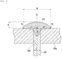
- FIG. 9 is a schematic cross-sectional view illustrating that the welding bead 170 is formed by heating and melting an end portion of the electrode tab 120 that has penetrated through the hole 150c of the plate 150a of the bus bar according to the exemplary embodiment of the present disclosure.
- the width W of the bead may be the width of the cover part based on the cross section of the welding bead.
- the width W of the bead may mean a distance between left and right two boundary points p1 and p2 by setting, the boundary points p1 and p2, a point where an interface between the welding bead 170 and one of the two opposing surfaces in the thickness direction of the plate 150a and a surface of the one surface meet in the cross section of the welding bead in the thickness direction of the plate.
- the width of the bead when the left and right boundary points p1 and p2 are located at the same height, the width of the bead is illustrated as in FIG. 9 , and when the left and right boundary points p1 and p2 are not located at the same height, the width of the bead may be defined as the shortest distance between the two boundary points.
- the height H of the bead may be the maximum height of the cover part based on the cross section of the welding bead.
- the height H of the bead may be a distance (shortest distance) between the imaginary line connecting the left and right two boundary points p1 and p2 and a highest point of the cover part by setting, the boundary points p1 and p2, the point where the interface between the welding bead 170 and one of the two opposing surfaces in the thickness direction of the plate 150a and the surface of the one surface meet in the cross section of the welding bead in the thickness direction of the plate.
- the width of the bead is only illustrated as in FIG. 9 , and the height of the bead may be defined as the shortest distance between the imaginary line connecting the two boundary points and the highest point of the cover part.
- the welding bead may further satisfy Equation 4. 0.4 T ⁇ D ⁇ 2 T
- D is a penetration depth of the welding bead into the hole based on the cross section of the welding bead in the thickness direction of the plate
- T is the thickness of the electrode tab.
- the penetration depth may be a distance (shortest distance) between the imaginary line connecting the left and right boundary points p1 and p2 and the lowest point of the welding bead located inside the hole.
- the penetration depth may correspond to the length of the pillar part.
- the penetration depth may be a factor related to the mechanical properties and the dilution of the plate due to the shape of the welding bead itself.
- the penetration depth satisfies a penetration depth of 0.4T to 2T, preferably 0.5T to 1.5T, and more preferably 0.5T to 1.0T
- the dilution of the plate is controlled to 5% or less and the mechanical properties may be improved by the shape of the welding bead.
- the welding bead 170 in the cross section of the welding bead in the thickness direction of the plate, may be left-right symmetrical or left-right asymmetrical with respect to a center line CL of the hole.
- the center line of the hole may be the same as the center line of the battery tab inserted into the hole.
- the left-right symmetry may mean that the ratio of L1 : L2 is 1 : 1 to 1.2 by setting the shortest distance between the left and right two boundary points p1 and p2 and the center line of the hole as L1 and L2, and setting the longer length as L2 when L1 and L2 are different from each other. Referring to FIG.
- the left-right asymmetry may mean that the ratio of L1 : L2 exceeds 1 : 1.2, specifically, the ratio of L1 : L2 is 1 : 1.2 to 3, specifically 1 : 1.2 to 2.5.
- the left-right asymmetric structure may be mainly affected by the irradiation direction of the laser, and as described above based on FIG. 7 , such asymmetric structures may appear when the laser is irradiated obliquely. It is known that the left-right asymmetric structure of the welding bead is not favorable to the mechanical properties of the welding site.
- the mechanical properties (welding strength) of the welding site are not significantly affected by the asymmetric structure of the welding bead. That is, even with the left-right symmetrical structure or the left-right asymmetrical structure, welding characteristics having substantially constant and uniform and improved mechanical properties may be exhibited.
- the electrode tab material-plate material may be an Al material-Cu material or a Cu material-Al material.
- the Al material may be aluminum having a purity of 90% or more, and specifically, aluminum having a purity of 95% or more, 99% or more, or 99.5% or more.
- the Al material may be industrial pure aluminum, and commercial products may include Al1000 series (UNS #) such as Al1050, Al1100, or Al1200.
- the Cu material may be copper with a purity of 98% or more, 99% or more, or 99.3% or more.
- the Cu material may be industrial pure copper, and commercial products may include C10100 to C13000 series (UNS #), such as C11000, C10100, C10200, and C12500.
- the electrode tab 120 is configured to penetrate through the hole 150b in a direction perpendicular to the surface of the plate 150a, and the thickness thereof is preferably 0.2 mm or more. More preferably, the thickness of the electrode tab may be 0.2 to 1.0 mm. When the electrode tab has a thickness of 0.2 mm or more, it is advantageous because the welding bead having the above-described specific shape may be manufactured by the laser welding and the welding bead having a plate dilution of 11% or less may be manufactured.
- the plate 150a preferably has a thickness of 0.5 mm or more, and may have, for example, a thickness of 0.5 mm to 10 mm, 1 mm to 8 mm, or 1 mm to 6 mm, but is not necessarily limited thereto.
- the battery cell may be a pouch-type battery cell.
- the pouch-type battery cell may be a battery cell in which an electrode assembly including a cathode, an anode, and a separator interposed between the cathode and the anode is sealed in a pouch in the state of being impregnated in an electrolyte (electrolytic solution).
- the pouch may have a multi-layer film structure in which a metal film such as an aluminum film is interposed between an outer film and an inner film, but is not limited thereto.
- the electrode tabs of each of the plurality of pouch-type battery cells stacked in one direction are inserted and welded into each hole of the plate, so the plurality of pouch-type battery cells may be electrically connected to each other.
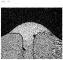
- FIG. 10 is a photograph illustrating the shape of the welding bead according to the exemplary embodiment of the present disclosure formed by welding the Al electrode tab to the Cu plate with the heterogeneous materials by the method of FIG. 8 .
- the surface of the plate in contact with the welding bead is inclined downward in the longitudinal direction toward the outer peripheral portion of the welding bead.
- the surface of the plate bonded to the formed welding bead is configured so that the hole is inclined downwardly from the center toward the outer peripheral portion of the welding bead, and thus, the shape of the welding bead may be smoothly formed, thereby preventing the deterioration in the welding strength due to the rough shapes such as notch.
Landscapes
- Chemical & Material Sciences (AREA)
- Chemical Kinetics & Catalysis (AREA)
- Electrochemistry (AREA)
- General Chemical & Material Sciences (AREA)
- Engineering & Computer Science (AREA)
- Physics & Mathematics (AREA)
- Optics & Photonics (AREA)
- Mechanical Engineering (AREA)
- Plasma & Fusion (AREA)
- Connection Of Batteries Or Terminals (AREA)
Applications Claiming Priority (3)
| Application Number | Priority Date | Filing Date | Title |
|---|---|---|---|
| KR20190149643 | 2019-11-20 | ||
| KR1020200155110A KR102817987B1 (ko) | 2019-11-20 | 2020-11-19 | 배터리 모듈 |
| PCT/KR2020/016432 WO2021101300A1 (ko) | 2019-11-20 | 2020-11-20 | 배터리 모듈 |
Publications (3)
| Publication Number | Publication Date |
|---|---|
| EP4064448A1 true EP4064448A1 (de) | 2022-09-28 |
| EP4064448A4 EP4064448A4 (de) | 2024-01-17 |
| EP4064448B1 EP4064448B1 (de) | 2024-07-24 |
Family
ID=75981345
Family Applications (1)
| Application Number | Title | Priority Date | Filing Date |
|---|---|---|---|
| EP20891250.1A Active EP4064448B1 (de) | 2019-11-20 | 2020-11-20 | Batteriemodul |
Country Status (6)
| Country | Link |
|---|---|
| US (2) | US20220407187A1 (de) |
| EP (1) | EP4064448B1 (de) |
| KR (2) | KR102736730B1 (de) |
| CN (2) | CN118073782A (de) |
| DE (1) | DE202020006073U1 (de) |
| WO (1) | WO2021101300A1 (de) |
Cited By (2)
| Publication number | Priority date | Publication date | Assignee | Title |
|---|---|---|---|---|
| EP4414116A1 (de) * | 2023-01-31 | 2024-08-14 | SK On Co., Ltd. | Schweisswulst und sekundärbatteriemodul damit |
| IT202300005298A1 (it) * | 2023-03-21 | 2024-09-21 | Ferrari Spa | Metodo di saldatura per saldare un elettrodo ad un elemento di collegamento provvisto di una cavita' passante conformata ad alloggiare l'elettrodo |
Families Citing this family (2)
| Publication number | Priority date | Publication date | Assignee | Title |
|---|---|---|---|---|
| KR20240125336A (ko) * | 2023-02-10 | 2024-08-19 | 에스케이온 주식회사 | 배터리 모듈 제조방법 및 배터리 모듈 |
| KR102682684B1 (ko) | 2023-08-16 | 2024-07-10 | 주식회사 아시아나노텍 | 생분해 가능한 친환경 토양 응집제를 포함하는 화재확산 방지제 및 토양 복원제 |
Family Cites Families (16)
| Publication number | Priority date | Publication date | Assignee | Title |
|---|---|---|---|---|
| KR100284034B1 (ko) * | 1998-09-09 | 2001-11-02 | 장용균 | 리튬이온 전지의 밀봉구조 |
| JP4829587B2 (ja) * | 2005-10-14 | 2011-12-07 | 日本電気株式会社 | 電気デバイス集合体及びその製造方法 |
| US9028986B2 (en) * | 2009-01-07 | 2015-05-12 | A123 Systems Llc | Fuse for battery cells |
| KR101124964B1 (ko) * | 2010-04-28 | 2012-03-27 | 주식회사 이아이지 | 이차전지의 양극리드 또는 음극리드를 외부 부재와 연결하는 방법 |
| JP5982652B2 (ja) * | 2014-04-15 | 2016-08-31 | パナソニックIpマネジメント株式会社 | 異材金属接合体 |
| US10062931B2 (en) * | 2015-04-22 | 2018-08-28 | Johnson Controls Technology Company | Welding process for battery module components |
| US10115997B2 (en) * | 2016-05-12 | 2018-10-30 | Bosch Battery Systems Llc | Prismatic electrochemical cell |
| US11088410B2 (en) * | 2016-12-23 | 2021-08-10 | Sk Innovation Co., Ltd. | Battery module |
| KR102117859B1 (ko) * | 2016-12-23 | 2020-06-02 | 에스케이이노베이션 주식회사 | 배터리 모듈 |
| KR102244120B1 (ko) * | 2017-04-18 | 2021-04-22 | 주식회사 엘지화학 | 전극 리드와 버스바의 결합 구조가 개선된 배터리 모듈 |
| KR102082498B1 (ko) * | 2017-04-26 | 2020-02-27 | 주식회사 엘지화학 | 전극 리드와 버스바의 결합 구조가 개선된 배터리 모듈 및 그 제조 방법 |
| KR102209769B1 (ko) * | 2017-06-07 | 2021-01-28 | 주식회사 엘지화학 | 배터리 모듈 |
| WO2019013591A1 (ko) * | 2017-07-14 | 2019-01-17 | 주식회사 엘지화학 | 배터리 모듈 |
| KR102598811B1 (ko) * | 2018-03-06 | 2023-11-03 | 에스케이온 주식회사 | 배터리 모듈 및 이의 제조방법 |
| US20190296316A1 (en) * | 2018-03-26 | 2019-09-26 | GM Global Technology Operations LLC | Battery tab having a localized welded joint and method of making the same |
| KR102637834B1 (ko) | 2018-05-02 | 2024-02-19 | 에스케이온 주식회사 | 배터리 모듈 |
-
2020
- 2020-11-20 US US17/778,780 patent/US20220407187A1/en active Pending
- 2020-11-20 DE DE202020006073.9U patent/DE202020006073U1/de active Active
- 2020-11-20 CN CN202410305757.5A patent/CN118073782A/zh active Pending
- 2020-11-20 EP EP20891250.1A patent/EP4064448B1/de active Active
- 2020-11-20 CN CN202080081096.2A patent/CN114868303B/zh active Active
- 2020-11-20 WO PCT/KR2020/016432 patent/WO2021101300A1/ko not_active Ceased
-
2023
- 2023-07-04 KR KR1020230086701A patent/KR102736730B1/ko active Active
-
2025
- 2025-02-05 US US19/046,503 patent/US20250183491A1/en active Pending
- 2025-06-02 KR KR1020250072487A patent/KR20250086583A/ko active Pending
Cited By (2)
| Publication number | Priority date | Publication date | Assignee | Title |
|---|---|---|---|---|
| EP4414116A1 (de) * | 2023-01-31 | 2024-08-14 | SK On Co., Ltd. | Schweisswulst und sekundärbatteriemodul damit |
| IT202300005298A1 (it) * | 2023-03-21 | 2024-09-21 | Ferrari Spa | Metodo di saldatura per saldare un elettrodo ad un elemento di collegamento provvisto di una cavita' passante conformata ad alloggiare l'elettrodo |
Also Published As
| Publication number | Publication date |
|---|---|
| KR20230107186A (ko) | 2023-07-14 |
| CN118073782A (zh) | 2024-05-24 |
| CN114868303B (zh) | 2024-04-05 |
| DE202020006073U1 (de) | 2024-10-14 |
| EP4064448B1 (de) | 2024-07-24 |
| US20220407187A1 (en) | 2022-12-22 |
| KR102736730B1 (ko) | 2024-12-03 |
| WO2021101300A1 (ko) | 2021-05-27 |
| CN114868303A (zh) | 2022-08-05 |
| KR20250086583A (ko) | 2025-06-13 |
| EP4064448A4 (de) | 2024-01-17 |
| US20250183491A1 (en) | 2025-06-05 |
Similar Documents
| Publication | Publication Date | Title |
|---|---|---|
| US20250183491A1 (en) | Battery module | |
| KR102817987B1 (ko) | 배터리 모듈 | |
| EP3351339B1 (de) | Geschweisste struktur eines metallteils und schweissverfahren | |
| US9017871B2 (en) | Negative-electrode terminal for cell | |
| CN103733377B (zh) | 二次电池用铝罐体及其制造方法 | |
| US9559347B2 (en) | Negative electrode terminal for battery and method for producing negative electrode terminal for battery | |
| JP2017168267A (ja) | 導電部材、及び、導電部材の製造方法 | |
| JP6052162B2 (ja) | 非水電解質二次電池およびその製造方法 | |
| KR102829145B1 (ko) | 원통형 이차전지의 제조방법 | |
| US20230299430A1 (en) | Method for manufacturing joined body, joined body, and battery module | |
| JP5546997B2 (ja) | 溶接方法および電池の製造方法および電池 | |
| JP5726430B2 (ja) | 電池ケース本体用アルミニウム合金板および電池ケース | |
| EP4414116A1 (de) | Schweisswulst und sekundärbatteriemodul damit | |
| EP4415148A2 (de) | Batteriemodulherstellungsverfahren und batteriemodul | |
| EP4382240A1 (de) | Sekundärbatteriemodul | |
| JP2015011807A (ja) | 角形二次電池および組電池 | |
| US20250149746A1 (en) | Battery module and method for manufacturing the same | |
| KR20250168659A (ko) | 레이저 용접용 클래드재, 레이저 용접용 클래드재를 사용한 접합 구조 및 전지의 제조 방법 | |
| CN121566066A (zh) | 焊接结构、顶盖组件、单体电芯及电池包 | |
| JPH11162448A (ja) | 鉛蓄電池の製造法 |
Legal Events
| Date | Code | Title | Description |
|---|---|---|---|
| REG | Reference to a national code |
Ref country code: DE Ref legal event code: R138 Ref document number: 202020006073 Country of ref document: DE Free format text: GERMAN DOCUMENT NUMBER IS 602020034656 |
|
| STAA | Information on the status of an ep patent application or granted ep patent |
Free format text: STATUS: THE INTERNATIONAL PUBLICATION HAS BEEN MADE |
|
| PUAI | Public reference made under article 153(3) epc to a published international application that has entered the european phase |
Free format text: ORIGINAL CODE: 0009012 |
|
| STAA | Information on the status of an ep patent application or granted ep patent |
Free format text: STATUS: REQUEST FOR EXAMINATION WAS MADE |
|
| 17P | Request for examination filed |
Effective date: 20220617 |
|
| AK | Designated contracting states |
Kind code of ref document: A1 Designated state(s): AL AT BE BG CH CY CZ DE DK EE ES FI FR GB GR HR HU IE IS IT LI LT LU LV MC MK MT NL NO PL PT RO RS SE SI SK SM TR |
|
| DAV | Request for validation of the european patent (deleted) | ||
| DAX | Request for extension of the european patent (deleted) | ||
| P01 | Opt-out of the competence of the unified patent court (upc) registered |
Effective date: 20230602 |
|
| A4 | Supplementary search report drawn up and despatched |
Effective date: 20231215 |
|
| RIC1 | Information provided on ipc code assigned before grant |
Ipc: B23K 103/18 20060101ALN20231211BHEP Ipc: B23K 103/12 20060101ALN20231211BHEP Ipc: B23K 103/10 20060101ALN20231211BHEP Ipc: B23K 101/38 20060101ALN20231211BHEP Ipc: B23K 101/36 20060101ALN20231211BHEP Ipc: B23K 26/26 20140101ALI20231211BHEP Ipc: B23K 26/323 20140101ALI20231211BHEP Ipc: H01M 50/54 20210101ALI20231211BHEP Ipc: H01M 50/516 20210101ALI20231211BHEP Ipc: H01M 50/505 20210101ALI20231211BHEP Ipc: B23K 26/242 20140101ALI20231211BHEP Ipc: H01M 50/211 20210101ALI20231211BHEP Ipc: H01M 50/105 20210101ALI20231211BHEP Ipc: H01M 50/543 20210101ALI20231211BHEP Ipc: H01M 50/50 20210101AFI20231211BHEP |
|
| GRAP | Despatch of communication of intention to grant a patent |
Free format text: ORIGINAL CODE: EPIDOSNIGR1 |
|
| STAA | Information on the status of an ep patent application or granted ep patent |
Free format text: STATUS: GRANT OF PATENT IS INTENDED |
|
| RIC1 | Information provided on ipc code assigned before grant |
Ipc: B23K 103/18 20060101ALN20240201BHEP Ipc: B23K 103/12 20060101ALN20240201BHEP Ipc: B23K 103/10 20060101ALN20240201BHEP Ipc: B23K 101/38 20060101ALN20240201BHEP Ipc: B23K 101/36 20060101ALN20240201BHEP Ipc: B23K 26/26 20140101ALI20240201BHEP Ipc: B23K 26/323 20140101ALI20240201BHEP Ipc: H01M 50/54 20210101ALI20240201BHEP Ipc: H01M 50/516 20210101ALI20240201BHEP Ipc: H01M 50/505 20210101ALI20240201BHEP Ipc: B23K 26/242 20140101ALI20240201BHEP Ipc: H01M 50/211 20210101ALI20240201BHEP Ipc: H01M 50/105 20210101ALI20240201BHEP Ipc: H01M 50/543 20210101ALI20240201BHEP Ipc: H01M 50/50 20210101AFI20240201BHEP |
|
| INTG | Intention to grant announced |
Effective date: 20240220 |
|
| GRAS | Grant fee paid |
Free format text: ORIGINAL CODE: EPIDOSNIGR3 |
|
| GRAA | (expected) grant |
Free format text: ORIGINAL CODE: 0009210 |
|
| STAA | Information on the status of an ep patent application or granted ep patent |
Free format text: STATUS: THE PATENT HAS BEEN GRANTED |
|
| AK | Designated contracting states |
Kind code of ref document: B1 Designated state(s): AL AT BE BG CH CY CZ DE DK EE ES FI FR GB GR HR HU IE IS IT LI LT LU LV MC MK MT NL NO PL PT RO RS SE SI SK SM TR |
|
| REG | Reference to a national code |
Ref country code: GB Ref legal event code: FG4D |
|
| REG | Reference to a national code |
Ref country code: CH Ref legal event code: EP |
|
| REG | Reference to a national code |
Ref country code: IE Ref legal event code: FG4D Ref country code: DE Ref legal event code: R096 Ref document number: 602020034656 Country of ref document: DE |
|
| REG | Reference to a national code |
Ref country code: LT Ref legal event code: MG9D |
|
| REG | Reference to a national code |
Ref country code: NL Ref legal event code: MP Effective date: 20240724 |
|
| PG25 | Lapsed in a contracting state [announced via postgrant information from national office to epo] |
Ref country code: PT Free format text: LAPSE BECAUSE OF FAILURE TO SUBMIT A TRANSLATION OF THE DESCRIPTION OR TO PAY THE FEE WITHIN THE PRESCRIBED TIME-LIMIT Effective date: 20241125 |
|
| REG | Reference to a national code |
Ref country code: AT Ref legal event code: MK05 Ref document number: 1707179 Country of ref document: AT Kind code of ref document: T Effective date: 20240724 |
|
| PG25 | Lapsed in a contracting state [announced via postgrant information from national office to epo] |
Ref country code: NL Free format text: LAPSE BECAUSE OF FAILURE TO SUBMIT A TRANSLATION OF THE DESCRIPTION OR TO PAY THE FEE WITHIN THE PRESCRIBED TIME-LIMIT Effective date: 20240724 |
|
| PG25 | Lapsed in a contracting state [announced via postgrant information from national office to epo] |
Ref country code: PT Free format text: LAPSE BECAUSE OF FAILURE TO SUBMIT A TRANSLATION OF THE DESCRIPTION OR TO PAY THE FEE WITHIN THE PRESCRIBED TIME-LIMIT Effective date: 20241125 Ref country code: NL Free format text: LAPSE BECAUSE OF FAILURE TO SUBMIT A TRANSLATION OF THE DESCRIPTION OR TO PAY THE FEE WITHIN THE PRESCRIBED TIME-LIMIT Effective date: 20240724 |
|
| PG25 | Lapsed in a contracting state [announced via postgrant information from national office to epo] |
Ref country code: NO Free format text: LAPSE BECAUSE OF FAILURE TO SUBMIT A TRANSLATION OF THE DESCRIPTION OR TO PAY THE FEE WITHIN THE PRESCRIBED TIME-LIMIT Effective date: 20241024 |
|
| PG25 | Lapsed in a contracting state [announced via postgrant information from national office to epo] |
Ref country code: FI Free format text: LAPSE BECAUSE OF FAILURE TO SUBMIT A TRANSLATION OF THE DESCRIPTION OR TO PAY THE FEE WITHIN THE PRESCRIBED TIME-LIMIT Effective date: 20240724 Ref country code: PL Free format text: LAPSE BECAUSE OF FAILURE TO SUBMIT A TRANSLATION OF THE DESCRIPTION OR TO PAY THE FEE WITHIN THE PRESCRIBED TIME-LIMIT Effective date: 20240724 Ref country code: GR Free format text: LAPSE BECAUSE OF FAILURE TO SUBMIT A TRANSLATION OF THE DESCRIPTION OR TO PAY THE FEE WITHIN THE PRESCRIBED TIME-LIMIT Effective date: 20241025 |
|
| PG25 | Lapsed in a contracting state [announced via postgrant information from national office to epo] |
Ref country code: BG Free format text: LAPSE BECAUSE OF FAILURE TO SUBMIT A TRANSLATION OF THE DESCRIPTION OR TO PAY THE FEE WITHIN THE PRESCRIBED TIME-LIMIT Effective date: 20240724 |
|
| PG25 | Lapsed in a contracting state [announced via postgrant information from national office to epo] |
Ref country code: LV Free format text: LAPSE BECAUSE OF FAILURE TO SUBMIT A TRANSLATION OF THE DESCRIPTION OR TO PAY THE FEE WITHIN THE PRESCRIBED TIME-LIMIT Effective date: 20240724 |
|
| PG25 | Lapsed in a contracting state [announced via postgrant information from national office to epo] |
Ref country code: AT Free format text: LAPSE BECAUSE OF FAILURE TO SUBMIT A TRANSLATION OF THE DESCRIPTION OR TO PAY THE FEE WITHIN THE PRESCRIBED TIME-LIMIT Effective date: 20240724 Ref country code: IS Free format text: LAPSE BECAUSE OF FAILURE TO SUBMIT A TRANSLATION OF THE DESCRIPTION OR TO PAY THE FEE WITHIN THE PRESCRIBED TIME-LIMIT Effective date: 20241124 |
|
| PG25 | Lapsed in a contracting state [announced via postgrant information from national office to epo] |
Ref country code: HR Free format text: LAPSE BECAUSE OF FAILURE TO SUBMIT A TRANSLATION OF THE DESCRIPTION OR TO PAY THE FEE WITHIN THE PRESCRIBED TIME-LIMIT Effective date: 20240724 |
|
| PG25 | Lapsed in a contracting state [announced via postgrant information from national office to epo] |
Ref country code: RS Free format text: LAPSE BECAUSE OF FAILURE TO SUBMIT A TRANSLATION OF THE DESCRIPTION OR TO PAY THE FEE WITHIN THE PRESCRIBED TIME-LIMIT Effective date: 20241024 Ref country code: ES Free format text: LAPSE BECAUSE OF FAILURE TO SUBMIT A TRANSLATION OF THE DESCRIPTION OR TO PAY THE FEE WITHIN THE PRESCRIBED TIME-LIMIT Effective date: 20240724 |
|
| PG25 | Lapsed in a contracting state [announced via postgrant information from national office to epo] |
Ref country code: RS Free format text: LAPSE BECAUSE OF FAILURE TO SUBMIT A TRANSLATION OF THE DESCRIPTION OR TO PAY THE FEE WITHIN THE PRESCRIBED TIME-LIMIT Effective date: 20241024 Ref country code: PL Free format text: LAPSE BECAUSE OF FAILURE TO SUBMIT A TRANSLATION OF THE DESCRIPTION OR TO PAY THE FEE WITHIN THE PRESCRIBED TIME-LIMIT Effective date: 20240724 Ref country code: NO Free format text: LAPSE BECAUSE OF FAILURE TO SUBMIT A TRANSLATION OF THE DESCRIPTION OR TO PAY THE FEE WITHIN THE PRESCRIBED TIME-LIMIT Effective date: 20241024 Ref country code: LV Free format text: LAPSE BECAUSE OF FAILURE TO SUBMIT A TRANSLATION OF THE DESCRIPTION OR TO PAY THE FEE WITHIN THE PRESCRIBED TIME-LIMIT Effective date: 20240724 Ref country code: IS Free format text: LAPSE BECAUSE OF FAILURE TO SUBMIT A TRANSLATION OF THE DESCRIPTION OR TO PAY THE FEE WITHIN THE PRESCRIBED TIME-LIMIT Effective date: 20241124 Ref country code: HR Free format text: LAPSE BECAUSE OF FAILURE TO SUBMIT A TRANSLATION OF THE DESCRIPTION OR TO PAY THE FEE WITHIN THE PRESCRIBED TIME-LIMIT Effective date: 20240724 Ref country code: GR Free format text: LAPSE BECAUSE OF FAILURE TO SUBMIT A TRANSLATION OF THE DESCRIPTION OR TO PAY THE FEE WITHIN THE PRESCRIBED TIME-LIMIT Effective date: 20241025 Ref country code: FI Free format text: LAPSE BECAUSE OF FAILURE TO SUBMIT A TRANSLATION OF THE DESCRIPTION OR TO PAY THE FEE WITHIN THE PRESCRIBED TIME-LIMIT Effective date: 20240724 Ref country code: ES Free format text: LAPSE BECAUSE OF FAILURE TO SUBMIT A TRANSLATION OF THE DESCRIPTION OR TO PAY THE FEE WITHIN THE PRESCRIBED TIME-LIMIT Effective date: 20240724 Ref country code: BG Free format text: LAPSE BECAUSE OF FAILURE TO SUBMIT A TRANSLATION OF THE DESCRIPTION OR TO PAY THE FEE WITHIN THE PRESCRIBED TIME-LIMIT Effective date: 20240724 Ref country code: AT Free format text: LAPSE BECAUSE OF FAILURE TO SUBMIT A TRANSLATION OF THE DESCRIPTION OR TO PAY THE FEE WITHIN THE PRESCRIBED TIME-LIMIT Effective date: 20240724 |
|
| PG25 | Lapsed in a contracting state [announced via postgrant information from national office to epo] |
Ref country code: DK Free format text: LAPSE BECAUSE OF FAILURE TO SUBMIT A TRANSLATION OF THE DESCRIPTION OR TO PAY THE FEE WITHIN THE PRESCRIBED TIME-LIMIT Effective date: 20240724 Ref country code: RO Free format text: LAPSE BECAUSE OF FAILURE TO SUBMIT A TRANSLATION OF THE DESCRIPTION OR TO PAY THE FEE WITHIN THE PRESCRIBED TIME-LIMIT Effective date: 20240724 Ref country code: SM Free format text: LAPSE BECAUSE OF FAILURE TO SUBMIT A TRANSLATION OF THE DESCRIPTION OR TO PAY THE FEE WITHIN THE PRESCRIBED TIME-LIMIT Effective date: 20240724 |
|
| PG25 | Lapsed in a contracting state [announced via postgrant information from national office to epo] |
Ref country code: EE Free format text: LAPSE BECAUSE OF FAILURE TO SUBMIT A TRANSLATION OF THE DESCRIPTION OR TO PAY THE FEE WITHIN THE PRESCRIBED TIME-LIMIT Effective date: 20240724 |
|
| PG25 | Lapsed in a contracting state [announced via postgrant information from national office to epo] |
Ref country code: CZ Free format text: LAPSE BECAUSE OF FAILURE TO SUBMIT A TRANSLATION OF THE DESCRIPTION OR TO PAY THE FEE WITHIN THE PRESCRIBED TIME-LIMIT Effective date: 20240724 |
|
| REG | Reference to a national code |
Ref country code: DE Ref legal event code: R097 Ref document number: 602020034656 Country of ref document: DE |
|
| PG25 | Lapsed in a contracting state [announced via postgrant information from national office to epo] |
Ref country code: IT Free format text: LAPSE BECAUSE OF FAILURE TO SUBMIT A TRANSLATION OF THE DESCRIPTION OR TO PAY THE FEE WITHIN THE PRESCRIBED TIME-LIMIT Effective date: 20240724 Ref country code: SK Free format text: LAPSE BECAUSE OF FAILURE TO SUBMIT A TRANSLATION OF THE DESCRIPTION OR TO PAY THE FEE WITHIN THE PRESCRIBED TIME-LIMIT Effective date: 20240724 |
|
| PLBE | No opposition filed within time limit |
Free format text: ORIGINAL CODE: 0009261 |
|
| STAA | Information on the status of an ep patent application or granted ep patent |
Free format text: STATUS: NO OPPOSITION FILED WITHIN TIME LIMIT |
|
| REG | Reference to a national code |
Ref country code: CH Ref legal event code: PL |
|
| 26N | No opposition filed |
Effective date: 20250425 |
|
| PG25 | Lapsed in a contracting state [announced via postgrant information from national office to epo] |
Ref country code: MC Free format text: LAPSE BECAUSE OF FAILURE TO SUBMIT A TRANSLATION OF THE DESCRIPTION OR TO PAY THE FEE WITHIN THE PRESCRIBED TIME-LIMIT Effective date: 20240724 |
|
| PG25 | Lapsed in a contracting state [announced via postgrant information from national office to epo] |
Ref country code: LU Free format text: LAPSE BECAUSE OF NON-PAYMENT OF DUE FEES Effective date: 20241120 |
|
| REG | Reference to a national code |
Ref country code: CH Ref legal event code: PL |
|
| PG25 | Lapsed in a contracting state [announced via postgrant information from national office to epo] |
Ref country code: CH Free format text: LAPSE BECAUSE OF NON-PAYMENT OF DUE FEES Effective date: 20241130 |
|
| REG | Reference to a national code |
Ref country code: BE Ref legal event code: MM Effective date: 20241130 |
|
| PG25 | Lapsed in a contracting state [announced via postgrant information from national office to epo] |
Ref country code: SE Free format text: LAPSE BECAUSE OF FAILURE TO SUBMIT A TRANSLATION OF THE DESCRIPTION OR TO PAY THE FEE WITHIN THE PRESCRIBED TIME-LIMIT Effective date: 20240724 |
|
| PG25 | Lapsed in a contracting state [announced via postgrant information from national office to epo] |
Ref country code: BE Free format text: LAPSE BECAUSE OF NON-PAYMENT OF DUE FEES Effective date: 20241130 |
|
| PGFP | Annual fee paid to national office [announced via postgrant information from national office to epo] |
Ref country code: GB Payment date: 20250922 Year of fee payment: 6 |
|
| PGFP | Annual fee paid to national office [announced via postgrant information from national office to epo] |
Ref country code: FR Payment date: 20250925 Year of fee payment: 6 |
|
| PG25 | Lapsed in a contracting state [announced via postgrant information from national office to epo] |
Ref country code: IE Free format text: LAPSE BECAUSE OF NON-PAYMENT OF DUE FEES Effective date: 20241120 |
|
| PGFP | Annual fee paid to national office [announced via postgrant information from national office to epo] |
Ref country code: DE Payment date: 20250922 Year of fee payment: 6 |
|
| PG25 | Lapsed in a contracting state [announced via postgrant information from national office to epo] |
Ref country code: HU Free format text: LAPSE BECAUSE OF FAILURE TO SUBMIT A TRANSLATION OF THE DESCRIPTION OR TO PAY THE FEE WITHIN THE PRESCRIBED TIME-LIMIT; INVALID AB INITIO Effective date: 20201120 |