EP4064497A1 - Verfahren und vorrichtung zur steuerung des ladevorgangs von elektrofahrzeugen - Google Patents
Verfahren und vorrichtung zur steuerung des ladevorgangs von elektrofahrzeugen Download PDFInfo
- Publication number
- EP4064497A1 EP4064497A1 EP21165007.2A EP21165007A EP4064497A1 EP 4064497 A1 EP4064497 A1 EP 4064497A1 EP 21165007 A EP21165007 A EP 21165007A EP 4064497 A1 EP4064497 A1 EP 4064497A1
- Authority
- EP
- European Patent Office
- Prior art keywords
- charging
- electric vehicles
- grid
- power factor
- charging station
- Prior art date
- Legal status (The legal status is an assumption and is not a legal conclusion. Google has not performed a legal analysis and makes no representation as to the accuracy of the status listed.)
- Withdrawn
Links
Images


Classifications
-
- H—ELECTRICITY
- H02—GENERATION; CONVERSION OR DISTRIBUTION OF ELECTRIC POWER
- H02J—ELECTRIC POWER NETWORKS; CIRCUIT ARRANGEMENTS OR SYSTEMS FOR SUPPLYING OR DISTRIBUTING ELECTRIC POWER; SYSTEMS FOR STORING ELECTRIC ENERGY
- H02J7/00—Circuit arrangements for charging or discharging batteries or for supplying loads from batteries
- H02J7/50—Circuit arrangements for charging or discharging batteries or for supplying loads from batteries acting upon multiple batteries simultaneously or sequentially
-
- B—PERFORMING OPERATIONS; TRANSPORTING
- B60—VEHICLES IN GENERAL
- B60L—PROPULSION OF ELECTRICALLY-PROPELLED VEHICLES; SUPPLYING ELECTRIC POWER FOR AUXILIARY EQUIPMENT OF ELECTRICALLY-PROPELLED VEHICLES; ELECTRODYNAMIC BRAKE SYSTEMS FOR VEHICLES IN GENERAL; MAGNETIC SUSPENSION OR LEVITATION FOR VEHICLES; MONITORING OPERATING VARIABLES OF ELECTRICALLY-PROPELLED VEHICLES; ELECTRIC SAFETY DEVICES FOR ELECTRICALLY-PROPELLED VEHICLES
- B60L53/00—Methods of charging batteries, specially adapted for electric vehicles; Charging stations or on-board charging equipment therefor; Exchange of energy storage elements in electric vehicles
- B60L53/60—Monitoring or controlling charging stations
- B60L53/63—Monitoring or controlling charging stations in response to network capacity
-
- B—PERFORMING OPERATIONS; TRANSPORTING
- B60—VEHICLES IN GENERAL
- B60L—PROPULSION OF ELECTRICALLY-PROPELLED VEHICLES; SUPPLYING ELECTRIC POWER FOR AUXILIARY EQUIPMENT OF ELECTRICALLY-PROPELLED VEHICLES; ELECTRODYNAMIC BRAKE SYSTEMS FOR VEHICLES IN GENERAL; MAGNETIC SUSPENSION OR LEVITATION FOR VEHICLES; MONITORING OPERATING VARIABLES OF ELECTRICALLY-PROPELLED VEHICLES; ELECTRIC SAFETY DEVICES FOR ELECTRICALLY-PROPELLED VEHICLES
- B60L53/00—Methods of charging batteries, specially adapted for electric vehicles; Charging stations or on-board charging equipment therefor; Exchange of energy storage elements in electric vehicles
- B60L53/60—Monitoring or controlling charging stations
- B60L53/65—Monitoring or controlling charging stations involving identification of vehicles or their battery types
-
- B—PERFORMING OPERATIONS; TRANSPORTING
- B60—VEHICLES IN GENERAL
- B60L—PROPULSION OF ELECTRICALLY-PROPELLED VEHICLES; SUPPLYING ELECTRIC POWER FOR AUXILIARY EQUIPMENT OF ELECTRICALLY-PROPELLED VEHICLES; ELECTRODYNAMIC BRAKE SYSTEMS FOR VEHICLES IN GENERAL; MAGNETIC SUSPENSION OR LEVITATION FOR VEHICLES; MONITORING OPERATING VARIABLES OF ELECTRICALLY-PROPELLED VEHICLES; ELECTRIC SAFETY DEVICES FOR ELECTRICALLY-PROPELLED VEHICLES
- B60L53/00—Methods of charging batteries, specially adapted for electric vehicles; Charging stations or on-board charging equipment therefor; Exchange of energy storage elements in electric vehicles
- B60L53/60—Monitoring or controlling charging stations
- B60L53/66—Data transfer between charging stations and vehicles
- B60L53/665—Methods related to measuring, billing or payment
-
- B—PERFORMING OPERATIONS; TRANSPORTING
- B60—VEHICLES IN GENERAL
- B60L—PROPULSION OF ELECTRICALLY-PROPELLED VEHICLES; SUPPLYING ELECTRIC POWER FOR AUXILIARY EQUIPMENT OF ELECTRICALLY-PROPELLED VEHICLES; ELECTRODYNAMIC BRAKE SYSTEMS FOR VEHICLES IN GENERAL; MAGNETIC SUSPENSION OR LEVITATION FOR VEHICLES; MONITORING OPERATING VARIABLES OF ELECTRICALLY-PROPELLED VEHICLES; ELECTRIC SAFETY DEVICES FOR ELECTRICALLY-PROPELLED VEHICLES
- B60L53/00—Methods of charging batteries, specially adapted for electric vehicles; Charging stations or on-board charging equipment therefor; Exchange of energy storage elements in electric vehicles
- B60L53/60—Monitoring or controlling charging stations
- B60L53/67—Controlling two or more charging stations
-
- B—PERFORMING OPERATIONS; TRANSPORTING
- B60—VEHICLES IN GENERAL
- B60L—PROPULSION OF ELECTRICALLY-PROPELLED VEHICLES; SUPPLYING ELECTRIC POWER FOR AUXILIARY EQUIPMENT OF ELECTRICALLY-PROPELLED VEHICLES; ELECTRODYNAMIC BRAKE SYSTEMS FOR VEHICLES IN GENERAL; MAGNETIC SUSPENSION OR LEVITATION FOR VEHICLES; MONITORING OPERATING VARIABLES OF ELECTRICALLY-PROPELLED VEHICLES; ELECTRIC SAFETY DEVICES FOR ELECTRICALLY-PROPELLED VEHICLES
- B60L53/00—Methods of charging batteries, specially adapted for electric vehicles; Charging stations or on-board charging equipment therefor; Exchange of energy storage elements in electric vehicles
- B60L53/60—Monitoring or controlling charging stations
- B60L53/68—Off-site monitoring or control, e.g. remote control
-
- H—ELECTRICITY
- H02—GENERATION; CONVERSION OR DISTRIBUTION OF ELECTRIC POWER
- H02J—ELECTRIC POWER NETWORKS; CIRCUIT ARRANGEMENTS OR SYSTEMS FOR SUPPLYING OR DISTRIBUTING ELECTRIC POWER; SYSTEMS FOR STORING ELECTRIC ENERGY
- H02J3/00—Circuit arrangements for AC mains or AC distribution networks
- H02J3/18—Arrangements for adjusting, eliminating or compensating reactive power in networks
-
- H—ELECTRICITY
- H02—GENERATION; CONVERSION OR DISTRIBUTION OF ELECTRIC POWER
- H02J—ELECTRIC POWER NETWORKS; CIRCUIT ARRANGEMENTS OR SYSTEMS FOR SUPPLYING OR DISTRIBUTING ELECTRIC POWER; SYSTEMS FOR STORING ELECTRIC ENERGY
- H02J3/00—Circuit arrangements for AC mains or AC distribution networks
- H02J3/28—Arrangements for balancing of the load in networks by storage of energy
- H02J3/32—Arrangements for balancing of the load in networks by storage of energy using batteries or super capacitors with converting means
- H02J3/322—Arrangements for balancing of the load in networks by storage of energy using batteries or super capacitors with converting means the battery being on-board an electric or hybrid vehicle, e.g. vehicle to grid arrangements [V2G], power aggregation, use of the battery for network load balancing, coordinated or cooperative battery charging
-
- H—ELECTRICITY
- H02—GENERATION; CONVERSION OR DISTRIBUTION OF ELECTRIC POWER
- H02J—ELECTRIC POWER NETWORKS; CIRCUIT ARRANGEMENTS OR SYSTEMS FOR SUPPLYING OR DISTRIBUTING ELECTRIC POWER; SYSTEMS FOR STORING ELECTRIC ENERGY
- H02J7/00—Circuit arrangements for charging or discharging batteries or for supplying loads from batteries
- H02J7/02—Circuit arrangements for charging or discharging batteries or for supplying loads from batteries for charging batteries from AC mains by converters
-
- Y—GENERAL TAGGING OF NEW TECHNOLOGICAL DEVELOPMENTS; GENERAL TAGGING OF CROSS-SECTIONAL TECHNOLOGIES SPANNING OVER SEVERAL SECTIONS OF THE IPC; TECHNICAL SUBJECTS COVERED BY FORMER USPC CROSS-REFERENCE ART COLLECTIONS [XRACs] AND DIGESTS
- Y02—TECHNOLOGIES OR APPLICATIONS FOR MITIGATION OR ADAPTATION AGAINST CLIMATE CHANGE
- Y02E—REDUCTION OF GREENHOUSE GAS [GHG] EMISSIONS, RELATED TO ENERGY GENERATION, TRANSMISSION OR DISTRIBUTION
- Y02E60/00—Enabling technologies; Technologies with a potential or indirect contribution to GHG emissions mitigation
Definitions
- the present disclosure relates to a method and apparatus for controlling charging of electric vehicles.
- the power demand from the grid may be so high as to overload the grid. This can lead to drops in the power that is available from the grid, at the charging station and to other "sinks" that need power from the grid, such as domestic and commercial buildings, street lighting, etc. There is therefore a need to control the charging of electric vehicles so as not to overload the grid.
- a method of charging a plurality of electric vehicles from a mains electricity power grid at a charging station the charging station having a plurality of charging sockets to which electric vehicles connect in order to receive electrical energy, the method comprising:
- the method comprises:
- controlling the charging of electric vehicles comprises charging all electric vehicles that are connected to charging ports at the charging station if the power factor of the grid is above a threshold value.
- controlling the charging of electric vehicles comprises charging electric vehicles at the charging station according to a priority allocated to the electric vehicles such that if the power factor of the grid is low, only electric vehicles having a high priority are charged at the charging station.
- the method comprises: obtaining data concerning the type of vehicle from electric vehicles that are connected to charging ports at the charging station, and allocating a priority to an electric vehicle based on the type of that electric vehicle.
- the method comprises: obtaining a measure of the current state of charge of electric vehicles that are connected to charging ports at the charging station, and allocating a high priority to an electric vehicle if the current state of charge of the electric vehicle is below a threshold.
- apparatus for controlling charging a plurality of electric vehicles from a mains electricity power grid at a charging station, the charging station having a plurality of charging sockets to which electric vehicles connect in use in order to receive electrical energy, the apparatus comprising:
- the charger management device is arranged to control the charging of electric vehicles to charge all electric vehicles that are connected to charging ports at the charging station if the power factor of the grid is above a threshold value.
- the charger management device is arranged to control the charging of electric vehicles to charge electric vehicles at the charging station according to a priority allocated to the electric vehicles such that if the power factor of the grid is low, only electric vehicles having a high priority are charged at the charging station.
- the charger management device is arranged to obtain data concerning the type of vehicle from electric vehicles that are connected to charging ports at the charging station, and to allocate a priority to an electric vehicle based on the type of that electric vehicle.
- the charger management device is arranged to obtain a measure the current state of charge of electric vehicles that are connected to charging ports at the charging station, and to allocate a high priority to an electric vehicle if the current state of charge of the electric vehicle is below a threshold.
- Electric vehicles are gaining in importance. There are two main types of electric vehicle, namely fully electric (i.e. 100% electrical powered) and hybrid (which use a combination of gasoline (petrol) or diesel and electrical power). Batteries store charge in order to drive electric motors to propel the vehicle. Fully electric and some hybrid vehicles require charging of their batteries from time to time. Charging stations may be provided at which a number of electric vehicles may be charged simultaneously using electrical energy from a mains electricity power grid. Charging is typically controlled by processors running algorithms in the vehicle and the charging station which communicate with each other.
- the power demand from the grid may be so high as to overload the grid. This can lead to drops in the power that is available from the grid, at the charging station and to other sinks that need power from the grid, such as domestic and commercial buildings, street lighting, etc., and can even lead to a complete collapse of the grid, at least locally, causing "black outs” or the like. This can be a particular problem at certain times of the day, such as "rush hour” in mornings and evenings when a lot of vehicles are being used to transport people between home and workplaces, schools, etc., during a holiday season, etc.
- Examples of the present disclosure control the charging of (one or more batteries of) electric vehicles so as not to overload the grid. In one aspect, this is achieved by controlling the charging of electric vehicles from the grid at a charging station based on the power factor of the grid. In a particular example, electric vehicles may be charged at the charging station according to a priority allocated to the electric vehicles.
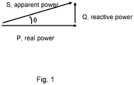
- AC power flow has two components, namely 1) real power (also called active power) (P), expressed in watts (W), and 2) reactive power (Q), usually expressed in reactive volt-amperes (VAR).
- P real power
- W watts
- Q reactive volt-amperes
- S complex power
- VA apparent power
- Figure 1 shows a vector power triangle to illustrate real power P, reactive power Q and apparent power S.
- the "power factor” is defined as the ratio of real power P to apparent power S. That is, the power factor describes the amount of real power transmitted along a transmission line relative to the total apparent power flowing in the line.
- Real power is the instantaneous product of voltage and current and represents the capacity of the electricity for performing work.
- Apparent power is the product of RMS current and voltage.
- the power factor is a dimensionless number in the range -1 to +1. A power factor of less than one indicates that the voltage and current are not in phase, which reduces the average product of the voltage and current.
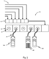
- FIG. 2 this shows schematically an example of a charging station 10 and a number of electric vehicles 100 being charged.
- Electrical energy is supplied from a mains electricity power grid, indicated schematically at 12.
- the electrical energy is supplied via a power factor measurement unit 14 to charger management units 16 which each have a charging socket 18 to which the vehicles 100 respectively connect using detachable charging cables 20.
- the power factor measurement unit 14 and the charger management units 16 are indicated as separate devices for measuring the power factor and controlling the charging of electric vehicles 100 respectively.
- the functionality of the power factor measurement unit 14 and the charger management units 16 may be provided by a single, combined unit.
- the power factor measurement unit 14 measures the real or active power P and the reactive power Q power of the mains electricity power grid 12.
- the power factor of the mains electricity power grid 12 is calculated as the ratio of real power P to apparent power S, where the apparent power S is the vector sum of the real power P and the reactive power Q with a phase angle ⁇ (see Figure 1 ).
- the power factor measurement unit 14 may calculate this power factor or it may be calculated by another unit. For example, national grid operators commonly monitor the power factor of a grid in order to ensure that it stays as close to 1 as possible, for the sake of efficient operation.
- the calculated power factor value is sent to the charger management units 16.
- the charger management units 16 control the charging of electric vehicles 100 based on at least the received power factor of the grid 12.
- the charging of electric vehicles 100 is controlled in order to keep the power factor high (i.e. close to 1). This may be achieved by for example limiting the charging of some electric vehicles 100 at any particular time. This is contrasted with for example allowing each electric vehicle 100 to draw power "at will" based only on considerations relevant for each electric vehicle independently (for example, in accordance only with the state of charge of the battery or batteries of that electric vehicle 100, the acceptable rate of delivery of electrical energy for that particular vehicle 100 based on its battery technology, etc.).
- This process of measuring the real power P and the reactive power Q power of the mains electricity power grid 12 and calculating (measuring) the power factor of the grid 12, and sending that power factor to the charger management units 16, may be carried out continuously or repeatedly at intervals of time (for example, once a minute, once every 5 minutes, once every 10 minutes, etc.). This enables the power factor that is used by the charger management units 16 to reflect closely the current instantaneous power factor of the grid 12, which enables better control of the power factor of the grid 12 by adjusting the charging of the electric vehicles 100 as necessary in more or less real time.
- a first criterion is that if the power factor of the grid 12 is already high, then all electric vehicles 100 that are connected to charging sockets 18 of the charging station 10 can be charged. Accordingly, if the power factor of the grid 12 is above some defined threshold, then the charger management units 16 can cause each connected electric vehicle 100 to be charged.
- the threshold for the power factor for this may be fixed or may be changed from time to time, according to for example local conditions, expected instantaneous demand on the power grid as a whole, etc. Further, what is regarded as an acceptable power factor for a grid may be different in different countries and different regions within a country. For example, a higher threshold, such as above 0.9, might be expected in some highly developed countries, whereas a lower threshold, such as above 0.75, might be tolerated in less developed countries.
- Another factor that may be used is to allocate a priority to the different electric vehicles 100. If for example the power factor falls below a threshold, then the charger management units 16 can cause only higher priority vehicles 100 to be charged, whilst other, lower priority vehicles 100 will not be charged (at least for the period of time whilst the power factor remains below that threshold). There may be several thresholds or ranges for the power factor and a corresponding allocation of different priorities to the vehicles 100. In this case, if the power factor is below a lowest threshold priority, only the highest priority vehicles 100 are charged; if the power factor is above a lowest threshold priority but below the next threshold, then vehicles having the highest priority and the next highest priority will be charged, but other, lower priority vehicles are not charged; etc.
- the priority that is allocated to an electric vehicle 100 may be based on one or more factors. Some examples will now be given.
- a first factor is the type of vehicle 100.
- the corresponding charger management unit 16 may obtain data from the vehicle 100 that indicates the type of vehicle 100. This data may be obtained via data lines associated with the charging cable 20, wirelessly from the electric vehicle 100, via software (an "app") which the driver of the vehicle 100 has installed on a personal computing device and that is registered with the operator of the charging station 100, etc.
- the data may indicate that the vehicle 100 is to be regarded as a high priority.
- the data may be encrypted to prevent "spoofing" of the type of vehicle 100 and therefore its priority.
- emergency vehicles such as ambulances, fire engines and the like, police and other state or government vehicles, etc.
- the vehicle 100 may indicate its "type" (i.e. that is one of a number of specific categories of vehicle) and the charger management unit 16 allocates a priority to the vehicle 100 based on that indicated type, or equivalently the vehicle 100 may indicate a priority directly and the charger management unit 16 allocates a charging priority to the vehicle 100 accordingly. If the vehicle 100 is not a high priority vehicle, such as an emergency vehicle, etc., or does not indicate its type, then the vehicle may be given a low priority.
- electric vehicles that are fully electric may be given a higher priority for charging than hybrid vehicles, given that hybrid vehicles already have another power source in the form of a combustion engine.
- electric vehicles that consume electrical energy at a low rate may be given a higher priority than electric vehicles that consume electrical energy at a high rate.
- a different priority may be allocated to two wheel electric vehicles, four wheel electric vehicles that have a low power rating, four wheel electric vehicles that have a high power rating, etc.
- electric vehicles that are four-wheel drive and or more suited for off-road driving, such as "sports utility vehicles" and the like may have a higher priority.
- electric lorries or trucks may have a higher priority as these may be deemed more important in order to ensure that food and other essential supplies are delivered.
- Another factor is the current state of charge of the battery or batteries of the electric vehicle 100.
- the corresponding charger management unit 16 may obtain data from the vehicle 100 that indicates the current state of charge of the battery or batteries of the electric vehicle 100. This data may for example be obtained via data lines associated with the charging cable 20 or wirelessly from the electric vehicle 100. If the current state of charge is low, then the vehicle 100 is treated as a high priority for charging. There may be different levels of priority corresponding to different levels of current state of charge.
- a priority table which may be used as a look-up table, may be in the following form, where a smaller number priority is a higher priority): Table 1 Priority Level Priority Rank Factors 1 Highest Emergency and state vehicles (ambulances, fire engines, police vehicles, etc.) 2 High Full EVs which have less than 10% current state of charge and less than 20% charge demand (i.e. demand an additional charge amount that is 20% of the battery capacity) 3 Medium Full EVs which have less than 50% current state of charge and less than 20% charge demand 4 Low Hybrid EVs which have less than 50% current state of charge and less than 20% charge demand
- a priority table which may be used as a look-up table, may be in the following form, where again a smaller number priority is a higher priority): Table 2 Priority Level Priority Rank Factors 1 Highest Emergency and state vehicles (ambulances, fire engines, police vehicles, etc.) 2 Two wheel full EVs which have less than 10% current state of charge and less than 20% charge demand 3 Four wheel full EVs which have less than 10% current state of charge and less than 20% charge demand 4 Two wheel full EVs which have less than 50% current state of charge and less than 20% charge demand 5 Four wheel full EVs which have less than 50% current state of charge and less than 20% charge demand 6 Lowest Hybrid EVs which have less than 50% current state of charge and less than 20% charge demand
- the factors that determine the priorities may be adjusted, based on for example current conditions of the grid 12, numbers and types of vehicles 100 typically using the charging station 10 at a particular time or at the current time, user preferences (which may be collated via questionnaires, social media), etc.
- the number of priorities in the tables above is four and six respectively, but this may also be adjusted, and the number of priorities may be different in different countries or regions according to local requirements.
- this shows schematically a flow diagram of an example of prioritising the charging of electric vehicles 100 at a charging station 10.
- the process may start at S1, for example when an electric vehicle 100 connects to a charging socket 18 of the charging station 10. Data concerning the type of vehicle and the state of charge of any connected electric vehicles 100 is obtained, and priorities are allocated to the electric vehicles 100 as discussed above.
- the priority table contains information concerning the priority of each electric vehicle 100 and the particular charging socket 18 to which the electric vehicle 100 is connected.
- the charger management units 16 control the charging of electric vehicles 100 such that all electric vehicles 100, that is all electric vehicles 100 having a priority of 1, 2, 3 or 4, are charged at S4.
- the charger management units 16 control the charging of electric vehicles 100 such that only the highest priority electric vehicles 100 are charged at S6 (in this example, only electric vehicles 100 having a priority of 1 or 2).
- the charger management units 16 may control the charging of electric vehicles 100 such that only electric vehicles 100 having the highest priority of 1 are charged. Then, when the power factor rises above the threshold, the charger management units 16 may control the charging of electric vehicles 100 such that again electric vehicles 100 having the two highest priorities of 1 and 2 are charged. Following that, if on the next iteration the power factor remains above the threshold, then the charger management units 16 may control the charging of electric vehicles 100 such that all electric vehicles 100 having a priority of 1, 2, 3 or 4 are charged. This can help to minimise the time that vehicle owners have to wait before their vehicle is charged, whilst prioritising important vehicles and yet keeping the power factor of the grid 12 high.
- the system may be arranged such that if the power factor of the grid 12 falls below some lowest threshold, such as for example 0.1 or similar, then no charging of any electric vehicle 100 is performed until the power factor rises above that lowest threshold again.
- the power factor measurement unit 14 for measuring the power factor of the grid 12 and the charger management units 16 may be provided separately or the functionality of the power factor measurement unit 14 and the charger management units 16 may be provided by a single, combined unit.
- FIG 4 shows schematically a block diagram of an example of a combined power factor measurement and charger management unit 200 of a charging station 10. The principal components of the combined unit 200 will be described. It will be understood that similar or corresponding components will be provided respectively in the power factor measurement units 14 and charger management units 16 of the previous example where these are provided separately.
- the unit 200 has a voltage measurement device 202 and a current measurement device 204 which are connected in use to the mains grid power supply 12 to measure the mains voltage and current respectively.
- the mains grid power supply 12 provides electrical energy to the sockets 18 of the charging station 100.
- the measurements of the mains voltage and current are provided to a processor 206 which calculates the power factor of the grid 12.
- a mains leakage current device 208 may measure mains leakage from the mains grid power supply 12.
- the sockets 18 of the charging station 100 are connected to a CP-PP control 210 and an interlock control 212.
- the CP-PP control 210 may be used to provide capability and performance indicators for the process as a whole.
- the interlock control 212 determines whether a charging cable 20 is connected to a particular charging socket 18 and provide a corresponding signal to charger routine software 214 which is being run by the processor 206.
- the processor 206 also runs software to implement a priority algorithm 216 which allocates priorities to the electric vehicles 100 and prioritises the charging of electric vehicles 100 in accordance with any of the examples discussed above. As discussed above in more detail above, in examples electric vehicles 100 may be charged or not at a particular time, under control of the processor 206 running the priority algorithm 216, depending particularly on the (instantaneous) power factor of the grid 12 and also the priorities that are allocated to the vehicles 100.
- the unit 200 has a memory block 218 which receives, from the electric vehicles 100 that are connected to charging sockets 18 at a particular time, data concerning those electric vehicles 100 and stores that data (at least temporarily for use in the necessary processing).
- the data may be received via wired and/or wireless connections, indicated schematically by an Ethernet and WiFi module 220, a GSM (Group Special Mobile) or other cellular (e.g. 3G, 4G, etc.) module 222 and an RFID/NFC (radio frequency identification/ near-field communication) module 224.
- the data concerning the electric vehicles 100 may include the type of vehicle 100 (e.g.
- the data concerning the electric vehicles 100 may include the current state of charge of the battery or batteries of the electric vehicles 100.
- the memory block 218 may also receive other data that is used to allocate priorities to the electric vehicles 100, including for determining the number of priorities to be allocated and the specific categories of vehicles 100 that are to be allocated a respective priority.
- data is indicated schematically at 226 as including social media information, information concerning electric vehicles from manufacturers of the electric vehicles, government regulations, which may for example stipulate how electric vehicle are to be prioritised for charging, IEC or similar Standards information, which again may stipulate how electric vehicle are to be prioritised for charging, etc.
- the unit 200 has a signal output device 228 which outputs a signal to contactors 230 which are connected to the mains power supply to each of the charging sockets 18.
- the signal output device 228 outputs signals to the respective contactors 230 which determine whether the electric vehicle 100 that is connected to the corresponding charging socket 18 is actually charged or not at any particular time, in accordance with the decision of the processor 206 based on the power factor of the grid 12 and the priorities of the electric vehicles 100, as discussed more fully above.
- Examples described herein whether implemented by separate devices or a combined unit, enable electric vehicles to be charged without jeopardising the operation of the mains electricity power grid.
- the examples can be integrated easily into existing charging stations and do not require high computing ability.
- the system can be adapted easily according to local requirements in different countries or regions, with simple and quick adaptation of the variables and factors that are used to determine which electric vehicles can be charged at any particular time.
- processor or processing system or circuitry referred to herein may in practice be provided by a single chip or integrated circuit or plural chips or integrated circuits, optionally provided as a chipset, an application-specific integrated circuit (ASIC), field-programmable gate array (FPGA), digital signal processor (DSP), graphics processing units (GPUs), etc.
- the chip or chips may comprise circuitry (as well as possibly firmware) for embodying at least one or more of a data processor or processors, a digital signal processor or processors, baseband circuitry and radio frequency circuitry, which are configurable so as to operate in accordance with the exemplary embodiments.
- the exemplary embodiments may be implemented at least in part by computer software stored in (non-transitory) memory and executable by the processor, or by hardware, or by a combination of tangibly stored software and hardware (and tangibly stored firmware).
- Suitable devices include for example a hard disk and non-volatile semiconductor memory (including for example a solid-state drive or SSD).
- the invention also extends to computer programs, particularly computer programs on or in a carrier, adapted for putting the invention into practice.
- the program may be in the form of non-transitory source code, object code, a code intermediate source and object code such as in partially compiled form, or in any other non-transitory form suitable for use in the implementation of processes according to the invention.
- the carrier may be any entity or device capable of carrying the program.
- the carrier may comprise a storage medium, such as a solid-state drive (SSD) or other semiconductor-based RAM; a ROM, for example a CD ROM or a semiconductor ROM; a magnetic recording medium, for example a floppy disk or hard disk; optical memory devices in general; etc.
- SSD solid-state drive
- ROM read-only memory
- magnetic recording medium for example a floppy disk or hard disk
- optical memory devices in general etc.
Landscapes
- Engineering & Computer Science (AREA)
- Power Engineering (AREA)
- Transportation (AREA)
- Mechanical Engineering (AREA)
- Charge And Discharge Circuits For Batteries Or The Like (AREA)
Priority Applications (1)
| Application Number | Priority Date | Filing Date | Title |
|---|---|---|---|
| EP21165007.2A EP4064497A1 (de) | 2021-03-25 | 2021-03-25 | Verfahren und vorrichtung zur steuerung des ladevorgangs von elektrofahrzeugen |
Applications Claiming Priority (1)
| Application Number | Priority Date | Filing Date | Title |
|---|---|---|---|
| EP21165007.2A EP4064497A1 (de) | 2021-03-25 | 2021-03-25 | Verfahren und vorrichtung zur steuerung des ladevorgangs von elektrofahrzeugen |
Publications (1)
| Publication Number | Publication Date |
|---|---|
| EP4064497A1 true EP4064497A1 (de) | 2022-09-28 |
Family
ID=75252292
Family Applications (1)
| Application Number | Title | Priority Date | Filing Date |
|---|---|---|---|
| EP21165007.2A Withdrawn EP4064497A1 (de) | 2021-03-25 | 2021-03-25 | Verfahren und vorrichtung zur steuerung des ladevorgangs von elektrofahrzeugen |
Country Status (1)
| Country | Link |
|---|---|
| EP (1) | EP4064497A1 (de) |
Citations (5)
| Publication number | Priority date | Publication date | Assignee | Title |
|---|---|---|---|---|
| WO2013032519A1 (en) * | 2011-09-02 | 2013-03-07 | Tesla Motors, Inc. | Multiport vehicle dc charging system with variable power distribution |
| WO2013100764A1 (en) * | 2011-12-29 | 2013-07-04 | Abb B.V. | Method, system and charger for charging a battery of an electric vehicle |
| US20130257146A1 (en) * | 2012-04-03 | 2013-10-03 | Geraldo Nojima | Electric vehicle supply equipment for electric vehicles |
| WO2018193091A1 (de) * | 2017-04-21 | 2018-10-25 | Wobben Properties Gmbh | Verfahren zum betreiben einer ladestation |
| KR20190131392A (ko) * | 2018-05-16 | 2019-11-26 | 한전케이디엔주식회사 | 전기차 충전기 계통 연계 단말장치 및 계통 연계 방법 |
-
2021
- 2021-03-25 EP EP21165007.2A patent/EP4064497A1/de not_active Withdrawn
Patent Citations (5)
| Publication number | Priority date | Publication date | Assignee | Title |
|---|---|---|---|---|
| WO2013032519A1 (en) * | 2011-09-02 | 2013-03-07 | Tesla Motors, Inc. | Multiport vehicle dc charging system with variable power distribution |
| WO2013100764A1 (en) * | 2011-12-29 | 2013-07-04 | Abb B.V. | Method, system and charger for charging a battery of an electric vehicle |
| US20130257146A1 (en) * | 2012-04-03 | 2013-10-03 | Geraldo Nojima | Electric vehicle supply equipment for electric vehicles |
| WO2018193091A1 (de) * | 2017-04-21 | 2018-10-25 | Wobben Properties Gmbh | Verfahren zum betreiben einer ladestation |
| KR20190131392A (ko) * | 2018-05-16 | 2019-11-26 | 한전케이디엔주식회사 | 전기차 충전기 계통 연계 단말장치 및 계통 연계 방법 |
Similar Documents
| Publication | Publication Date | Title |
|---|---|---|
| CN113401007B (zh) | 电力管理装置以及电力管理方法 | |
| KR101297079B1 (ko) | 중앙제어기반의 전기 자동차 충전 시스템, 및 중앙제어기반 전기자동차 충전시스템의 에너지 관리 방법 | |
| US20110084664A1 (en) | Method and apparatus of stored energy management in battery powered vehicles | |
| US8278881B2 (en) | Power grid load management for plug-in vehicles | |
| US20120200260A1 (en) | System for electric grid balancing and method of using and providing the same | |
| CN113232546A (zh) | 一种功率智能分配充电系统及控制方法 | |
| CN106887086A (zh) | 移动充电设备、移动充电系统及移动充电方法 | |
| KR101934938B1 (ko) | 충전 디바이스, 시스템, 및 충전 디바이스의 제어 방법 | |
| CN108258694B (zh) | 基于电力电子变压器的交直流微网协调控制方法 | |
| WO2015001775A1 (ja) | 電力管理システム、通知装置、制御装置、監視装置 | |
| CN210327150U (zh) | 一种基于共享充换电柜的5g基站供电系统 | |
| Zhao et al. | Future ultrafast charging stations for electric vehicles in China: charging patterns, grid impacts and solutions, and upgrade costs | |
| EP4064497A1 (de) | Verfahren und vorrichtung zur steuerung des ladevorgangs von elektrofahrzeugen | |
| CN103001272A (zh) | 具有电度计量和电池管理的充电站 | |
| US20240391349A1 (en) | Minimum Cost Demand Charge Management By Electric Vehicles | |
| CN118061812A (zh) | 工程机械充电装置及电动工程机械 | |
| US20240116385A1 (en) | Systems and methods for state of charge (soc)-based activation and control | |
| CN202888868U (zh) | 具有电度计量和电池管理的充电站装置 | |
| CN114759661A (zh) | 充换电模型的建立方法、装置和计算机设备 | |
| TR2021005426A2 (tr) | Elektri̇kli̇ araçlarin şarjini kontrol etme yöntemi̇ ve aparati | |
| CN116985663B (zh) | 基于光储充放的多目标直流柔性充电管理方法及装置 | |
| Quan-Do et al. | Monitoring of power allocation in centralized electric vehicle charging spot system | |
| US20250153595A1 (en) | Method and system of charging electric vehicle in an electric vehicle charging station | |
| JP7827923B1 (ja) | 充電システム、充電方法及び管理サーバ | |
| US20250337246A1 (en) | Balance control generator |
Legal Events
| Date | Code | Title | Description |
|---|---|---|---|
| PUAI | Public reference made under article 153(3) epc to a published international application that has entered the european phase |
Free format text: ORIGINAL CODE: 0009012 |
|
| STAA | Information on the status of an ep patent application or granted ep patent |
Free format text: STATUS: THE APPLICATION HAS BEEN PUBLISHED |
|
| AK | Designated contracting states |
Kind code of ref document: A1 Designated state(s): AL AT BE BG CH CY CZ DE DK EE ES FI FR GB GR HR HU IE IS IT LI LT LU LV MC MK MT NL NO PL PT RO RS SE SI SK SM TR |
|
| STAA | Information on the status of an ep patent application or granted ep patent |
Free format text: STATUS: THE APPLICATION IS DEEMED TO BE WITHDRAWN |
|
| 18D | Application deemed to be withdrawn |
Effective date: 20230329 |