EP4064510A1 - Battery charging control method and device - Google Patents
Battery charging control method and device Download PDFInfo
- Publication number
- EP4064510A1 EP4064510A1 EP21868411.6A EP21868411A EP4064510A1 EP 4064510 A1 EP4064510 A1 EP 4064510A1 EP 21868411 A EP21868411 A EP 21868411A EP 4064510 A1 EP4064510 A1 EP 4064510A1
- Authority
- EP
- European Patent Office
- Prior art keywords
- battery
- sampling
- fitting curve
- voltage
- condition
- Prior art date
- Legal status (The legal status is an assumption and is not a legal conclusion. Google has not performed a legal analysis and makes no representation as to the accuracy of the status listed.)
- Granted
Links
Images

Classifications
-
- H—ELECTRICITY
- H02—GENERATION; CONVERSION OR DISTRIBUTION OF ELECTRIC POWER
- H02J—ELECTRIC POWER NETWORKS; CIRCUIT ARRANGEMENTS OR SYSTEMS FOR SUPPLYING OR DISTRIBUTING ELECTRIC POWER; SYSTEMS FOR STORING ELECTRIC ENERGY
- H02J7/00—Circuit arrangements for charging or discharging batteries or for supplying loads from batteries
- H02J7/50—Circuit arrangements for charging or discharging batteries or for supplying loads from batteries acting upon multiple batteries simultaneously or sequentially
-
- H—ELECTRICITY
- H02—GENERATION; CONVERSION OR DISTRIBUTION OF ELECTRIC POWER
- H02J—ELECTRIC POWER NETWORKS; CIRCUIT ARRANGEMENTS OR SYSTEMS FOR SUPPLYING OR DISTRIBUTING ELECTRIC POWER; SYSTEMS FOR STORING ELECTRIC ENERGY
- H02J7/00—Circuit arrangements for charging or discharging batteries or for supplying loads from batteries
- H02J7/60—Circuit arrangements for charging or discharging batteries or for supplying loads from batteries including safety or protection arrangements
- H02J7/61—Circuit arrangements for charging or discharging batteries or for supplying loads from batteries including safety or protection arrangements against overcharge
-
- H—ELECTRICITY
- H02—GENERATION; CONVERSION OR DISTRIBUTION OF ELECTRIC POWER
- H02J—ELECTRIC POWER NETWORKS; CIRCUIT ARRANGEMENTS OR SYSTEMS FOR SUPPLYING OR DISTRIBUTING ELECTRIC POWER; SYSTEMS FOR STORING ELECTRIC ENERGY
- H02J7/00—Circuit arrangements for charging or discharging batteries or for supplying loads from batteries
- H02J7/90—Regulation of charging or discharging current or voltage
- H02J7/96—Regulation of charging or discharging current or voltage in response to battery voltage
- H02J7/963—Regulation of charging or discharging current or voltage in response to battery voltage in response to battery voltage gradient
-
- G—PHYSICS
- G01—MEASURING; TESTING
- G01R—MEASURING ELECTRIC VARIABLES; MEASURING MAGNETIC VARIABLES
- G01R31/00—Arrangements for testing electric properties; Arrangements for locating electric faults; Arrangements for electrical testing characterised by what is being tested not provided for elsewhere
- G01R31/36—Arrangements for testing, measuring or monitoring the electrical condition of accumulators or electric batteries, e.g. capacity or state of charge [SoC]
- G01R31/3644—Constructional arrangements
- G01R31/3648—Constructional arrangements comprising digital calculation means, e.g. for performing an algorithm
-
- G—PHYSICS
- G01—MEASURING; TESTING
- G01R—MEASURING ELECTRIC VARIABLES; MEASURING MAGNETIC VARIABLES
- G01R31/00—Arrangements for testing electric properties; Arrangements for locating electric faults; Arrangements for electrical testing characterised by what is being tested not provided for elsewhere
- G01R31/36—Arrangements for testing, measuring or monitoring the electrical condition of accumulators or electric batteries, e.g. capacity or state of charge [SoC]
- G01R31/382—Arrangements for monitoring battery or accumulator variables, e.g. SoC
- G01R31/3835—Arrangements for monitoring battery or accumulator variables, e.g. SoC involving only voltage measurements
-
- H—ELECTRICITY
- H01—ELECTRIC ELEMENTS
- H01M—PROCESSES OR MEANS, e.g. BATTERIES, FOR THE DIRECT CONVERSION OF CHEMICAL ENERGY INTO ELECTRICAL ENERGY
- H01M10/00—Secondary cells; Manufacture thereof
- H01M10/42—Methods or arrangements for servicing or maintenance of secondary cells or secondary half-cells
- H01M10/44—Methods for charging or discharging
- H01M10/441—Methods for charging or discharging for several batteries or cells simultaneously or sequentially
-
- H—ELECTRICITY
- H01—ELECTRIC ELEMENTS
- H01M—PROCESSES OR MEANS, e.g. BATTERIES, FOR THE DIRECT CONVERSION OF CHEMICAL ENERGY INTO ELECTRICAL ENERGY
- H01M10/00—Secondary cells; Manufacture thereof
- H01M10/42—Methods or arrangements for servicing or maintenance of secondary cells or secondary half-cells
- H01M10/44—Methods for charging or discharging
- H01M10/443—Methods for charging or discharging in response to temperature
-
- H—ELECTRICITY
- H02—GENERATION; CONVERSION OR DISTRIBUTION OF ELECTRIC POWER
- H02J—ELECTRIC POWER NETWORKS; CIRCUIT ARRANGEMENTS OR SYSTEMS FOR SUPPLYING OR DISTRIBUTING ELECTRIC POWER; SYSTEMS FOR STORING ELECTRIC ENERGY
- H02J7/00—Circuit arrangements for charging or discharging batteries or for supplying loads from batteries
- H02J7/60—Circuit arrangements for charging or discharging batteries or for supplying loads from batteries including safety or protection arrangements
- H02J7/65—Circuit arrangements for charging or discharging batteries or for supplying loads from batteries including safety or protection arrangements against overtemperature
-
- H—ELECTRICITY
- H02—GENERATION; CONVERSION OR DISTRIBUTION OF ELECTRIC POWER
- H02J—ELECTRIC POWER NETWORKS; CIRCUIT ARRANGEMENTS OR SYSTEMS FOR SUPPLYING OR DISTRIBUTING ELECTRIC POWER; SYSTEMS FOR STORING ELECTRIC ENERGY
- H02J7/00—Circuit arrangements for charging or discharging batteries or for supplying loads from batteries
- H02J7/60—Circuit arrangements for charging or discharging batteries or for supplying loads from batteries including safety or protection arrangements
- H02J7/663—Circuit arrangements for charging or discharging batteries or for supplying loads from batteries including safety or protection arrangements using battery or load disconnect circuits
Definitions
- This application relates to the technical field of batteries, and in particular, to a battery charging control method and device.
- This application provides a battery charging control method and device to effectively control battery charging.
- this application provides a battery charging control method, including: obtaining voltages of N cells in an M th sampling period, where the M th sampling period includes K sampling moments, the N cells form a battery, and N, M, and K are positive integers; calculating a voltage of the battery at each sampling moment among the K sampling moments based on the obtained voltages; and stopping charging the battery when both a first condition and a second condition are satisfied, where, the first condition includes: the voltage of the battery increases monotonically in the M th sampling period; and the second condition includes: a trend of a fitting curve of the voltage of at least one cell among the N cells in the M th sampling period is non-rising.
- the charging of the battery is stopped in a case that, during charging, the voltage of the battery increases monotonically in the M th sampling period and that the trend of the fitting curve of the voltage of at least one cell in the M th sampling period is non-rising. Not only the change of the voltage of the battery in a sampling period is considered, but also the change of the voltage of the cell in the sampling period is considered.
- the charging of the battery can be stopped in time based on the voltage of the battery and the voltage of the cell when the change of the voltage is abnormal, thereby avoiding thermal runaway of the battery and effectively controlling the battery charging process.
- voltages of at least one cell among the N cells in P consecutive sampling periods after the M th sampling period in the second condition are obtained, and the P consecutive sampling periods and the M th sampling period constitute P+1 consecutive sampling periods, where P is a positive integer.
- the second condition further includes: the trend of the fitting curve of the voltage of the at least one cell among the N cells in each sampling period among the P consecutive sampling periods is non-rising.
- the voltage of the cell in a plurality of consecutive sampling periods is judged, thereby avoiding impact brought by accidental factors such as voltage fluctuations and further increasing accuracy of battery charging control.
- the fitting curve is a linear fitting curve
- that the trend of the fitting curve in the second condition is non-rising includes: a slope of the linear fitting curve is less than or equal to 0, and that the trend of the fitting curve is rising includes: the slope of the linear fitting curve is greater than 0; or, when the fitting curve is an exponential fitting curve or a logarithmic fitting curve, that the trend of the fitting curve is non-rising includes: a base of the exponential fitting curve or the logarithmic fitting curve is greater than 0 and less than or equal to 1, and that the trend of the fitting curve is rising includes: the base of the exponential fitting curve or the logarithmic fitting curve is greater than 1.
- the voltage of the battery increases monotonically in the M th sampling period specifically includes: a difference between the voltage of the battery at a (j+1) th sampling moment and the voltage of the battery at a j th sampling moment is greater than 0, where 1 ⁇ j ⁇ K-1.
- the calculating a voltage of the battery at each sampling moment among the K sampling moments specifically includes: summing the voltages of the N cells at an i th sampling moment to obtain the voltage of the battery at the i th sampling moment, where 1 ⁇ i ⁇ K.
- a current of the battery at each sampling moment among the K sampling moments is obtained.
- Charging of the battery is continued when both the first condition and a third condition are satisfied.
- the third condition includes: the trend of the fitting curve of the voltage of each of the N cells in the M th sampling period is rising.
- a current of the battery at each sampling moment among the K sampling moments is obtained. Charging of the battery is stopped when the first condition is not satisfied but a fourth condition is satisfied.
- the fourth condition includes: a difference between a preset current and the current of the battery at each sampling moment among the K sampling moments is less than a preset threshold.
- the preset current is a preset value of the battery in the M th sampling period.
- the battery charging process can be effectively controlled.
- the current of the battery at each sampling moment among the K sampling moments is obtained. Charging of the battery is stopped when the first condition is not satisfied but a fifth condition is satisfied.
- the fifth condition includes: a difference between a preset current and the current of the battery on at least one sampling moment among the K sampling moments is greater than a preset threshold.
- this application provides a battery charging control device.
- the device includes: an obtaining module, configured to obtain voltages of N cells in an M th sampling period.
- the M th sampling period includes K sampling moments, the N cells form a battery, and N, M, and K are positive integers.
- the obtaining module is further configured to calculate a voltage of the battery at each sampling moment among the K sampling moments based on the obtained voltages.
- the processing module is configured to stop charging the battery when both a first condition and a second condition are satisfied.
- the first condition includes: the voltage of the battery increases monotonically in the M th sampling period.
- the second condition includes: a trend of a fitting curve of the voltage of at least one cell among the N cells in the M th sampling period is non-rising.
- the processing module stops charging the battery in a case that, during charging, the voltage of the battery increases monotonically in the M th sampling period and that the trend of the fitting curve of the voltage of at least one cell in the M th sampling period is non-rising. Not only the change of the voltage of the battery in a sampling period is considered, but also the change of the voltage of the cell in the sampling period is considered.
- the charging of the battery can be stopped in time based on the voltage of the battery and the voltage of the cell when the change of the voltage is abnormal, thereby avoiding thermal runaway of the battery and effectively controlling the battery charging process.
- the obtaining module obtains voltages of at least one cell in P consecutive sampling periods after the M th sampling period.
- the P consecutive sampling periods and the M th sampling period constitute P+1 consecutive sampling periods, where P is a positive integer.
- the processing module is specifically configured to: stop charging the battery when both the first condition and the second condition are satisfied.
- the second condition further includes: the trend of the fitting curve of the voltage of the at least one cell among the N cells in each sampling period among the P consecutive sampling periods is non-rising.
- the processing module judges the voltage of the cell in a plurality of consecutive sampling periods, thereby avoiding impact brought by accidental factors such as voltage fluctuations and further increasing accuracy of battery charging control.
- the processing module stops charging the battery when both the first condition and the second condition are satisfied.
- the fitting curve in the second condition is a linear fitting curve
- that the trend of the fitting curve is non-rising includes: a slope of the linear fitting curve is less than or equal to 0, and that the trend of the fitting curve is rising includes: the slope of the linear fitting curve is greater than 0; or, when the fitting curve is an exponential fitting curve or a logarithmic fitting curve, that the trend of the fitting curve is non-rising includes: a base of the exponential fitting curve or the logarithmic fitting curve is greater than 0 and less than or equal to 1, and that the trend of the fitting curve is rising includes: the base of the exponential fitting curve or the logarithmic fitting curve is greater than 1.
- the processing module is configured to: determine, when a difference between the voltage of the battery at a (j+1) th sampling moment and the voltage of the battery at a j th sampling moment is greater than 0, that the voltage of the battery increases monotonically in the M th sampling period, where 1 ⁇ j ⁇ K-1.
- the obtaining module is specifically configured to sum the voltages of the N cells at each sampling moment among the K sampling moments to obtain the voltage of the battery at each sampling moment among the K sampling moments, where 1 ⁇ i ⁇ K.
- the obtaining module is further configured to obtain a current of the battery at each sampling moment among the K sampling moments.
- the processing module is further configured to: continue charging the battery when both the first condition and a third condition are satisfied.
- the third condition includes: the trend of the fitting curve of the voltage of each of the N cells in the M th sampling period is rising.
- the obtaining module is further configured to obtain a current of the battery at each sampling moment among the K sampling moments.
- the processing module is further configured to stop charging the battery when the first condition is not satisfied but a fourth condition is satisfied.
- the fourth condition includes: a difference between a preset current and the current of the battery at each sampling moment among the K sampling moments is less than a preset threshold, where the preset current is a preset value of the battery in the M th sampling period.
- the processing module When a charge current of the battery is switched, the voltage of the battery will also fluctuate accordingly due to electrochemical characteristics of the battery. If the processing module detects that the current of the battery is not switched and the voltage of the battery does not increase monotonically, the processing module stops charging the battery in a case of thermal runaway. By detecting the current of the battery obtained by the obtaining module, the processing module can effectively control the battery charging process.
- the processing module is configured to: continue charging the battery when the first condition is not satisfied but a fifth condition is satisfied.
- the fifth condition includes: a difference between a preset current and the current of the battery on at least one sampling moment among the K sampling moments is greater than a preset threshold.
- this application further provides a battery charging control method, including: obtaining voltages of N cells in an M th sampling period, where the sampling period includes K sampling moments, the N cells form a battery, and N, M, and K are positive integers; calculating a voltage of the battery at each sampling moment among the K sampling moments based on the obtained voltages; obtaining a current of the battery at each sampling moment among K sampling moments; and stopping charging the battery when a first condition is not satisfied but a fourth condition is satisfied.
- the first condition includes: the voltage of the battery increases monotonically in the M th sampling period.
- the fourth condition includes: a difference between a preset current and the current of the battery at each sampling moment among the K sampling moments is less than a preset threshold, where the preset current is a preset value of the battery in the M th sampling period.
- the charging of the battery is stopped in a case that, during charging, the voltage of the battery increases monotonically in the M th sampling period and that the trend of the fitting curve of the voltage of at least one cell in the M th sampling period is non-rising. Not only the change of the voltage of the battery in a sampling period is considered, but also the change of the voltage of the cell in the sampling period is considered.
- the charging of the battery can be stopped in time based on the voltage of the battery and the voltage of the cell when the change of the voltage is abnormal, thereby avoiding thermal runaway of the battery.
- the voltage of the battery will also fluctuate accordingly due to electrochemical characteristics of the battery. If the voltage of the battery does not increase monotonically and the current of the battery is not switched, the battery is at risk of thermal runaway in this case. By detecting the current of the battery, the battery charging process can be effectively controlled.
- the method includes: stopping charging the battery when the first condition is not satisfied but a fifth condition is satisfied.
- the fifth condition includes: a difference between a preset current and the current of the battery on at least one sampling moment among the K sampling moments is greater than a preset threshold.
- this application provides a battery charging control device, including: an obtaining module, configured to obtain voltages of N cells in an M th sampling period, where the M th sampling period includes K sampling moments, the N cells form a battery, and N, M, and K are positive integers; an obtaining module, configured to: calculate a voltage of the battery at each sampling moment among the K sampling moments based on the obtained voltages, and obtain a current of the battery at each sampling moment among K sampling moments; and a processing module, configured to stop charging the battery when a first condition is not satisfied but a fourth condition is satisfied, where the first condition includes: the voltage of the battery increases monotonically in the M th sampling period, and the fourth condition includes: a difference between a preset current and the current of the battery at each sampling moment among the K sampling moments is less than a preset threshold.
- the processing module stops charging the battery in a case that, during charging, the voltage of the battery increases monotonically in the M th sampling period and that the trend of the fitting curve of the voltage of at least one cell in the M th sampling period is non-rising. Not only the change of the voltage of the battery in a sampling period is considered, but also the change of the voltage of the cell in the sampling period is considered.
- the charging of the battery can be stopped in time based on the voltage of the battery and the voltage of the cell when the change of the voltage is abnormal, thereby avoiding thermal runaway of the battery. When a charge current of the battery is switched, the voltage of the battery will also fluctuate accordingly due to electrochemical characteristics of the battery.
- the processing module If the processing module detects that the current of the battery is not switched and the voltage of the battery does not increase monotonically, the processing module stops charging the battery in a case of thermal runaway. By detecting the current of the battery obtained by the obtaining module, the processing module can effectively control the battery charging process.
- the processing module is configured to: continue charging the battery when the first condition is not satisfied but a fifth condition is satisfied.
- the fifth condition includes: a difference between a preset current and the current of the battery on at least one sampling moment among the K sampling moments is greater than a preset threshold.
- a battery In an electric vehicle and an energy storage device, a battery is a source of power to the vehicle or the device.
- a power battery includes several cells connected in series and in parallel. Electrochemical performance of the power battery is complex and the number of cells is relatively large, a battery management system (Battery Management System, BMS) is required to serve as a link between the battery and a user, and serves to detect the entire battery and status parameters of the cells such as voltage, current, and temperature, and analyzes and judges detection data to improve a utilization rate of the battery, monitor usage status of the battery, prevent safety problems such as thermal runaway of the battery, and prolong a service life of the battery.
- BMS Battery Management System
- the battery management system can take corresponding measures against thermal runaway caused by overcharge. If abnormality such as a micro short circuit or a short circuit occurs inside a cell of the battery, thermal runaway of the battery may still occur during charging because sparks generated by the expansion and short circuit of the cell may instantly ignite an electrolytic solution inside the cell. For the thermal runaway that is not caused by overcharge, because the current, voltage, or temperature of the battery does not incur overcurrent, overvoltage, or overtemperature before the failure of the battery, the BMS is not triggered to handle thermal runaway.
- this application provides a battery charging control method and device, so that the BMS can effectively control the battery charging process in a case of no overcharge, and prevent thermal runaway of the battery.
- the battery in the embodiments of this application may be a battery in an energy storage device, or may be a power battery in an electric vehicle.
- the battery may be a lithium iron phosphate battery or a ternary battery, without being limited herein.
- the battery in the embodiments of this application includes N cells, where N is a positive integer.
- the cell may mean an electronic core or a battery module compounded of a plurality of cells connected in series, or the like.
- the N cells form a battery, and the battery may be formed by connecting a plurality of cells in series.
- the embodiments of this application do not limit the specific form of the cell.
- FIG. 1 is a schematic flowchart of a battery charging control method according to Embodiment 1 of this application. As shown in FIG. 1 , the battery charging control method according to this embodiment may include steps S 110 to S130.
- the BMS obtains a voltage of a cell through voltage sampling, and can obtain the voltages of the N cells concurrently at one sampling moment.
- One sampling period may include one or more sampling moments. That is, in a sampling period, such as the M th sampling period, the voltages of the N cells at K sampling moments in the sampling period can be obtained by sampling, where K is a positive integer.
- a battery includes N cells connected in series. Therefore, the voltage of the battery is a sum of the voltages of the N cells included in the battery.
- the BMS calculates and obtains the voltage of the battery at each sampling moment in the sampling period based on the voltage of each cell at each sampling moment among the K sampling moments in the M th sampling period.
- the voltages of the N cells at an i th sampling moment are summed to obtain the voltage of the battery at the i th sampling moment, where 1 ⁇ i ⁇ K.
- the first condition includes: the voltage of the battery increases monotonically in the M th sampling period.
- the second condition includes: a trend of a fitting curve of the voltage of at least one cell among the N cells in the M th sampling period is non-rising.
- the BMS obtains the voltages of the cells by sampling, and calculates the voltage of the battery in the sampling period.
- the BMS stops charging the battery if the voltage of the battery increases monotonically in the sampling period and a change trend of the voltage of at least one cell in the sampling period is non-rising.
- the BMS determines that the cell is at risk of thermal runaway, and marks the cell as an abnormal cell.
- the BMS determines that the voltage of the battery increases monotonically in the M th sampling period, where 1 ⁇ j ⁇ K-1.
- the BMS may perform fitting, such as linear fitting, exponential fitting, or logarithmic fitting, on the voltage of the cell in the M th sampling period. Based on characteristics of the fitting curve, the BMS obtains the change trend of the voltage of the cell in the sampling period.
- the BMS establishes a two-dimensional data group for each sampling moment in the M th sampling period and the voltage of the cell corresponding to the sampling moment, and solves the data group by a least square method to obtain a slope value of a linear regression equation of each cell in the sampling period.
- the slope value of the linear fitting curve of the cell is less than or equal to 0, it indicates that the trend of the linear fitting curve is unchanged or falling, that is, the trend of the linear fitting curve of the cell in the M th sampling period is non-rising.
- the slope value is greater than 0, the trend of the linear fitting curve of the cell in the M th sampling period is rising.
- the BMS establishes a two-dimensional data group for a sampling moment in the M th sampling period and the voltage of the cell corresponding to the sampling moment, and solves the data group by the least square method to obtain a base of an exponential regression equation of each cell in the sampling period.
- the base of the fitting curve of the cell is greater than 0 and less than or equal to 1, it indicates that the trend of the exponential fitting curve is unchanged or falling, that is, the trend of the exponential fitting curve of the cell in the M th sampling period is non-rising.
- the base of the exponential fitting curve of the cell is greater than 1, the trend of the exponential fitting curve of the cell in the M th sampling period is rising.
- the BMS establishes a two-dimensional data group for a sampling moment in the M th sampling period and the voltage of the cell corresponding to the sampling moment, and solves the data group by the least square method to obtain a base of a logarithmic regression equation of each cell.
- the base of the logarithmic fitting curve of the cell is greater than 0 and less than or equal to 1, it indicates that the trend of the logarithmic fitting curve is unchanged or falling, that is, the trend of the logarithmic fitting curve of the cell in the M th sampling period is non-rising.
- the base of the logarithmic fitting curve of the cell is greater than 1, the trend of the logarithmic fitting curve of the cell in the M th sampling period is rising.
- the charging of the battery is stopped if the trend of the fitting curve of the voltage of at least one cell in the M th sampling period is non-rising and the voltage of the battery increases monotonically in the M th sampling period.
- the BMS may perform fitting on the voltage of the at least one cell in each sampling period among a plurality of consecutive sampling periods.
- each sampling period includes K sampling moments.
- the trend of the fitting curve of the voltage of at least one cell among the N cells is obtained.
- the voltages of the at least one cell at each sampling moment in P consecutive sampling periods after the M th sampling period are obtained.
- the P consecutive sampling periods and the M th sampling period constitute P+1 consecutive sampling periods, where P is a positive integer.
- the charging of the battery is stopped if the voltage of the battery increases monotonically in the M th sampling period and the trend of the fitting curve of the voltage of the at least one cell among the N cells in each sampling period among the P+1 consecutive sampling periods is non-rising.
- P is equal to 2. That is, the voltage of the at least one cell is fitted in 3 consecutive sampling periods, thereby avoiding the impact caused by voltage fluctuations onto precision and simplifying the algorithm.
- the BMS judges the voltage of the battery in a plurality of consecutive sampling periods. In each of the M th sampling period, the (M+1) th sampling period, and so on, and the (M+P) th sampling period, the BMS obtains the voltage of the battery at each sampling moment.
- the BMS stops charging the battery if the voltage of the battery increases monotonically in each of the foregoing sampling periods and the trend of the fitting curve of the voltage of the at least one cell among the N cells of the battery in each sampling period among the P+1 consecutive sampling periods is non-rising. That is, the BMS stops charging the battery if, in each sampling period among the P+1 consecutive sampling periods, the voltage of the battery increases monotonically and the trend of the fitting curve of the voltage of at least one cell among the N cells of the battery is non-rising.
- the BMS may fit the voltage data of the cell linearly, logarithmically, or exponentially.
- the BMS may fit the voltage of the at least one cell in a plurality of consecutive sampling periods. Using the M th sampling period, the (M+1) th sampling period, and so on, and the (M+P) th sampling period as a combined sampling period, the BMS obtains the trend of the fitting curve of the voltage of the at least one cell in the combined sampling period. The BMS stops charging the battery if the voltage of the battery increases monotonically in the combined sampling period and the trend of the fitting curve of the voltage of at least one cell among the N cells in the combined sampling period is non-rising.
- P is equal to 2, thereby avoiding the impact caused by voltage fluctuations onto precision and simplifying the algorithm.
- the BMS continues charging the battery when both the first condition and a third condition are satisfied.
- the third condition includes: the trend of the fitting curve of the voltage of each of the N cells of the battery in the M th sampling period is rising.
- the BMS obtains the current of the battery at each sampling moment among the K sampling moments, and stops charging the battery when the first condition is not satisfied but a fourth condition is satisfied.
- the fourth condition includes: the difference between the preset current and the current of the battery at each sampling moment among the K sampling moments is less than the preset threshold.
- a battery charging method in this embodiment of this application is constant-current charging. That is, a charging process is divided into several charging stages, a charge current remains constant in each charging stage, and the voltage of the battery increases with time.
- the BMS stops charging the battery if the voltage of the battery drops in a sampling period, that is, the voltage does not increase monotonically, and if both the preset current and the current value of the battery at each sampling moment in the sampling period are less than a preset threshold, indicating that the battery is not switched to a next charging stage at this time.
- the voltage drop is an abnormal phenomenon, and leaves the battery to be at risk of thermal runaway.
- Both the preset current and the preset threshold are set by the BMS.
- the preset threshold may be 20% of the preset current.
- the fifth condition includes: a difference between a preset current and the current of the battery on at least one sampling moment among the K sampling moments is greater than a preset threshold.
- the battery includes 8 cells, and the sampling period includes 10 sampling moments. It is assumed that an interval between two adjacent sampling moments is 1 second. That is, the BMS obtains the voltage of the cell once every 1 second.
- the BMS samples the voltages of all cells at each sampling moment. For this sampling period, the BMS can obtain the voltage data of 8 cells at 10 sampling moments, expressed as follows:
- the first numeral represents a serial number of the cell
- the second numeral represents a sampling moment
- the BMS calculates the voltage of the battery at each sampling moment among 10 sampling moments based on the foregoing voltage data. That is, for the first sampling moment, the BMS sums V 1,1 , V 2,1 , ..., V 8,1 to obtain Vi, that is, the voltage of the battery at the first sampling moment. Similarly, the voltages of the battery, V 2 to V 10 , at remaining 9 sampling moments can be calculated.
- the BMS subtracts the voltage of the battery at a j h sampling moment from the voltage of the battery at a (j+1) th sampling moment (1 ⁇ j ⁇ 9) to obtain a difference. If the voltage difference between every two adjacent sampling moments is greater than 0, it is determined that the voltage of the battery increases monotonically in the sampling period.
- the BMS solves the data group Qi by the least square method to obtain a slope value of a linear regression equation, and similarly, obtain the slope value of the corresponding linear regression equation of each of the remaining 7 cells in the sampling period.
- the BMS determines that the battery is at risk of thermal runaway and stops charging the battery.
- the BMS may perform linear fitting on the voltage of the at least one cell in 3 consecutive sampling periods. Assuming that the slope value of the voltage fitting curve of the cell in 3 consecutive sampling periods is less than or equal to 0, the BMS determines that the battery is at risk of thermal runaway and stops charging the battery.
- a plurality of consecutive sampling periods for example, 3 consecutive sampling periods, may be judged.
- the processing of each of the plurality of consecutive sampling periods is the same as the processing of the foregoing one sampling period, and is omitted here.
- FIG. 2 is a schematic flowchart of a battery charging control method according to Embodiment 2 of this application; As shown in FIG. 2 , the battery charging control method according to this embodiment may include steps S210 to S240.
- step S 110 for the specific content of this step, reference may be made to the related description of step S 110 in Embodiment 1 of this application, and details are omitted here.
- a BMS calculates a voltage of a battery at each sampling moment among K sampling moments based on the voltages.
- step S120 for the specific content of this step, reference may be made to the related description of step S120 in Embodiment 1 of this application, and details are omitted here.
- the BMS obtains the current of the battery at each sampling moment in the M th sampling period.
- the first condition includes: the voltage of the battery increases monotonically in the M th sampling period.
- the fourth condition includes: a difference between a preset current in the M th sampling period and the current of the battery at each sampling moment among the K sampling moments is less than a preset threshold.
- a battery charging method in this embodiment of this application is constant-current charging. That is, a charging process is divided into several charging stages, a charge current remains constant in each charging stage, and the voltage of the battery increases with time.
- the BMS stops charging the battery if the voltage of the battery drops in a sampling period, that is, the voltage does not increase monotonically, and if both the preset current and the current value of the battery at each sampling moment in the sampling period are less than a preset threshold, indicating that the battery is not switched to a next charging stage at this time.
- the voltage drop is an abnormal phenomenon, and leaves the battery to be at risk of thermal runaway.
- Both the preset current and the preset threshold are set by the BMS.
- the preset threshold may be 20% of the preset current.
- the BMS may judge the current of the battery in each sampling period among a plurality of consecutive sampling periods. It needs to be noted that each sampling period includes K sampling moments. In each of the M th sampling period, the (M+1) th sampling period, and so on, and the (M+P) th sampling period, the BMS obtains the current of the battery. Specifically, the current of the battery at each sampling moment in P consecutive sampling periods after the M th sampling period is obtained.
- the P consecutive sampling periods and the M th sampling period constitute P+1 consecutive sampling periods, where P is a positive integer.
- the BMS stops charging the battery.
- P is equal to 2. That is, the BMS obtains the current of the battery in 3 consecutive sampling periods, calculates the difference between the preset current and the current of the battery at each sampling moment, and compares the difference with the preset threshold, thereby avoiding the impact caused by voltage fluctuations onto precision and simplifying the algorithm.
- the BMS may judge the current of the battery in a plurality of consecutive sampling periods. Using the M th sampling period, the (M+1) th sampling period, and so on, and the (M+P) th sampling period as a combined sampling period, the BMS obtains a difference between the preset current and the current of the battery at each sampling moment in the combined sampling period. If the voltage of the battery increases monotonously in the combined sampling period, and the difference is less than the preset threshold, the BMS stops charging the battery.
- P is equal to 2, thereby avoiding the impact caused by current fluctuations onto precision and simplifying the algorithm.
- the BMS continues charging the battery when the first condition is not satisfied but a fifth condition is satisfied.
- the fifth condition includes: a difference between a preset current in the M th sampling period and the current of the battery on at least one sampling moment among the K sampling moments is greater than a preset threshold.
- FIG. 3 is a schematic structural diagram of a battery charging control device according to Embodiment 3 of this application;
- the battery charging control device 300 includes an obtaining module 310 and a processing module 320.
- the battery charging control device 300 in this embodiment of this application may be a device that possesses independent functions, or may be integrated in a BMS, without being limited herein.
- the obtaining module 310 is configured to obtain voltages of N cells in an M th sampling period.
- the obtaining module 310 obtains a voltage of a cell, and can obtain the voltages of the N cells of the battery concurrently at one sampling moment.
- One sampling period may include one or more sampling moments. That is, in a sampling period, such as the M th sampling period, the voltages of the N cells at K sampling moments in the sampling period can be obtained by sampling, where K is a positive integer.
- the obtaining module 310 is further configured to calculate a voltage of the battery at each sampling moment among the K sampling moments based on the voltages.
- a battery includes N cells connected in series. Therefore, the voltage of the battery is a sum of the voltages of the N cells included in the battery.
- the obtaining module 310 calculates and obtains the voltage of the battery at each sampling moment in the sampling period based on the voltage of each cell at each sampling moment among the K sampling moments in the M th sampling period.
- the obtaining module 310 is configured to sum the voltages of the N cells at an i th sampling moment to obtain the voltage of the battery at the i th sampling moment, where 1 ⁇ i ⁇ K.
- the processing module 320 is configured to stop charging the battery when both a first condition and a second condition are satisfied.
- the first condition includes: the voltage of the battery increases monotonically in the M th sampling period.
- the second condition includes: a trend of a fitting curve of the voltage of at least one cell among the N cells in the M th sampling period is non-rising.
- the voltage of the battery is calculated based on the voltages of the cells inside the battery.
- the voltage of the battery increases monotonically in a sampling period, if the change trend of the voltage of some cells in the sampling period is non-rising, a possible reason is that a short circuit occurs inside such cells.
- the voltage of each cell is fitted to obtain a fitting curve to detect the change trend of the voltage.
- a battery charging circuit is cut off to stop charging the battery, thereby effectively control the battery charging process.
- the processing module 320 is further configured to judge a difference between the voltage of the battery at a (j+1) th sampling moment and the voltage of the battery at a j th sampling moment. If the difference is greater than 0 throughout the M th sampling period, the processing module 320 determines that the voltage of the battery increases monotonically in the M th sampling period, where 1 ⁇ j ⁇ K-1.
- the processing module 320 may perform fitting, such as linear fitting, exponential fitting, or logarithmic fitting, on the voltage of the cell in the M th sampling period.
- the processing module 320 Based on characteristics of the fitting curve, the processing module 320 obtains the change trend of the voltage of the cell in the sampling period.
- the processing module 320 makes a judgment, and stops charging the battery if the trend of the fitting curve of the voltage of at least one cell in the M th sampling period is non-rising and the voltage of the battery increases monotonically in the M th sampling period.
- the processing module 320 may fit the voltage of the at least one cell in a plurality of consecutive sampling periods.
- P is equal to 2. That is, the processing module 320 fits the voltage of the at least one cell in 3 consecutive sampling periods, thereby avoiding the impact caused by voltage fluctuations onto precision and simplifying the algorithm.
- the processing module 320 may fit the voltage data of the cell linearly, logarithmically, or exponentially.
- the processing module 320 may be configured to fit the voltage of the at least one cell in a plurality of consecutive sampling periods. Using the M th sampling period, the (M+1) th sampling period, and so on, and the (M+P) th sampling period as a combined sampling period, the processing module obtains the trend of the fitting curve of the voltage of the at least one cell in the combined sampling period.
- the processing module stops charging the battery if the voltage of the battery increases monotonically in the combined sampling period and the trend of the fitting curve of the voltage of at least one cell among the N cells in the combined sampling period is non-rising.
- the obtaining module 310 is further configured to obtain a current of the battery at each sampling moment among the K sampling moments.
- the processing module 320 is further configured to: when the first condition and a third condition are satisfied, determine that the battery is normal, and continue charging the battery, where the third condition includes: the trend of the fitting curve of the voltage of the N cells of the battery in the M th sampling period is rising.
- the obtaining module 310 is further configured to obtain the current of the battery at each sampling moment among the K sampling moments.
- the processing module 320 is further configured to stop charging the battery when the first condition is not satisfied but a fourth condition is satisfied.
- the fourth condition includes: a difference between a preset current in the M th sampling period and the current of the battery at each sampling moment among the K sampling moments is less than a preset threshold.
- FIG. 4 is a schematic structural diagram of a battery charging control device according to Embodiment 4 of this application.
- the battery charging control device 400 includes an obtaining module 410 and a processing module 420.
- the obtaining module 410 is configured to obtain voltages of N cells in an M th sampling period.
- the obtaining module 410 obtains a voltage of a cell through voltage sampling, and can obtain the voltages of the N cells of the battery concurrently at one sampling moment.
- One sampling period may include one or more (K) sampling moments. That is, in a sampling period, such as the M th sampling period, the voltages of the N cells at each sampling moment can be obtained by sampling.
- the obtaining module 410 is further configured to calculate a voltage of the battery at each sampling moment among the K sampling moments based on the voltages.
- a battery includes N cells. Therefore, the voltage of the battery is a sum of the voltages of the N cells included in the battery.
- the obtaining module 410 calculates and obtains the voltage of the battery at each sampling moment in the sampling period based on the voltage of each cell at each sampling moment in the M th sampling period.
- the obtaining module 410 is configured to sum the voltages of the N cells at an i th sampling moment to obtain the voltage of the battery at the i th sampling moment, where 1 ⁇ i ⁇ K.
- the obtaining module 410 is further configured to obtain a current of the battery at each sampling moment among the K sampling moments.
- the processing module 420 is configured to stop charging the battery when a first condition is not satisfied but a fourth condition is satisfied.
- the first condition includes: the voltage of the battery increases monotonically in the M th sampling period.
- the fourth condition includes: a difference between a preset current in the M th sampling period and the current of the battery at each sampling moment among the K sampling moments is less than a preset threshold.
- a battery charging method in this embodiment of this application is constant-current charging. That is, a charging process is divided into several charging stages, a charge current remains constant in each charging stage, and the voltage of the battery increases with time.
- the battery charging control device stops charging the battery if the voltage of the battery drops in a sampling period, that is, the voltage does not increase monotonically, and if both the preset current and the current value of the battery at each sampling moment in the sampling period are less than a preset threshold, indicating that the battery is not switched to a next charging stage at this time.
- the voltage drop is an abnormal phenomenon, and leaves the battery to be at risk of thermal runaway.
- Both the preset current and the preset threshold are set by the battery charging control device 400.
- the preset threshold may be 20% of the preset current.
- the processing module 420 may judge the current of the battery obtained by the obtaining module 410 in each sampling period among a plurality of consecutive sampling periods. It needs to be noted that each sampling period includes K sampling moments.
- the processing module 420 is further configured to make a judgment, and continue charging the battery when the first condition is not satisfied but a fifth condition is satisfied.
- the fifth condition includes: a difference between a preset current in the M th sampling period and the current of the battery on at least one sampling moment among the K sampling moments is greater than a preset threshold.
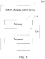
- FIG. 5 is a schematic structural diagram of a battery charging control device according to Embodiment 5 of this application.
- the battery charging control device 500 includes a memory 510 and a processor 520.
- the memory 510 is configured to store an instruction.
- the processor 520 is configured to perform the battery charging control method based on the instruction.
- a readable storage medium is further provided in an embodiment of this application, and is configured to store a computer program.
- the computer program is configured to perform the battery charging control method.
- a plurality of referred to in this application means two or more (including two).
- a plurality of groups means two or more groups (including two groups)
- a plurality of pieces means two or more pieces (including two pieces).
Landscapes
- Engineering & Computer Science (AREA)
- Power Engineering (AREA)
- Manufacturing & Machinery (AREA)
- Chemical & Material Sciences (AREA)
- Chemical Kinetics & Catalysis (AREA)
- Electrochemistry (AREA)
- General Chemical & Material Sciences (AREA)
- Physics & Mathematics (AREA)
- General Physics & Mathematics (AREA)
- Secondary Cells (AREA)
- Charge And Discharge Circuits For Batteries Or The Like (AREA)
Abstract
Description
- This application claims priority to
Chinese Patent Application No. 2020109871569, filed on September 18, 2019 - This application relates to the technical field of batteries, and in particular, to a battery charging control method and device.
- With the development of new energy, new energy is used as power in more fields. Power batteries are widely used in new-energy battery electric vehicles by virtue of advantages such as a high energy density, rechargeability, safety, and environmental friendliness. However, in recent years, with the popularization and application of the power batteries, accidents caused by an internal short circuit of a battery during charging occur from time to time, for example, thermal runaway accidents caused by abrupt rise of battery temperature or smoke, fire, or even explosion of the battery, thereby posing a threat to personal safety and property safety of consumers.
- Therefore, it is essential to effectively control a battery charging process and prevent thermal runaway.
- This application provides a battery charging control method and device to effectively control battery charging.
- According to a first aspect, this application provides a battery charging control method, including: obtaining voltages of N cells in an Mth sampling period, where the Mth sampling period includes K sampling moments, the N cells form a battery, and N, M, and K are positive integers; calculating a voltage of the battery at each sampling moment among the K sampling moments based on the obtained voltages; and stopping charging the battery when both a first condition and a second condition are satisfied, where, the first condition includes: the voltage of the battery increases monotonically in the Mth sampling period; and the second condition includes: a trend of a fitting curve of the voltage of at least one cell among the N cells in the Mth sampling period is non-rising.
- For a battery that includes at least one cell, the charging of the battery is stopped in a case that, during charging, the voltage of the battery increases monotonically in the Mth sampling period and that the trend of the fitting curve of the voltage of at least one cell in the Mth sampling period is non-rising. Not only the change of the voltage of the battery in a sampling period is considered, but also the change of the voltage of the cell in the sampling period is considered. The charging of the battery can be stopped in time based on the voltage of the battery and the voltage of the cell when the change of the voltage is abnormal, thereby avoiding thermal runaway of the battery and effectively controlling the battery charging process.
- In a practicable implementation, voltages of at least one cell among the N cells in P consecutive sampling periods after the Mth sampling period in the second condition are obtained, and the P consecutive sampling periods and the Mth sampling period constitute P+1 consecutive sampling periods, where P is a positive integer. The second condition further includes: the trend of the fitting curve of the voltage of the at least one cell among the N cells in each sampling period among the P consecutive sampling periods is non-rising.
- The voltage of the cell in a plurality of consecutive sampling periods is judged, thereby avoiding impact brought by accidental factors such as voltage fluctuations and further increasing accuracy of battery charging control.
- Preferably, when the fitting curve is a linear fitting curve, that the trend of the fitting curve in the second condition is non-rising includes: a slope of the linear fitting curve is less than or equal to 0, and that the trend of the fitting curve is rising includes: the slope of the linear fitting curve is greater than 0; or, when the fitting curve is an exponential fitting curve or a logarithmic fitting curve, that the trend of the fitting curve is non-rising includes: a base of the exponential fitting curve or the logarithmic fitting curve is greater than 0 and less than or equal to 1, and that the trend of the fitting curve is rising includes: the base of the exponential fitting curve or the logarithmic fitting curve is greater than 1.
- Preferably, that the voltage of the battery increases monotonically in the Mth sampling period specifically includes: a difference between the voltage of the battery at a (j+1)th sampling moment and the voltage of the battery at a jth sampling moment is greater than 0, where 1 ≤ j ≤ K-1.
- Preferably, the calculating a voltage of the battery at each sampling moment among the K sampling moments specifically includes: summing the voltages of the N cells at an ith sampling moment to obtain the voltage of the battery at the ith sampling moment, where 1 ≤ i ≤ K.
- Preferably, a current of the battery at each sampling moment among the K sampling moments is obtained. Charging of the battery is continued when both the first condition and a third condition are satisfied. The third condition includes: the trend of the fitting curve of the voltage of each of the N cells in the Mth sampling period is rising.
- Preferably, a current of the battery at each sampling moment among the K sampling moments is obtained. Charging of the battery is stopped when the first condition is not satisfied but a fourth condition is satisfied. The fourth condition includes: a difference between a preset current and the current of the battery at each sampling moment among the K sampling moments is less than a preset threshold. The preset current is a preset value of the battery in the Mth sampling period.
- When a charge current of the battery is switched, the voltage of the battery will also fluctuate accordingly due to electrochemical characteristics of the battery. If the current of the battery is not switched and the voltage of the battery does not increase monotonically, the battery is at risk of thermal runaway in this case. By detecting the current of the battery, the battery charging process can be effectively controlled.
- Preferably, the current of the battery at each sampling moment among the K sampling moments is obtained. Charging of the battery is stopped when the first condition is not satisfied but a fifth condition is satisfied. The fifth condition includes: a difference between a preset current and the current of the battery on at least one sampling moment among the K sampling moments is greater than a preset threshold.
- According to a second aspect, this application provides a battery charging control device. The device includes: an obtaining module, configured to obtain voltages of N cells in an Mth sampling period. The Mth sampling period includes K sampling moments, the N cells form a battery, and N, M, and K are positive integers. The obtaining module is further configured to calculate a voltage of the battery at each sampling moment among the K sampling moments based on the obtained voltages. The processing module is configured to stop charging the battery when both a first condition and a second condition are satisfied. The first condition includes: the voltage of the battery increases monotonically in the Mth sampling period. The second condition includes: a trend of a fitting curve of the voltage of at least one cell among the N cells in the Mth sampling period is non-rising.
- For a battery that includes at least one cell, the processing module stops charging the battery in a case that, during charging, the voltage of the battery increases monotonically in the Mth sampling period and that the trend of the fitting curve of the voltage of at least one cell in the Mth sampling period is non-rising. Not only the change of the voltage of the battery in a sampling period is considered, but also the change of the voltage of the cell in the sampling period is considered. The charging of the battery can be stopped in time based on the voltage of the battery and the voltage of the cell when the change of the voltage is abnormal, thereby avoiding thermal runaway of the battery and effectively controlling the battery charging process.
- Preferably, the obtaining module obtains voltages of at least one cell in P consecutive sampling periods after the Mth sampling period. The P consecutive sampling periods and the Mth sampling period constitute P+1 consecutive sampling periods, where P is a positive integer. The processing module is specifically configured to: stop charging the battery when both the first condition and the second condition are satisfied. The second condition further includes: the trend of the fitting curve of the voltage of the at least one cell among the N cells in each sampling period among the P consecutive sampling periods is non-rising.
- The processing module judges the voltage of the cell in a plurality of consecutive sampling periods, thereby avoiding impact brought by accidental factors such as voltage fluctuations and further increasing accuracy of battery charging control.
- Preferably, the processing module stops charging the battery when both the first condition and the second condition are satisfied. When the fitting curve in the second condition is a linear fitting curve, that the trend of the fitting curve is non-rising includes: a slope of the linear fitting curve is less than or equal to 0, and that the trend of the fitting curve is rising includes: the slope of the linear fitting curve is greater than 0; or, when the fitting curve is an exponential fitting curve or a logarithmic fitting curve, that the trend of the fitting curve is non-rising includes: a base of the exponential fitting curve or the logarithmic fitting curve is greater than 0 and less than or equal to 1, and that the trend of the fitting curve is rising includes: the base of the exponential fitting curve or the logarithmic fitting curve is greater than 1.
- Preferably, the processing module is configured to: determine, when a difference between the voltage of the battery at a (j+1)th sampling moment and the voltage of the battery at a jth sampling moment is greater than 0, that the voltage of the battery increases monotonically in the Mth sampling period, where 1 ≤ j ≤ K-1.
- Preferably, the obtaining module is specifically configured to sum the voltages of the N cells at each sampling moment among the K sampling moments to obtain the voltage of the battery at each sampling moment among the K sampling moments, where 1 ≤ i ≤ K.
- Preferably, the obtaining module is further configured to obtain a current of the battery at each sampling moment among the K sampling moments. The processing module is further configured to: continue charging the battery when both the first condition and a third condition are satisfied. The third condition includes: the trend of the fitting curve of the voltage of each of the N cells in the Mth sampling period is rising.
- Preferably, the obtaining module is further configured to obtain a current of the battery at each sampling moment among the K sampling moments. The processing module is further configured to stop charging the battery when the first condition is not satisfied but a fourth condition is satisfied. The fourth condition includes: a difference between a preset current and the current of the battery at each sampling moment among the K sampling moments is less than a preset threshold, where the preset current is a preset value of the battery in the Mth sampling period.
- When a charge current of the battery is switched, the voltage of the battery will also fluctuate accordingly due to electrochemical characteristics of the battery. If the processing module detects that the current of the battery is not switched and the voltage of the battery does not increase monotonically, the processing module stops charging the battery in a case of thermal runaway. By detecting the current of the battery obtained by the obtaining module, the processing module can effectively control the battery charging process.
- Preferably, the processing module is configured to: continue charging the battery when the first condition is not satisfied but a fifth condition is satisfied. The fifth condition includes: a difference between a preset current and the current of the battery on at least one sampling moment among the K sampling moments is greater than a preset threshold.
- According to a third aspect, this application further provides a battery charging control method, including: obtaining voltages of N cells in an Mth sampling period, where the sampling period includes K sampling moments, the N cells form a battery, and N, M, and K are positive integers; calculating a voltage of the battery at each sampling moment among the K sampling moments based on the obtained voltages; obtaining a current of the battery at each sampling moment among K sampling moments; and stopping charging the battery when a first condition is not satisfied but a fourth condition is satisfied. The first condition includes: the voltage of the battery increases monotonically in the Mth sampling period. The fourth condition includes: a difference between a preset current and the current of the battery at each sampling moment among the K sampling moments is less than a preset threshold, where the preset current is a preset value of the battery in the Mth sampling period.
- For a battery that includes at least one cell, the charging of the battery is stopped in a case that, during charging, the voltage of the battery increases monotonically in the Mth sampling period and that the trend of the fitting curve of the voltage of at least one cell in the Mth sampling period is non-rising. Not only the change of the voltage of the battery in a sampling period is considered, but also the change of the voltage of the cell in the sampling period is considered. The charging of the battery can be stopped in time based on the voltage of the battery and the voltage of the cell when the change of the voltage is abnormal, thereby avoiding thermal runaway of the battery. When a charge current of the battery is switched, the voltage of the battery will also fluctuate accordingly due to electrochemical characteristics of the battery. If the voltage of the battery does not increase monotonically and the current of the battery is not switched, the battery is at risk of thermal runaway in this case. By detecting the current of the battery, the battery charging process can be effectively controlled.
- Preferably, the method includes: stopping charging the battery when the first condition is not satisfied but a fifth condition is satisfied. The fifth condition includes: a difference between a preset current and the current of the battery on at least one sampling moment among the K sampling moments is greater than a preset threshold.
- According to a fourth aspect, this application provides a battery charging control device, including: an obtaining module, configured to obtain voltages of N cells in an Mth sampling period, where the Mth sampling period includes K sampling moments, the N cells form a battery, and N, M, and K are positive integers; an obtaining module, configured to: calculate a voltage of the battery at each sampling moment among the K sampling moments based on the obtained voltages, and obtain a current of the battery at each sampling moment among K sampling moments; and a processing module, configured to stop charging the battery when a first condition is not satisfied but a fourth condition is satisfied, where the first condition includes: the voltage of the battery increases monotonically in the Mth sampling period, and the fourth condition includes: a difference between a preset current and the current of the battery at each sampling moment among the K sampling moments is less than a preset threshold.
- For a battery that includes at least one cell, the processing module stops charging the battery in a case that, during charging, the voltage of the battery increases monotonically in the Mth sampling period and that the trend of the fitting curve of the voltage of at least one cell in the Mth sampling period is non-rising. Not only the change of the voltage of the battery in a sampling period is considered, but also the change of the voltage of the cell in the sampling period is considered. The charging of the battery can be stopped in time based on the voltage of the battery and the voltage of the cell when the change of the voltage is abnormal, thereby avoiding thermal runaway of the battery. When a charge current of the battery is switched, the voltage of the battery will also fluctuate accordingly due to electrochemical characteristics of the battery. If the processing module detects that the current of the battery is not switched and the voltage of the battery does not increase monotonically, the processing module stops charging the battery in a case of thermal runaway. By detecting the current of the battery obtained by the obtaining module, the processing module can effectively control the battery charging process.
- Preferably, the processing module is configured to: continue charging the battery when the first condition is not satisfied but a fifth condition is satisfied. The fifth condition includes: a difference between a preset current and the current of the battery on at least one sampling moment among the K sampling moments is greater than a preset threshold.
- To describe technical solutions of this application more clearly, the following outlines the drawings to be used in this application. A person of ordinary skill in the art may derive other drawings from the drawings without making any creative efforts.
-
FIG. 1 is a schematic flowchart of a battery charging control method according to Embodiment 1 of this application; -
FIG. 2 is a schematic flowchart of a battery charging control method according to Embodiment 2 of this application; -
FIG. 3 is a schematic structural diagram of a battery charging control device according to Embodiment 3 of this application; -
FIG. 4 is a schematic structural diagram of a battery charging control device according to Embodiment 4 of this application; and -
FIG. 5 is a schematic structural diagram of a battery charging control device according to Embodiment 5 of this application. - The following describes features and exemplary embodiments in detail according to each aspect of this application. In the following detailed description, many details are provided to enable a comprehensive understanding of this application. However, it is apparent to a person skilled in the art that this application can be implemented without some of the details. The following description of the embodiments is merely intended to enable a better understanding of this application by illustrating examples of this application. This application is not limited to any undermentioned specific configurations or algorithms in any way, but covers any modification, replacement, and improvement of elements, components, and algorithms to the extent of not departing from the spirit of this application. In the drawings and the following description, well known structures and technologies are omitted to avoid unnecessary ambiguity caused to this application.
- It needs to be noted that the relational terms herein such as first and second are used only to differentiate an entity or operation from another entity or operation, and do not require or imply any actual relationship or sequence between the entities or operations. Moreover, the terms "include", "comprise", and any variation thereof are intended to cover a non-exclusive inclusion relationship in which a process, method, object, or device that includes or comprises a series of elements not only includes such elements, but also includes other elements not expressly specified or also includes inherent elements of the process, method, object, or device. Unless otherwise specified in the context, reference to a process, method, object, or device that "includes" or "comprises" a specific number of elements does not exclude other equivalent elements existent in the process, method, object, or device.
- In an electric vehicle and an energy storage device, a battery is a source of power to the vehicle or the device. Generally, a power battery includes several cells connected in series and in parallel. Electrochemical performance of the power battery is complex and the number of cells is relatively large, a battery management system (Battery Management System, BMS) is required to serve as a link between the battery and a user, and serves to detect the entire battery and status parameters of the cells such as voltage, current, and temperature, and analyzes and judges detection data to improve a utilization rate of the battery, monitor usage status of the battery, prevent safety problems such as thermal runaway of the battery, and prolong a service life of the battery.
- Currently, in a battery charging process, the battery management system can take corresponding measures against thermal runaway caused by overcharge. If abnormality such as a micro short circuit or a short circuit occurs inside a cell of the battery, thermal runaway of the battery may still occur during charging because sparks generated by the expansion and short circuit of the cell may instantly ignite an electrolytic solution inside the cell. For the thermal runaway that is not caused by overcharge, because the current, voltage, or temperature of the battery does not incur overcurrent, overvoltage, or overtemperature before the failure of the battery, the BMS is not triggered to handle thermal runaway.
- In view of the foregoing, this application provides a battery charging control method and device, so that the BMS can effectively control the battery charging process in a case of no overcharge, and prevent thermal runaway of the battery.
- The battery in the embodiments of this application may be a battery in an energy storage device, or may be a power battery in an electric vehicle. The battery may be a lithium iron phosphate battery or a ternary battery, without being limited herein. The battery in the embodiments of this application includes N cells, where N is a positive integer. With respect to a cell in the embodiments of this application, the cell may mean an electronic core or a battery module compounded of a plurality of cells connected in series, or the like. The N cells form a battery, and the battery may be formed by connecting a plurality of cells in series. The embodiments of this application do not limit the specific form of the cell.
-
FIG. 1 is a schematic flowchart of a battery charging control method according to Embodiment 1 of this application. As shown inFIG. 1 , the battery charging control method according to this embodiment may include steps S 110 to S130. - S110. Obtaining voltages of N cells in an Mth sampling period.
- The BMS obtains a voltage of a cell through voltage sampling, and can obtain the voltages of the N cells concurrently at one sampling moment. One sampling period may include one or more sampling moments. That is, in a sampling period, such as the Mth sampling period, the voltages of the N cells at K sampling moments in the sampling period can be obtained by sampling, where K is a positive integer.
-
S 120. Calculating a voltage of a battery at each sampling moment among K sampling moments based on the obtained voltages. - A battery includes N cells connected in series. Therefore, the voltage of the battery is a sum of the voltages of the N cells included in the battery. The BMS calculates and obtains the voltage of the battery at each sampling moment in the sampling period based on the voltage of each cell at each sampling moment among the K sampling moments in the Mth sampling period.
- Optionally, the voltages of the N cells at an ith sampling moment are summed to obtain the voltage of the battery at the ith sampling moment, where 1 ≤ i ≤ K.
- S130. Stopping charging the battery when both a first condition and a second condition are satisfied.
- The first condition includes: the voltage of the battery increases monotonically in the Mth sampling period.
- The second condition includes: a trend of a fitting curve of the voltage of at least one cell among the N cells in the Mth sampling period is non-rising.
- During charging, the BMS obtains the voltages of the cells by sampling, and calculates the voltage of the battery in the sampling period. The BMS stops charging the battery if the voltage of the battery increases monotonically in the sampling period and a change trend of the voltage of at least one cell in the sampling period is non-rising. The foregoing technical solution can effectively control the battery charging and avoid thermal runaway of the battery.
- Optionally, if the voltage of the battery increases monotonically in a sampling period and the change trend of the voltage of at least one cell in the sampling period is non-rising, the BMS determines that the cell is at risk of thermal runaway, and marks the cell as an abnormal cell.
- Optionally, if a difference between the voltage of the battery at a (j+1)th sampling moment and the voltage of the battery at a jth sampling moment is greater than 0 throughout the Mth sampling period, the BMS determines that the voltage of the battery increases monotonically in the Mth sampling period, where 1 ≤ j ≤ K-1.
- Optionally, in order to obtain the change trend of the voltage of the cell in the sampling period, the BMS may perform fitting, such as linear fitting, exponential fitting, or logarithmic fitting, on the voltage of the cell in the Mth sampling period. Based on characteristics of the fitting curve, the BMS obtains the change trend of the voltage of the cell in the sampling period.
- For linear fitting (that is, the voltage of the cell in the Mth sampling period is linearly fitted), if a slope of a linear fitting curve is less than or equal to 0, the trend of the linear fitting curve is non-rising. Conversely, if the slope is greater than 0, the trend of the linear fitting curve is rising.
- Specifically, the BMS establishes a two-dimensional data group for each sampling moment in the Mth sampling period and the voltage of the cell corresponding to the sampling moment, and solves the data group by a least square method to obtain a slope value of a linear regression equation of each cell in the sampling period. For any cell, if the slope value of the linear fitting curve of the cell is less than or equal to 0, it indicates that the trend of the linear fitting curve is unchanged or falling, that is, the trend of the linear fitting curve of the cell in the Mth sampling period is non-rising. Conversely, if the slope value is greater than 0, the trend of the linear fitting curve of the cell in the Mth sampling period is rising.
- For exponential fitting or logarithmic fitting, if the base of an exponential fitting curve or a logarithmic fitting curve is greater than 0 and less than or equal to 1, the trend of the fitting curve is non-rising; if the base of the exponential fitting curve or the logarithmic fitting curve is greater than 1, the trend of the exponential or logarithmic fitting curve is rising.
- Specifically, for exponential fitting, the BMS establishes a two-dimensional data group for a sampling moment in the Mth sampling period and the voltage of the cell corresponding to the sampling moment, and solves the data group by the least square method to obtain a base of an exponential regression equation of each cell in the sampling period. For any cell, if the base of the fitting curve of the cell is greater than 0 and less than or equal to 1, it indicates that the trend of the exponential fitting curve is unchanged or falling, that is, the trend of the exponential fitting curve of the cell in the Mth sampling period is non-rising. Conversely, if the base of the exponential fitting curve of the cell is greater than 1, the trend of the exponential fitting curve of the cell in the Mth sampling period is rising.
- Similarly, for logarithmic fitting, the BMS establishes a two-dimensional data group for a sampling moment in the Mth sampling period and the voltage of the cell corresponding to the sampling moment, and solves the data group by the least square method to obtain a base of a logarithmic regression equation of each cell. For any cell, if the base of the logarithmic fitting curve of the cell is greater than 0 and less than or equal to 1, it indicates that the trend of the logarithmic fitting curve is unchanged or falling, that is, the trend of the logarithmic fitting curve of the cell in the Mth sampling period is non-rising. Conversely, if the base of the logarithmic fitting curve of the cell is greater than 1, the trend of the logarithmic fitting curve of the cell in the Mth sampling period is rising.
- For the N cells of the battery, the charging of the battery is stopped if the trend of the fitting curve of the voltage of at least one cell in the Mth sampling period is non-rising and the voltage of the battery increases monotonically in the Mth sampling period.
- Optionally, to avoid the impact caused by voltage fluctuations, the BMS may perform fitting on the voltage of the at least one cell in each sampling period among a plurality of consecutive sampling periods. It needs to be noted that each sampling period includes K sampling moments. In each of the Mth sampling period, the (M+1)th sampling period, and so on, and the (M+P)th sampling period, the trend of the fitting curve of the voltage of at least one cell among the N cells is obtained. Specifically, the voltages of the at least one cell at each sampling moment in P consecutive sampling periods after the Mth sampling period are obtained. The P consecutive sampling periods and the Mth sampling period constitute P+1 consecutive sampling periods, where P is a positive integer.
- The charging of the battery is stopped if the voltage of the battery increases monotonically in the Mth sampling period and the trend of the fitting curve of the voltage of the at least one cell among the N cells in each sampling period among the P+1 consecutive sampling periods is non-rising.
- Optionally, P is equal to 2. That is, the voltage of the at least one cell is fitted in 3 consecutive sampling periods, thereby avoiding the impact caused by voltage fluctuations onto precision and simplifying the algorithm.
- Optionally, the BMS judges the voltage of the battery in a plurality of consecutive sampling periods. In each of the Mth sampling period, the (M+1)th sampling period, and so on, and the (M+P)th sampling period, the BMS obtains the voltage of the battery at each sampling moment. The BMS stops charging the battery if the voltage of the battery increases monotonically in each of the foregoing sampling periods and the trend of the fitting curve of the voltage of the at least one cell among the N cells of the battery in each sampling period among the P+1 consecutive sampling periods is non-rising. That is, the BMS stops charging the battery if, in each sampling period among the P+1 consecutive sampling periods, the voltage of the battery increases monotonically and the trend of the fitting curve of the voltage of at least one cell among the N cells of the battery is non-rising.
- Optionally, for each of the Mth sampling period, the (M+1)th sampling period, and so on, and the (M+P)th sampling period, the BMS may fit the voltage data of the cell linearly, logarithmically, or exponentially.
- Optionally, the BMS may fit the voltage of the at least one cell in a plurality of consecutive sampling periods. Using the Mth sampling period, the (M+1)th sampling period, and so on, and the (M+P)th sampling period as a combined sampling period, the BMS obtains the trend of the fitting curve of the voltage of the at least one cell in the combined sampling period. The BMS stops charging the battery if the voltage of the battery increases monotonically in the combined sampling period and the trend of the fitting curve of the voltage of at least one cell among the N cells in the combined sampling period is non-rising.
- The foregoing technical solutions can be combined freely to an extent reasonable, without being limited by this application. Optionally, P is equal to 2, thereby avoiding the impact caused by voltage fluctuations onto precision and simplifying the algorithm.
- Optionally, the BMS continues charging the battery when both the first condition and a third condition are satisfied. The third condition includes: the trend of the fitting curve of the voltage of each of the N cells of the battery in the Mth sampling period is rising.
- Optionally, the BMS obtains the current of the battery at each sampling moment among the K sampling moments, and stops charging the battery when the first condition is not satisfied but a fourth condition is satisfied. The fourth condition includes: the difference between the preset current and the current of the battery at each sampling moment among the K sampling moments is less than the preset threshold.
- With respect to the fourth condition, a battery charging method in this embodiment of this application is constant-current charging. That is, a charging process is divided into several charging stages, a charge current remains constant in each charging stage, and the voltage of the battery increases with time. The BMS stops charging the battery if the voltage of the battery drops in a sampling period, that is, the voltage does not increase monotonically, and if both the preset current and the current value of the battery at each sampling moment in the sampling period are less than a preset threshold, indicating that the battery is not switched to a next charging stage at this time. The voltage drop is an abnormal phenomenon, and leaves the battery to be at risk of thermal runaway. Both the preset current and the preset threshold are set by the BMS. The foregoing technical solution can effectively control the battery charging process and avoid thermal runaway of the battery.
- Optionally, the preset threshold may be 20% of the preset current.
- Optionally, charging of the battery is continued when the first condition is not satisfied but a fifth condition is satisfied. The fifth condition includes: a difference between a preset current and the current of the battery on at least one sampling moment among the K sampling moments is greater than a preset threshold.
- For ease of description, the following gives a description by using one sampling period as an example. In this example, the battery includes 8 cells, and the sampling period includes 10 sampling moments. It is assumed that an interval between two adjacent sampling moments is 1 second. That is, the BMS obtains the voltage of the cell once every 1 second.
- The BMS samples the voltages of all cells at each sampling moment. For this sampling period, the BMS can obtain the voltage data of 8 cells at 10 sampling moments, expressed as follows:

- In a subscript in the expression above, the first numeral represents a serial number of the cell, and the second numeral represents a sampling moment.
- The BMS calculates the voltage of the battery at each sampling moment among 10 sampling moments based on the foregoing voltage data. That is, for the first sampling moment, the BMS sums V1,1, V2,1, ..., V8,1 to obtain Vi, that is, the voltage of the battery at the first sampling moment. Similarly, the voltages of the battery, V2 to V10, at remaining 9 sampling moments can be calculated.
- The BMS subtracts the voltage of the battery at a jh sampling moment from the voltage of the battery at a (j+1)thsampling moment (1 ≤ j ≤ 9) to obtain a difference. If the voltage difference between every two adjacent sampling moments is greater than 0, it is determined that the voltage of the battery increases monotonically in the sampling period.
- The BMS establishes a two-dimensional data group O1=(x1, V1),(x2,V2), ..., (x10, V10) for the voltage of the first cell in the sampling period and a corresponding sampling moment, where xi(i= 1,2, ...,n) is the sampling moment. The BMS solves the data group Qi by the least square method to obtain a slope value of a linear regression equation, and similarly, obtain the slope value of the corresponding linear regression equation of each of the remaining 7 cells in the sampling period. If the slope value of the linear regression equation of at least one cell (for example, the 2nd cell, or the 2nd and 3rd cells) is less than or equal to 0, the BMS determines that the battery is at risk of thermal runaway and stops charging the battery.
- To avoid the impact caused by voltage fluctuations, the BMS may perform linear fitting on the voltage of the at least one cell in 3 consecutive sampling periods. Assuming that the slope value of the voltage fitting curve of the cell in 3 consecutive sampling periods is less than or equal to 0, the BMS determines that the battery is at risk of thermal runaway and stops charging the battery.
- In order to improve accuracy of the judgment, a plurality of consecutive sampling periods, for example, 3 consecutive sampling periods, may be judged. The processing of each of the plurality of consecutive sampling periods is the same as the processing of the foregoing one sampling period, and is omitted here.
-
FIG. 2 is a schematic flowchart of a battery charging control method according to Embodiment 2 of this application; As shown inFIG. 2 , the battery charging control method according to this embodiment may include steps S210 to S240. - S210. Obtaining voltages of N cells in an Mth sampling period.
- It needs to be noted that, for the specific content of this step, reference may be made to the related description of step S 110 in Embodiment 1 of this application, and details are omitted here.
- S220. A BMS calculates a voltage of a battery at each sampling moment among K sampling moments based on the voltages.
- It needs to be noted that, for the specific content of this step, reference may be made to the related description of step S120 in Embodiment 1 of this application, and details are omitted here.
- S230. Obtaining a current of the battery at each sampling moment among the K sampling moments.
- The BMS obtains the current of the battery at each sampling moment in the Mth sampling period.
- S240. Stopping charging the battery when a first condition is not satisfied but a fourth condition is satisfied.
- The first condition includes: the voltage of the battery increases monotonically in the Mth sampling period.
- The fourth condition includes: a difference between a preset current in the Mth sampling period and the current of the battery at each sampling moment among the K sampling moments is less than a preset threshold.
- With respect to the fourth condition, a battery charging method in this embodiment of this application is constant-current charging. That is, a charging process is divided into several charging stages, a charge current remains constant in each charging stage, and the voltage of the battery increases with time. The BMS stops charging the battery if the voltage of the battery drops in a sampling period, that is, the voltage does not increase monotonically, and if both the preset current and the current value of the battery at each sampling moment in the sampling period are less than a preset threshold, indicating that the battery is not switched to a next charging stage at this time. The voltage drop is an abnormal phenomenon, and leaves the battery to be at risk of thermal runaway. Both the preset current and the preset threshold are set by the BMS. The foregoing technical solution can effectively control the battery charging and avoid thermal runaway of the battery.
- Optionally, the preset threshold may be 20% of the preset current.
- Optionally, to avoid the impact caused by voltage fluctuations, the BMS may judge the current of the battery in each sampling period among a plurality of consecutive sampling periods. It needs to be noted that each sampling period includes K sampling moments. In each of the Mth sampling period, the (M+1)th sampling period, and so on, and the (M+P)th sampling period, the BMS obtains the current of the battery. Specifically, the current of the battery at each sampling moment in P consecutive sampling periods after the Mth sampling period is obtained. The P consecutive sampling periods and the Mth sampling period constitute P+1 consecutive sampling periods, where P is a positive integer.
- If the voltage of the battery does not increase monotonically in each sampling period, and the difference between the preset current and the current of the battery at each sampling moment in the P+1 consecutive sampling periods is less than the preset threshold, the BMS stops charging the battery.
- Optionally, P is equal to 2. That is, the BMS obtains the current of the battery in 3 consecutive sampling periods, calculates the difference between the preset current and the current of the battery at each sampling moment, and compares the difference with the preset threshold, thereby avoiding the impact caused by voltage fluctuations onto precision and simplifying the algorithm.
- Optionally, the BMS may judge the current of the battery in a plurality of consecutive sampling periods. Using the Mth sampling period, the (M+1)th sampling period, and so on, and the (M+P)th sampling period as a combined sampling period, the BMS obtains a difference between the preset current and the current of the battery at each sampling moment in the combined sampling period. If the voltage of the battery increases monotonously in the combined sampling period, and the difference is less than the preset threshold, the BMS stops charging the battery.
- The foregoing technical solutions can be combined freely to an extent reasonable, without being limited by this application. Optionally, P is equal to 2, thereby avoiding the impact caused by current fluctuations onto precision and simplifying the algorithm.
- Optionally, the BMS continues charging the battery when the first condition is not satisfied but a fifth condition is satisfied. The fifth condition includes: a difference between a preset current in the Mth sampling period and the current of the battery on at least one sampling moment among the K sampling moments is greater than a preset threshold.
- A battery charging control device is provided in Embodiment 3 of this application, and is configured to implement the charging control method disclosed in the foregoing embodiment.
FIG. 3 is a schematic structural diagram of a battery charging control device according to Embodiment 3 of this application; - As shown in
FIG. 3 , the batterycharging control device 300 includes an obtainingmodule 310 and aprocessing module 320. - It needs to be noted that, the battery
charging control device 300 in this embodiment of this application may be a device that possesses independent functions, or may be integrated in a BMS, without being limited herein. - The obtaining
module 310 is configured to obtain voltages of N cells in an Mth sampling period. - The obtaining
module 310 obtains a voltage of a cell, and can obtain the voltages of the N cells of the battery concurrently at one sampling moment. One sampling period may include one or more sampling moments. That is, in a sampling period, such as the Mth sampling period, the voltages of the N cells at K sampling moments in the sampling period can be obtained by sampling, where K is a positive integer. - The obtaining
module 310 is further configured to calculate a voltage of the battery at each sampling moment among the K sampling moments based on the voltages. - A battery includes N cells connected in series. Therefore, the voltage of the battery is a sum of the voltages of the N cells included in the battery. The obtaining
module 310 calculates and obtains the voltage of the battery at each sampling moment in the sampling period based on the voltage of each cell at each sampling moment among the K sampling moments in the Mth sampling period. - Optionally, the obtaining
module 310 is configured to sum the voltages of the N cells at an ith sampling moment to obtain the voltage of the battery at the ith sampling moment, where 1 ≤ i ≤ K. - The
processing module 320 is configured to stop charging the battery when both a first condition and a second condition are satisfied. The first condition includes: the voltage of the battery increases monotonically in the Mth sampling period. The second condition includes: a trend of a fitting curve of the voltage of at least one cell among the N cells in the Mth sampling period is non-rising. - In a battery charging process, the voltage of the battery is calculated based on the voltages of the cells inside the battery. When it is determined that the voltage of the battery increases monotonically in a sampling period, if the change trend of the voltage of some cells in the sampling period is non-rising, a possible reason is that a short circuit occurs inside such cells. The voltage of each cell is fitted to obtain a fitting curve to detect the change trend of the voltage. When an abnormality occurs, a battery charging circuit is cut off to stop charging the battery, thereby effectively control the battery charging process.
- Optionally, the
processing module 320 is further configured to judge a difference between the voltage of the battery at a (j+1)th sampling moment and the voltage of the battery at a jth sampling moment. If the difference is greater than 0 throughout the Mth sampling period, theprocessing module 320 determines that the voltage of the battery increases monotonically in the Mth sampling period, where 1 ≤ j ≤ K-1. - Optionally, in order to obtain the change trend of the voltage of the cell in the sampling period, the
processing module 320 may perform fitting, such as linear fitting, exponential fitting, or logarithmic fitting, on the voltage of the cell in the Mth sampling period. - Based on characteristics of the fitting curve, the
processing module 320 obtains the change trend of the voltage of the cell in the sampling period. - For linear fitting (that is, the voltage of the cell in the Mth sampling period is linearly fitted), if a slope of a linear fitting curve is less than or equal to 0, the trend of the linear fitting curve is non-rising. Conversely, if the slope is greater than 0, the trend of the linear fitting curve is rising.
- For exponential fitting and logarithmic fitting, if the base of an exponential fitting curve or a logarithmic fitting curve is greater than 0 and less than or equal to 1, the trend of the fitting curve is non-rising; and, conversely, if the base of the exponential fitting curve or the logarithmic fitting curve is greater than 1, the trend of the exponential or logarithmic fitting curve is rising.
- For the N cells of the battery, the
processing module 320 makes a judgment, and stops charging the battery if the trend of the fitting curve of the voltage of at least one cell in the Mth sampling period is non-rising and the voltage of the battery increases monotonically in the Mth sampling period. - Optionally, to avoid the impact caused by voltage fluctuations, the
processing module 320 may fit the voltage of the at least one cell in a plurality of consecutive sampling periods. - Optionally, P is equal to 2. That is, the
processing module 320 fits the voltage of the at least one cell in 3 consecutive sampling periods, thereby avoiding the impact caused by voltage fluctuations onto precision and simplifying the algorithm. - Optionally, for each of the Mth sampling period, the (M+1)th sampling period, and so on, and the (M+P)th sampling period, the
processing module 320 may fit the voltage data of the cell linearly, logarithmically, or exponentially. - Optionally, the
processing module 320 may be configured to fit the voltage of the at least one cell in a plurality of consecutive sampling periods. Using the Mth sampling period, the (M+1)th sampling period, and so on, and the (M+P)th sampling period as a combined sampling period, the processing module obtains the trend of the fitting curve of the voltage of the at least one cell in the combined sampling period. - The processing module stops charging the battery if the voltage of the battery increases monotonically in the combined sampling period and the trend of the fitting curve of the voltage of at least one cell among the N cells in the combined sampling period is non-rising.
- Optionally, the obtaining
module 310 is further configured to obtain a current of the battery at each sampling moment among the K sampling moments. Theprocessing module 320 is further configured to: when the first condition and a third condition are satisfied, determine that the battery is normal, and continue charging the battery, where the third condition includes: the trend of the fitting curve of the voltage of the N cells of the battery in the Mth sampling period is rising. - Optionally, the obtaining
module 310 is further configured to obtain the current of the battery at each sampling moment among the K sampling moments. Theprocessing module 320 is further configured to stop charging the battery when the first condition is not satisfied but a fourth condition is satisfied. The fourth condition includes: a difference between a preset current in the Mth sampling period and the current of the battery at each sampling moment among the K sampling moments is less than a preset threshold. - A battery charging control device is provided in Embodiment 4 of this application.
FIG. 4 is a schematic structural diagram of a battery charging control device according to Embodiment 4 of this application; and - As shown in
FIG. 4 , the batterycharging control device 400 includes an obtainingmodule 410 and aprocessing module 420. - The obtaining
module 410 is configured to obtain voltages of N cells in an Mth sampling period. - The obtaining
module 410 obtains a voltage of a cell through voltage sampling, and can obtain the voltages of the N cells of the battery concurrently at one sampling moment. One sampling period may include one or more (K) sampling moments. That is, in a sampling period, such as the Mth sampling period, the voltages of the N cells at each sampling moment can be obtained by sampling. - The obtaining
module 410 is further configured to calculate a voltage of the battery at each sampling moment among the K sampling moments based on the voltages. - A battery includes N cells. Therefore, the voltage of the battery is a sum of the voltages of the N cells included in the battery. The obtaining
module 410 calculates and obtains the voltage of the battery at each sampling moment in the sampling period based on the voltage of each cell at each sampling moment in the Mth sampling period. - Optionally, the obtaining
module 410 is configured to sum the voltages of the N cells at an ith sampling moment to obtain the voltage of the battery at the ith sampling moment, where 1 ≤ i ≤ K. - The obtaining
module 410 is further configured to obtain a current of the battery at each sampling moment among the K sampling moments. - The
processing module 420 is configured to stop charging the battery when a first condition is not satisfied but a fourth condition is satisfied. - The first condition includes: the voltage of the battery increases monotonically in the Mth sampling period.
- The fourth condition includes: a difference between a preset current in the Mth sampling period and the current of the battery at each sampling moment among the K sampling moments is less than a preset threshold.
- With respect to the fourth condition, a battery charging method in this embodiment of this application is constant-current charging. That is, a charging process is divided into several charging stages, a charge current remains constant in each charging stage, and the voltage of the battery increases with time. The battery charging control device stops charging the battery if the voltage of the battery drops in a sampling period, that is, the voltage does not increase monotonically, and if both the preset current and the current value of the battery at each sampling moment in the sampling period are less than a preset threshold, indicating that the battery is not switched to a next charging stage at this time. The voltage drop is an abnormal phenomenon, and leaves the battery to be at risk of thermal runaway. Both the preset current and the preset threshold are set by the battery
charging control device 400. The foregoing technical solution can effectively control the battery charging and avoid thermal runaway of the battery. - Optionally, the preset threshold may be 20% of the preset current.
- Optionally, to avoid the impact caused by voltage fluctuations, the
processing module 420 may judge the current of the battery obtained by the obtainingmodule 410 in each sampling period among a plurality of consecutive sampling periods. It needs to be noted that each sampling period includes K sampling moments. - Optionally, the
processing module 420 is further configured to make a judgment, and continue charging the battery when the first condition is not satisfied but a fifth condition is satisfied. The fifth condition includes: a difference between a preset current in the Mth sampling period and the current of the battery on at least one sampling moment among the K sampling moments is greater than a preset threshold. -
FIG. 5 is a schematic structural diagram of a battery charging control device according to Embodiment 5 of this application. As shown inFIG. 5 , the batterycharging control device 500 includes amemory 510 and aprocessor 520. Thememory 510 is configured to store an instruction. Theprocessor 520 is configured to perform the battery charging control method based on the instruction. - A readable storage medium is further provided in an embodiment of this application, and is configured to store a computer program. The computer program is configured to perform the battery charging control method.
- Unless otherwise defined, all technical and scientific terms used herein have the same meanings as usually understood by a person skilled in the technical field of this application. The terms used in the specification of this application are merely intended for describing specific embodiments but are not intended to limit this application. The terms "include" and "contain" and any variations thereof used in the specification, claims, and brief description of drawings of this application are intended as non-exclusive inclusion. The terms such as "first" and "second" used in the specification, claims, and brief description of drawings of this application are intended to distinguish different objects, but are not intended to describe a specific sequence or order of priority.
- Reference to "embodiment" in this application means that a specific feature, structure or characteristic described with reference to the embodiment may be included in at least one embodiment of this application. Reference to this term in different places in the specification does not necessarily represent the same embodiment, nor does it represent an independent or alternative embodiment in a mutually exclusive relationship with other embodiments. A person skilled in the art explicitly and implicitly understands that the embodiments described herein may be combined with other embodiments.
- The term "and/or" in this application indicates merely a relation for describing the related objects, and represents three possible relationships. For example, "A and/or B" may represent the following three circumstances: A alone, both A and B, and B alone. In addition, the character "/" herein generally indicates an "or" relationship between the object preceding the character and the object following the character.
- "A plurality of" referred to in this application means two or more (including two). Similarly, "a plurality of groups" means two or more groups (including two groups), and "a plurality of pieces" means two or more pieces (including two pieces).
- The foregoing embodiments are merely intended to describe the technical solutions of this application but not to limit this application. Although this application is described in detail with reference to the foregoing embodiments, a person of ordinary skill in the art understands that modifications may still be made to the technical solutions described in the foregoing embodiments or equivalent replacements may be made to some technical features thereof.
Claims (18)
- A battery charging control method, characterized in that the method comprises:obtaining voltages of N cells in an Mth sampling period, wherein the Mth sampling period comprises K sampling moments, the N cells form a battery, and N, M, and K are positive integers;calculating a voltage of the battery at each sampling moment among the K sampling moments based on the voltages; andstopping charging the battery when both a first condition and a second condition are satisfied,wherein, the first condition comprises: the voltage of the battery increases monotonically in the Mth sampling period; andthe second condition comprises: a trend of a fitting curve of the voltage of at least one cell among the N cells in the Mth sampling period is non-rising.
- The method according to claim 1, characterized in that the method further comprises:obtaining voltages of at least one cell among the N cells in P consecutive sampling periods after the Mth sampling period, wherein the P consecutive sampling periods and the Mth sampling period constitute P+1 consecutive sampling periods, and P is a positive integer; andthe second condition further comprises: the trend of the fitting curve of the voltage of the at least one cell among the N cells in each sampling period among the P consecutive sampling periods is non-rising.
- The method according to claim 1 or 2, characterized in that:when the fitting curve is a linear fitting curve, that the trend of the fitting curve is non-rising comprises: a slope of the linear fitting curve is less than or equal to 0; orwhen the fitting curve is an exponential fitting curve or a logarithmic fitting curve, that the trend of the fitting curve is non-rising comprises: a base of the exponential fitting curve or the logarithmic fitting curve is greater than 0 and less than or equal to 1.
- The method according to any one of claims 1 to 3, characterized in that, that the voltage of the battery increases monotonically in the Mth sampling period comprises:
a difference between the voltage of the battery at a (j+1)thsampling moment and the voltage of the battery at a jth sampling moment is greater than 0, wherein 1 ≤ j ≤ K-1. - The method according to any one of claims 1 to 4, characterized in that the calculating a voltage of the battery at each sampling moment among the K sampling moments comprises:
summing the voltages of the N cells at an ith sampling moment to obtain the voltage of the battery at the ith sampling moment, wherein 1 ≤ i ≤ K. - The method according to any one of claims 1 to 5, characterized in that the method further comprises:continuing charging the battery when both the first condition and a third condition are satisfied,wherein, the third condition comprises: the trend of the fitting curve of the voltage of each of the N cells in the Mth sampling period is rising.
- The method according to claim 6, characterized in that:when the fitting curve is a linear fitting curve, that the trend of the fitting curve is rising comprises: a slope of the linear fitting curve is greater than 0; orwhen the fitting curve is an exponential fitting curve or a logarithmic fitting curve, that the trend of the fitting curve is rising comprises: a base of the exponential fitting curve or the logarithmic fitting curve is greater than 1.
- The method according to any one of claims 1 to 7, characterized in that the method further comprises:obtaining a current of the battery at each sampling moment among the K sampling moments;stopping charging the battery when the first condition is not satisfied but a fourth condition is satisfied,wherein, the fourth condition comprises: a difference between a preset current and the current of the battery at each sampling moment among the K sampling moments is less than a preset threshold, wherein the preset current is a preset value of the battery in the Mth sampling period.
- The method according to claim 8, characterized in that the method further comprises:continuing charging the battery when the first condition is not satisfied but a fifth condition is satisfied,wherein, the fifth condition comprises: the difference between the preset current and the current of the battery on at least one sampling moment among the K sampling moments is greater than the preset threshold.
- A battery charging control device, characterized in that the device comprises:an obtaining module, configured to obtain voltages of N cells in an Mth sampling period, wherein the Mth sampling period comprises K sampling moments, the N cells form a battery, and N, M, and K are positive integers, whereinthe obtaining module is further configured to calculate a voltage of the battery at each sampling moment among the K sampling moments based on the voltages; anda processing module, configured to stop charging the battery when both a first condition and a second condition are satisfied,wherein, the first condition comprises: the voltage of the battery increases monotonically in the Mth sampling period; andthe second condition comprises: a trend of a fitting curve of the voltage of at least one cell among the N cells in the Mth sampling period is non-rising.
- The device according to claim 10, characterized in that:the obtaining module is further configured to: obtain voltages of the at least one cell in P consecutive sampling periods after the Mth sampling period, wherein the P consecutive sampling periods and the Mth sampling period constitute P+1 consecutive sampling periods, and P is a positive integer; andthe processing module is specifically configured to: stop charging the battery when both the first condition and the second condition are satisfied, wherein the second condition further comprises: the trend of the fitting curve of the voltage of the at least one cell among the N cells in each sampling period among the P consecutive sampling periods is non-rising.
- The device according to claim 10 or 11, characterized in that the processing module is specifically configured to:when the fitting curve is a linear fitting curve, that the trend of the fitting curve is non-rising comprises: a slope of the linear fitting curve is less than or equal to 0; orwhen the fitting curve is an exponential fitting curve or a logarithmic fitting curve, that the trend of the fitting curve is non-rising comprises: a base of the exponential fitting curve or the logarithmic fitting curve is greater than 0 and less than or equal to 1.
- The device according to any one of claims 10 to 12, characterized in that the processing module is specifically configured to:
determine, when a difference between the voltage of the battery at a (j+1)th sampling moment and the voltage of the battery at a jth sampling moment is greater than 0, that the voltage of the battery increases monotonically in the Mth sampling period, wherein 1 ≤ j ≤ K-1. - The device according to any one of claims 10 to 13, characterized in that the obtaining module is specifically configured to:
sum the voltages of the N cells at an ith sampling moment to obtain the voltage of the battery at the ith sampling moment, wherein 1 ≤ i ≤ K. - The device according to any one of claims 11 to 14, characterized in that the processing module is further configured to:continue charging the battery when both the first condition and a third condition are satisfied,wherein, the third condition comprises: the trend of the fitting curve of the voltage of each of the N cells in the Mth sampling period is rising.
- The device according to claim 15, characterized in that the processing module is specifically configured to:when the fitting curve is a linear fitting curve, that the trend of the fitting curve is rising comprises: a slope of the linear fitting curve is greater than 0; orwhen the fitting curve is an exponential fitting curve or a logarithmic fitting curve, that the trend of the fitting curve is rising comprises: a base of the exponential fitting curve or the logarithmic fitting curve is greater than 1.
- The device according to any one of claims 10 to 16, characterized in that:the obtaining module is further configured to: obtain a current of the battery at each sampling moment among the K sampling moments;the processing module is further configured to: stop charging the battery when the first condition is not satisfied but a fourth condition is satisfied,wherein, the fourth condition comprises: a difference between a preset current and the current of the battery at each sampling moment among the K sampling moments is less than a preset threshold, wherein the preset current is a preset value of the battery in the Mth sampling period.
- The device according to claim 17, characterized in that the processing module is further configured to:continue charging the battery when the first condition is not satisfied but a fifth condition is satisfied,wherein, the fifth condition comprises: the difference between the preset current and the current of the battery on at least one sampling moment among the K sampling moments is greater than the preset threshold.
Applications Claiming Priority (2)
| Application Number | Priority Date | Filing Date | Title |
|---|---|---|---|
| CN202010987156.9A CN111934398B (en) | 2020-09-18 | 2020-09-18 | Battery charging control method and device |
| PCT/CN2021/114612 WO2022057583A1 (en) | 2020-09-18 | 2021-08-25 | Battery charging control method and device |
Publications (3)
| Publication Number | Publication Date |
|---|---|
| EP4064510A1 true EP4064510A1 (en) | 2022-09-28 |
| EP4064510A4 EP4064510A4 (en) | 2023-07-05 |
| EP4064510B1 EP4064510B1 (en) | 2024-05-15 |
Family
ID=73335017
Family Applications (1)
| Application Number | Title | Priority Date | Filing Date |
|---|---|---|---|
| EP21868411.6A Active EP4064510B1 (en) | 2020-09-18 | 2021-08-25 | Battery charging control method and device |
Country Status (5)
| Country | Link |
|---|---|
| US (1) | US11735945B2 (en) |
| EP (1) | EP4064510B1 (en) |
| CN (1) | CN111934398B (en) |
| ES (1) | ES2986806T3 (en) |
| WO (1) | WO2022057583A1 (en) |
Families Citing this family (6)
| Publication number | Priority date | Publication date | Assignee | Title |
|---|---|---|---|---|
| CN111934398B (en) * | 2020-09-18 | 2021-01-05 | 江苏时代新能源科技有限公司 | Battery charging control method and device |
| CN112721732B (en) * | 2021-01-21 | 2022-05-24 | 重庆金康动力新能源有限公司 | Charging control method and related equipment |
| KR102913839B1 (en) * | 2021-09-08 | 2026-01-16 | 컨템포러리 엠퍼렉스 테크놀로지 (홍콩) 리미티드 | Power Battery Charging Method and Battery Management System |
| CN115302952A (en) * | 2022-08-05 | 2022-11-08 | 广州美普森包装有限公司 | Auxiliary early warning management system based on state maintenance of UV (ultraviolet) system of offset press |
| US12494657B2 (en) | 2023-09-06 | 2025-12-09 | Ford Global Technologies, Llc | Systems and methods for battery cell degradation detection |
| CN119743096B (en) * | 2025-02-26 | 2025-06-03 | 易能数字能源技术(苍南)有限公司 | Photovoltaic current detection method and inverter |
Family Cites Families (19)
| Publication number | Priority date | Publication date | Assignee | Title |
|---|---|---|---|---|
| US5196779A (en) * | 1989-11-16 | 1993-03-23 | Alexander Manufacturing Company | Battery maintenance system |
| US5686815A (en) * | 1991-02-14 | 1997-11-11 | Chartec Laboratories A/S | Method and apparatus for controlling the charging of a rechargeable battery to ensure that full charge is achieved without damaging the battery |
| US5656915A (en) * | 1995-08-28 | 1997-08-12 | Eaves; Stephen S. | Multicell battery pack bilateral power distribution unit with individual cell monitoring and control |
| US6891354B2 (en) * | 1999-07-15 | 2005-05-10 | Fazakas Andras | Method for detecting slow and small changes of electrical signals |
| US7567085B2 (en) * | 2003-04-23 | 2009-07-28 | Powertron Eng'g Co., Ltd. | Diagnosis for expected life of emergency power apparatus |
| JP5098912B2 (en) * | 2008-07-11 | 2012-12-12 | ソニー株式会社 | Battery pack and charge control system |
| CN201846097U (en) * | 2010-07-14 | 2011-05-25 | 陈赖容 | Charging optimization manager for lead-acid storage battery |
| JP5330355B2 (en) * | 2010-11-09 | 2013-10-30 | Necフィールディング株式会社 | Uninterruptible power supply, power processing method and power processing program |
| US9261568B2 (en) * | 2011-02-07 | 2016-02-16 | Analog Devices, Inc. | Diagnostic method to monitor battery cells of safety-critical systems |
| US9880061B2 (en) * | 2013-06-14 | 2018-01-30 | Hrl Laboratories, Llc | Methods and apparatus for sensing the internal temperature of an electrochemical device |
| US9325181B2 (en) * | 2013-07-18 | 2016-04-26 | Ford Global Technologies, Llc | Battery overcharge monitoring system and method |
| CN104330742B (en) * | 2014-11-10 | 2017-07-07 | 绵阳市维博电子有限责任公司 | A kind of series mode interference suppressing method and device |
| CN204721069U (en) * | 2015-06-10 | 2015-10-21 | 无锡富绅电子科技有限公司 | A kind of charging device that battery thermal can be prevented out of control |
| CN113169577A (en) * | 2019-02-13 | 2021-07-23 | 古河电气工业株式会社 | Power storage system and charge control method |
| CN110350258B (en) * | 2019-06-17 | 2020-12-01 | 广东恒翼能科技有限公司 | Lithium battery thermal runaway early warning protection system and method |
| CN210881686U (en) * | 2019-09-24 | 2020-06-30 | 深圳市吉毅创能源科技有限公司 | Battery management device with voice broadcast function and electric automobile |
| CN111064253A (en) * | 2019-12-30 | 2020-04-24 | 上海电力大学 | A fast battery health assessment method based on the average discrete Fréchet distance |
| IT202000017581A1 (en) * | 2020-07-20 | 2022-01-20 | Stmicroelectronics Application Gmbh | PROCESSING SYSTEM FOR MONITORING THE CELL VOLTAGES OF A RECHARGEABLE BATTERY, RELATED BATTERY AND ELECTRIC VEHICLE MONITORING SYSTEM |
| CN111934398B (en) * | 2020-09-18 | 2021-01-05 | 江苏时代新能源科技有限公司 | Battery charging control method and device |
-
2020
- 2020-09-18 CN CN202010987156.9A patent/CN111934398B/en active Active
-
2021
- 2021-08-25 WO PCT/CN2021/114612 patent/WO2022057583A1/en not_active Ceased
- 2021-08-25 ES ES21868411T patent/ES2986806T3/en active Active
- 2021-08-25 EP EP21868411.6A patent/EP4064510B1/en active Active
-
2022
- 2022-09-26 US US17/953,228 patent/US11735945B2/en active Active
Also Published As
| Publication number | Publication date |
|---|---|
| EP4064510A4 (en) | 2023-07-05 |
| EP4064510B1 (en) | 2024-05-15 |
| US11735945B2 (en) | 2023-08-22 |
| US20230018810A1 (en) | 2023-01-19 |
| WO2022057583A1 (en) | 2022-03-24 |
| CN111934398B (en) | 2021-01-05 |
| ES2986806T3 (en) | 2024-11-12 |
| CN111934398A (en) | 2020-11-13 |
Similar Documents
| Publication | Publication Date | Title |
|---|---|---|
| US11735945B2 (en) | Battery charging control method and device | |
| KR102201988B1 (en) | Battery management system for managing battery using charge-discharge characteristics of battery | |
| CN109586373B (en) | Battery charging method and device | |
| Zeng et al. | Thermal safety study of Li‐ion batteries under limited overcharge abuse based on coupled electrochemical‐thermal model | |
| EP3261213B1 (en) | Method and apparatus of battery charging | |
| Zhang et al. | Effects of non-uniform current distribution on energy density of Li-ion cells | |
| Ramadass et al. | Development of first principles capacity fade model for Li-ion cells | |
| Garche et al. | Battery management systems (BMS) for increasing battery life time | |
| EP3557269A1 (en) | Online detection method for battery internal short-circuit | |
| EP2921870B1 (en) | Apparatus and method for estimating state of charge of battery | |
| CN112448434B (en) | Charging control method and charging control device | |
| Burns et al. | Impedance reducing additives and their effect on cell performance: II. C3H9B3O6 | |
| Voloskyi et al. | Method and algorithm for efficient cell balancing in the lithium-ion battery control system. | |
| EP4403943A1 (en) | Battery lithium plating detection method and apparatus, management system, battery and electric apparatus | |
| Jossen et al. | Battery management systems (BMS) for increasing battery life time | |
| CN114252792A (en) | Method and device for detecting internal short circuit of battery pack, electronic equipment and storage medium | |
| Xie et al. | Influence of state of charge inconsistency on electrical performance and thermal runaway characteristics in 2 serials 1 parallel lithium‐ion battery pack | |
| CN120222570B (en) | Method and device for determining battery charging multiplying power, electronic equipment and storage medium | |
| Araki et al. | Thermal behavior of small nickel/metal hydride battery during rapid charge and discharge cycles | |
| CN118693967B (en) | Cut-off voltage control method, system and electronic equipment | |
| Popov et al. | Study of processes that cause degradation of lithium-ion batteries | |
| CN111679217A (en) | A battery early warning method and device using coulombic efficiency in SOC interval | |
| Wang et al. | Research on fault diagnosis method for over-discharge of power lithium battery | |
| CN120993252B (en) | Method, apparatus, device, storage medium and program product for detecting internal resistance of battery | |
| Leng et al. | Quality decision for overcharged Li-Ion battery from reliability and safety perspective |
Legal Events
| Date | Code | Title | Description |
|---|---|---|---|
| STAA | Information on the status of an ep patent application or granted ep patent |
Free format text: STATUS: THE INTERNATIONAL PUBLICATION HAS BEEN MADE |
|
| PUAI | Public reference made under article 153(3) epc to a published international application that has entered the european phase |
Free format text: ORIGINAL CODE: 0009012 |
|
| STAA | Information on the status of an ep patent application or granted ep patent |
Free format text: STATUS: REQUEST FOR EXAMINATION WAS MADE |
|
| 17P | Request for examination filed |
Effective date: 20220623 |
|
| AK | Designated contracting states |
Kind code of ref document: A1 Designated state(s): AL AT BE BG CH CY CZ DE DK EE ES FI FR GB GR HR HU IE IS IT LI LT LU LV MC MK MT NL NO PL PT RO RS SE SI SK SM TR |
|
| A4 | Supplementary search report drawn up and despatched |
Effective date: 20230605 |
|
| RIC1 | Information provided on ipc code assigned before grant |
Ipc: H01M 10/44 20060101ALI20230530BHEP Ipc: H02J 7/00 20060101AFI20230530BHEP |
|
| DAV | Request for validation of the european patent (deleted) | ||
| DAX | Request for extension of the european patent (deleted) | ||
| GRAP | Despatch of communication of intention to grant a patent |
Free format text: ORIGINAL CODE: EPIDOSNIGR1 |
|
| STAA | Information on the status of an ep patent application or granted ep patent |
Free format text: STATUS: GRANT OF PATENT IS INTENDED |
|
| INTG | Intention to grant announced |
Effective date: 20240109 |
|
| GRAS | Grant fee paid |
Free format text: ORIGINAL CODE: EPIDOSNIGR3 |
|
| GRAA | (expected) grant |
Free format text: ORIGINAL CODE: 0009210 |
|
| STAA | Information on the status of an ep patent application or granted ep patent |
Free format text: STATUS: THE PATENT HAS BEEN GRANTED |
|
| AK | Designated contracting states |
Kind code of ref document: B1 Designated state(s): AL AT BE BG CH CY CZ DE DK EE ES FI FR GB GR HR HU IE IS IT LI LT LU LV MC MK MT NL NO PL PT RO RS SE SI SK SM TR |
|
| REG | Reference to a national code |
Ref country code: CH Ref legal event code: EP |
|
| REG | Reference to a national code |
Ref country code: DE Ref legal event code: R096 Ref document number: 602021013421 Country of ref document: DE |
|
| REG | Reference to a national code |
Ref country code: IE Ref legal event code: FG4D |
|
| REG | Reference to a national code |
Ref country code: NL Ref legal event code: FP |
|
| REG | Reference to a national code |
Ref country code: LT Ref legal event code: MG9D |
|
| PG25 | Lapsed in a contracting state [announced via postgrant information from national office to epo] |
Ref country code: IS Free format text: LAPSE BECAUSE OF FAILURE TO SUBMIT A TRANSLATION OF THE DESCRIPTION OR TO PAY THE FEE WITHIN THE PRESCRIBED TIME-LIMIT Effective date: 20240915 |
|
| PG25 | Lapsed in a contracting state [announced via postgrant information from national office to epo] |
Ref country code: BG Free format text: LAPSE BECAUSE OF FAILURE TO SUBMIT A TRANSLATION OF THE DESCRIPTION OR TO PAY THE FEE WITHIN THE PRESCRIBED TIME-LIMIT Effective date: 20240515 |
|
| PG25 | Lapsed in a contracting state [announced via postgrant information from national office to epo] |
Ref country code: HR Free format text: LAPSE BECAUSE OF FAILURE TO SUBMIT A TRANSLATION OF THE DESCRIPTION OR TO PAY THE FEE WITHIN THE PRESCRIBED TIME-LIMIT Effective date: 20240515 Ref country code: FI Free format text: LAPSE BECAUSE OF FAILURE TO SUBMIT A TRANSLATION OF THE DESCRIPTION OR TO PAY THE FEE WITHIN THE PRESCRIBED TIME-LIMIT Effective date: 20240515 |
|
| PG25 | Lapsed in a contracting state [announced via postgrant information from national office to epo] |
Ref country code: GR Free format text: LAPSE BECAUSE OF FAILURE TO SUBMIT A TRANSLATION OF THE DESCRIPTION OR TO PAY THE FEE WITHIN THE PRESCRIBED TIME-LIMIT Effective date: 20240816 |
|
| PG25 | Lapsed in a contracting state [announced via postgrant information from national office to epo] |
Ref country code: PT Free format text: LAPSE BECAUSE OF FAILURE TO SUBMIT A TRANSLATION OF THE DESCRIPTION OR TO PAY THE FEE WITHIN THE PRESCRIBED TIME-LIMIT Effective date: 20240916 |
|
| REG | Reference to a national code |
Ref country code: AT Ref legal event code: MK05 Ref document number: 1687692 Country of ref document: AT Kind code of ref document: T Effective date: 20240515 |
|
| PG25 | Lapsed in a contracting state [announced via postgrant information from national office to epo] |
Ref country code: AT Free format text: LAPSE BECAUSE OF FAILURE TO SUBMIT A TRANSLATION OF THE DESCRIPTION OR TO PAY THE FEE WITHIN THE PRESCRIBED TIME-LIMIT Effective date: 20240515 |
|
| PG25 | Lapsed in a contracting state [announced via postgrant information from national office to epo] |
Ref country code: PL Free format text: LAPSE BECAUSE OF FAILURE TO SUBMIT A TRANSLATION OF THE DESCRIPTION OR TO PAY THE FEE WITHIN THE PRESCRIBED TIME-LIMIT Effective date: 20240515 |
|
| PG25 | Lapsed in a contracting state [announced via postgrant information from national office to epo] |
Ref country code: LV Free format text: LAPSE BECAUSE OF FAILURE TO SUBMIT A TRANSLATION OF THE DESCRIPTION OR TO PAY THE FEE WITHIN THE PRESCRIBED TIME-LIMIT Effective date: 20240515 |
|
| PG25 | Lapsed in a contracting state [announced via postgrant information from national office to epo] |
Ref country code: PT Free format text: LAPSE BECAUSE OF FAILURE TO SUBMIT A TRANSLATION OF THE DESCRIPTION OR TO PAY THE FEE WITHIN THE PRESCRIBED TIME-LIMIT Effective date: 20240916 Ref country code: PL Free format text: LAPSE BECAUSE OF FAILURE TO SUBMIT A TRANSLATION OF THE DESCRIPTION OR TO PAY THE FEE WITHIN THE PRESCRIBED TIME-LIMIT Effective date: 20240515 Ref country code: LV Free format text: LAPSE BECAUSE OF FAILURE TO SUBMIT A TRANSLATION OF THE DESCRIPTION OR TO PAY THE FEE WITHIN THE PRESCRIBED TIME-LIMIT Effective date: 20240515 Ref country code: IS Free format text: LAPSE BECAUSE OF FAILURE TO SUBMIT A TRANSLATION OF THE DESCRIPTION OR TO PAY THE FEE WITHIN THE PRESCRIBED TIME-LIMIT Effective date: 20240915 Ref country code: HR Free format text: LAPSE BECAUSE OF FAILURE TO SUBMIT A TRANSLATION OF THE DESCRIPTION OR TO PAY THE FEE WITHIN THE PRESCRIBED TIME-LIMIT Effective date: 20240515 Ref country code: GR Free format text: LAPSE BECAUSE OF FAILURE TO SUBMIT A TRANSLATION OF THE DESCRIPTION OR TO PAY THE FEE WITHIN THE PRESCRIBED TIME-LIMIT Effective date: 20240816 Ref country code: FI Free format text: LAPSE BECAUSE OF FAILURE TO SUBMIT A TRANSLATION OF THE DESCRIPTION OR TO PAY THE FEE WITHIN THE PRESCRIBED TIME-LIMIT Effective date: 20240515 Ref country code: BG Free format text: LAPSE BECAUSE OF FAILURE TO SUBMIT A TRANSLATION OF THE DESCRIPTION OR TO PAY THE FEE WITHIN THE PRESCRIBED TIME-LIMIT Effective date: 20240515 Ref country code: AT Free format text: LAPSE BECAUSE OF FAILURE TO SUBMIT A TRANSLATION OF THE DESCRIPTION OR TO PAY THE FEE WITHIN THE PRESCRIBED TIME-LIMIT Effective date: 20240515 Ref country code: RS Free format text: LAPSE BECAUSE OF FAILURE TO SUBMIT A TRANSLATION OF THE DESCRIPTION OR TO PAY THE FEE WITHIN THE PRESCRIBED TIME-LIMIT Effective date: 20240815 |
|
| REG | Reference to a national code |
Ref country code: ES Ref legal event code: FG2A Ref document number: 2986806 Country of ref document: ES Kind code of ref document: T3 Effective date: 20241112 |
|
| PG25 | Lapsed in a contracting state [announced via postgrant information from national office to epo] |
Ref country code: DK Free format text: LAPSE BECAUSE OF FAILURE TO SUBMIT A TRANSLATION OF THE DESCRIPTION OR TO PAY THE FEE WITHIN THE PRESCRIBED TIME-LIMIT Effective date: 20240515 |
|
| PG25 | Lapsed in a contracting state [announced via postgrant information from national office to epo] |
Ref country code: EE Free format text: LAPSE BECAUSE OF FAILURE TO SUBMIT A TRANSLATION OF THE DESCRIPTION OR TO PAY THE FEE WITHIN THE PRESCRIBED TIME-LIMIT Effective date: 20240515 |
|
| PG25 | Lapsed in a contracting state [announced via postgrant information from national office to epo] |
Ref country code: CZ Free format text: LAPSE BECAUSE OF FAILURE TO SUBMIT A TRANSLATION OF THE DESCRIPTION OR TO PAY THE FEE WITHIN THE PRESCRIBED TIME-LIMIT Effective date: 20240515 |
|
| PG25 | Lapsed in a contracting state [announced via postgrant information from national office to epo] |
Ref country code: RO Free format text: LAPSE BECAUSE OF FAILURE TO SUBMIT A TRANSLATION OF THE DESCRIPTION OR TO PAY THE FEE WITHIN THE PRESCRIBED TIME-LIMIT Effective date: 20240515 Ref country code: SK Free format text: LAPSE BECAUSE OF FAILURE TO SUBMIT A TRANSLATION OF THE DESCRIPTION OR TO PAY THE FEE WITHIN THE PRESCRIBED TIME-LIMIT Effective date: 20240515 |
|
| PG25 | Lapsed in a contracting state [announced via postgrant information from national office to epo] |
Ref country code: SM Free format text: LAPSE BECAUSE OF FAILURE TO SUBMIT A TRANSLATION OF THE DESCRIPTION OR TO PAY THE FEE WITHIN THE PRESCRIBED TIME-LIMIT Effective date: 20240515 |
|
| PG25 | Lapsed in a contracting state [announced via postgrant information from national office to epo] |
Ref country code: SM Free format text: LAPSE BECAUSE OF FAILURE TO SUBMIT A TRANSLATION OF THE DESCRIPTION OR TO PAY THE FEE WITHIN THE PRESCRIBED TIME-LIMIT Effective date: 20240515 Ref country code: SK Free format text: LAPSE BECAUSE OF FAILURE TO SUBMIT A TRANSLATION OF THE DESCRIPTION OR TO PAY THE FEE WITHIN THE PRESCRIBED TIME-LIMIT Effective date: 20240515 Ref country code: RO Free format text: LAPSE BECAUSE OF FAILURE TO SUBMIT A TRANSLATION OF THE DESCRIPTION OR TO PAY THE FEE WITHIN THE PRESCRIBED TIME-LIMIT Effective date: 20240515 Ref country code: EE Free format text: LAPSE BECAUSE OF FAILURE TO SUBMIT A TRANSLATION OF THE DESCRIPTION OR TO PAY THE FEE WITHIN THE PRESCRIBED TIME-LIMIT Effective date: 20240515 Ref country code: DK Free format text: LAPSE BECAUSE OF FAILURE TO SUBMIT A TRANSLATION OF THE DESCRIPTION OR TO PAY THE FEE WITHIN THE PRESCRIBED TIME-LIMIT Effective date: 20240515 Ref country code: CZ Free format text: LAPSE BECAUSE OF FAILURE TO SUBMIT A TRANSLATION OF THE DESCRIPTION OR TO PAY THE FEE WITHIN THE PRESCRIBED TIME-LIMIT Effective date: 20240515 |
|
| REG | Reference to a national code |
Ref country code: DE Ref legal event code: R097 Ref document number: 602021013421 Country of ref document: DE |
|
| PLBE | No opposition filed within time limit |
Free format text: ORIGINAL CODE: 0009261 |
|
| STAA | Information on the status of an ep patent application or granted ep patent |
Free format text: STATUS: NO OPPOSITION FILED WITHIN TIME LIMIT |
|
| REG | Reference to a national code |
Ref country code: CH Ref legal event code: PL |
|
| PG25 | Lapsed in a contracting state [announced via postgrant information from national office to epo] |
Ref country code: LU Free format text: LAPSE BECAUSE OF NON-PAYMENT OF DUE FEES Effective date: 20240825 |
|
| 26N | No opposition filed |
Effective date: 20250218 |
|
| PG25 | Lapsed in a contracting state [announced via postgrant information from national office to epo] |
Ref country code: SI Free format text: LAPSE BECAUSE OF FAILURE TO SUBMIT A TRANSLATION OF THE DESCRIPTION OR TO PAY THE FEE WITHIN THE PRESCRIBED TIME-LIMIT Effective date: 20240515 Ref country code: CH Free format text: LAPSE BECAUSE OF NON-PAYMENT OF DUE FEES Effective date: 20240831 Ref country code: MC Free format text: LAPSE BECAUSE OF FAILURE TO SUBMIT A TRANSLATION OF THE DESCRIPTION OR TO PAY THE FEE WITHIN THE PRESCRIBED TIME-LIMIT Effective date: 20240515 |
|
| REG | Reference to a national code |
Ref country code: BE Ref legal event code: MM Effective date: 20240831 |
|
| PG25 | Lapsed in a contracting state [announced via postgrant information from national office to epo] |
Ref country code: BE Free format text: LAPSE BECAUSE OF NON-PAYMENT OF DUE FEES Effective date: 20240831 |
|
| PG25 | Lapsed in a contracting state [announced via postgrant information from national office to epo] |
Ref country code: IE Free format text: LAPSE BECAUSE OF NON-PAYMENT OF DUE FEES Effective date: 20240825 |
|
| PG25 | Lapsed in a contracting state [announced via postgrant information from national office to epo] |
Ref country code: SE Free format text: LAPSE BECAUSE OF FAILURE TO SUBMIT A TRANSLATION OF THE DESCRIPTION OR TO PAY THE FEE WITHIN THE PRESCRIBED TIME-LIMIT Effective date: 20240515 |
|
| PGFP | Annual fee paid to national office [announced via postgrant information from national office to epo] |
Ref country code: NL Payment date: 20250826 Year of fee payment: 5 |
|
| PGFP | Annual fee paid to national office [announced via postgrant information from national office to epo] |
Ref country code: ES Payment date: 20250902 Year of fee payment: 5 |
|
| PGFP | Annual fee paid to national office [announced via postgrant information from national office to epo] |
Ref country code: DE Payment date: 20250827 Year of fee payment: 5 |
|
| PGFP | Annual fee paid to national office [announced via postgrant information from national office to epo] |
Ref country code: NO Payment date: 20250819 Year of fee payment: 5 |
|
| PGFP | Annual fee paid to national office [announced via postgrant information from national office to epo] |
Ref country code: IT Payment date: 20250827 Year of fee payment: 5 |
|
| PGFP | Annual fee paid to national office [announced via postgrant information from national office to epo] |
Ref country code: GB Payment date: 20250826 Year of fee payment: 5 |
|
| PGFP | Annual fee paid to national office [announced via postgrant information from national office to epo] |
Ref country code: FR Payment date: 20250826 Year of fee payment: 5 |
|
| PG25 | Lapsed in a contracting state [announced via postgrant information from national office to epo] |
Ref country code: CY Free format text: LAPSE BECAUSE OF FAILURE TO SUBMIT A TRANSLATION OF THE DESCRIPTION OR TO PAY THE FEE WITHIN THE PRESCRIBED TIME-LIMIT; INVALID AB INITIO Effective date: 20210825 |
|
| PG25 | Lapsed in a contracting state [announced via postgrant information from national office to epo] |
Ref country code: HU Free format text: LAPSE BECAUSE OF FAILURE TO SUBMIT A TRANSLATION OF THE DESCRIPTION OR TO PAY THE FEE WITHIN THE PRESCRIBED TIME-LIMIT; INVALID AB INITIO Effective date: 20210825 |