EP4064517A1 - Système d'alimentation électrique et son procédé de commande - Google Patents
Système d'alimentation électrique et son procédé de commande Download PDFInfo
- Publication number
- EP4064517A1 EP4064517A1 EP20889216.6A EP20889216A EP4064517A1 EP 4064517 A1 EP4064517 A1 EP 4064517A1 EP 20889216 A EP20889216 A EP 20889216A EP 4064517 A1 EP4064517 A1 EP 4064517A1
- Authority
- EP
- European Patent Office
- Prior art keywords
- power storage
- current
- storage units
- voltage
- batteries
- Prior art date
- Legal status (The legal status is an assumption and is not a legal conclusion. Google has not performed a legal analysis and makes no representation as to the accuracy of the status listed.)
- Granted
Links
Images







Classifications
-
- H—ELECTRICITY
- H02—GENERATION; CONVERSION OR DISTRIBUTION OF ELECTRIC POWER
- H02J—ELECTRIC POWER NETWORKS; CIRCUIT ARRANGEMENTS OR SYSTEMS FOR SUPPLYING OR DISTRIBUTING ELECTRIC POWER; SYSTEMS FOR STORING ELECTRIC ENERGY
- H02J7/00—Circuit arrangements for charging or discharging batteries or for supplying loads from batteries
- H02J7/50—Circuit arrangements for charging or discharging batteries or for supplying loads from batteries acting upon multiple batteries simultaneously or sequentially
- H02J7/52—Circuit arrangements for charging or discharging batteries or for supplying loads from batteries acting upon multiple batteries simultaneously or sequentially for charge balancing, e.g. equalisation of charge between batteries
- H02J7/56—Active balancing, e.g. using capacitor-based, inductor-based or DC-DC converters
-
- H—ELECTRICITY
- H02—GENERATION; CONVERSION OR DISTRIBUTION OF ELECTRIC POWER
- H02J—ELECTRIC POWER NETWORKS; CIRCUIT ARRANGEMENTS OR SYSTEMS FOR SUPPLYING OR DISTRIBUTING ELECTRIC POWER; SYSTEMS FOR STORING ELECTRIC ENERGY
- H02J7/00—Circuit arrangements for charging or discharging batteries or for supplying loads from batteries
- H02J7/34—Parallel operation in networks using both storage and other DC sources, e.g. providing buffering
- H02J7/342—The other DC source being a battery actively interacting with the first one, i.e. battery to battery charging
-
- G—PHYSICS
- G01—MEASURING; TESTING
- G01R—MEASURING ELECTRIC VARIABLES; MEASURING MAGNETIC VARIABLES
- G01R19/00—Arrangements for measuring currents or voltages or for indicating presence or sign thereof
- G01R19/10—Measuring sum, difference or ratio
-
- H—ELECTRICITY
- H02—GENERATION; CONVERSION OR DISTRIBUTION OF ELECTRIC POWER
- H02J—ELECTRIC POWER NETWORKS; CIRCUIT ARRANGEMENTS OR SYSTEMS FOR SUPPLYING OR DISTRIBUTING ELECTRIC POWER; SYSTEMS FOR STORING ELECTRIC ENERGY
- H02J7/00—Circuit arrangements for charging or discharging batteries or for supplying loads from batteries
- H02J7/50—Circuit arrangements for charging or discharging batteries or for supplying loads from batteries acting upon multiple batteries simultaneously or sequentially
-
- H—ELECTRICITY
- H02—GENERATION; CONVERSION OR DISTRIBUTION OF ELECTRIC POWER
- H02J—ELECTRIC POWER NETWORKS; CIRCUIT ARRANGEMENTS OR SYSTEMS FOR SUPPLYING OR DISTRIBUTING ELECTRIC POWER; SYSTEMS FOR STORING ELECTRIC ENERGY
- H02J7/00—Circuit arrangements for charging or discharging batteries or for supplying loads from batteries
- H02J7/90—Regulation of charging or discharging current or voltage
- H02J7/94—Regulation of charging or discharging current or voltage in response to battery current
-
- H—ELECTRICITY
- H02—GENERATION; CONVERSION OR DISTRIBUTION OF ELECTRIC POWER
- H02J—ELECTRIC POWER NETWORKS; CIRCUIT ARRANGEMENTS OR SYSTEMS FOR SUPPLYING OR DISTRIBUTING ELECTRIC POWER; SYSTEMS FOR STORING ELECTRIC ENERGY
- H02J7/00—Circuit arrangements for charging or discharging batteries or for supplying loads from batteries
- H02J7/90—Regulation of charging or discharging current or voltage
- H02J7/96—Regulation of charging or discharging current or voltage in response to battery voltage
-
- H—ELECTRICITY
- H02—GENERATION; CONVERSION OR DISTRIBUTION OF ELECTRIC POWER
- H02J—ELECTRIC POWER NETWORKS; CIRCUIT ARRANGEMENTS OR SYSTEMS FOR SUPPLYING OR DISTRIBUTING ELECTRIC POWER; SYSTEMS FOR STORING ELECTRIC ENERGY
- H02J1/00—Circuit arrangements for DC mains or DC distribution networks
- H02J1/10—Parallel operation of DC sources
- H02J1/102—Parallel operation of DC sources being switching converters
-
- H—ELECTRICITY
- H02—GENERATION; CONVERSION OR DISTRIBUTION OF ELECTRIC POWER
- H02J—ELECTRIC POWER NETWORKS; CIRCUIT ARRANGEMENTS OR SYSTEMS FOR SUPPLYING OR DISTRIBUTING ELECTRIC POWER; SYSTEMS FOR STORING ELECTRIC ENERGY
- H02J2207/00—Details of circuit arrangements for charging or discharging batteries or supplying loads from batteries
- H02J2207/20—Charging or discharging characterised by the power electronics converter
-
- H—ELECTRICITY
- H02—GENERATION; CONVERSION OR DISTRIBUTION OF ELECTRIC POWER
- H02J—ELECTRIC POWER NETWORKS; CIRCUIT ARRANGEMENTS OR SYSTEMS FOR SUPPLYING OR DISTRIBUTING ELECTRIC POWER; SYSTEMS FOR STORING ELECTRIC ENERGY
- H02J7/00—Circuit arrangements for charging or discharging batteries or for supplying loads from batteries
- H02J7/14—Circuit arrangements for charging or discharging batteries or for supplying loads from batteries for charging batteries from dynamo-electric generators driven at varying speed, e.g. on vehicle
- H02J7/1423—Circuit arrangements for charging or discharging batteries or for supplying loads from batteries for charging batteries from dynamo-electric generators driven at varying speed, e.g. on vehicle with multiple batteries
-
- H—ELECTRICITY
- H02—GENERATION; CONVERSION OR DISTRIBUTION OF ELECTRIC POWER
- H02J—ELECTRIC POWER NETWORKS; CIRCUIT ARRANGEMENTS OR SYSTEMS FOR SUPPLYING OR DISTRIBUTING ELECTRIC POWER; SYSTEMS FOR STORING ELECTRIC ENERGY
- H02J7/00—Circuit arrangements for charging or discharging batteries or for supplying loads from batteries
- H02J7/80—Circuit arrangements for charging or discharging batteries or for supplying loads from batteries including monitoring or indicating arrangements
- H02J7/82—Control of state of charge [SOC]
-
- H—ELECTRICITY
- H02—GENERATION; CONVERSION OR DISTRIBUTION OF ELECTRIC POWER
- H02J—ELECTRIC POWER NETWORKS; CIRCUIT ARRANGEMENTS OR SYSTEMS FOR SUPPLYING OR DISTRIBUTING ELECTRIC POWER; SYSTEMS FOR STORING ELECTRIC ENERGY
- H02J7/00—Circuit arrangements for charging or discharging batteries or for supplying loads from batteries
- H02J7/855—Circuit arrangements for charging or discharging batteries or for supplying loads from batteries with circuits adapted for supplying loads from the battery
Definitions
- the present invention relates to a power supply system in which a plurality of chargeable and dischargeable power storage units are connected in parallel to each other via voltage converters, and to a method for controlling the power supply system.
- JP 2016-025791 A discloses a power supply system in which a plurality of chargeable and dischargeable batteries (power storage units) are connected in parallel to each other via voltage converters.
- the present invention has been made in consideration of such problems, and an object thereof is to provide a power supply system capable of equalizing voltages or SOCs of a plurality of power storage units connected in parallel to each other while avoiding deterioration of the power storage units, and a method for controlling the power supply system.
- a power supply system and a method for controlling the power supply system comprising: a plurality of power storage units that are chargeable and dischargeable; a plurality of voltage converters having input sides connected to the plurality of power storage units, respectively, and output sides connected in parallel to each other, the voltage converters being configured to convert voltages of the plurality of power storage units connected to the input sides at arbitrary voltage conversion ratios, and output the converted voltages to the output sides; and a plurality of current measuring instruments connected to the input sides of the plurality of voltage converters, respectively, and configured to measure currents flowing from the plurality of power storage units to the input sides.
- the power supply system further comprises: a power storage unit determination unit configured to determine at least one of the plurality of power storage units as a reference power storage unit to be charged and determine remaining ones of the plurality of power storage units as remaining power storage units to be discharged; a current difference determination unit configured to determine a current difference between the currents flowing from the remaining power storage units and the current flowing from the reference power storage unit, based on the currents measured by the plurality of current measuring instruments; and a voltage conversion ratio determination unit configured to determine the voltage conversion ratio of the voltage converters connected to the remaining power storage units, based on the determined current difference.
- the method for controlling the power supply system comprises: a step of determining, by a power storage unit determination unit, at least one of the plurality of power storage units as a reference power storage unit to be charged, and determining, by the power storage unit determination unit, remaining ones of the plurality of power storage units as remaining power storage units to be discharged; a step of determining, by a current difference determination unit, a current difference between the currents flowing from the remaining power storage units and the current flowing from the reference power storage unit, based on the currents measured by the plurality of current measuring instruments; and a step of determining, by a voltage conversion ratio determination unit, the voltage conversion ratio of the voltage converters connected to the remaining power storage units, based on the determined current difference.
- the current difference between each of the currents flowing from the remaining power storage units and the current flowing from the reference power storage unit is fed back, and the voltage conversion ratio of each of the voltage converters connected to the remaining power storage units is determined so that the current difference becomes small.
- the voltages or SOCs of the plurality of power storage units connected in parallel to each other can be equalized while avoiding deterioration of the power storage units.
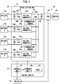
- a power supply system 10 includes a plurality of batteries 12a to 12d (power storage units), an equalization unit 14, a control device 16, a motor generator ECU (MG-ECU) 18, and a power drive unit (PDU) 20.
- FIG. 1 illustrates a case where four batteries 12a to 12d (hereinafter also referred to as the first to fourth batteries 12a to 12d) are arranged.
- the power supply system 10 at least two batteries may be disposed.
- the power supply system 10 is applied to a power supply system of an electric vehicle 22 such as a two wheeled vehicle or a four wheeled vehicle, for example.
- the plurality of batteries 12a to 12d are chargeable and dischargeable power storage units that can be attached to and detached from the power supply system 10.
- the plurality of batteries 12a to 12d are respectively housed in battery packs (not shown) including battery management systems (BMUs) for monitoring the batteries 12a to 12d, and can be attached to and detached from the power supply system 10 by attaching and detaching the battery packs to and from the power supply system 10.
- BMUs battery management systems
- at least one of the plurality of batteries 12a to 12d may be attached to and detached from the power supply system 10.
- each battery pack, the equalization unit 14, the control device 16, the MG-ECU 18, and the PDU 20 can transmit and receive signals or information via a communication line or the like (not illustrated) constituting a Controller Area Network (CAN).
- CAN Controller Area Network
- the equalization unit 14 includes a plurality of voltage converters 24a to 24d, a plurality of current measuring instruments 26a to 26d, a plurality of input-side voltage measuring instruments (voltage measuring instruments) 28a to 28d, an output-side voltage measuring instrument 30, and a plurality of temperature sensors 32.
- the plurality of voltage converters 24a to 24d are, for example, DC-DC converters each having an input side 34 that is a primary side and an output side 36 that is a secondary side.
- the voltage converters 24a to 24d convert voltages (battery voltages V1 to V4) of the batteries 12a to 12d connected to the input sides 34, at an arbitrary voltage conversion ratio Tr (step-up ratio Tru or step-down ratio Trd (hereinafter also referred to as step-down ratio R)), and output the converted voltages (output voltage V0) to the output sides 36.
- Tr step-up ratio Tru or step-down ratio Trd
- first to fourth voltage converters 24a to 24d illustrates a case where four voltage converters 24a to 24d (hereinafter also referred to as the first to fourth voltage converters 24a to 24d) are disposed in the equalization unit 14, correspondingly to the first to fourth batteries 12a to 12d, respectively.
- the first to fourth voltage converters 24a to 24d step down the battery voltages V1 to V4 of the first to fourth batteries 12a to 12d at arbitrary step-down ratios R1 to R4, and output the stepped down battery voltages V1 to V4 to the output sides 36 as the output voltage V0.
- the input side 34 of each of the first to fourth voltage converters 24a to 24d is connected to any one of the batteries 12a to 12d among the first to fourth batteries 12a to 12d. That is, the positive electrode terminals of the first to fourth batteries 12a to 12d are respectively connected to positive electrode terminals 38p on the input sides 34 of the first to fourth voltage converters 24a to 24d.
- the negative electrode terminals of the first to fourth batteries 12a to 12d are respectively connected to negative electrode terminals 38m on the input sides 34 of the first to fourth voltage converters 24a to 24d.
- the output sides 36 of the first to fourth voltage converters 24a to 24d are connected in parallel to each other and are thereby connected in parallel to the PDU 20.
- positive electrode terminals 40p on the output sides 36 of the first to fourth voltage converters 24a to 24d are connected to the positive electrode terminal of the PDU 20
- negative electrode terminals 40m on the output sides 36 of the first to fourth voltage converters 24a to 24d are connected to the negative electrode terminal of the PDU 20.
- the plurality of input side voltage measuring instruments 28a to 28d are voltage sensors respectively connected between the positive electrode terminals and the negative electrode terminals of the first to fourth batteries 12a to 12d on the input sides 34 of the first to fourth voltage converters 24a to 24d.
- the plurality of current measuring instruments 26a to 26d (hereinafter, also referred to as the first to fourth current measuring instruments 26a to 26d) are current sensors respectively connected between the positive electrode terminals of the first to fourth batteries 12a to 12d and the positive electrode terminals 38p of the first to fourth voltage converters 24a to 24d on the input sides 34 of the first to fourth voltage converters 24a to 24d.
- the output-side voltage measuring instrument 30 is a voltage sensor connected between the positive electrode terminal and the negative electrode terminal of the PDU 20 on the output sides 36 of the first to fourth voltage converters 24a to 24d.
- the plurality of temperature sensors 32 respectively detect the temperature of switching elements 42H and 42L (see FIGS. 2A to 2C ) that constitute each of the first to fourth voltage converters 24a to 24d.
- FIG. 1 shows a case where two temperature sensors 32 are provided.
- the PDU 20 is configured to include a three phase bridge inverter.
- the first to fourth voltage converters 24a to 24d are connected in parallel to the input side of the PDU 20.
- a three phase AC motor 44 which is a load of the power supply system 10, is electrically connected to the output side of the PDU 20.
- the PDU 20 converts the DC power into three phase AC power and supplies the AC power to the motor 44.
- the motor 44 can be driven, whereby the electric vehicle 22 can travel.
- the PDU 20 converts the AC power generated by the motor 44 into DC power.
- the first to fourth batteries 12a to 12d can be charged with DC power via the first to fourth voltage converters 24a to 24d.
- the MG-ECU 18 (power storage unit determination unit) is an ECU (electronic control unit) for controlling the PDU 20 and the motor 44, and can transmit and receive signals or information to and from the control device 16 and the PDU 20. That is, the MG-ECU 18 supplies control signals (signals indicating command values of torque) for operating the switching elements 42H and 42L constituting the PDU 20.
- the PDU 20 transmits the state or the like of the PDU 20.
- the motor 44 transmits the state or the like of the motor 44.
- the MG-ECU 18 calculates a required output of the motor 44 based on the information or the like transmitted from the PDU 20 and the motor 44, and transmits the calculated required output to the control device 16.
- the control device 16 is an ECU for controlling the equalization unit 14, and includes a control unit 46 (power storage unit determination unit, current difference determination unit, voltage conversion ratio determination unit), a command unit 48, and a table 50.
- the control unit 46 acquires: the battery voltages V1 to V4 of the first to fourth batteries 12a to 12d measured by the first to fourth voltage measuring instruments 28a to 28d; first to fourth currents I1 to I4 measured by the first to fourth current measuring instruments 26a to 26d; the output voltage V0 (load voltage) measured by the output-side voltage measuring instrument 30; and the temperatures of the first to fourth voltage converters 24a to 24d measured by the plurality of temperature sensors 32.
- control unit 46 calculates (determines) the voltage conversion ratio Tr and the like, based on the required output from the MG-ECU 18 and the target value of the current (target current Itar) flowing through the input side 34.
- the target current Itar is stored in the table 50.
- the command unit 48 outputs, to the equalization unit 14, command signals (gate signals supplied to the switching elements 42H and 42L of the first to fourth voltage converters 24a to 24d) that are based on the voltage conversion ratio Tr determined by the control unit 46.
- the details of the processes of the control device 16 and the MG-ECU 18 will be described later.
- FIGS. 2A to 2C are circuit diagrams showing specific examples of the first to fourth voltage converters 24a to 24d in FIG. 1 .
- the first to fourth voltage converters 24a to 24d are, for example, step-down or step-up/step-down DC-DC converters (see FIG. 2A ), step-down DC-DC converters (see FIG. 2B ), or step-up/step-down DC-DC converters (see FIG. 2C ).
- the configuration and operation of these DC-DC converters are well known. Therefore, here, a connection relationship of respective components in the circuit diagrams of FIGS. 2A to 2C will be briefly described.
- a capacitor 52 is connected between the positive electrode terminal 38p and the negative electrode terminal 38m on the input side 34.
- Two sets of circuits each of which is formed of a set of two switching elements 42H and 42L connected in series and a coil 54, are connected in parallel to the capacitor 52.
- the switching element 42H is a high-side switching element connected to the positive electrode terminal 38p of the capacitor 52.
- the switching element 42L is a low-side switching element connected to the negative electrode terminal 38m of the capacitor 52 and the negative electrode terminal 40m on the output side 36.
- One end of the coil 54 is connected to a midpoint between the two switching elements 42H and 42L. The other end of the coil 54 is connected to the positive electrode terminal 40p on the output side 36.
- a capacitor 56 is connected between the positive electrode terminal 40p and the negative electrode terminal 40m on the output side 36.
- Each of the switching elements 42H and 42L is formed by connecting in parallel a MOSFET (Metal Oxide Semiconductor Field Effect Transistor) 58 and a Zener diode 60 that is a parasitic diode.
- MOSFET Metal Oxide Semiconductor Field Effect Transistor
- the capacitor 52 is connected between the positive electrode terminal 38p and the negative electrode terminal 38m on the input side 34.
- Two switching elements 42H and 42L connected in series are connected in parallel to the capacitor 52.
- the switching element 42H is a high-side switching element connected to the positive electrode terminal 38p of the capacitor 52.
- the switching element 42L is a low-side switching element connected to the negative electrode terminal 38m of the capacitor 52 and the negative electrode terminal 40m on the output side 36.
- a series circuit of the coil 54 and a resistor 62 is connected between the midpoint of the two switching elements 42H and 42L and the positive electrode terminal 40p on the output side 36.
- the capacitor 56 is connected between the positive electrode terminal 40p and the negative electrode terminal 40m on the output side 36.
- the capacitor 52 is connected between the positive electrode terminal 38p and the negative electrode terminal 38m on the input side 34.
- the positive electrode terminal 38p of the capacitor 52 is connected, via a series circuit of a coil 64 and a resistor 66, to the midpoint between the two switching elements 42H and 42L connected in series.
- a capacitor 68 is connected in parallel to the two switching elements 42H and 42L. Further, a circuit having the same configuration as that in FIG. 2B is connected in parallel to the output side 36 of the capacitor 68.
- each circuit configuration by changing the duty of the gate signal supplied to the gate terminal of each switching element 42H, 42L (MOSFET 58), it is possible to change the voltage conversion ratio Tr (the step-up ratio Tru or the step-down ratio R in FIG. 2A , the step-down ratio R in FIG. 2B , and the step-up ratio Tru or the step-down ratio R in FIG. 2C ).
- FIG. 3 shows, as an example, a timing chart of gate signals supplied to the gate terminals of the switching elements 42H and 42L in the step-down circuit of FIG. 2B .
- T a period of the gate signal
- U a high-level time of the gate signal supplied to the high-side switching element 42H
- D a high-level time of the gate signal supplied to the low-side switching element 42L
- Td a dead time, which is a time interval between the time U and the time D
- a desired output voltage V0 can be obtained.
- characteristic functions of the power supply system 10 and the control method thereof according to the present embodiment (hereinafter also referred to as characteristic functions of the present embodiment) will be described with reference to FIGS. 4 to 17 .
- the characteristic functions of the present embodiment are as follows: when the first to fourth batteries 12a to 12d having different voltages or SOCs are connected in parallel to each other and charging and discharging are performed by causing the first to fourth currents I1 to I4 to flow among the first to fourth batteries 12a to 12d so that the voltages or the SOCs are equal to each other, the first to fourth currents I1 to I4 flowing from the first to fourth batteries 12a to 12d to the input sides 34 are fed back to the control device 16, the control unit 46 of the control device 16 determines the current difference between the current flowing from the battery to be charged (reference power storage unit) and the current flowing from the battery to be discharged (remaining power storage unit), then determines the step-down ratio R such that the determined current difference becomes small, and controls the first to fourth voltage converters 24a to
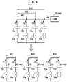
- FIG. 4 is a schematic circuit diagram of the power supply system 10 shown in FIG. 1 .
- the equalization unit 14 and the like are not shown.
- Series circuits of the first to fourth batteries 12a to 12d and resistors 70a to 70d (hereinafter, also referred to as the first to fourth resistors 70a to 70d) indicating internal resistances (resistance values r) of the first to fourth batteries 12a to 12d are connected in parallel.
- a load 72 (motor 44) is connected to the positive electrodes of the first to fourth batteries 12a to 12d.
- the current flowing through the load 72 is represented by It (hereinafter also referred to as load current).
- load current a voltage difference between the positive electrode side of the series circuit of the first battery 12a and the first resister 70a, and the positive electrode side of the series circuit of the second battery 12b and the second resister 70b is represented by Vd1.
- a voltage difference between the positive electrode side of the series circuit of the first battery 12a and the first resister 70a, and the positive electrode side of the series circuit of the third battery 12c and the third resister 70c is represented by Vd2.
- a voltage difference between the positive electrode side of the series circuit of the first battery 12a and the first resister 70a, and the positive electrode side of the series circuit of the fourth battery 12d and the fourth resister 70d is represented by Vd3.
- the first current I1 and the second current I2 are expressed by the following expressions (5) and (6) based on Kirchhoff's law.
- I 1 It / 2 + Vd 1 / 4 ⁇ r
- I 2 It / 2 ⁇ Vd 1 / 4 ⁇ r
- the first to third currents I1 to I3 are expressed by the following expressions (7) to (9) based on Kirchhoff's law.
- I 1 It / 3 + Vd 1 + Vd 2 / 6 ⁇ r
- I 2 It / 3 + ⁇ 2 ⁇ Vd 1 + Vd 2 / 6 ⁇ r
- I 3 It / 3 + Vd 1 ⁇ 2 ⁇ Vd 2 / 6 ⁇ r
- the first to fourth currents I1 to I4 are expressed by the following expressions (10) to (13) based on Kirchhoff's law.
- I 1 It / 4 + Vd 1 + Vd 2 + Vd 3 / 8 ⁇ r
- I 2 It / 4 + ⁇ 3 ⁇ Vd 1 + Vd 2 + Vd 3 / 8 ⁇ r
- I 3 It / 4 + Vd 1 ⁇ 3 ⁇ Vd 2 + Vd 3 / 8 ⁇ r
- I 4 It / 4 + Vd 1 + Vd 2 ⁇ 3 ⁇ Vd 3 / 8 ⁇ r
- the first to fourth currents I1 to I4 include the voltage differences Vd1 to Vd3. Therefore, theoretically, if the first to fourth currents I1 to I4 are measured by the first to fourth current measuring instruments 26a to 26d and the measured first to fourth currents I1 to I4 are fed back to the control device 16, it is possible to adjust the voltage differences Vd1 to Vd3 to desired voltage differences based on the first to fourth currents I1 to 14.
- FIGS. 5A and 5B are timing charts showing examples of temporal changes of the first current I1, the second current 12, and the load current It.
- FIG. 5A shows a case where feedback of the first current I1 and the second current I2 is not performed.
- FIG. 5B shows a case where feedback of the first current I1 and the second current I2 is performed.
- a current difference of 2 ⁇ A is generated between the first current I1 and the second current I2 due to the voltage difference Vd1.
- the first current I1 is a negative current, that is, a charging current.
- the second current I2 is a positive current, that is, a discharge current. That is, since the load 72 is not present, the second current I2 flowing from the second battery 12b flows into the first battery 12a as the first current I1. Thus, the first battery 12a is charged.
- the time period from the time point t1 to a time point t2 is the power running period in which the load 72 is present.
- a current difference of 2 ⁇ B is generated between the first current I1 and the second current I2 due to the voltage difference Vd1.
- both the first current I1 and the second current I2 are discharge currents. That is, the first current I1 and the second current I2 flowing from the first battery 12a and the second battery 12b flow to the load 72 as the load current It.
- the time period from the time point t2 to a time point t3 is the regenerative period in which the load 72 is present, and the first battery 12a and the second battery 12b are charged from the load 72.
- a current difference of 2 ⁇ C is generated between the first current I1 and the second current I2 due to the voltage difference Vd1.
- both the first current I1 and the second current I2 are charging currents. That is, the load current It is divided into the first current I1 and the second current 12.
- the divided first current I1 flows into the first battery 12a, and the divided second current I2 flows into the second battery 12b.
- the first current I1 and the second current I2 are fed back to the control device 16, and the voltage difference Vd1 is controlled so that the current difference between the first current I1 and the second current I2 that have been fed back becomes small.
- the current difference changes so as to gradually decrease to 0. That is, the first current I1 and the second current I2 change so as to have the same current value as the load current It.
- a certain current difference occurs in the time period from t0 to t1 and the time period after t3 in which the load 72 is not present.
- FIG. 6 is an explanatory diagram illustrating a method of charging and discharging the first to fourth batteries 12a to 12d (see FIGS. 1 and 4 ) in the present embodiment.
- MPP1 to MPP4 indicate the first to fourth batteries 12a to 12d.
- a symbol such as “3H1L” indicates the number (the number indicated before “H") of batteries (remaining power storage units) to be discharged, and the number (the number indicated before “L”) of batteries (reference power storage units) to be charged.
- target values (target currents Itar) of the first to fourth currents I1 to I4 are indicated below the graphic symbols (figures of batteries) indicating the first to fourth batteries 12a to 12d.
- the target current Itar of the battery to be discharged is indicated by a symbol such as "Id”.
- the target current Itar indicates a target value of the current flowing from the battery to be discharged.
- the target current of the battery to be discharged is set to 0 [A]. Therefore, the actual current value (actual current) flowing from each of the first to fourth batteries 12a to 12d may be different from the target current.
- the target currents of the first to fourth currents I1 to I4 are set to 3.0 ⁇ Id [A], 0.0 [A], 0.0 [A], and 0.0 [A].
- actual currents of the first to fourth currents I1 to I4 are + 2.25 ⁇ Id [A], - 0.75 ⁇ Id [A], - 0.75 ⁇ Id [A], and - 0.75 ⁇ Id [A].
- the positive and negative signs given to the first to fourth currents I1 to I4 are such that the direction in which the current flows from the first to fourth batteries 12a to 12d to the first to fourth voltage converters 24a to 24d is a positive (+) direction, and the direction in which the current flows from the first to fourth voltage converters 24a to 24d to the first to fourth batteries 12a to 12d is a negative (-) direction.
- the target current Itar is set in advance in the table 50 (see FIG. 1 ).
- the control unit 46 changes each target current Itar in accordance with the number of batteries to be charged (reference power storage units), the number of batteries to be discharged (remaining power storage units), the sum of currents flowing from the plurality of batteries 12a to 12d, and the like described later.
- the number of batteries to be charged and the number of batteries to be discharged are sequentially changed from the upper side to the lower side of the list of FIG. 6 . More specifically, the first to fourth batteries 12a to 12d are charged and discharged by sequentially reducing the number of batteries to be discharged.
- R 0.94
- a current is caused to flow from the battery to be discharged to the battery to be charged while maintaining a voltage difference between the battery to be charged and the battery to be discharged.
- the battery to be charged is charged.
- the step-down ratio R of the voltage converter connected to the battery to be discharged is set to be relatively lower than the step-down ratio R of the voltage converter connected to the battery to be charged.
- the maximum step-down ratio is a maximum step-down ratio that can be set in consideration of the dead time Td.
- FIG. 7 is a sequence diagram of charge/discharge control for the first to fourth batteries 12a to 12d when the power supply system 10 according to the present embodiment is applied to the electric vehicle 22, to be more specific, when the motor 44 is used as a drive source for wheels of the electric vehicle 22.
- FIG. 8 is a flowchart showing operations of the equalization unit 14 and the control device 16 in the charge/discharge control of FIG. 7 .
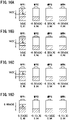
- charge/discharge control will be described in a case where the battery voltage V1 of the first battery 12a is the lowest and the battery voltages V1 to V4 of the first to fourth batteries 12a to 12d become higher in this order as illustrated in FIGS. 9A and 9B .
- step S1 the overall flow of charge/discharge control will be described with reference to FIG. 7 .
- IG ignition switch
- step S2 each BMU is activated based on the activation command from the MG-ECU 18.
- the MG-ECU 18 also performs a numbering process on each BMU.
- the numbering process four batteries 12a to 12d are set as the first to fourth batteries 12a to 12d. Accordingly, each of the four batteries 12a to 12d is allocated to any of the first to fourth batteries 12a to 12d.
- the MG-ECU 18 notifies the control unit 46 of the control device 16 of the result of the numbering process.
- the capacitors 52, 56, and 68 are present in the first to fourth voltage converters 24a to 24d (see FIGS. 2A to 2C ). Therefore, as shown in FIG. 10 , even if the electric vehicle 22 stops and the ignition switch is turned off at a time point t4, a constant voltage is generated by the charges accumulated in the capacitors 52, 56, and 68, more specifically, by the charges stored between the equalization unit 14 and the PDU 20. Therefore, for example, in the time period from a time point t5 when the ignition switch is turned on to a time point t6, the control unit 46 of the control device 16 instructs the command unit 48 to execute a discharging process in step S3.
- step S4 the command unit 48 supplies a gate signal to the equalization unit 14 based on an instruction from the control unit 46. Accordingly, the switching elements 42H and 42L are turned on. As a result, the charges of the capacitors 52, 56, and 68 are discharged in the time period from the time point t5 to the time point t6, and the output voltage V0 can be decreased to near 0 [V].
- the discharging process of steps S3 and S4 is executed after step S2.
- the discharging process may be executed after the ignition switch is turned on (time point t5 in FIG. 10 ) and before a process of step S9 described later is performed (time point t7).
- step S5 voltage sensors (not shown) in the battery packs detect the voltages (battery voltages V1 to V4) of the first to fourth batteries 12a to 12d. Accordingly, in step S6, the equalization unit 14 can grasp the battery voltages V1 to V4.
- FIG. 9A the battery voltages detected by the voltage sensors are shown as Vlcan to V4can. Further, the detection results from the voltage sensors are transmitted from the respective battery packs to the control device 16. The control device 16 transfers the detection results to the MG-ECU 18.
- step S8 the control unit 46 of the control device 16 executes a control process for charge/discharge control based on the instruction from the MG-ECU 18, and instructs the command unit 48 to output gate signals. Accordingly, the command unit 48 starts supply of the gate signals to the equalization unit 14 based on the instruction from the control unit 46. As a result, in step S9, the switching elements 42H and 42L are driven in the equalization unit 14 based on the supplied gate signals. Thus, the charge/discharge control (equalization control) is started from the time point t7. That is, in the time period from t5 to t7 in FIG. 10 , the processes from step S1 to step S8 in FIG. 7 as the initial process for the charge/discharge control are executed.
- step S10 the MG-ECU 18 instructs each battery pack to execute a precharge process for charging a capacitor (not shown) in the battery pack.
- step S11 the capacitor is charged in each battery pack based on the instruction from the MG-ECU 18.
- steps S10 and S11 the capacitors 52, 56, and 68 of the voltage converters 24a to 24d may also be charged. Further, in the present embodiment, the processes of steps S10 and S11 may be included in the initial process.
- step S12 the MG-ECU 18 instructs each battery pack to turn on a switching element (not shown) in the battery pack.
- each battery pack turns on the switching element at a time point t8 in FIG. 10 based on the instruction from the MG-ECU 18.
- the first to fourth batteries 12a to 12d are electrically connected to the first to fourth voltage converters 24a to 24d.
- the time point t8 it is possible to cause the current to flow from the first to fourth batteries 12a to 12d to the first to fourth voltage converters 24a to 24d, and charging and discharging of the first to fourth batteries 12a to 12d are performed.
- step S15 the charge/discharge control (equalization control) is also stopped.
- steps S1, S7, S11, and S13 may be performed by the control device 16.
- FIG. 8 is a flowchart showing a specific method of the equalization control in FIG. 7 . That is, the flowchart of FIG. 8 illustrates the flow of operations of the control device 16 and the equalization unit 14 in the time period from step S9 to step S15.
- step S21 the MG-ECU 18 or the control unit 46 determines a battery having the lowest battery voltage among the first to fourth batteries 12a to 12d, as a battery to be charged (reference power storage unit). As illustrated in FIG. 9A , the battery voltage V1 (V1can) of the first battery 12a is the lowest. Therefore, the control unit 46 determines the first battery 12a as the battery to be charged. From step S9 to step S12 in FIG. 7 , the switching element of each battery pack is off. Therefore, the first to fourth batteries 12a to 12d are not electrically connected to the first to fourth voltage converters 24a to 24d.
- the MG-ECU 18 or the control unit 46 may determine the first battery 12a as the battery to be charged based on the battery voltages V1 to V4 (V1can to V4can) of the first to fourth batteries 12a to 12d, as detected by voltage sensors (not shown) in the respective battery packs.
- the control unit 46 sets a reference voltage Vref that is based on the battery voltage V1 of the first battery 12a.
- the reference voltage Vref is calculated by the following expression (14) using the battery voltage V1 of the first battery 12a and a step-down ratio R1 of the first voltage converter 24a connected to the first battery 12a.
- Vref R 1 ⁇ lowest battery voltage V 1
- the control unit 46 sets the values (initial values) of the battery voltages V1 to V4 of the first to fourth batteries 12a to 12d used in the charging and discharging process, to the reference voltage Vref, whereby the values of the battery voltages V1 to V4 are equalized.
- the voltage differences among the first to fourth batteries 12a to 12d temporarily become 0 [V].
- the first to fourth batteries 12a to 12d are electrically connected to the first to fourth voltage converters 24a to 24d, whereby the first to fourth voltage measuring instruments 28a to 28d can measure the battery voltages V1 to V4 of the first to fourth batteries 12a to 12d, and the first to fourth current measuring instruments 26a to 26d can measure the first to fourth currents I1 to 14.
- the control unit 46 acquires the battery voltages V1 to V4 of the first to fourth batteries 12a to 12d from the first to fourth voltage measuring instruments 28a to 28d, and acquires the first to fourth currents I1 to I4 from the first to fourth current measuring instruments 26a to 26d.
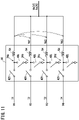
- FIG. 11 is a block diagram schematically illustrating the equalization unit 14.
- FIG. 12 is a block diagram illustrating the charge/discharge control in the control device 16 and the equalization unit 14.
- the "control target" is the power supply system 10 including the equalization unit 14.
- "s" in the "kp + kds” block and the "1/s" block is a variable of a complex number in the Laplace transform.
- the control unit 46 sets the first battery 12a as the battery to be charged (reference power storage unit), and sets the second to fourth batteries 12b to 12d as the batteries to be discharged (remaining power storage units). Therefore, the control unit 46 subtracts each of the second to fourth currents I2 to I4 from the first current I1.
- next step S24 based on the acquired battery voltages V1 to V4, the control unit 46 determines to which state in FIG. 6 the charge/discharge state at the present time corresponds. In this case, the control unit 46 determines that the state is "3H1L" in FIG. 6 .
- the control unit 46 adds target currents Itar2 to Itar4 to the current differences obtained by subtraction in step S23.
- the current difference between the first current I1 and each of the second to fourth currents I2 to I4 is calculated.
- Current differences ⁇ I2 to ⁇ I4 in expressions (15) to (17) are target currents (target operation currents) for actually controlling the first to fourth voltage converters 24a to 24d. That is, the control unit 46 can set the target operation currents ⁇ I2 to ⁇ I4 by adding the target currents Itar2 to Itar4 to the respective current differences.
- next step S25 as in the following expressions (18) to (20), the control unit 46 uses the target operation currents (current differences) ⁇ I2 to ⁇ I4 calculated in step S24 to calculate voltage differences Vd1 to Vd3 between the battery voltage V1 of the first battery 12a and the battery voltages V2 to V4 of the second to fourth batteries 12b to 12d.
- " ⁇ " is an integral symbol.
- kp and kd are fixed coefficients in feedback control.
- ⁇ I2p to ⁇ I4p are previous target operation currents.
- Vd 1 ⁇ kp ⁇ ⁇ I 2 + kd ⁇ ⁇ I 2 ⁇ ⁇ I2p
- Vd 2 ⁇ kp ⁇ ⁇ I 3 + kd ⁇ ⁇ I 3 ⁇ ⁇ I 3 p
- Vd 3 ⁇ kp ⁇ ⁇ I 4 + kd ⁇ ⁇ I 4 ⁇ ⁇ I 4 p
- step S26 the control unit 46 calculates the step-down ratios R2 to R4 using the calculated voltage differences Vd1 to Vd3.
- step S27 the command unit 48 outputs gate signals based on the step-down ratios R1 to R4, to the equalization unit 14.
- the switching elements 42H and 42L of the first to fourth voltage converters 24a to 24d are driven based on the supplied gate signals.
- step S28 the current values of the first to fourth currents I1 to I4 are changed by the voltage differences Vd1 to Vd3 shown in FIG. 9B .
- step S29 the control unit 46 determines whether to stop the equalization control. If step S15 has not been reached, the control unit 46 determines to continue the equalization control (step S29: NO), returns to step S22, and performs the processes of steps S22 to S29 again. Therefore, every time the processes of steps S22 to S29 are repeatedly executed, the states of the first to fourth batteries 12a to 12d are sequentially switched from "3H1L” to "2H2L", “1H3L", and "0H4L” in FIG. 6 . Thereafter, when step S15 is reached, the control unit 46 stops the equalization control (step S29: YES).
- FIG. 13 is a timing chart showing the effect of the control process of FIG. 8 .
- the target current Itar is set.
- the switching elements 42H and 42L are driven by the voltage difference Vd1 based on the target current Itar, whereby the second current I2 rapidly increases toward the target current Itar with the lapse of time after the time point t9.
- the difference between the target current Itar and the second current I2 at an arbitrary time point t10 is the target operation current (current difference) ⁇ I2.
- an area of a portion surrounded by the target current Itar and the second current I2 indicates the voltage difference Vd1.
- FIG. 14 is a timing chart showing temporal changes of the first to fourth currents I1 to 14, the battery voltages V1 to V4, and the step-down ratios R1 to R4 in the charge/discharge control according to the present embodiment.
- N 4 and the batteries to be discharged and the batteries to be charged are switched in the order of "3H1L” -> "2H2L” -> "1H3L” -> "0H4L” at time points t11, t12, t13, and t14.
- the battery to be charged is the fourth battery 12d
- the step-down ratio R4 of the fourth voltage converter 24d connected to the fourth battery 12d is fixed to 0.91. Therefore, initially, the first to third batteries 12a to 12c serve as the batteries to be discharged.
- the first to third currents I1 to I3 are discharge currents (positive currents), and the fourth current I4 is a charging current (negative current).
- the step-down ratios R1 to R3 of the first to third voltage converters 24a to 24c increase over time.
- the step-down ratios R2 and R3 of the second and third voltage converters 24b and 24c reach near 0.96 (the upper limit value of the settable step-down ratio)
- "3H1L" is switched to "2H2L".
- the step-down ratios R1 and R3 of the first and third voltage converters 24a and 24c increase over time.
- the step-down ratio R2 of the second voltage converter 24b decreases to the step-down ratio R4 (0.91) of the fourth voltage converter 24d.
- the step-down ratio R3 of the third voltage converter 24c reaches near 0.96 at the time point t13, "2H2L" is switched to "1H3L".
- the step-down ratio R1 of the first voltage converter 24a increases over time.
- the step-down ratio R3 of the third voltage converter 24c decreases to the step-down ratios R2 and R4 (0.91) of the second and fourth voltage converters 24b and 24d.
- the step-down ratio R (R1 to R4) for such charge/discharge control is as follows.
- the battery voltages V1 to V4 of the first to fourth batteries 12a to 12d in a fully charged state are defined as Vi [V].
- a portion of each of the step-down ratios R1 to R4 corresponding to the dead time Td is set to 0.31.
- the current is caused to flow from the battery to be discharged to the battery to be charged.
- the battery to be charged is charged.
- the initial step-down ratio R1 of the first voltage converter 24a is set to 0.81
- the step-down ratios R2 to R4 of the second to fourth voltage converters 24b to 24d are set (fixed) to 0.94.
- the voltage difference between the first battery 12a and each of the second to fourth batteries 12b to 12d is set to Vd [V].
- FIG. 17 is a timing chart showing temporal changes of the vehicle speed, the current, and the SOC when the power supply system 10 according to the present embodiment is mounted on the electric vehicle 22.
- the electric vehicle 22 activated in the time period before a time point t15 stops in the time period from the time point t15 to a time point t16, and thereafter, performs acceleration traveling from the time point t16. Thereafter, the electric vehicle 22 performs cruising from a time point t17, changes to deceleration traveling from a time point t18, and stops at a time point t19.
- the present embodiment relates to the power supply system 10 and the control method thereof, the power supply system 10 including: a plurality of chargeable and dischargeable batteries 12a to 12d (power storage units); a plurality of voltage converters 24a to 24d having input sides 34 connected to the plurality of batteries 12a to 12d, respectively, and output sides 36 connected in parallel to each other, the voltage converters 24a to 24d being configured to convert the voltages V1 to V4 of the plurality of batteries 12a to 12d connected to the input sides 34 at arbitrary voltage conversion ratios Tr and output the converted voltages V0 to the output sides 36; and a plurality of current measuring instruments 26a to 26d connected to the input sides 34 of the plurality of voltage converters 24a to 24d, respectively, and configured to measure the currents I1 to I4 flowing from the plurality of batteries 12a to 12d to the input sides 34.
- a plurality of chargeable and dischargeable batteries 12a to 12d power storage units
- a plurality of voltage converters 24a to 24d having input sides 34
- the power supply system 10 includes: a power storage unit determination unit (the MG-ECU 18, the control unit 46) configured to determine at least one of the plurality of batteries 12a to 12d as a battery to be charged (reference power storage unit) and determine the remaining batteries as batteries to be discharged (remaining power storage units); a current difference determination unit (the control unit 46) configured to determine a current difference between each of the currents flowing from the batteries to be discharged and the current flowing from the battery to be charged, based on the currents I1 to I4 measured by the plurality of current measuring instruments 26a to 26d; and a voltage conversion ratio determination unit (the control unit 46) configured to determine the voltage conversion ratio Tr of each of the voltage converters connected to the batteries to be discharged, based on the determined current difference.
- a power storage unit determination unit the MG-ECU 18, the control unit 46
- the control unit 46 configured to determine at least one of the plurality of batteries 12a to 12d as a battery to be charged (reference power storage unit) and determine the remaining
- the method for controlling the power supply system 10 includes: the step (step S7) of using the MG-ECU 18 or the control unit 46 to determine at least one of the plurality of batteries 12a to 12d as a battery to be charged and determine the remaining batteries as batteries to be discharged; the step (steps S23 and S24) of using the control unit 46 to determine a current difference between each of the currents flowing from the batteries to be discharged and the current flowing from the battery to be charged, based on the currents I1 to I4 measured by the plurality of current measuring instruments 26a to 26d; and the step (step S26) of using the control unit 46 to determine the voltage conversion ratio Tr of each of the voltage converters connected to the batteries to be discharged, based on the determined current difference.
- the current difference between each of the currents flowing from the batteries to be discharged and the current flowing from the battery to be charged is fed back, and the voltage conversion ratio Tr of each of the voltage converters connected to the batteries to be discharged is determined so that the current difference becomes small.
- the plurality of batteries 12a to 12d are connected in parallel to each other via the voltage converters 24a to 24d, it is possible to equalize the battery voltages V1 to V4 or the SOCs of the plurality of batteries 12a to 12d connected in parallel to each other while avoiding deterioration of the batteries 12a to 12d.
- the MG-ECU 18 or the control unit 46 determines, as the battery to be charged, the battery having the lowest voltage among the plurality of batteries 12a to 12d, and determines the remaining batteries as the batteries to be discharged. This makes it possible to efficiently determine the batteries to be discharged and the battery to be charged.
- the control unit 46 calculates the current difference by subtracting each of the currents flowing from the batteries to be discharged from the current flowing from the battery to be charged, and adding together the current obtained by the subtraction and the target current Itar. By such feedback control, it is possible to perform charge/discharge control while preventing the current flowing from each of the batteries 12a to 12d from becoming excessive.
- the current value of the target current Itar is set in accordance with the number of the plurality of batteries 12a to 12d, the number of the batteries to be charged, or the sum of the currents flowing from the plurality of batteries 12a to 12d.
- the target current can be appropriately set in accordance with the number of the batteries 12a to 12d.
- control unit 46 calculates the voltage difference between the battery voltage of the battery to be charged and each of the battery voltages of the batteries to be discharged, based on the current difference, and determines the voltage conversion ratio Tr of each of the voltage converters connected to the batteries to be discharged by using the calculated voltage difference. In this way, the voltage conversion ratio Tr is determined using the voltage difference reflecting the current difference. Accordingly, it is possible to prevent the current flowing from each of the batteries 12a to 12d from becoming excessive, and to efficiently suppress the occurrence of deterioration of the batteries 12a to 12d.
- the present invention is not limited to the above-described embodiment, and it goes without saying that various configurations could be adopted therein based on the contents described in this specification.
Landscapes
- Engineering & Computer Science (AREA)
- Power Engineering (AREA)
- Physics & Mathematics (AREA)
- General Physics & Mathematics (AREA)
- Charge And Discharge Circuits For Batteries Or The Like (AREA)
- Secondary Cells (AREA)
Applications Claiming Priority (2)
| Application Number | Priority Date | Filing Date | Title |
|---|---|---|---|
| JP2019209519 | 2019-11-20 | ||
| PCT/JP2020/043159 WO2021100799A1 (fr) | 2019-11-20 | 2020-11-19 | Système d'alimentation électrique et son procédé de commande |
Publications (3)
| Publication Number | Publication Date |
|---|---|
| EP4064517A1 true EP4064517A1 (fr) | 2022-09-28 |
| EP4064517A4 EP4064517A4 (fr) | 2023-04-12 |
| EP4064517B1 EP4064517B1 (fr) | 2024-07-03 |
Family
ID=75980117
Family Applications (1)
| Application Number | Title | Priority Date | Filing Date |
|---|---|---|---|
| EP20889216.6A Active EP4064517B1 (fr) | 2019-11-20 | 2020-11-19 | Système d'alimentation électrique et son procédé de commande |
Country Status (5)
| Country | Link |
|---|---|
| US (1) | US11646599B2 (fr) |
| EP (1) | EP4064517B1 (fr) |
| JP (1) | JP7147080B2 (fr) |
| CN (1) | CN114731055B (fr) |
| WO (1) | WO2021100799A1 (fr) |
Families Citing this family (5)
| Publication number | Priority date | Publication date | Assignee | Title |
|---|---|---|---|---|
| US12555991B2 (en) * | 2017-06-26 | 2026-02-17 | Swidget Corporation | Configurable electrical receptacles |
| US12463438B2 (en) * | 2020-12-23 | 2025-11-04 | Samsung Electronics Co., Ltd. | Wearable electronic device including multiple batteries and method for operating the same |
| KR102882635B1 (ko) * | 2021-01-13 | 2025-11-05 | 주식회사 엘지에너지솔루션 | 배터리 뱅크 전력 제어 장치 및 방법 |
| CN113765177B (zh) * | 2021-07-30 | 2024-06-11 | 华为数字能源技术有限公司 | 一种电池模块和充电系统 |
| JP7522706B2 (ja) * | 2021-08-18 | 2024-07-25 | 矢崎総業株式会社 | 電源制御装置、電源装置、及び電源制御方法 |
Family Cites Families (15)
| Publication number | Priority date | Publication date | Assignee | Title |
|---|---|---|---|---|
| US3667025A (en) * | 1971-06-21 | 1972-05-30 | Gen Motors Corp | Dual voltage system |
| JP4984754B2 (ja) * | 2006-09-04 | 2012-07-25 | トヨタ自動車株式会社 | 電源システムおよびそれを備えた車両 |
| JP4840197B2 (ja) * | 2007-03-06 | 2011-12-21 | トヨタ自動車株式会社 | 車両の電源装置および車両の電源装置の制御方法 |
| JP4450004B2 (ja) * | 2007-03-30 | 2010-04-14 | トヨタ自動車株式会社 | 電源回路の制御装置および制御方法 |
| JP5359214B2 (ja) * | 2008-11-19 | 2013-12-04 | 株式会社明電舎 | 直流電源のチョッパ制御方法および前記直流電源のチョッパ制御方法を用いた移動車両 |
| US8598734B2 (en) | 2009-05-08 | 2013-12-03 | Toyota Jidosha Kabushiki Kaisha | Power supply system and vehicle equipped with the same |
| CN103635822B (zh) * | 2011-08-30 | 2016-02-10 | 三洋电机株式会社 | 电池系统、电动车辆、移动体、电力储存装置以及电源装置 |
| JP5680769B2 (ja) * | 2012-07-13 | 2015-03-04 | パナソニックIpマネジメント株式会社 | 蓄電池システム及びその制御方法 |
| JP6133817B2 (ja) * | 2014-05-14 | 2017-05-24 | 本田技研工業株式会社 | 2電源システム及び電動車両 |
| JP6293010B2 (ja) | 2014-07-23 | 2018-03-14 | 本田技研工業株式会社 | 蓄電システム |
| JP6442949B2 (ja) * | 2014-09-22 | 2018-12-26 | 住友電気工業株式会社 | 蓄電システム |
| JP6518603B2 (ja) * | 2016-02-24 | 2019-05-22 | 本田技研工業株式会社 | 電源装置、機器及び制御方法 |
| JP6652427B2 (ja) * | 2016-03-29 | 2020-02-26 | 本田技研工業株式会社 | 電力供給システム及び輸送機器 |
| JP6652428B2 (ja) * | 2016-03-29 | 2020-02-26 | 本田技研工業株式会社 | 電力供給システム及び輸送機器、並びに、電力供給システムの制御方法 |
| JP6993286B2 (ja) * | 2018-04-26 | 2022-01-13 | 京セラ株式会社 | 蓄電装置、蓄電装置の制御装置及び蓄電装置の制御方法 |
-
2020
- 2020-11-19 US US17/778,029 patent/US11646599B2/en active Active
- 2020-11-19 WO PCT/JP2020/043159 patent/WO2021100799A1/fr not_active Ceased
- 2020-11-19 EP EP20889216.6A patent/EP4064517B1/fr active Active
- 2020-11-19 JP JP2021558438A patent/JP7147080B2/ja active Active
- 2020-11-19 CN CN202080080813.XA patent/CN114731055B/zh active Active
Also Published As
| Publication number | Publication date |
|---|---|
| EP4064517B1 (fr) | 2024-07-03 |
| CN114731055B (zh) | 2025-08-29 |
| EP4064517A4 (fr) | 2023-04-12 |
| CN114731055A (zh) | 2022-07-08 |
| JPWO2021100799A1 (fr) | 2021-05-27 |
| US11646599B2 (en) | 2023-05-09 |
| JP7147080B2 (ja) | 2022-10-04 |
| US20220416562A1 (en) | 2022-12-29 |
| WO2021100799A1 (fr) | 2021-05-27 |
Similar Documents
| Publication | Publication Date | Title |
|---|---|---|
| EP4064517B1 (fr) | Système d'alimentation électrique et son procédé de commande | |
| US11594895B2 (en) | Power supply system | |
| EP3588733B1 (fr) | Dispositif d'alimentation électrique | |
| JP4380772B2 (ja) | 電源装置およびそれを備えた車両、電源装置の制御方法、ならびにその制御方法をコンピュータに実行させるためのプログラムを記録したコンピュータ読取可能な記録媒体 | |
| JP4984754B2 (ja) | 電源システムおよびそれを備えた車両 | |
| JP5374210B2 (ja) | Dc/dcコンバータおよびそれを用いた給電システム | |
| JP2020519223A (ja) | 分散型バッテリ、バッテリ制御方法、及び電気自動車 | |
| EP2983270A1 (fr) | Dispositif de commande, dispositif de commande d'alimentation électrique, procédé de commande de charge, dispositif de commande de charge et dispositif d'alimentation électrique pour un véhicule | |
| JP2020043718A (ja) | 電動車両 | |
| JP6427574B2 (ja) | パワーバッテリーの素子の充電平衡化装置 | |
| US8760111B2 (en) | Secondary battery output power controller | |
| US9755439B2 (en) | Battery state control circuit, battery state control device, and battery pack | |
| CN106067754A (zh) | 电力变换系统 | |
| JP4816575B2 (ja) | 電源システムおよびそれを備えた車両、ならびに電源システムの制御方法およびその制御方法をコンピュータに実行させるためのプログラムを記録したコンピュータ読取可能な記録媒体 | |
| US20220271684A1 (en) | Power converter | |
| JP2015215258A (ja) | 充電率検出装置および充電率検出方法 | |
| US6225781B1 (en) | System for charging capacitors connected in series | |
| JP5187407B2 (ja) | 補機バッテリ充電装置 | |
| US20210028640A1 (en) | Control method for power supply | |
| JP2012105467A (ja) | 充電装置 | |
| JP2014014216A (ja) | 車両 | |
| US9627978B2 (en) | Circuit arrangement and method for ascertaining switching times for a DC-DC voltage converter | |
| US10069396B2 (en) | Electrical power system | |
| JP2017221048A (ja) | 電気自動車用の電源システム | |
| WO2013031125A1 (fr) | Système de stockage d'énergie |
Legal Events
| Date | Code | Title | Description |
|---|---|---|---|
| STAA | Information on the status of an ep patent application or granted ep patent |
Free format text: STATUS: THE INTERNATIONAL PUBLICATION HAS BEEN MADE |
|
| PUAI | Public reference made under article 153(3) epc to a published international application that has entered the european phase |
Free format text: ORIGINAL CODE: 0009012 |
|
| STAA | Information on the status of an ep patent application or granted ep patent |
Free format text: STATUS: REQUEST FOR EXAMINATION WAS MADE |
|
| 17P | Request for examination filed |
Effective date: 20220617 |
|
| AK | Designated contracting states |
Kind code of ref document: A1 Designated state(s): AL AT BE BG CH CY CZ DE DK EE ES FI FR GB GR HR HU IE IS IT LI LT LU LV MC MK MT NL NO PL PT RO RS SE SI SK SM TR |
|
| DAV | Request for validation of the european patent (deleted) | ||
| DAX | Request for extension of the european patent (deleted) | ||
| REG | Reference to a national code |
Ref country code: DE Ref legal event code: R079 Free format text: PREVIOUS MAIN CLASS: H02J0007020000 Ipc: H02J0007000000 Ref document number: 602020033545 Country of ref document: DE |
|
| A4 | Supplementary search report drawn up and despatched |
Effective date: 20230314 |
|
| RIC1 | Information provided on ipc code assigned before grant |
Ipc: H02J 1/10 20060101ALI20230307BHEP Ipc: H02J 7/14 20060101ALI20230307BHEP Ipc: H02J 7/00 20060101AFI20230307BHEP |
|
| GRAP | Despatch of communication of intention to grant a patent |
Free format text: ORIGINAL CODE: EPIDOSNIGR1 |
|
| STAA | Information on the status of an ep patent application or granted ep patent |
Free format text: STATUS: GRANT OF PATENT IS INTENDED |
|
| RIC1 | Information provided on ipc code assigned before grant |
Ipc: H02J 1/10 20060101ALI20240111BHEP Ipc: H02J 7/14 20060101ALI20240111BHEP Ipc: H02J 7/00 20060101AFI20240111BHEP |
|
| INTG | Intention to grant announced |
Effective date: 20240130 |
|
| GRAS | Grant fee paid |
Free format text: ORIGINAL CODE: EPIDOSNIGR3 |
|
| GRAA | (expected) grant |
Free format text: ORIGINAL CODE: 0009210 |
|
| STAA | Information on the status of an ep patent application or granted ep patent |
Free format text: STATUS: THE PATENT HAS BEEN GRANTED |
|
| AK | Designated contracting states |
Kind code of ref document: B1 Designated state(s): AL AT BE BG CH CY CZ DE DK EE ES FI FR GB GR HR HU IE IS IT LI LT LU LV MC MK MT NL NO PL PT RO RS SE SI SK SM TR |
|
| REG | Reference to a national code |
Ref country code: CH Ref legal event code: EP |
|
| REG | Reference to a national code |
Ref country code: DE Ref legal event code: R096 Ref document number: 602020033545 Country of ref document: DE |
|
| REG | Reference to a national code |
Ref country code: LT Ref legal event code: MG9D |
|
| REG | Reference to a national code |
Ref country code: NL Ref legal event code: MP Effective date: 20240703 |
|
| PG25 | Lapsed in a contracting state [announced via postgrant information from national office to epo] |
Ref country code: PT Free format text: LAPSE BECAUSE OF FAILURE TO SUBMIT A TRANSLATION OF THE DESCRIPTION OR TO PAY THE FEE WITHIN THE PRESCRIBED TIME-LIMIT Effective date: 20241104 |
|
| REG | Reference to a national code |
Ref country code: AT Ref legal event code: MK05 Ref document number: 1700843 Country of ref document: AT Kind code of ref document: T Effective date: 20240703 |
|
| PG25 | Lapsed in a contracting state [announced via postgrant information from national office to epo] |
Ref country code: NL Free format text: LAPSE BECAUSE OF FAILURE TO SUBMIT A TRANSLATION OF THE DESCRIPTION OR TO PAY THE FEE WITHIN THE PRESCRIBED TIME-LIMIT Effective date: 20240703 |
|
| PG25 | Lapsed in a contracting state [announced via postgrant information from national office to epo] |
Ref country code: PT Free format text: LAPSE BECAUSE OF FAILURE TO SUBMIT A TRANSLATION OF THE DESCRIPTION OR TO PAY THE FEE WITHIN THE PRESCRIBED TIME-LIMIT Effective date: 20241104 Ref country code: NL Free format text: LAPSE BECAUSE OF FAILURE TO SUBMIT A TRANSLATION OF THE DESCRIPTION OR TO PAY THE FEE WITHIN THE PRESCRIBED TIME-LIMIT Effective date: 20240703 |
|
| PG25 | Lapsed in a contracting state [announced via postgrant information from national office to epo] |
Ref country code: NO Free format text: LAPSE BECAUSE OF FAILURE TO SUBMIT A TRANSLATION OF THE DESCRIPTION OR TO PAY THE FEE WITHIN THE PRESCRIBED TIME-LIMIT Effective date: 20241003 |
|
| PG25 | Lapsed in a contracting state [announced via postgrant information from national office to epo] |
Ref country code: FI Free format text: LAPSE BECAUSE OF FAILURE TO SUBMIT A TRANSLATION OF THE DESCRIPTION OR TO PAY THE FEE WITHIN THE PRESCRIBED TIME-LIMIT Effective date: 20240703 Ref country code: PL Free format text: LAPSE BECAUSE OF FAILURE TO SUBMIT A TRANSLATION OF THE DESCRIPTION OR TO PAY THE FEE WITHIN THE PRESCRIBED TIME-LIMIT Effective date: 20240703 Ref country code: GR Free format text: LAPSE BECAUSE OF FAILURE TO SUBMIT A TRANSLATION OF THE DESCRIPTION OR TO PAY THE FEE WITHIN THE PRESCRIBED TIME-LIMIT Effective date: 20241004 |
|
| PG25 | Lapsed in a contracting state [announced via postgrant information from national office to epo] |
Ref country code: BG Free format text: LAPSE BECAUSE OF FAILURE TO SUBMIT A TRANSLATION OF THE DESCRIPTION OR TO PAY THE FEE WITHIN THE PRESCRIBED TIME-LIMIT Effective date: 20240703 |
|
| PG25 | Lapsed in a contracting state [announced via postgrant information from national office to epo] |
Ref country code: LV Free format text: LAPSE BECAUSE OF FAILURE TO SUBMIT A TRANSLATION OF THE DESCRIPTION OR TO PAY THE FEE WITHIN THE PRESCRIBED TIME-LIMIT Effective date: 20240703 |
|
| PG25 | Lapsed in a contracting state [announced via postgrant information from national office to epo] |
Ref country code: IS Free format text: LAPSE BECAUSE OF FAILURE TO SUBMIT A TRANSLATION OF THE DESCRIPTION OR TO PAY THE FEE WITHIN THE PRESCRIBED TIME-LIMIT Effective date: 20241103 Ref country code: AT Free format text: LAPSE BECAUSE OF FAILURE TO SUBMIT A TRANSLATION OF THE DESCRIPTION OR TO PAY THE FEE WITHIN THE PRESCRIBED TIME-LIMIT Effective date: 20240703 |
|
| PG25 | Lapsed in a contracting state [announced via postgrant information from national office to epo] |
Ref country code: HR Free format text: LAPSE BECAUSE OF FAILURE TO SUBMIT A TRANSLATION OF THE DESCRIPTION OR TO PAY THE FEE WITHIN THE PRESCRIBED TIME-LIMIT Effective date: 20240703 Ref country code: CZ Free format text: LAPSE BECAUSE OF FAILURE TO SUBMIT A TRANSLATION OF THE DESCRIPTION OR TO PAY THE FEE WITHIN THE PRESCRIBED TIME-LIMIT Effective date: 20240703 |
|
| PG25 | Lapsed in a contracting state [announced via postgrant information from national office to epo] |
Ref country code: ES Free format text: LAPSE BECAUSE OF FAILURE TO SUBMIT A TRANSLATION OF THE DESCRIPTION OR TO PAY THE FEE WITHIN THE PRESCRIBED TIME-LIMIT Effective date: 20240703 Ref country code: RS Free format text: LAPSE BECAUSE OF FAILURE TO SUBMIT A TRANSLATION OF THE DESCRIPTION OR TO PAY THE FEE WITHIN THE PRESCRIBED TIME-LIMIT Effective date: 20241003 |
|
| PG25 | Lapsed in a contracting state [announced via postgrant information from national office to epo] |
Ref country code: RS Free format text: LAPSE BECAUSE OF FAILURE TO SUBMIT A TRANSLATION OF THE DESCRIPTION OR TO PAY THE FEE WITHIN THE PRESCRIBED TIME-LIMIT Effective date: 20241003 Ref country code: PL Free format text: LAPSE BECAUSE OF FAILURE TO SUBMIT A TRANSLATION OF THE DESCRIPTION OR TO PAY THE FEE WITHIN THE PRESCRIBED TIME-LIMIT Effective date: 20240703 Ref country code: NO Free format text: LAPSE BECAUSE OF FAILURE TO SUBMIT A TRANSLATION OF THE DESCRIPTION OR TO PAY THE FEE WITHIN THE PRESCRIBED TIME-LIMIT Effective date: 20241003 Ref country code: LV Free format text: LAPSE BECAUSE OF FAILURE TO SUBMIT A TRANSLATION OF THE DESCRIPTION OR TO PAY THE FEE WITHIN THE PRESCRIBED TIME-LIMIT Effective date: 20240703 Ref country code: IS Free format text: LAPSE BECAUSE OF FAILURE TO SUBMIT A TRANSLATION OF THE DESCRIPTION OR TO PAY THE FEE WITHIN THE PRESCRIBED TIME-LIMIT Effective date: 20241103 Ref country code: HR Free format text: LAPSE BECAUSE OF FAILURE TO SUBMIT A TRANSLATION OF THE DESCRIPTION OR TO PAY THE FEE WITHIN THE PRESCRIBED TIME-LIMIT Effective date: 20240703 Ref country code: GR Free format text: LAPSE BECAUSE OF FAILURE TO SUBMIT A TRANSLATION OF THE DESCRIPTION OR TO PAY THE FEE WITHIN THE PRESCRIBED TIME-LIMIT Effective date: 20241004 Ref country code: FI Free format text: LAPSE BECAUSE OF FAILURE TO SUBMIT A TRANSLATION OF THE DESCRIPTION OR TO PAY THE FEE WITHIN THE PRESCRIBED TIME-LIMIT Effective date: 20240703 Ref country code: ES Free format text: LAPSE BECAUSE OF FAILURE TO SUBMIT A TRANSLATION OF THE DESCRIPTION OR TO PAY THE FEE WITHIN THE PRESCRIBED TIME-LIMIT Effective date: 20240703 Ref country code: CZ Free format text: LAPSE BECAUSE OF FAILURE TO SUBMIT A TRANSLATION OF THE DESCRIPTION OR TO PAY THE FEE WITHIN THE PRESCRIBED TIME-LIMIT Effective date: 20240703 Ref country code: BG Free format text: LAPSE BECAUSE OF FAILURE TO SUBMIT A TRANSLATION OF THE DESCRIPTION OR TO PAY THE FEE WITHIN THE PRESCRIBED TIME-LIMIT Effective date: 20240703 Ref country code: AT Free format text: LAPSE BECAUSE OF FAILURE TO SUBMIT A TRANSLATION OF THE DESCRIPTION OR TO PAY THE FEE WITHIN THE PRESCRIBED TIME-LIMIT Effective date: 20240703 |
|
| REG | Reference to a national code |
Ref country code: DE Ref legal event code: R097 Ref document number: 602020033545 Country of ref document: DE |
|
| PG25 | Lapsed in a contracting state [announced via postgrant information from national office to epo] |
Ref country code: RO Free format text: LAPSE BECAUSE OF FAILURE TO SUBMIT A TRANSLATION OF THE DESCRIPTION OR TO PAY THE FEE WITHIN THE PRESCRIBED TIME-LIMIT Effective date: 20240703 Ref country code: DK Free format text: LAPSE BECAUSE OF FAILURE TO SUBMIT A TRANSLATION OF THE DESCRIPTION OR TO PAY THE FEE WITHIN THE PRESCRIBED TIME-LIMIT Effective date: 20240703 Ref country code: SM Free format text: LAPSE BECAUSE OF FAILURE TO SUBMIT A TRANSLATION OF THE DESCRIPTION OR TO PAY THE FEE WITHIN THE PRESCRIBED TIME-LIMIT Effective date: 20240703 |
|
| PG25 | Lapsed in a contracting state [announced via postgrant information from national office to epo] |
Ref country code: EE Free format text: LAPSE BECAUSE OF FAILURE TO SUBMIT A TRANSLATION OF THE DESCRIPTION OR TO PAY THE FEE WITHIN THE PRESCRIBED TIME-LIMIT Effective date: 20240703 |
|
| PG25 | Lapsed in a contracting state [announced via postgrant information from national office to epo] |
Ref country code: SK Free format text: LAPSE BECAUSE OF FAILURE TO SUBMIT A TRANSLATION OF THE DESCRIPTION OR TO PAY THE FEE WITHIN THE PRESCRIBED TIME-LIMIT Effective date: 20240703 Ref country code: IT Free format text: LAPSE BECAUSE OF FAILURE TO SUBMIT A TRANSLATION OF THE DESCRIPTION OR TO PAY THE FEE WITHIN THE PRESCRIBED TIME-LIMIT Effective date: 20240703 |
|
| PLBE | No opposition filed within time limit |
Free format text: ORIGINAL CODE: 0009261 |
|
| STAA | Information on the status of an ep patent application or granted ep patent |
Free format text: STATUS: NO OPPOSITION FILED WITHIN TIME LIMIT |
|
| 26N | No opposition filed |
Effective date: 20250404 |
|
| REG | Reference to a national code |
Ref country code: CH Ref legal event code: PL |
|
| PG25 | Lapsed in a contracting state [announced via postgrant information from national office to epo] |
Ref country code: MC Free format text: LAPSE BECAUSE OF FAILURE TO SUBMIT A TRANSLATION OF THE DESCRIPTION OR TO PAY THE FEE WITHIN THE PRESCRIBED TIME-LIMIT Effective date: 20240703 |
|
| REG | Reference to a national code |
Ref country code: DE Ref legal event code: R084 Ref document number: 602020033545 Country of ref document: DE |
|
| PG25 | Lapsed in a contracting state [announced via postgrant information from national office to epo] |
Ref country code: LU Free format text: LAPSE BECAUSE OF NON-PAYMENT OF DUE FEES Effective date: 20241119 |
|
| REG | Reference to a national code |
Ref country code: CH Ref legal event code: PL |
|
| GBPC | Gb: european patent ceased through non-payment of renewal fee |
Effective date: 20241119 |
|
| PG25 | Lapsed in a contracting state [announced via postgrant information from national office to epo] |
Ref country code: CH Free format text: LAPSE BECAUSE OF NON-PAYMENT OF DUE FEES Effective date: 20241130 |
|
| REG | Reference to a national code |
Ref country code: BE Ref legal event code: MM Effective date: 20241130 |
|
| PG25 | Lapsed in a contracting state [announced via postgrant information from national office to epo] |
Ref country code: SE Free format text: LAPSE BECAUSE OF FAILURE TO SUBMIT A TRANSLATION OF THE DESCRIPTION OR TO PAY THE FEE WITHIN THE PRESCRIBED TIME-LIMIT Effective date: 20240703 |
|
| PG25 | Lapsed in a contracting state [announced via postgrant information from national office to epo] |
Ref country code: BE Free format text: LAPSE BECAUSE OF NON-PAYMENT OF DUE FEES Effective date: 20241130 Ref country code: GB Free format text: LAPSE BECAUSE OF NON-PAYMENT OF DUE FEES Effective date: 20241119 |
|
| PG25 | Lapsed in a contracting state [announced via postgrant information from national office to epo] |
Ref country code: FR Free format text: LAPSE BECAUSE OF NON-PAYMENT OF DUE FEES Effective date: 20241130 |
|
| PG25 | Lapsed in a contracting state [announced via postgrant information from national office to epo] |
Ref country code: IE Free format text: LAPSE BECAUSE OF NON-PAYMENT OF DUE FEES Effective date: 20241119 |
|
| REG | Reference to a national code |
Ref country code: DE Ref legal event code: R084 Ref document number: 602020033545 Country of ref document: DE |
|
| PG25 | Lapsed in a contracting state [announced via postgrant information from national office to epo] |
Ref country code: HU Free format text: LAPSE BECAUSE OF FAILURE TO SUBMIT A TRANSLATION OF THE DESCRIPTION OR TO PAY THE FEE WITHIN THE PRESCRIBED TIME-LIMIT; INVALID AB INITIO Effective date: 20201119 |
|
| PG25 | Lapsed in a contracting state [announced via postgrant information from national office to epo] |
Ref country code: CY Free format text: LAPSE BECAUSE OF FAILURE TO SUBMIT A TRANSLATION OF THE DESCRIPTION OR TO PAY THE FEE WITHIN THE PRESCRIBED TIME-LIMIT; INVALID AB INITIO Effective date: 20201119 |
|
| PGFP | Annual fee paid to national office [announced via postgrant information from national office to epo] |
Ref country code: DE Payment date: 20251022 Year of fee payment: 6 |