EP4064533A1 - Dispositif de machine électrique tournante et dispositif de direction assistée électrique - Google Patents
Dispositif de machine électrique tournante et dispositif de direction assistée électrique Download PDFInfo
- Publication number
- EP4064533A1 EP4064533A1 EP19953252.4A EP19953252A EP4064533A1 EP 4064533 A1 EP4064533 A1 EP 4064533A1 EP 19953252 A EP19953252 A EP 19953252A EP 4064533 A1 EP4064533 A1 EP 4064533A1
- Authority
- EP
- European Patent Office
- Prior art keywords
- circuit board
- sensor
- control circuit
- rotating machine
- electric rotating
- Prior art date
- Legal status (The legal status is an assumption and is not a legal conclusion. Google has not performed a legal analysis and makes no representation as to the accuracy of the status listed.)
- Pending
Links
Images


Classifications
-
- H—ELECTRICITY
- H02—GENERATION; CONVERSION OR DISTRIBUTION OF ELECTRIC POWER
- H02K—DYNAMO-ELECTRIC MACHINES
- H02K11/00—Structural association of dynamo-electric machines with electric components or with devices for shielding, monitoring or protection
- H02K11/20—Structural association of dynamo-electric machines with electric components or with devices for shielding, monitoring or protection for measuring, monitoring, testing, protecting or switching
- H02K11/21—Devices for sensing speed or position, or actuated thereby
- H02K11/215—Magnetic effect devices, e.g. Hall-effect or magneto-resistive elements
-
- H—ELECTRICITY
- H02—GENERATION; CONVERSION OR DISTRIBUTION OF ELECTRIC POWER
- H02K—DYNAMO-ELECTRIC MACHINES
- H02K11/00—Structural association of dynamo-electric machines with electric components or with devices for shielding, monitoring or protection
- H02K11/0094—Structural association with other electrical or electronic devices
-
- H—ELECTRICITY
- H02—GENERATION; CONVERSION OR DISTRIBUTION OF ELECTRIC POWER
- H02K—DYNAMO-ELECTRIC MACHINES
- H02K11/00—Structural association of dynamo-electric machines with electric components or with devices for shielding, monitoring or protection
- H02K11/20—Structural association of dynamo-electric machines with electric components or with devices for shielding, monitoring or protection for measuring, monitoring, testing, protecting or switching
- H02K11/21—Devices for sensing speed or position, or actuated thereby
-
- H—ELECTRICITY
- H02—GENERATION; CONVERSION OR DISTRIBUTION OF ELECTRIC POWER
- H02K—DYNAMO-ELECTRIC MACHINES
- H02K11/00—Structural association of dynamo-electric machines with electric components or with devices for shielding, monitoring or protection
- H02K11/20—Structural association of dynamo-electric machines with electric components or with devices for shielding, monitoring or protection for measuring, monitoring, testing, protecting or switching
- H02K11/25—Devices for sensing temperature, or actuated thereby
-
- H—ELECTRICITY
- H02—GENERATION; CONVERSION OR DISTRIBUTION OF ELECTRIC POWER
- H02K—DYNAMO-ELECTRIC MACHINES
- H02K11/00—Structural association of dynamo-electric machines with electric components or with devices for shielding, monitoring or protection
- H02K11/20—Structural association of dynamo-electric machines with electric components or with devices for shielding, monitoring or protection for measuring, monitoring, testing, protecting or switching
- H02K11/27—Devices for sensing current, or actuated thereby
-
- H—ELECTRICITY
- H02—GENERATION; CONVERSION OR DISTRIBUTION OF ELECTRIC POWER
- H02K—DYNAMO-ELECTRIC MACHINES
- H02K11/00—Structural association of dynamo-electric machines with electric components or with devices for shielding, monitoring or protection
- H02K11/30—Structural association with control circuits or drive circuits
- H02K11/33—Drive circuits, e.g. power electronics
-
- H—ELECTRICITY
- H02—GENERATION; CONVERSION OR DISTRIBUTION OF ELECTRIC POWER
- H02K—DYNAMO-ELECTRIC MACHINES
- H02K11/00—Structural association of dynamo-electric machines with electric components or with devices for shielding, monitoring or protection
- H02K11/40—Structural association with grounding devices
-
- H—ELECTRICITY
- H05—ELECTRIC TECHNIQUES NOT OTHERWISE PROVIDED FOR
- H05K—PRINTED CIRCUITS; CASINGS OR CONSTRUCTIONAL DETAILS OF ELECTRIC APPARATUS; MANUFACTURE OF ASSEMBLAGES OF ELECTRICAL COMPONENTS
- H05K1/00—Printed circuits
- H05K1/02—Details
- H05K1/0201—Thermal arrangements, e.g. for cooling, heating or preventing overheating
- H05K1/0203—Cooling of mounted components
-
- H—ELECTRICITY
- H05—ELECTRIC TECHNIQUES NOT OTHERWISE PROVIDED FOR
- H05K—PRINTED CIRCUITS; CASINGS OR CONSTRUCTIONAL DETAILS OF ELECTRIC APPARATUS; MANUFACTURE OF ASSEMBLAGES OF ELECTRICAL COMPONENTS
- H05K1/00—Printed circuits
- H05K1/18—Printed circuits structurally associated with non-printed electric components
- H05K1/181—Printed circuits structurally associated with non-printed electric components associated with surface mounted components
-
- B—PERFORMING OPERATIONS; TRANSPORTING
- B62—LAND VEHICLES FOR TRAVELLING OTHERWISE THAN ON RAILS
- B62D—MOTOR VEHICLES; TRAILERS
- B62D5/00—Power-assisted or power-driven steering
- B62D5/04—Power-assisted or power-driven steering electrical, e.g. using an electric servo-motor connected to, or forming part of, the steering gear
- B62D5/0403—Power-assisted or power-driven steering electrical, e.g. using an electric servo-motor connected to, or forming part of, the steering gear characterised by constructional features, e.g. common housing for motor and gear box
-
- H—ELECTRICITY
- H02—GENERATION; CONVERSION OR DISTRIBUTION OF ELECTRIC POWER
- H02K—DYNAMO-ELECTRIC MACHINES
- H02K2211/00—Specific aspects not provided for in the other groups of this subclass relating to measuring or protective devices or electric components
- H02K2211/03—Machines characterised by circuit boards, e.g. pcb
-
- H—ELECTRICITY
- H05—ELECTRIC TECHNIQUES NOT OTHERWISE PROVIDED FOR
- H05K—PRINTED CIRCUITS; CASINGS OR CONSTRUCTIONAL DETAILS OF ELECTRIC APPARATUS; MANUFACTURE OF ASSEMBLAGES OF ELECTRICAL COMPONENTS
- H05K1/00—Printed circuits
- H05K1/02—Details
- H05K1/14—Structural association of two or more printed circuits
- H05K1/144—Stacked arrangements of planar printed circuit boards
-
- H—ELECTRICITY
- H05—ELECTRIC TECHNIQUES NOT OTHERWISE PROVIDED FOR
- H05K—PRINTED CIRCUITS; CASINGS OR CONSTRUCTIONAL DETAILS OF ELECTRIC APPARATUS; MANUFACTURE OF ASSEMBLAGES OF ELECTRICAL COMPONENTS
- H05K2201/00—Indexing scheme relating to printed circuits covered by H05K1/00
- H05K2201/04—Assemblies of printed circuits
- H05K2201/042—Stacked spaced PCBs; Planar parts of folded flexible circuits having mounted components in between or spaced from each other
-
- H—ELECTRICITY
- H05—ELECTRIC TECHNIQUES NOT OTHERWISE PROVIDED FOR
- H05K—PRINTED CIRCUITS; CASINGS OR CONSTRUCTIONAL DETAILS OF ELECTRIC APPARATUS; MANUFACTURE OF ASSEMBLAGES OF ELECTRICAL COMPONENTS
- H05K2201/00—Indexing scheme relating to printed circuits covered by H05K1/00
- H05K2201/10—Details of components or other objects attached to or integrated in a printed circuit board
- H05K2201/10007—Types of components
- H05K2201/10151—Sensor
Definitions
- the present disclosure relates to an electric rotating machine apparatus and an electric power steering apparatus.
- an electric rotating machine apparatus there is known an electric rotating machine apparatus in which windings of two systems are provided in an electric rotating machine and in which there are provided two control circuits for separately controlling respective currents flowing in the windings of the two systems. Because the two systems can separately be controlled, redundancy can be achieved (for example, disclosed in Patent Document 1).
- respective control circuits of two systems provided for driving windings of two systems are arranged on one side and the other side, respectively, of a single control circuit board.
- Each of the two control circuits has a microcomputer.
- a communication line is provided between the two microcomputers; the communication line is utilized for transmitting mutual abnormality information items, performing mutual monitoring, and the like.
- the communication line is formed of an inter-layer conduction path that penetrates the control circuit board.
- the control circuits of two systems are physically separated from each other; thus, the independence of each system is high and the failure resistance is also high.
- a physical distance is secured, there exists an advantage also in the heat-radiation performance.
- the two control circuit boards are connected with each other by means of relatively long terminals and spring terminals for absorbing misalignment and distortion of the terminal, the cost of the connection portion rises and the volume of the terminal portion increases.
- control circuits of two systems provided for driving windings of two systems are mounted on two respective control circuit boards.
- a rotation sensor is disposed on a rotation-position detection circuit board.
- neither a means for transmitting signals between the two control circuit boards nor a means for transmitting a signal of the rotation sensor to the control circuit boards is referred to.
- the objective of the present disclosure is to obtain an electric rotating machine apparatus and an electric power steering apparatus in which in order to drive an electric rotating machine having windings of two systems, a sensor and control circuits of the two systems are provided and in which while the independence of each of the systems and the heat-radiation performance of a control circuit board are secured, communication between the control circuits of the two systems and connection thereof with the sensor are realized with a small size and at a low price.
- An electric rotating machine apparatus includes
- An electric power steering apparatus includes the foregoing electric rotating machine apparatus.
- control circuits of the two systems in order to drive an electric rotating machine having windings of two systems, control circuits of the two systems, a communication line for connecting the control circuits, and a sensor are provided; a first control circuit board on which a first control circuit for controlling a current in the winding of a first system is mounted and a second control circuit board on which a second control circuit for controlling a current in the winding of a second system is mounted are arranged in such a way as to face each other with respect to an output axle; a sensor circuit board on which the sensor and the communication line are mounted is disposed in such a way as to face the axle end of the output axle and to be perpendicular to the output axle; a first terminal group electrically connects the first control circuit board with the sensor circuit board, and a second terminal group electrically connects the second control circuit board with the sensor circuit board.
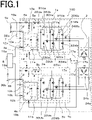
- FIG. 1 is a circuit diagram of the electric rotating machine apparatus 100 according to Embodiment 1.
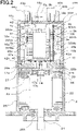
- FIG. 2 is a cross-sectional view of the electric rotating machine apparatus 100 according to Embodiment 1.
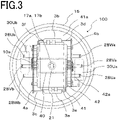
- FIG. 3 is a perspective view of the electric rotating machine apparatus 100 according to Embodiment 1, when viewed from the top side.
- the circuit diagram in FIG. 1 represents an example in which the electric rotating machine apparatus 100 is applied to an electric power steering apparatus.
- the electric rotating machine apparatus 100 has a first control unit 1a, a second control unit 1b, and an electric rotating machine 2 including windings 24a and 24b of two three-phase systems.
- the first control unit 1a and the second control unit 1b has one and the same configuration, and substantially the same components are mounted in each thereof.
- first control unit 1a will be explained, because the same explanation can be applied also to the second control unit 1b.
- the first control unit 1a includes a first control circuit 16a having a first CPU 10a, a first power module 3a for supplying a current to the electric rotating machine 2, a first power-source-relay switching device 5a, and a first filter 6a. From a first battery 9a mounted in a vehicle, a first power-source input 19a and a first ground 36a are connected with the first control unit 1a, and information of turning on an ignition switch 7 is inputted to the first control unit 1a. Moreover, from a sensor group 8, information items from a torque sensor, which is mounted in the vicinity of the handwheel and detects steering torque, a speed sensor, which detects the traveling speed of the vehicle, and the like are inputted to the first control unit 1a.
- the first battery 9a supplies electric power to the first control circuit 16a by way of the first filter 6a; a first power-source output is generated by a first power-source circuit 13a and is supplied to the inside of the first control circuit 16a.
- the information items from the sensor group 8 are transmitted to the first CPU 10a by way of a first input circuit 12a of the first control circuit 16a. Based on those information items, the first CPU 10a calculates and outputs a current value for rotating the electric rotating machine 2.
- the output signal of the first CPU 10a is transmitted to the first power module 3a by way of a first driving circuit 11a included in an output circuit.
- the first driving circuit 11a When receiving a command signal from the first CPU 10a, the first driving circuit 11a outputs driving signals for driving switching devices in the first power module 3a.
- the components of the first control circuit 16a are mounted on a first control circuit board 4a.
- the first driving circuit 11a is mounted to the first control circuit 16a, because only small current flows therein; however, it can be disposed in the first power module 3a. In addition, it may be allowed that the first control circuit 16a contains the first power module 3a and the components of the first power module 3a are mounted on the first control circuit board 4a.
- the first power module 3a mainly includes
- the windings 24a of the respective phases can independently be supplied with currents.
- the respective electric-potential differences across the shunt resistors 33Ua, 33Va, and 33Wa and, for example, the respective voltages of the motor winding terminals are also transmitted to the first input circuit 12a.
- These information items are also inputted to the first CPU 10a; the first CPU 10a calculates the difference between the calculated current value and a detection value and then performs so-called feedback control so as to supply a desired motor current and to assist steering power.
- the first control circuit 16a also outputs a driving signal for the first power-source-relay switching device 5a that supplies the first power-source input 19a to the first power module 3a by way of the first filter 6a.
- the first power-source-relay switching device 5a can cut off current supply to the electric rotating machine 2.
- the electric-rotating-machine relay switching devices 34Ua, 34Va, and 34Wa are also provided in the first power module 3a and can cut off the respective phases.
- the filter 6a including a capacitor and a coil is disposed close to the first power-source input 19a.
- the first control unit 1a has been explained; because the same explanation can be applied to the second control unit 1b, there will be omitted the explanations for a second control circuit board 4b, a second CPU 10b, a second input circuit 12b, a second power-source circuit 13b, and a second driving circuit 11b that are included in a second control circuit 16b, a second power-source-relay switching device 5b, a second filter 6b, and a second power module 3b.
- the first CPU 10a has an abnormality detection function of detecting an abnormality in any one of the sensor group 8, the first driving circuit 11a, the first power module 3a, the motor windings, and the like, based on inputted respective information items; when detecting an abnormality, the first CPU 10a turns off corresponding-phase one of the upper switching devices 31Ua, 31VA, and 31Wa, corresponding one of the lower switching devices 32Ua, 32VA, and 32Wa, and corresponding one of the electric-rotating-machine relay switching devices 34Ua, 34Va, and 34Wa so that for example, current supply only for a predetermined phase is cut off in accordance with the abnormality.
- the power-source-relay switching device 5a is turned off.
- the first CPU 10a and the second CPU 10b are connected with each other by means of a communication line 14 so that they can mutually transmit and receive information; information to be utilized for controlling and information at a time when an abnormality is detected are transmitted and received.
- high-speed data communication such as SPI (Serial Peripheral Interface) communication is utilized.
- SPI Serial Peripheral Interface
- the communication method is not limited to SPI communication.
- the communication line 14 is described with an example of data communication between the first CPU 10a and the second CPU 10b; however, it may be allowed that there is utilized a signal for indicating a state by means of a voltage level such as High level or Low level.
- the signal may be an analogue one.
- the communication line 14 does not connect the CPUs.
- the signal line may connect electronic components to be mounted on the control circuit board.
- the signal line may connect electronic components to be mounted on one of the control circuit boards with a CPU to be mounted on the other thereof.
- the electric rotating machine 2 is a brushless motor in which windings of each of two three-phase systems are delta-connected.
- a first rotation sensor 17a and a second rotation sensor 17b for detecting the rotation position of the rotor of the brushless motor are mounted.
- respective sensors of the two systems are mounted; the rotation information items therefrom are transmitted to the input circuits 12a and 12b of the first control circuit 16a and the second control circuit 16b, respectively.
- the electric rotating machine 2 is not three-phase delta-connected brushless motor but either a three-phase star-connected brushless motor or a motor having dipole-two-pair brushes.
- either distributed winding or concentrated winding can be adopted.
- the electric rotating machine 2 may be a so-called tandem motor having two stators. Even windings of one system or two-system collaboration can be adopted, as far as the configuration can output desired motor rotation speed and torque.
- FIG. 2 is a cross-sectional view of the electric rotating machine apparatus 100 according to Embodiment 1.
- the electric rotating machine apparatus 100 has two-system configuration in which the control circuits 16a and 16b are independent from each other, the power modules 3a and 3b are independent from each other, connectors 43a, 43b, 44a, and 44b are independent from one another, the rotation sensors 17a and 17b are independent from each other, and the winding groups of the electric rotating machine 2 are independent from each other, and so on; thus, the redundancy is secured.
- the control unit 1 is provided at the anti-output side of an output axle 21 of the electric rotating machine 2; the electric rotating machine 2 and the control unit 1 are integrated with each other.
- the maximum outer diameter of the control unit 1 is the same as or smaller than that of the electric rotating machine 2. Accordingly, a structure in which main units are erected in parallel with the output axle 21 is adopted.
- the electric rotating machine 2 mainly includes the output axle 21 incorporated in a case 25, a rotor 23, and a stator 22. Two or more permanent magnets are arranged around the rotor 23; multi-phase windings 24 are wound around the stator 22.
- a ring-shaped terminal unit 27 with which the winding 24 is connected and then extends to the control unit 1 is disposed close to the upper portion of the winding.
- An upper bearing 26a and a lower bearing 26b for making the output axle 21 rotate are arranged at the upper and lower sides, respectively, of the drawing.
- the upper bearing 26a is disposed in the center of a frame 29; the frame 29 is situated at the boundary between the electric rotating machine 2 and the control unit 1 and functions also as a cover for the electric rotating machine 2.
- Each of winding terminal portions 28a and 28b of the motor penetrates the frame 29 from the ring-shaped terminal unit 27 and then extends into the control unit 1.
- Three pieces each of the winding terminal portions of the two systems are collectively extended to the periphery of the inner circumference of the control unit 1.
- the connectors 43a, 43b, 44a, and 44b are arranged at the uppermost portion of the control unit 1; the first filter 6a and the second filter 6b each of which includes a capacitor and a choke coil are mounted nearby the connectors.
- the connectors 43a and 43b are the ones in each of which a relatively large current in the power source system flows; each of the connectors 44a and 44b is the one for a small current in the signal system.
- a bottom portion 41a of the heat sink 41 has the shape of a circle inscribed in the case 25 of the electric rotating machine 2.
- the anti-output-side end of the output axle 21 is extended in the center thereof and a sensor magnet 18 is mounted on the anti-output-side end.
- the sensor magnet 18 has a pair of or two or more pairs of magnetic poles; the first rotation sensor 17a and the second rotation sensor 17b are mounted on the surface, of a sensor circuit board 40, that faces the sensor magnet 18. Rotation of the sensor magnet 18 causes a change in the magnetic field; the first rotation sensor 17a and the second rotation sensor 17b independently detect the rotation of the output axle 21. Based on the outputs of the rotation sensors 17a and 17b, the first CPU 10a and the second CPU 10b, respectively, can comprehend the rotation angle of the output axle 21. In this regard, however, it may be allowed that two rotation sensors are incorporated in a single package.
- FIG. 2 illustrates a configuration in which two rotation sensors are incorporated in a single package.
- the one-package configuration makes it possible to arrange both the first rotation sensor 17a and the second rotation sensor 17b as close to the center of the sensor magnet 18 as possible.
- the power-source lines and the signal lines of the first rotation sensor 17a are connected with electrodes at the bottom-end portion of the first control circuit board 4a through the intermediary of a short first terminal group 37a;
- the power-source lines and the signal lines of the second rotation sensor 17b are connected with electrodes at the bottom-end portion of the second control circuit board 4b through the intermediary of a short second terminal group 37b.
- a hole is provided in the bottom side of the heat sink 41, and the sensor circuit board 40 is fixed in such a way as to be enclosed by the hole.
- the first CPU 10a and the second CPU 10b are connected with each other by means of the communication line 14 (unillustrated in FIG. 2 ) so that they can mutually transmit and receive information; information to be utilized for controlling and information at a time when an abnormality is detected are transmitted to the other party.
- the communication line 14 includes the wiring strip conductors and the electrodes of the sensor circuit board 40, the wiring strip conductors and the electrodes of each of the control circuit boards 4a and 4b, the first terminal group 37a, and the second terminal group 37b.
- the first terminal group 37a is provided in order to provide the first rotation sensor 17a on the sensor circuit board 40 and to transmit a sensor signal to the first control circuit board 4a; the second terminal group 37b is provided in order to provide the second rotation sensor 17b on the sensor circuit board 40 and to transmit a sensor signal to the second control circuit board 4b. Accordingly, it is advantageous that the communication line 14 can be secured only by adding the terminals, without providing any extra terminal group.
- the first terminal group 37a and the second terminal group 37b are attached to the respective electrode groups at the bottom-end potions of the first control circuit board 4a and the second control circuit board 4b, respectively; with short distances, the respective electrode groups are connected with each corresponding one of the electrode groups at the both ends of the sensor circuit board 40.
- the first control circuit board 4a, the second control circuit board 4b, and the sensor circuit board 40 are arranged in such a way as to form an angular U-shape; by use of the end portions of the boards on which no component is mounted, the boards are electrically connected. It is advantageous that such arrangement makes it possible to make efficient connection, while securing an effective area for mounting the components of the first control circuit board 4a, the second control circuit board 4b, and the sensor circuit board 40.
- the first terminal group 37a is mounted on the bottom-end portion of the first control circuit board 4a and on one of the both end portion of the sensor circuit board and that the second terminal group 37b is mounted on the bottom-end portion of the second control circuit board 4b and on the other one of the both end portion of the sensor circuit board 40.
- the first terminal group 37a and the second terminal group 37b are mounted on the respective places where the first control circuit board 4a and the second control circuit board 4b, respectively, close to the sensor circuit board 40, it is made possible that the connection can be made with a short terminal.
- the first control circuit board 4a, the second control circuit board 4b, and the sensor circuit board 40 are arranged in such a way as to form an angular U-shape; however, it is also made possible that the first control circuit board 4a, the second control circuit board 4b, and the sensor circuit board 40 are arranged in such a way as to form an H-shape and that the first terminal group 37a and the second terminal group 37b are mounted on respective places other than the bottom-end portions of the first control circuit board 4a and the second control circuit board 4b, respectively.
- the width of the sensor circuit board 40 is set to be larger than the distance between the first control circuit board 4a and the second control circuit board 4b and that the first terminal group 37a and the second terminal group 37b are mounted on respective places other than the both end portions of the sensor circuit board 40.
- the first power-source input 19a and the first signal line 44c from the connectors 43a and 44a, respectively, are electrically connected with the first control circuit board 4a; the second power-source input 19b and the second signal line 44d from the connectors 43b and 44b, respectively, are electrically connected with the second control circuit board 4b.
- the first power-source input 19a and the second power-source input 19b are connected by way of the first filter 6a and the second filter 6b, respectively, as represented in the circuit diagram in FIG. 1 ; electric power is supplied through a bus bar of a relay member 42 attached to the heat sink 41.
- This bus bar also incorporates a first extension terminal 42a of a first output terminal 3e of the first power module 3a and a second extension terminal 42b of a second output terminal 3f (unillustrated in FIG. 2 ) of the second power module 3b. It is made possible that the bus bar of the relay member 42 is set to have a free shape and extend in any direction. Meanwhile, the first signal line 44c is connected with the first input circuit 12a of the first control circuit board 4a; the second signal line 44d is connected with the second input circuit 12b of the second control circuit board 4b (12a and 12b are unillustrated in FIG. 2 ).
- the capacitors 30Ua, 30Va, and 30Wa are arranged at the outer circumferential side in such a way as to be substantially in parallel with the first control circuit board 4a and to be stacked vertically; the capacitors 30Ub, 30Vb, and 30Wb are arranged at the outer circumferential side in such a way as to be substantially in parallel with the second control circuit board 4b and to be stacked vertically.
- the respective terminals of the capacitors are connected with the power-source lines of the relay member 42 or the power-source lines wired on the power module 3a or 3b; the main bodies of the capacitors are fixed by supporting member 45a or 45b.
- FIG. 3 is a perspective view of the electric rotating machine apparatus 100 according to Embodiment 1, when viewed from the top side.
- FIG. 3 is a perspective view illustrating principal parts viewed from the connectors; the heat sink 41 whose columnar portion is substantially rectangular-parallelopiped is disposed in the center; the first control circuit board 4a and the second control circuit board 4b are arranged along the respective long sides of the rectangular parallelopiped, and the first power module 3a and the second power module 3b are arranged in such a way as to adhere to the respective short sides thereof.
- a first signal line 3c of the first power module 3a is connected with the first control circuit board 4a; a second signal line 3d of the second power module 3b is connected with the second control circuit board 4b.
- the heat sink 41, the first control circuit board 4a, the second control circuit board 4b, the first power module 3a and the second power module 3b are arranged axisymmetric with respect to the output axle 21.
- Winding terminal portions 28Ua, 28Va, and 28Wa are arranged at the outer circumference side of the first control circuit board 4a and are connected with the first output terminal 3e of the first power module 3a through the extension terminal 42; winding terminal portions 28Ub, 28Vb, and 28Wb are arranged at the outer circumference side of the second control circuit board 4b and are connected with the second output terminal 3f of the second power module 3b through the extension terminal 42.
- the sensor circuit board 40 is disposed in the hole that penetrates the bottom portion of the heat sink 41.
- the portion of the control unit 1 in the vicinity of the electric rotating machine 2 is utilized as connection positions of the winding terminal portions 28Ua, 28Va, 28Wa, 28Ub, 28Vb, and 28Wb; in the upper portion thereof, the capacitors 30Ua, 30Ub, and the like are stacked.
- the sensor circuit board 40 is incorporated in a hole in the bottom portion of the heat sink 41, the space is utilized with contrivance and hence downsizing is achieved.
- the components that generate large heat are made to adhere to the heat sink and the other components are made to be apart from the heat sink, so that heat radiation is improved.
- the first control circuit board 4a and the first power module 3a are arranged along the respective sides of the heat sink in such a way as to be adjacent to each other, and the second control circuit board 4b and the second power module 3b are arranged along the respective sides of the heat sink in such a way as to be adjacent to each other; as a result, the control circuit boards 4a and 4b and the power modules 3a and 3b of the two systems are each separated and independent from each other for each of the systems. Moreover, because the control circuit boards 4a and 4b and the power modules 3a and 3b are arranged axisymmetric with respect to the output axle 21, any one of the systems can be connected with the three-phase terminal portions of the motor.
- Two kinds of connectors i.e., a connector for the power-source system and a connector for the signal system are provided; however, it may be allowed that one kind of connector is utilized and is separated into the power-source system and the signal system in the control unit.
- the electric rotating machine apparatus 100 according to Embodiment 1 includes
- the arrangement of the members is contrived, the spaces in the control units 1a and 1b can effectively be utilized and hence downsizing can be achieved. Because the respective systems having the same shape and configuration are formed separately and independently from each other, the redundancy can be secured and the heat-radiation performance can be improved.
- the first control circuit board 4a and the second control circuit board 4b are separated from each other so as to be different bodies, and the first control circuit board 4a and the second control circuit board 4b are connected by the communication line 14 through the intermediary of the sensor circuit board 40, so that the first terminal group 37a and the second terminal group 37b, which are connection portions, are downsized and hence Embodiment 1 contributes to cost reduction.
- the first terminal group 37a and the second terminal group 37b are originally necessary components for transmitting sensor signals to the first control circuit board 4a and the second control circuit board 4b; because the communication line 14 can be secured by utilizing these components and adding terminals, Embodiment 1 contributes to downsizing and cost reduction.
- the first control circuit board 4a, the second control circuit board 4b, and the sensor circuit board 40 are arranged in such a way as to form an angular U-shape; the first terminal group 37a connects the electrodes at the bottom-end portion of the first control circuit board 4a with the electrodes at one end of the sensor circuit board 40; the second terminal group 37b connects the electrodes at the bottom-end portion of the second control circuit board 4b with the electrodes at the other end of the sensor circuit board 40.
- the arrangement that achieves electrical connection between the boards by use of the end portions of the boards on each of which no component is mounted makes it possible that while the effective area for mounting the first control circuit board 4a, the second control circuit board 4b, and the sensor circuit board 40 is secured, efficient connection is achieved.
- the sensors 17a and 17b for detecting the rotation angle of the electric rotating machine 2 are provided on the sensor circuit board. Because such arrangement makes it possible to accurately manage the distance between the output axle of the electric rotating machine and the sensors 17a and 17b, the rotation angle of the output axle can accurately be detected. Because accurate detection of the rotation angle of the output axle makes it possible to optimize the timing of application of a current to the winding of the electric rotating machine, the performance of the electric rotating machine apparatus can be raised.
- FIG. 4 is a circuit diagram of an electric rotating machine apparatus 101 according to Embodiment 2.
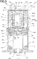
- FIG. 5 is a cross-sectional view of the electric rotating machine apparatus 101 according to Embodiment 2.
- FIGS. 4 and 5 of Embodiment 2 are different from FIGS. 1 and 2 in that a first temperature sensor 55a and a second temperature sensor 55b are provided on a sensor circuit board 60.
- the first temperature sensor 55a and the second temperature sensor 55b illustrated in each of FIGS. 4 and 5 are arranged on the sensor circuit board 60 so as to measure the temperature of the vicinity of the electric rotating machine 2.
- the first temperature sensor 55a and the second temperature sensor 55b each measure the temperature of the electric rotating machine 2 and then output the measured temperature values to a first control unit 61a and a second control unit 61b, respectively. It may be allowed that two or more pieces each of the first temperature sensors 55a and the second temperature sensor 55b are provided for the respective systems. It may be allowed that two temperature sensors are incorporated in a single package.
- FIG. 5 illustrates a configuration in which two temperature sensors are incorporated in a single package.
- the electric rotating machine apparatus 101 it is required to monitor or estimate the temperature and then limit the current so that at a time of energization, the temperature of each of the portions falls with the rating. Because suggesting limitation of the output, limitation of the current directly links with the merchantability. Accordingly, it is required to apply a maximally large current that is within the rating. Accordingly, accurate measurement of the temperatures of the respective portions makes it possible to energize up to the limitation of the energization; thus, the performance of the electric rotating machine 2 can be raised.
- the winding 24 of the electric rotating machine 2 or the motor magnet of the electric rotating machine 2 is a temperature-monitoring subject, because the temperature thereof rises due to application of the current. Therefore, it is important that in order to measure the temperature of the electric rotating machine 2, the first temperature sensor 55a and the second temperature sensor 55b are arranged at the positions that are as close to the electric rotating machine 2 as possible. As each of the first temperature sensor 55a and the second temperature sensor 55b, a thermistor or the like is utilized.
- the sensor circuit board 60 is close to the electric rotating machine 2; therefore, mounting the first temperature sensor 55a and the second temperature sensor 55b on the sensor circuit board 60 makes it possible to accurately measure the temperature of the vicinity of the motor.
- FIG. 5 it may be allowed that the side of the sensor circuit board 60 on which the first temperature sensor 55a and the second temperature sensor 55b are arranged and the side thereof on which the first rotation sensor 17a and the second rotation sensor 17b are arranged are reversed each other.
- the first temperature sensor 55a, the second temperature sensor 55b, the first rotation sensor 17a, and the second rotation sensor 17b are all mounted on any one of the sides.
- FIG. 6 is a top view of a sensor circuit board 70 of an electric rotating machine apparatus according to Embodiment 3.
- the top surface of the sensor circuit board 70 faces the sensor magnet 18 at the axle end of the output axle 21 of the electric rotating machine 2.
- a first communication line 14a and a second communication line 14b are symmetrically arranged with respect to the first rotation sensor 17a and the second rotation sensor 17b.
- the communication between the first CPU 10a and the second CPU 10b can be realized even with a single communication line.
- the upward and downward communication lines are separately provided, so that the instantaneousness of the communication can be secured. It may be allowed that two or more communication lines are secured for each of the upward communication and the downward communication.
- the first rotation sensor 17a and the second rotation sensor 17b are mounted on the central portion of the sensor circuit board 70. This is because the distances among the sensor magnet 18 at the axle end of the output axle 21 of the electric rotating machine 2, the first rotation sensor 17a, and the second rotation sensor 17b are managed so that the rotation is accurately detected. As a result, the detecting accuracy for the first rotation sensor 17a and the second rotation sensor 17b can be raised. Providing the first rotation sensor 17a and the second rotation sensor 17b on the central portion of the sensor circuit board 70 makes it possible to accurately set the position thereof with respect to the sensor magnet by finely adjusting the mounting position of the sensor circuit board 70.
- FIG. 6 there has been explained the case where the first rotation sensor 17a and the second rotation sensor 17b are provided on the sensor circuit board 70; however, the same explanation can be applied to the case where the first temperature sensor 55a and the second temperature sensor 55b are provided thereon. This is because providing the first temperature sensor 55a and the second temperature sensor 55b on the central portion of the sensor circuit board 70 makes it possible to detect the temperature of the vicinity of the output axle 21, which is a temperature representative point of the electric rotating machine 2.
- Embodiment 3 can also contribute to downsizing of the sensor circuit board 70, resulting in cost reduction.
- Arranging the two, i.e., the upward and downward communication lines symmetrically with respect to the first rotation sensor 17a and the second rotation sensor 17b makes it possible that the first communication line 14a, the second communication line 14b, a first-rotation-sensor communication line 17c, and a second-rotation-sensor communication line 17d are provided spaced apart from one another, in a balanced manner; thus, the mounting area of the sensor circuit board 70 can effectively be utilized, while superimposition of noise is prevented.
- FIG. 6 there has been explained the case where the first rotation sensor 17a and the second rotation sensor 17b are provided on the sensor circuit board 70; however, the same explanation can be applied to the case where the first temperature sensor 55a and the second temperature sensor 55b are provided on the central portion of the sensor circuit board 70.
- Arranging the two, i.e., the upward and downward communication lines symmetrically with respect to the first temperature sensor 55a and the second temperature sensor 55b makes it possible that the first communication line 14a, the second communication line 14b, a first-temperature-sensor communication line 55c, and a second-temperature-sensor communication line 55d are provided spaced apart from one another, in a balanced manner; thus, the mounting area of the sensor circuit board 70 can effectively be utilized, while superimposition of noise is prevented.
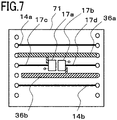
- FIG. 7 is a top view of a sensor circuit board 71 according to Embodiment 4.
- the top surface of the sensor circuit board 71 faces the sensor magnet 18 at the axle end of the output axle 21 of the electric rotating machine 2.
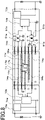
- FIG. 8 is a board configuration diagram related to the communication lines 14a and 14b according to Embodiment 4; the respective boards to be connected with one another in an angular U-shape are developed on a plane, and the flows of signals are explained.
- the first rotation sensor 17a and the second rotation sensor 17b are mounted on the central portion of the sensor circuit board 71, and each of the first-rotation-sensor communication line 17c and the second-rotation-sensor communication line 17d is provided in such a way as to traverse the central portion of the sensor circuit board 71.
- the first communication line 14a and the second communication line 14b are provided in the peripheral area of the sensor circuit board 71; a first ground 36a is disposed between the communication line 14a and the first-rotation-sensor and second-rotation-sensor communication lines 17c and 17d; a second ground 36b is disposed between the communication line 14b and the first-rotation-sensor and second-rotation-sensor communication lines 17c and 17d.
- the first rotation sensor 17a and the second rotation sensor 17b are described; however, this description can be applied to the first temperature sensor 55a and the second temperature sensor 55b.
- the first temperature sensor 55a and the second temperature sensor 55b are arranged at the center of the sensor circuit board 71; the first communication line 14a and the second communication line 14b are provided in the peripheral area of the sensor circuit board 71; respective ground lines are arranged between the first-temperature-sensor and second-temperature-sensor communication lines 55c and 55d and the communication line 14a and between the first-temperature-sensor and second-temperature-sensor communication lines 55c and 55d and the communication line 14b; as a result, noise can be reduced.
- FIG. 8 represents an example in which in the case where the respective pairs of the power source and the ground of a first control circuit board 74a and a second control circuit board 74b are separated from each other, the communication is established in such a way that the communication line 14a is equipped with isolators 51a and 51c and the communication line 14b is equipped with isolators 51b and 51d so that the first CPU 10a and the second CPU 10b can interchange information items.
- Each of the isolators 51a, 51b, 51c, and 51d in the present embodiment signifies a signal isolator having a function of isolating an input signal from an output signal; there exist methods in each of which a photo-coupler, a capacitor, an inductance, or the like is utilized.
- the isolators 51a, 51b, 51c, and 51d are mounted on the second control circuit board 4b; however, the isolators 51a and 51c function as a pair and the isolators 51b and 51d function as a pair.
- the signal isolator a photo-coupler is assumed; the signal isolator may be described as a block for each function.
- the first power-source circuit 13a supplies a power source to the isolators 51a and 51b; the second power-source circuit 13b supplies a power source to the isolators 51b and 51d.
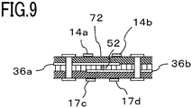
- FIG. 9 is a cross-sectional view of a sensor circuit board 72 according to Embodiment 5.
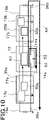
- FIG. 10 is a board configuration diagram related to the communication lines 14a and 14b according to Embodiment 5; the respective boards to be connected with one another in an angular U-shape are developed in a plane, and the flows of signals are explained.
- FIG. 9 illustrates an example in which four printed-wiring layers are provided.
- the first ground 36a and the second ground 36b are printed inside the sensor circuit board 72, grounds are arranged between the first and second communication lines 14a and 14b formed on the top surface and the first-rotation-sensor and second-rotation-sensor communication lines 17c and 17d formed on the bottom surface. Accordingly, although in FIG. 9 , because the first ground 36a and the second ground 36b are printed inside the sensor circuit board 72, grounds are arranged between the first and second communication lines 14a and 14b formed on the top surface and the first-rotation-sensor and second-rotation-sensor communication lines 17c and 17d formed on the bottom surface. Accordingly, although in FIG.
- the respective ground lines are arranged in a planar manner between the communication line 14a and the rotation-sensor signal lines 17c and 17d and between the communication line 14b and the rotation-sensor signal lines 17c and 17d, the grounds are sterically arranged between the communication lines 14a and 14b and the rotation-sensor signal lines 17c and 17d in FIG. 9 .
- a shielding effect is exerted by arranging the ground lines therebetween as illustrated in FIG. 9 and hence crosstalk can be prevented from occurring between the rotation-sensor communication lines 17c and 17d and the communication lines 14a and 14b; this effect is the same as that in FIG. 7 according to Embodiment 4. Malfunctions can also be prevented by reducing noise in each of the signals.
- first rotation sensor 17a and the second rotation sensor 17b are described; however, this description can be applied to the first temperature sensor 55a and the second temperature sensor 55b.
- first temperature sensor 55a and the second temperature sensor 55b are mounted on the bottom surface of the sensor circuit board 71, respective ground lines are arranged between the first and second communication lines 14a and 14b formed on the top surface thereof and the first-temperature-sensor and second-temperature-sensor communication lines 55c and 55d formed on the bottom surface thereof; as a result, noise can be reduced.
- FIG. 10 is a board configuration diagram related to the communication lines 14a and 14b according to Embodiment 5; an isolator 51 is mounted on the sensor circuit board 72.
- FIG. 10 represents the first communication line 14a between a first control circuit board 77a and a second control circuit board 77b; a signal is transmitted to the second control circuit board 77b by way of the isolator 51.
- the description for the second communication line 14b is omitted.
- FIG. 10 there is described a case where as the isolator 51, a coupling-method isolator formed of a capacitor is utilized.
- the isolator 51 performs direct-current isolation, noise as an AC signal may intrude into a signal circuit 50b from a signal circuit 50a.
- the EMI performance is deteriorated if no return path through which the signal returns is provided.
- noise as an AC signal intrudes into the signal circuit 50b from the signal circuit 50a and then propagates through the second ground 36b and the first ground 36a, the noise is scattered. Therefore, the EMI performance is deteriorated.
- FIG. 9 illustrates the case where the return-path capacitive component 52 is formed of the ground strip conductors of the sensor circuit board 72.
- the respective layers of the first ground 36a and the second ground 36b are formed at the upper and lower portion of the multi-layer substrate in such a way as to insert an insulating layer therebetween.
- the arrangement of the respective layers with the insulating layer inserted therebetween causes capacitive coupling that functions as a capacitor.
- FIG. 11 is a top view of a sensor circuit board 73 according to Embodiment 6.
- the top surface of the sensor circuit board 73 faces the sensor magnet 18 at the axle end of the output axle 21 of the electric rotating machine 2.
- FIG. 12 is a board configuration diagram related to the communication lines 14a and 14b according to Embodiment 6; the respective boards to be connected with one another in an angular U-shape are developed on a plane, and the flows of signals are explained.
- the isolators 51a and 51c are provided in the first communication line 14a, and the isolators 51b and 51d are provided in the second communication line 14b.
- the communication can be established in such a way that the communication line 14a is equipped with isolators 51a and 51c and the communication line 14b is equipped with isolators 51b and 51d so that the first CPU 10a and the second CPU 10b can interchange information items.
- Each of the isolators 51a, 51b, 51c, and 51d in the present embodiment signifies a signal isolator having a function of isolating an input signal from an output signal; there exist methods in each of which a photo-coupler, a capacitor, an inductance, or the like is utilized.
- the isolators 51a and 51c function as a pair and the isolators 51b and 51d function as a pair.
- the signal isolator a photo-coupler is assumed, and the explanation is made with blocks that each include a pair of isolators; however, as is the case with the isolator 51 in FIG. 10 , the signal isolator may be described as a block for each function.
- the isolators 51a, 51b, 51c, and 51d can be provided on either the first control circuit board or the second control circuit board.
- FIG. 8 represents the case where the isolators 51a, 51b, 51c, and 51d are provided on the second control circuit board 74b.
- the isolators 51a, 51b, 51c, and 51d are provided in the sensor circuit board 73, mounting of the isolators 51a, 51b, 51c, and 51d on the first control circuit board 75a or the second control circuit board 75b can be avoided, as represented in FIG. 12 .
- the mounting area thereof has no enough margin; because the second CPU 10b, the second power-source circuit 13b, and many other components are mounted on the second control circuit board 75b, the mounting area thereof has no enough margin.
- the first rotation sensor 17a, the second rotation sensor 17b, the first temperature sensor 55a, the second temperature sensor 55b, the first terminal group 37a, the second terminal group 37b, and the like may be mounted on the sensor circuit board 73.
- the isolators 51a, 51b, 51c, and 51d are mounted on the sensor circuit board 73, it is made possible to take mounting balance among the boards and to achieve downsizing of the overall electric rotating machine apparatus and cost reduction.
- the pair of the isolators 51a and 51c and the pair of isolators 51b and 51d on the sensor circuit board 73 are connected with the first communication line 14a and the second communication line 14b, respectively.
- the isolator can be applied also to each of the first rotation sensor 17a, the second rotation sensor 17b, the first temperature sensor 55a, and the second temperature sensor 55b.
- the signal is transmitted by way of the isolator, so that even when the power source and the ground for the first control circuit board 75a are each separated from the power source and the ground for the first control circuit board 75a, the sensor signal can correctly be received.
- the first rotation sensor 17a and the second rotation sensor 17b are mounted on the central portion of the sensor circuit board 73. This is because the distances among the sensor magnet 18 at the axle end of the output axle 21 of the electric rotating machine 2, the first rotation sensor 17a, and the second rotation sensor 17b are managed so that the rotation is accurately detected. Then, the isolators 51a, 51b, 51c, and 51d are mounted on the outer peripheral portion of the sensor circuit board 73, where no component is mounted.
- the isolators 51a, 51b, 51c, and 51d on the outer peripheral portion of the sensor circuit board 73 results in arrangement of the two, i.e., the upward and downward communication lines on the outer peripheral portion of the sensor circuit board 73, it is made possible that the first communication line 14a, the second communication line 14b, the first-rotation-sensor communication line 17c, and the second-rotation-sensor communication line 17d are provided spaced apart from one another and in a balanced manner; thus, the mounting area of the sensor circuit board 73 can effectively be utilized, while superimposition of noise is prevented.
- the first rotation sensor 17a and the second rotation sensor 17b are mounted on the central portion of the sensor circuit board 73, and the isolators 51a and 51c and the isolators 51b and 51d are symmetrically mounted with respect to the first rotation sensor 17a and the second rotation sensor 17b.
- the isolators 51a, 51b, 51c, and 51d in such a manner results in arranging the two, i.e., the upward and downward communication lines spaced evenly apart from each other on the outer peripheral portion of the sensor circuit board 73, it is made possible that the first communication line 14a, the second communication line 14b, the first-rotation-sensor communication line 17c, and the second-rotation-sensor communication line 17d are provided spaced apart from one another and in a balanced manner; thus, the mounting area of the sensor circuit board 73 can effectively be utilized, while superimposition of noise is prevented.
- the first rotation sensor 17a and the second rotation sensor 17b are described; however, this description can be applied to the first temperature sensor 55a and the second temperature sensor 55b.
- the first temperature sensor 55a and the second temperature sensor 55b are arranged on the central portion of the sensor circuit board 73, and the isolators 51a and 51c and the isolators 51b and 51d are mounted at the outsides of the first temperature sensor 55a and the second temperature sensor 55b, respectively, or in a symmetrical manner so that distances among the components are secured; thus, the mounting area of the sensor circuit board 73 can effectively be utilized, while intrusion of noise is prevented.
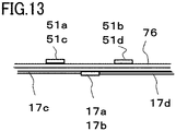
- FIG. 13 is a cross-sectional view of a sensor circuit board 76 according to Embodiment 7.
- the first and second rotation sensors 17a and 17b and the isolators 51a, 51b, 51c, and 51d are mounted on the respective opposite sides of the sensor circuit board 76.
- first and second rotation sensors 17a and 17b and the isolators 51a, 51b, 51c, and 51d mounted on the respective opposite sides of the sensor circuit board 76 makes it possible that the isolators 51a, 51b, 51c, and 51d are separated as much as possible from the first and second rotation sensors 17a and 17b and hence noise is prevented from intruding into the first and second rotation sensors 17a and 17b.
- the first rotation sensor 17a and the second rotation sensor 17b are described; however, this description can be applied to the first temperature sensor 55a and the second temperature sensor 55b. Also with regard to the temperature sensors, mounting the temperature sensors 55a and 55b and the isolators 51a, 51b, 51c, and 51d on the respective opposite sides of the sensor circuit board 76 makes it possible that the distances among the components are secured and hence intrusion of noise is prevented.
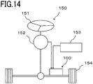
- FIG. 14 is a configuration diagram of an electric power steering apparatus 150 according to Embodiment 8. By use of FIG. 14 , there will be explained an example in which the electric rotating machine apparatus 100 is applied to the electric power steering apparatus 150 to be mounted in a vehicle.
- FIG. 14 is an overall configuration diagram of the electric power steering apparatus 150 and illustrates an example of a rack-type electric power steering apparatus.
- a torque sensor 152 detects the steering torque and then outputs it to the electric rotating machine apparatus 100.
- a speed sensor 153 detects the traveling speed of the vehicle and then outputs it to the electric rotating machine apparatus 100. Based on the inputs from the torque sensor 152 and the speed sensor 153, the electric rotating machine apparatus 100 generates auxiliary torque for supplementing the steering torque and then supplies it to the steering mechanism of front wheels 154 of the vehicle.
- the torque sensor 152 and the speed sensor 153 are included in the sensor group 8 in FIG. 1 .
- the electric rotating machine apparatus 100 may generate auxiliary torque based on inputs other than the inputs from the torque sensor 152 and the speed sensor 153. Downsizing of an electric rotating machine apparatus to be applied to an electric power steering apparatus raises the mountability of the electric rotating machine apparatus for the vehicle.
Landscapes
- Engineering & Computer Science (AREA)
- Power Engineering (AREA)
- Microelectronics & Electronic Packaging (AREA)
- Power Steering Mechanism (AREA)
Applications Claiming Priority (1)
| Application Number | Priority Date | Filing Date | Title |
|---|---|---|---|
| PCT/JP2019/045037 WO2021100075A1 (fr) | 2019-11-18 | 2019-11-18 | Dispositif de machine électrique tournante et dispositif de direction assistée électrique |
Publications (2)
| Publication Number | Publication Date |
|---|---|
| EP4064533A1 true EP4064533A1 (fr) | 2022-09-28 |
| EP4064533A4 EP4064533A4 (fr) | 2022-11-23 |
Family
ID=75981508
Family Applications (1)
| Application Number | Title | Priority Date | Filing Date |
|---|---|---|---|
| EP19953252.4A Pending EP4064533A4 (fr) | 2019-11-18 | 2019-11-18 | Dispositif de machine électrique tournante et dispositif de direction assistée électrique |
Country Status (5)
| Country | Link |
|---|---|
| US (1) | US12101004B2 (fr) |
| EP (1) | EP4064533A4 (fr) |
| JP (1) | JP7361789B2 (fr) |
| CN (1) | CN114731103B (fr) |
| WO (1) | WO2021100075A1 (fr) |
Families Citing this family (4)
| Publication number | Priority date | Publication date | Assignee | Title |
|---|---|---|---|---|
| EP4167713A4 (fr) * | 2020-06-19 | 2024-09-11 | Milwaukee Electric Tool Corporation | Taille-bordure |
| US20250233491A1 (en) * | 2021-11-04 | 2025-07-17 | Mitsubishi Electric Corporation | Electric rotating machine apparatus and electric power steering apparatus |
| US20240066995A1 (en) * | 2022-08-23 | 2024-02-29 | Black & Decker Inc. | Motor control panel for electric lawn apparatus |
| JP2025096788A (ja) * | 2023-12-18 | 2025-06-30 | 株式会社デンソー | モータ制御装置 |
Family Cites Families (20)
| Publication number | Priority date | Publication date | Assignee | Title |
|---|---|---|---|---|
| JPH10135588A (ja) | 1996-10-25 | 1998-05-22 | Unisia Jecs Corp | 集積回路基板 |
| JP5287787B2 (ja) * | 2010-04-16 | 2013-09-11 | 株式会社デンソー | 電動装置 |
| JP5647926B2 (ja) | 2011-03-29 | 2015-01-07 | カヤバ工業株式会社 | 蓄電装置 |
| JP5594312B2 (ja) * | 2012-04-02 | 2014-09-24 | 株式会社デンソー | モータ駆動装置 |
| JP2015079649A (ja) | 2013-10-17 | 2015-04-23 | 株式会社デンソー | 電池状態監視システム |
| JP6123848B2 (ja) * | 2014-07-31 | 2017-05-10 | 株式会社デンソー | 駆動装置、および、これを用いた電動パワーステアリング装置 |
| JP6179476B2 (ja) * | 2014-07-31 | 2017-08-16 | 株式会社デンソー | 駆動装置、および、これを用いた電動パワーステアリング装置 |
| JP6223593B2 (ja) * | 2014-10-22 | 2017-11-01 | 三菱電機株式会社 | 電動パワーステアリング装置 |
| JP2016118500A (ja) * | 2014-12-22 | 2016-06-30 | 日本精工株式会社 | 回転角度センサ及びそれを備えたブラシレスモータ並びにそれを搭載した電動パワーステアリング装置及び車両 |
| JP6427443B2 (ja) | 2015-03-12 | 2018-11-21 | 日立オートモティブシステムズ株式会社 | モータの駆動制御ユニット |
| CN108093671B (zh) * | 2015-09-18 | 2021-07-06 | 三菱电机株式会社 | 一体型电动助力转向装置 |
| JP6514135B2 (ja) | 2016-03-09 | 2019-05-15 | 日立オートモティブシステムズ株式会社 | 電動駆動装置及び電動パワーステアリング装置 |
| JP6522536B2 (ja) | 2016-03-09 | 2019-05-29 | 日立オートモティブシステムズ株式会社 | 電動駆動装置及び電動パワーステアリング装置 |
| JP6680054B2 (ja) | 2016-04-06 | 2020-04-15 | 株式会社デンソー | 駆動装置、および、これを用いた電動パワーステアリング装置 |
| JP6819185B2 (ja) * | 2016-09-27 | 2021-01-27 | セイコーエプソン株式会社 | 液体吐出装置 |
| JP7027808B2 (ja) * | 2016-11-11 | 2022-03-02 | 株式会社デンソー | 回転電機制御装置、および、これを用いた電動パワーステアリング装置 |
| JP6852573B2 (ja) * | 2017-06-01 | 2021-03-31 | 日本精工株式会社 | 電動駆動装置及び電動パワーステアリング装置 |
| JP2019041507A (ja) | 2017-08-25 | 2019-03-14 | 株式会社ジェイテクト | モータ装置 |
| EP3691092B1 (fr) | 2017-09-28 | 2021-09-15 | Mitsubishi Electric Corporation | Dispositif de direction assistée électrique |
| CN111183570B (zh) * | 2017-10-13 | 2022-07-08 | 三菱电机株式会社 | 电动助力转向装置 |
-
2019
- 2019-11-18 CN CN201980102216.XA patent/CN114731103B/zh active Active
- 2019-11-18 US US17/766,676 patent/US12101004B2/en active Active
- 2019-11-18 WO PCT/JP2019/045037 patent/WO2021100075A1/fr not_active Ceased
- 2019-11-18 JP JP2021558038A patent/JP7361789B2/ja active Active
- 2019-11-18 EP EP19953252.4A patent/EP4064533A4/fr active Pending
Also Published As
| Publication number | Publication date |
|---|---|
| CN114731103B (zh) | 2025-11-25 |
| US12101004B2 (en) | 2024-09-24 |
| JP7361789B2 (ja) | 2023-10-16 |
| EP4064533A4 (fr) | 2022-11-23 |
| WO2021100075A1 (fr) | 2021-05-27 |
| JPWO2021100075A1 (fr) | 2021-05-27 |
| CN114731103A (zh) | 2022-07-08 |
| US20240072614A1 (en) | 2024-02-29 |
Similar Documents
| Publication | Publication Date | Title |
|---|---|---|
| EP3441285B1 (fr) | Dispositif de direction assistée électrique | |
| US12155276B2 (en) | Electric power steering apparatus | |
| US11345397B2 (en) | Driving device and electric power steering apparatus using the same | |
| CN107404196B (zh) | 驱动设备以及使用该驱动设备的电动助力转向设备 | |
| US11565741B2 (en) | Electric power steering device | |
| US12101004B2 (en) | Electric rotating machine apparatus and electric power steering apparatus | |
| US10923992B2 (en) | Drive device and electric power steering device using same | |
| CN107509392B (zh) | 电机的驱动控制单元 | |
| US11387716B2 (en) | Redundant circuit device | |
| US11370373B2 (en) | Power source system | |
| CN110612243B (zh) | 电动助力转向装置 | |
| CN111971880B (zh) | 电动助力转向装置 | |
| US12238857B2 (en) | Electronic control device | |
| US20250233491A1 (en) | Electric rotating machine apparatus and electric power steering apparatus | |
| US12184128B2 (en) | Electric rotating machine apparatus and electric power steering apparatus | |
| WO2024209577A1 (fr) | Dispositif d'entraînement et dispositif de direction assistée électrique |
Legal Events
| Date | Code | Title | Description |
|---|---|---|---|
| STAA | Information on the status of an ep patent application or granted ep patent |
Free format text: STATUS: THE INTERNATIONAL PUBLICATION HAS BEEN MADE |
|
| PUAI | Public reference made under article 153(3) epc to a published international application that has entered the european phase |
Free format text: ORIGINAL CODE: 0009012 |
|
| STAA | Information on the status of an ep patent application or granted ep patent |
Free format text: STATUS: REQUEST FOR EXAMINATION WAS MADE |
|
| 17P | Request for examination filed |
Effective date: 20220420 |
|
| AK | Designated contracting states |
Kind code of ref document: A1 Designated state(s): AL AT BE BG CH CY CZ DE DK EE ES FI FR GB GR HR HU IE IS IT LI LT LU LV MC MK MT NL NO PL PT RO RS SE SI SK SM TR |
|
| REG | Reference to a national code |
Ref country code: DE Ref legal event code: R079 Free format text: PREVIOUS MAIN CLASS: H02K0029080000 Ipc: H02K0011215000 |
|
| A4 | Supplementary search report drawn up and despatched |
Effective date: 20221025 |
|
| RIC1 | Information provided on ipc code assigned before grant |
Ipc: H05K 1/02 20060101ALI20221019BHEP Ipc: H02K 11/40 20160101ALI20221019BHEP Ipc: H02K 11/27 20160101ALI20221019BHEP Ipc: H02K 11/33 20160101ALI20221019BHEP Ipc: H02K 11/25 20160101ALI20221019BHEP Ipc: H02K 11/215 20160101AFI20221019BHEP |
|
| DAV | Request for validation of the european patent (deleted) | ||
| DAX | Request for extension of the european patent (deleted) |