EP4064535A1 - Mécanisme de commande d'entraînement de moteur à engrenages - Google Patents
Mécanisme de commande d'entraînement de moteur à engrenages Download PDFInfo
- Publication number
- EP4064535A1 EP4064535A1 EP20891061.2A EP20891061A EP4064535A1 EP 4064535 A1 EP4064535 A1 EP 4064535A1 EP 20891061 A EP20891061 A EP 20891061A EP 4064535 A1 EP4064535 A1 EP 4064535A1
- Authority
- EP
- European Patent Office
- Prior art keywords
- permanent magnet
- rotating part
- electric motor
- control mechanism
- geared motor
- Prior art date
- Legal status (The legal status is an assumption and is not a legal conclusion. Google has not performed a legal analysis and makes no representation as to the accuracy of the status listed.)
- Pending
Links
- 230000007246 mechanism Effects 0.000 title claims abstract description 100
- 230000008859 change Effects 0.000 claims abstract description 35
- 230000000694 effects Effects 0.000 description 14
- 238000004804 winding Methods 0.000 description 11
- 230000004907 flux Effects 0.000 description 9
- 239000000463 material Substances 0.000 description 6
- 230000005405 multipole Effects 0.000 description 5
- 238000010586 diagram Methods 0.000 description 4
- 238000012423 maintenance Methods 0.000 description 4
- 230000007423 decrease Effects 0.000 description 3
- 238000004519 manufacturing process Methods 0.000 description 3
- 230000002238 attenuated effect Effects 0.000 description 2
- 230000006835 compression Effects 0.000 description 2
- 238000007906 compression Methods 0.000 description 2
- 230000008878 coupling Effects 0.000 description 2
- 238000010168 coupling process Methods 0.000 description 2
- 238000005859 coupling reaction Methods 0.000 description 2
- 230000005281 excited state Effects 0.000 description 2
- 229910001172 neodymium magnet Inorganic materials 0.000 description 2
- 239000000758 substrate Substances 0.000 description 1
Images


Classifications
-
- H—ELECTRICITY
- H02—GENERATION; CONVERSION OR DISTRIBUTION OF ELECTRIC POWER
- H02K—DYNAMO-ELECTRIC MACHINES
- H02K7/00—Arrangements for handling mechanical energy structurally associated with dynamo-electric machines, e.g. structural association with mechanical driving motors or auxiliary dynamo-electric machines
- H02K7/10—Structural association with clutches, brakes, gears, pulleys or mechanical starters
- H02K7/106—Structural association with clutches, brakes, gears, pulleys or mechanical starters with dynamo-electric brakes
-
- H—ELECTRICITY
- H02—GENERATION; CONVERSION OR DISTRIBUTION OF ELECTRIC POWER
- H02K—DYNAMO-ELECTRIC MACHINES
- H02K7/00—Arrangements for handling mechanical energy structurally associated with dynamo-electric machines, e.g. structural association with mechanical driving motors or auxiliary dynamo-electric machines
- H02K7/10—Structural association with clutches, brakes, gears, pulleys or mechanical starters
- H02K7/116—Structural association with clutches, brakes, gears, pulleys or mechanical starters with gears
-
- E—FIXED CONSTRUCTIONS
- E06—DOORS, WINDOWS, SHUTTERS, OR ROLLER BLINDS IN GENERAL; LADDERS
- E06B—FIXED OR MOVABLE CLOSURES FOR OPENINGS IN BUILDINGS, VEHICLES, FENCES OR LIKE ENCLOSURES IN GENERAL, e.g. DOORS, WINDOWS, BLINDS, GATES
- E06B9/00—Screening or protective devices for wall or similar openings, with or without operating or securing mechanisms; Closures of similar construction
- E06B9/56—Operating, guiding or securing devices or arrangements for roll-type closures; Spring drums; Tape drums; Counterweighting arrangements therefor
- E06B9/68—Operating devices or mechanisms, e.g. with electric drive
- E06B9/72—Operating devices or mechanisms, e.g. with electric drive comprising an electric motor positioned inside the roller
-
- E—FIXED CONSTRUCTIONS
- E06—DOORS, WINDOWS, SHUTTERS, OR ROLLER BLINDS IN GENERAL; LADDERS
- E06B—FIXED OR MOVABLE CLOSURES FOR OPENINGS IN BUILDINGS, VEHICLES, FENCES OR LIKE ENCLOSURES IN GENERAL, e.g. DOORS, WINDOWS, BLINDS, GATES
- E06B9/00—Screening or protective devices for wall or similar openings, with or without operating or securing mechanisms; Closures of similar construction
- E06B9/56—Operating, guiding or securing devices or arrangements for roll-type closures; Spring drums; Tape drums; Counterweighting arrangements therefor
- E06B9/80—Safety measures against dropping or unauthorised opening; Braking or immobilising devices; Devices for limiting unrolling
- E06B9/82—Safety measures against dropping or unauthorised opening; Braking or immobilising devices; Devices for limiting unrolling automatic
- E06B9/84—Safety measures against dropping or unauthorised opening; Braking or immobilising devices; Devices for limiting unrolling automatic against dropping
-
- E—FIXED CONSTRUCTIONS
- E06—DOORS, WINDOWS, SHUTTERS, OR ROLLER BLINDS IN GENERAL; LADDERS
- E06B—FIXED OR MOVABLE CLOSURES FOR OPENINGS IN BUILDINGS, VEHICLES, FENCES OR LIKE ENCLOSURES IN GENERAL, e.g. DOORS, WINDOWS, BLINDS, GATES
- E06B9/00—Screening or protective devices for wall or similar openings, with or without operating or securing mechanisms; Closures of similar construction
- E06B9/56—Operating, guiding or securing devices or arrangements for roll-type closures; Spring drums; Tape drums; Counterweighting arrangements therefor
- E06B9/80—Safety measures against dropping or unauthorised opening; Braking or immobilising devices; Devices for limiting unrolling
- E06B9/82—Safety measures against dropping or unauthorised opening; Braking or immobilising devices; Devices for limiting unrolling automatic
- E06B9/88—Safety measures against dropping or unauthorised opening; Braking or immobilising devices; Devices for limiting unrolling automatic for limiting unrolling
-
- F—MECHANICAL ENGINEERING; LIGHTING; HEATING; WEAPONS; BLASTING
- F16—ENGINEERING ELEMENTS AND UNITS; GENERAL MEASURES FOR PRODUCING AND MAINTAINING EFFECTIVE FUNCTIONING OF MACHINES OR INSTALLATIONS; THERMAL INSULATION IN GENERAL
- F16D—COUPLINGS FOR TRANSMITTING ROTATION; CLUTCHES; BRAKES
- F16D63/00—Brakes not otherwise provided for; Brakes combining more than one of the types of groups F16D49/00 - F16D61/00
- F16D63/002—Brakes with direct electrical or electro-magnetic actuation
-
- H—ELECTRICITY
- H02—GENERATION; CONVERSION OR DISTRIBUTION OF ELECTRIC POWER
- H02K—DYNAMO-ELECTRIC MACHINES
- H02K49/00—Dynamo-electric clutches; Dynamo-electric brakes
- H02K49/10—Dynamo-electric clutches; Dynamo-electric brakes of the permanent-magnet type
-
- H—ELECTRICITY
- H02—GENERATION; CONVERSION OR DISTRIBUTION OF ELECTRIC POWER
- H02K—DYNAMO-ELECTRIC MACHINES
- H02K7/00—Arrangements for handling mechanical energy structurally associated with dynamo-electric machines, e.g. structural association with mechanical driving motors or auxiliary dynamo-electric machines
- H02K7/10—Structural association with clutches, brakes, gears, pulleys or mechanical starters
- H02K7/102—Structural association with clutches, brakes, gears, pulleys or mechanical starters with friction brakes
- H02K7/1021—Magnetically influenced friction brakes
- H02K7/1023—Magnetically influenced friction brakes using electromagnets
-
- E—FIXED CONSTRUCTIONS
- E06—DOORS, WINDOWS, SHUTTERS, OR ROLLER BLINDS IN GENERAL; LADDERS
- E06B—FIXED OR MOVABLE CLOSURES FOR OPENINGS IN BUILDINGS, VEHICLES, FENCES OR LIKE ENCLOSURES IN GENERAL, e.g. DOORS, WINDOWS, BLINDS, GATES
- E06B9/00—Screening or protective devices for wall or similar openings, with or without operating or securing mechanisms; Closures of similar construction
- E06B9/56—Operating, guiding or securing devices or arrangements for roll-type closures; Spring drums; Tape drums; Counterweighting arrangements therefor
- E06B9/68—Operating devices or mechanisms, e.g. with electric drive
- E06B2009/6809—Control
-
- H—ELECTRICITY
- H02—GENERATION; CONVERSION OR DISTRIBUTION OF ELECTRIC POWER
- H02K—DYNAMO-ELECTRIC MACHINES
- H02K11/00—Structural association of dynamo-electric machines with electric components or with devices for shielding, monitoring or protection
- H02K11/20—Structural association of dynamo-electric machines with electric components or with devices for shielding, monitoring or protection for measuring, monitoring, testing, protecting or switching
- H02K11/21—Devices for sensing speed or position, or actuated thereby
- H02K11/215—Magnetic effect devices, e.g. Hall-effect or magneto-resistive elements
-
- H—ELECTRICITY
- H02—GENERATION; CONVERSION OR DISTRIBUTION OF ELECTRIC POWER
- H02K—DYNAMO-ELECTRIC MACHINES
- H02K2207/00—Specific aspects not provided for in the other groups of this subclass relating to arrangements for handling mechanical energy
- H02K2207/03—Tubular motors, i.e. rotary motors mounted inside a tube, e.g. for blinds
Definitions
- the present invention relates to a drive control mechanism of a geared motor that perform control, with control braking means, for the geared motor in which an electric motor and a speed change unit are integrated, and more particularly to a geared motor drive control mechanism having this braking means improved.
- a drive control mechanism of a geared motor disclosed in Patent Literature 1 includes a configuration in which in a state where a brake coil is not energized, a brake disc is pressed and restrained against an armature and a side plate by a force of a coil spring, whereas when the brake coil is energized, an armature is attracted to a field by a magnetic attraction force, and the brake disc is rotatable, to release a brake.
- magnetic teeth are provided on an inner periphery, and a permanent magnet is disposed to face the teeth via a gap and a can, and is magnetically connected.
- a drive control mechanism of a geared motor disclosed in Patent Literature 3 has a configuration in which control is performed by engagement with teeth of a ratchet gear, which is formed of a rotating member in which a winding shaft of a shutter curtain or the like and a sprocket wheel are integrated.
- a drive control mechanism of a geared motor disclosed in Patent Literature 4 is for use as an anti-fall protection device of a flexible curtain, and configured to perform control by bringing a band brake into contact with a pulley fixed to a drive shaft of the flexible curtain.
- a drive control mechanism of a geared motor disclosed in Patent Literature 5 is disposed as a drive coupling mechanism between a winding shaft of a shutter and an electric motor, housed in an internal space of the winding shaft, and configured to couple the winding shaft and the motor shaft by an elastic force of a spring.
- the drive coupling mechanism is provided with a first shaft having an outer diameter about the same as an inner diameter of the winding shaft, and the first shaft and a fixing band are coupled via the winding shaft, so that the first shaft is coupled to the winding shaft.
- each of conventional drive control mechanisms of geared motors is configured as described above, the mechanism has problems that a motor is stopped between a start point and an end point in a drive range if a control signal or a driving force is not inputted from outside and that maintenance of this stopped state, and starting from this stopped state cannot be smoothly and reliably executed.
- the drive control mechanism of the geared motor described in Patent Literature 1 has to supply a current that excites a brake coil in addition to a current that drives an electric motor, and has problems that current consumption increases, and particularly at the start, an amount of current to generate a magnetic attraction force against a force of a coil spring and a magnetic force of a permanent magnet is required.
- the drive control mechanism of the geared motor described in Patent Literature 2 has to separately supply a current that excites an electromagnetic coil in addition to a drive current of an electric motor in the same manner as in Patent Literature 1, and has problems that a control operation becomes complicated and current consumption increases.
- each of the drive control mechanisms of the geared motors described in Patent Literatures 3 to 5 has problems that a mechanical configuration is complicated and manufacturing cost of a device cannot be reduced.
- An object of the present invention which has been made to solve each of the above problems, is to provide a drive control mechanism of a geared motor that is capable of decelerating a rotation output of an electric motor by a speed change unit to output a driving force of the geared motor, executing a stopping operation between a start point and an end point in a drive range by this driving force, maintaining this stopping operation, and smoothly and reliably executing respective operations that start from this stopped state without applying any external force other than a drive input of the electric motor.
- a drive control mechanism of a geared motor is a drive control mechanism of a geared motor including the geared motor formed by integrating an electric motor with a speed change unit including an input shaft that is a drive shaft of the electric motor, and braking means for controlling braking in each of driven and stopped states in an output shaft of the speed change unit, wherein the braking means includes a rotating part rotatably and pivotally supported by the drive shaft of the electric motor, and including a permanent magnet disposed in an annular shape, and a fixing part fixed to a case of the electric motor, and including a permanent magnet disposed facing the permanent magnet of the rotating part with a different polarity in the stopped state, and disposed in an annular shape.
- the braking means includes the rotating part rotatably and pivotally supported by the drive shaft of the electric motor, and including the permanent magnet disposed in the annular shape, and the fixing part fixed to the case of the electric motor, and including the permanent magnet disposed facing the permanent magnet of the rotating part with the different polarity in the stopped state and disposed in the annular shape.
- the permanent magnet of the rotating part and the permanent magnet of the fixing part can be controlled to be separated from and attracted to each other, and there is an effect that it is possible to perform a stopping operation between a start point and an end point in a drive range by a driving force, maintain this stopping operation, and smoothly and reliably execute respective operations that start from this stopped state without applying any external force other than a drive input of the electric motor. Operations of stopping and starting the electric motor can be executed in a non-contact state of the rotating part and the fixing part, and hence there is also an effect of excellent quietness.
- the braking means includes a rotating part rotatably and pivotally supported by the drive shaft of the electric motor, and including one permanent magnet, and a fixing part fixed to the case of the electric motor, and including another permanent magnet disposed facing the one permanent magnet of the rotating part with a different polarity in the stopped state.
- the braking means includes the rotating part rotatably and pivotally supported by the drive shaft of the electric motor, and including the one permanent magnet, and the fixing part fixed to the case of the electric motor, and including the other permanent magnet disposed facing the one permanent magnet of the rotating part with the different polarity in the stopped state.
- the one permanent magnet of the rotating part and the other permanent magnet of the fixing part can be controlled to be separated from and attracted to each other, and there is an effect that it is possible to execute the stopping operation between the start point and the end point in the drive range by the driving force, maintain this stopping operation, and smoothly and reliably execute the respective operations that start from this stopped state without applying any external force other than the drive input of the electric motor.
- the operations of stopping and starting the electric motor can be executed in the non-contact state of the rotating part and the fixing part, and hence there is also an effect of excellent quietness.
- one end side of the drive shaft of the electric motor is the input shaft of the speed change unit, and the rotating part of the braking means is disposed on the other end side of the drive shaft.
- the braking means can drive and control the drive shaft of a small torque output with high-speed rotation from the electric motor, which provides an effect that it is possible to smoothly and reliably execute respective operations of starting and stopping the braking means and maintaining a stopped state with a machine configuration that is as simple as possible and disposed away from the speed change unit.
- one permanent magnet of the rotating part and another permanent magnet of the fixing part are arranged by aligning polarities in a radial direction around the drive shaft, and matching polarities adjacent to each other in a circumferential direction.
- the one permanent magnet of the rotating part and the other permanent magnet of the fixing part are arranged by aligning the polarities in the radial direction around the drive shaft and matching the polarities adjacent to each other in the circumferential direction. Therefore, it is possible to perform drive control by a drive control force due to an attraction force generated between one permanent magnet of the rotating part and the other permanent magnet of the fixing part in all the parts arranged to face each other, and there is an effect that it is possible to execute and maintain the stopping operation smoothly and reliably.
- one permanent magnet of the rotating part and another permanent magnet of the fixing part are arranged by aligning polarities in a radial direction around the drive shaft, and with different polarities adjacent to each other in a circumferential direction.
- the one permanent magnet of the rotating part and the other permanent magnet of the fixing part are arranged by aligning the polarities in the radial direction around the drive shaft, and with the different polarities adjacent to each other in the circumferential direction. Therefore, drive control can be achieved not only by the drive control force due to the attraction force between the one permanent magnet of the rotating part and the other permanent magnet of the fixing part that are arranged to face each other during the stopping operation, but also by a drive control force due to a repulsion force of the one permanent magnet of the rotating part and another permanent magnet adjacent to the other permanent magnet of the fixing part.
- an area of each of facing magnetic pole surfaces of one permanent magnet of the rotating part and another permanent magnet of the fixing part is smaller than an area of an opposite magnetic pole surface to the magnetic pole surface.
- the drive control mechanism of the geared motor since the area of each of the facing magnetic pole surfaces of the one permanent magnet of the rotating part and the other permanent magnet of the fixing part is smaller than the area of the opposite magnetic pole surface to the magnetic pole surface, a magnetic flux density in a magnetic field on a fixing part side increases in the one permanent magnet of the rotating part, and a magnetic flux density in a magnetic field on a rotating part side increases in the other permanent magnet of the fixing part. Therefore, an attraction force acting between the rotating part and the fixing part increases, and there is an effect that it is possible to execute and maintain the stopping operation smoothly and reliably.
- the rotating part of the braking means includes a storage part formed to store the one permanent magnet, and having a central axis shifted with respect to a radial axis of the drive shaft of the electric motor.
- the rotating part of the braking means includes the storage part formed to store the one permanent magnet, and having the central axis shifted with respect to the radial axis of the drive shaft of the electric motor, in the stopped state, the motor is stopped in a state where the one permanent magnet of the rotating part is inclined with respect to the other permanent magnet of the fixing part.
- a magnetic flux distribution between a front end and a rear end of the one permanent magnet, and the other permanent magnet can be biased to a front end side of the one permanent magnet which is a tip side of a rotating direction. Therefore, there is an effect that it is possible to shift from the stopped state to a starting state smoothly and reliably.
- the rotating part of the braking means includes a storage part formed to slidably store one permanent magnet, and having gaps from left and right surfaces of the one permanent magnet in a radial direction.
- the rotating part of the braking means since the rotating part of the braking means includes the storage part formed to slidably store the one permanent magnet, and having the gaps from the left and right surfaces of the one permanent magnet in the radial direction, the one permanent magnet in each storage part tilts (falls) in a falling direction depending on a rotating direction of the drive shaft driven by the electric motor. Therefore, a tapered gap is formed on a front end side of the one permanent magnet, and the magnetic flux distribution between the front end and the rear end of the one permanent magnet, and the other permanent magnet can be biased to the front end side of the one permanent magnet which is the tip side in the rotating direction, so that it is possible to smoothly and reliably shift from the stopped state to the starting state.
- the braking means includes a rotating part formed of an annular body rotatably and pivotally supported by the drive shaft of the electric motor, and including a radially oriented permanent magnet divided into a plurality of portions in a circumferential direction of the annular body, each of the respective divided portions being magnetized in a radial direction, respective adjacent portions having different polarities from each other; and a fixing part formed of an annular body disposed facing a circumferential surface of the rotating part, and fixed to a case of the electric motor, and including a radially oriented permanent magnet divided into a plurality of portions in a circumferential direction of the annular body, each of the respective divided portions being magnetized in a radial direction, respective adjacent portions having different polarities from each other.
- the braking means includes the rotating part formed of the annular body rotatably and pivotally supported by the drive shaft of the electric motor, and including the radially oriented permanent magnet divided into the plurality of portions in the circumferential direction of the annular body, each of the respective divided portions being magnetized in the radial direction, the respective adjacent portions having the different polarities from each other; and the fixing part formed of the annular body disposed facing the circumferential surface of the rotating part, and fixed to the case of the electric motor, and including the radially oriented permanent magnet divided into the plurality of portions in the circumferential direction of the annular body, each of the respective divided portions being magnetized in the radial direction, the respective adjacent portions having the different polarities from each other.
- one end side of the drive shaft of the electric motor is the input shaft of the speed change unit, and the rotating part of the braking means is disposed on the other end side of the drive shaft.
- the one end side of the drive shaft of the electric motor is the input shaft of the speed change unit, and the rotating part of the braking means is disposed on the other end side of the drive shaft. Therefore, to control the large torque output from the speed change unit, which is the output from the geared motor, the braking means can drive and control the drive shaft of the small torque output with the high-speed rotation from the electric motor, and there is an effect that it is possible to smoothly and reliably execute the respective operations of starting and stopping and maintaining the stopped state with the machine configuration that is as simple as possible.
- the radially oriented permanent magnet of the rotating part is magnetized so that a magnetic field formed by a magnetic pole on a side of the fixing part is stronger than a magnetic field formed by a magnetic pole on a side opposite to the fixing part side.
- the radially oriented permanent magnet of the rotating part is magnetized so that the magnetic field formed by the magnetic pole on the side of the fixing part is stronger than the magnetic field formed by the magnetic pole on the side opposite to the fixing part side. Therefore, a magnetic force acting between the rotating part and the fixing part can be increased, and there is an effect that it is possible to execute and maintain the stopping operation smoothly and reliably.
- the radially oriented permanent magnet of the fixing part is magnetized so that a magnetic field formed by a magnetic pole on a side of the rotating part is stronger than a magnetic field formed by a magnetic pole on a side opposite the rotating part side.
- the radially oriented permanent magnet of the fixing part is magnetized so that the magnetic field formed by the magnetic pole on the side of the rotating part is stronger than the magnetic field formed by the magnetic pole on the side opposite to the rotating part side, a magnetic force acting between the rotating part and the fixing part can be increased. There is an effect that it is possible to execute and maintain the stopping operation smoothly and reliably.
- the radially oriented permanent magnet of the rotating part functions as a permanent magnet for a magnetic encoder.
- the permanent magnet for the magnetic encoder is unnecessary. There is an effect that it is possible to reduce the number of members of the braking means, simplify the configuration and be easier to assemble.
- Figure 1 is an overall perspective view in a case where the drive control mechanism of the geared motor according to the present embodiment is applied to an automatic lifting curtain
- Figure 2 is a partial cross-sectional view of the geared motor in the drive control mechanism of the geared motor
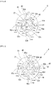
- Figure 3 shows a partial cross-sectional view of braking means in the drive control mechanism of the geared motor and a B-B line end view in the partial cross-sectional view.
- the drive control mechanism of the geared motor includes a geared motor formed by integrating an electric motor with a speed change unit including an input shaft that is a drive shaft of the electric motor, and braking means for controlling braking in each of driven and stopped states in an output shaft of the speed change unit, wherein the braking means includes a rotating part rotatably and pivotally supported by the drive shaft of the electric motor, and including a permanent magnet disposed in an annular shape, and a fixing part fixed to a case of the electric motor, and including a permanent magnet disposed facing the permanent magnet of the rotating part with a different polarity in the stopped state, and disposed in an annular shape.
- the drive control mechanism of a geared motor 1 includes an electric motor 2 that generates a rotational force required for driving a lifting operation in a lifting curtain 100; a speed change unit 3 including an input shaft 31 on one end side 21a of a drive shaft 21 in the electric motor 2 to decrease a speed of the rotational force, the speed change unit using this decelerated rotational force to generate, from an output shaft 32, a torque corresponding to the lifting operation of the lifting curtain 100; and braking means 4 disposed on another end side 21b of the drive shaft 21 in the electric motor 2, for controlling braking in each of driven and stopped states in the output shaft 32 of the speed change unit 3 by arranging one permanent magnet 43 rotatably and pivotally supported by the drive shaft 21 of the electric motor 2 and another permanent magnet 45 fixed to a case 20 of the electric motor 2 so that the permanent magnets face each other with different polarities in the stopped state of the electric motor.
- the braking means 4 may be provided between the electric motor 2 and the speed change unit 3.
- the braking means 4 includes a rotating part 40 rotatably and pivotally supported by the drive shaft 21 of the electric motor 2, and including the one permanent magnet 43 having a rectangular parallelepiped shape, and a fixing part 41 disposed on an outer side of the rotating part 40 offset to an electric motor 2 side to face a circumferential surface of the rotating part 40, fixed to the case 20 of the electric motor 2, and including the other permanent magnet 45 having a rectangular parallelepiped shape.
- the rotating part 40 consists of a disc-shaped body of a nonmagnetic material, and includes a storage part 42 including a plurality of cylindrical recesses arranged at equal intervals (each 90°) radially from a center of the disc-shaped body (drive shaft 21), and the one permanent magnet 43 (43a to 43d) having the rectangular parallelepiped shape and contained and fixed in the storage part 42.
- the one permanent magnet 43a to 43d is arranged so that polarities are aligned along a radial direction around the drive shaft 21, and all polarities adjacent to each other in a circumferential direction on a fixing part 41 side are the same polarity (e.g., N pole).
- the rotating part 40 has the center of the disc-shaped body pivotally supported by the drive shaft 21 of the electric motor 2, and is fixed rotatably with the rotation of the drive shaft 21.
- the fixing part 41 consists of a doughnut-shaped nonmagnetic material concentric with the rotating part 40 around the drive shaft 21, and includes a storage part 44 including a plurality of cylindrical recesses arranged at equal intervals (each 90°) radially from a center of the drive shaft, and the other permanent magnet 45 (45a to 45d) having the rectangular parallelepiped shape and contained and fixed in the storage part 44.
- the other permanent magnet 45a to 45d is arranged so that polarities are aligned along the radial direction around the drive shaft 21, and all polarities adjacent to each other in the circumferential direction on a rotating part 40 side are the same polarity and different (e.g., S pole) from those of the one permanent magnet 43a to 43d of the facing rotating part 40.
- the fixing part 41 is fixed to the case of the electric motor 2 on a one end face 20a side.
- the rotating part 40 and the fixing part 41 are always in a non-contact state via a gap regardless of an operation (driving or stopping) of the electric motor 2.
- an example shown in Figure 3 is an example where four permanent magnets 43a to 43d, 45a to 45d are arranged in each of the rotating part 40 and the fixing part 41, but three or another odd permanent magnets, or eight or another even permanent magnets may be arranged in each of the rotating part 40 and the fixing part 41, and the number of the magnets to be installed is not particularly limited. From the viewpoint of suppressing noise caused by vibration of the permanent magnets 43a to 43d, 45a to 45d due to attraction among the permanent magnets 43a to 43d and 45a to 45d in the rotating part 40 and the fixing part 41, magnetic forces of the individual permanent magnets 43a to 43d, 45a to 45d may be weakened and the number of the magnets to be installed may be increased. Therefore, as the permanent magnets 43a to 43d and 45a to 45d in the present embodiment, not only sintered magnets such as neodymium magnets but also plastic magnets and the like with a weaker magnetic force can be used.
- the number of the permanent magnets to be installed can be different between the rotating part 40 and the fixing part 41.
- four permanent magnets can be installed in the rotating part 40 and eight permanent magnets can be installed in the fixing part 41.
- the shape of the permanent magnets 43a to 43d, 45a to 45d a permanent magnet having a rectangular parallelepiped shape is shown, but if the polarity is opposite between the rotating part 40 and the fixing part 41 during the stopping operation, the shape is not particularly limited, and may be a rectangular column shape with a trapezoidal bottom surface, a spherical shape, or the like.
- a curtain lower end 103 is located at a top 100H of a drive range W, no current is supplied to the electric motor 2 in a stopped state, and the one permanent magnet 43a to 43d in the rotating part 40 of the braking means 4 is attracted by the magnetic field of the other permanent magnet 45a to 45d of the fixing part 41.
- the electric motor 2 is prevented from rotating and the lifting curtain 100 is maintained in the open state.
- a drive current is supplied from a power supply unit (not shown) to the electric motor 2.
- the supplying of this drive current starts rotation drive of the electric motor 2, generates an inertial force in a tangential direction in the rotating part 40 that rotates with the drive shaft 21 of the electric motor 2, releases an attracting state of the other permanent magnet 45a to 45d of the fixing part 41, and releases a braked state by the braking means 4.
- the releasing of the braked state by the braking means 4 brings the drive shaft 21 of the electric motor 2 into a free state, and the drive rotation of the electric motor 2 is inputted from the input shaft 31 via the drive shaft 21.
- the speed change unit 3 decelerates this inputted rotational force, and converts the force to a torque required for the lifting operation of the lifting curtain 100. By this converted rotational force, a lifting shaft 102 of the lifting curtain 100 is rotated to wind out a curtain 101 for shielding.
- the curtain lower end 103 can maintain the stopped state at the middle portion 100M, and the lifting curtain 100 can be in the semi-shielded state.
- the drive control unit 200 instructs that this semi-shielded state is shifted to a totally shielded state, the current supply from the power supply unit (not shown) to the electric motor 2 is started, and drive control is performed to a bottom 100L in the same manner as in a starting operation from the top 100H of the drive range W.
- the drive control mechanism of the geared motor 1 within a range where the relation among the drive torque F1, the drive torque F2 and the attraction force F3 is maintained can control any of the opening and shielding operations in the drive range W of the lifting curtain 100 only with on/off control of the supply current from the drive control unit 200 to the electric motor 2.
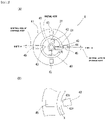
- FIG. 4 is an end view of braking means in the geared motor according to the present embodiment.
- one permanent magnet 53a to 53d is arranged in a storage part 42 so that polarities are aligned along a radial direction around a drive shaft 21, and polarities adjacent to each other in a circumferential direction on a fixing part 41 side that is an outer side in the radial direction alternately differ.
- another permanent magnet 55a to 55d is arranged in a storage part 44 so that polarities are aligned along the radial direction around the drive shaft 21, and polarities adjacent to each other in the circumferential direction on a rotating part 40 side that is an inner side in the radial direction alternately differ.
- a drive control force due to an attraction force between the polarity (e.g., N pole) of the one permanent magnet 53a of the rotating part 40 and the polarity of the other permanent magnet 55a of the fixing part 41 e.g., S pole
- the magnets being arranged to face each other during a stopping operation
- a drive control force due to a repulsion force between the N pole of the one permanent magnet 53a of the rotating part 40 and the N pole on the rotating part 40 side of the other permanent magnet 55b adjacent to the other permanent magnet 55a of the fixing part 41 enable smooth and reliable execution and maintenance of the stopping operation (here, a rotating direction of the drive shaft 21 is clockwise (rotating direction X)).
- a repulsion force between the N pole of the one permanent magnet 53a of the rotating part 40 and the N pole of the other permanent magnet 55a of the fixing part 41 can be used as a rotational force of the drive shaft, and the starting operation can be smoothly and reliably executed.
- the number of the permanent magnets to be arranged in the rotating part 40 and the fixing part 41 may be an odd number, and there may be a portion in which some of polarities adjacent to each other are the same polarity.
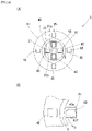
- FIG. 5 is an end view of braking means in the geared motor according to the present embodiment.
- One permanent magnet 63a to 63d of a rotating part 40 in braking means 6 has a square column shape with an isosceles trapezoidal bottom surface facing in a drive shaft 21 direction, and a surface 66 including an upper bottom and a surface 67 including a lower bottom are magnetic pole surfaces, respectively.
- the magnetic pole surfaces 66 and 67 are arranged in a storage part 62 to be aligned along a radial direction around the drive shaft 21.
- An area of the magnetic pole surface 66 including the upper bottom on a side facing another permanent magnet 65a to 65d of a fixing part 41 is smaller than an area of the magnetic pole surface 67 including the lower bottom on an opposite side (inner side in the radial direction).
- the other permanent magnet 65a to 65d of the fixing part 41 has a square column shape with an isosceles trapezoidal bottom surface facing in the drive shaft 21 direction, and a surface 68 including an upper bottom and a surface 69 including a lower bottom are magnetic pole surfaces, respectively.
- the magnetic pole surfaces 68 and 69 are arranged in a storage part 64 to be aligned along the radial direction around the drive shaft 21.
- An area of the magnetic pole surface 69 including the lower bottom on a side facing the one permanent magnet 63a to 63d of the rotating part 40 is smaller than an area of the magnetic pole surface 68 including the upper bottom on an opposite side (outer side in the radial direction).
- the shape of the permanent magnets 63a to 63d and 65a to 65d of the rotating part 40 and the fixing part 41 is not limited to the square column shape with the isosceles trapezoidal bottom surface, and may be any shape, if an area of the magnetic pole surface on a side where the permanent magnets 63a to 63d and 65a to 65d of the rotating part 40 and the fixing part 41 face each other is smaller than an area of the opposite magnetic pole surface, and a magnetic field of the magnetic pole surfaces facing each other becomes strong.
- a pulse magnetic field when magnetizing an unmagnetized magnet material as a molded body at a manufacturing stage of the permanent magnet, arrangement, strength or the like of a pulse magnetic field may be controlled, to increase a magnetic flux density in the magnetic field of the magnetic pole surface on the side where the permanent magnets of the rotating part 40 and the fixing part 41 face each other.
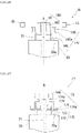
- FIG. 6 is a partial cross-sectional view of the geared motor in the drive control mechanism of the geared motor according to the present embodiment.
- Braking means 7 includes a rotating part 70 rotatably and pivotally supported by a drive shaft 21 of an electric motor 2, and including one permanent magnet 74 having a rectangular parallelepiped shape, and a fixing part 71 disposed inside offset to an electric motor 2 side of the rotating part 70 to face a circumferential surface of the rotating part 70 and fixed to a case 20 of the electric motor 2, and including another permanent magnet 76 having a rectangular parallelepiped shape.
- the rotating part 70 consists of a substantially disc-shaped body of a nonmagnetic material, and includes a storage part 73 including a plurality of cylindrical recesses arranged at equal intervals (each 90°) radially from a center of the disc-shaped body (drive shaft 21), and disposed on an outer side of a disc portion 72 offset to the electric motor 2 side, and the one permanent magnet 74 having the rectangular parallelepiped shape and contained and fixed in the storage part 73.
- the one permanent magnet 74 is disposed so that polarities are aligned along a radial direction around the drive shaft 21, and all polarities adjacent to each other in a circumferential direction on a fixing part 71 side are the same polarity (e.g., N pole).
- the fixing part 71 consists of a doughnut-shaped nonmagnetic material fixed to a protrusion 20b of the electric motor 2, and includes a storage part 75 including a plurality of cylindrical recesses arranged at equal intervals (each 90°) radially from a center of the doughnut shape (drive shaft 21), and the other permanent magnet 76 having a rectangular parallelepiped shape and contained and fixed in the storage part 75.
- the other permanent magnet 76 is disposed so that polarities are aligned along the radial direction around the drive shaft 21, and all polarities adjacent to each other in the circumferential direction on a rotating part 70 side are the same polarity and different (e.g., S pole) from the polarity of the one permanent magnet 74 of the facing rotating part 70.
- the drive control mechanism of the geared motor 1 similarly to the drive control mechanism of the geared motor 1 according to the above first embodiment, it is possible to decelerate a rotation output of the electric motor 2 by a speed change unit 3 and output a driving force of the geared motor 1, execute a stopping operation between a start point and an end point in a drive range by this driving force, maintain this stopping operation, and smoothly and reliably execute respective operations that start from this stopped state without applying any external force other than a drive input of the electric motor 2.
- FIG. 7 shows an end view of braking means in the geared motor according to the present embodiment, and an operation mode diagram.
- Braking means 8 includes a common configuration in which one permanent magnet 43 is contained in each storage part 81 of a rotating part 40, and a fixing part 41 including another permanent magnet 45 is disposed in a circle concentric with the rotating part 40, and a central axis (plane arrangement) of the one permanent magnet 43 and each storage part 81 is shifted by a very small amount ⁇ from a radial axis around a drive shaft 21 of an electric motor 2.
- FIG. 8 shows an end view of braking means in the geared motor according to the present embodiment, and an operation mode diagram.
- Braking means 9 includes a common configuration where one permanent magnet 43 is slidably contained in each storage part 91 of a rotating part 40, and a fixing part 41 including another permanent magnet 45 is disposed in a circle concentric with the rotating part 40, and each storage part 91 of the rotating part 40 has gaps 91a and 91b formed from left and right surfaces of the one permanent magnet 43 in a radial direction.
- the one permanent magnet 43 in each storage part 91 tilts (falls) in a falling direction Y depending on a rotating direction X of a drive shaft 21 driven by an electric motor 2. Therefore, a magnetic flux distribution between a front end 43e and a rear end 43f of the one permanent magnet 43, and the other permanent magnet 45 can be biased to a front end 43e side of the one permanent magnet 43 which is a tip side in the rotating direction X, so that it is possible to smoothly and reliably shift from a stopped state to a starting state.
- a protrusion may be provided on a surface opposite to the fixing part 41 of the storage part 91 on which the one permanent magnet 43 abuts, and the one permanent magnet 43 may be tilted starting from the protrusion.
- each storage part 91 has a substantially rectangular parallelepiped shape, and if at least a part of a surface opposite to the fixing part 41 is tapered or curved, the tilt of the one permanent magnet 43 can be more effectively promoted.
- FIG. 9 is an end view of braking means in the geared motor according to the present embodiment.
- one permanent magnet 203a to 203f is arranged in a storage part 42 so that polarities are aligned along a radial direction around a drive shaft 21, and all polarities adjacent to each other in a circumferential direction on a fixing part 41 side are the same polarity (e.g., N pole).
- another permanent magnet 205a to 205f is arranged in a storage part 44 so that polarities are aligned along the radial direction around the drive shaft 21, a magnetic pole on a rotating part 40 side has the same polarity as that of the one permanent magnet 203a to 203f of the rotating part 40 facing the fixing part, and all polarities adjacent to each other in the circumferential direction on the rotating part 40 side that is an inner side in the radial direction are the same polarity (e.g., N pole).
- the one permanent magnet 203a to 203f of the rotating part 40 stops at a position where a repulsion force received from a magnetic field produced by the other permanent magnet 205a to 205f of the facing fixing part 41 is balanced.
- the one permanent magnet 203a of the rotating part 40 stops at a middle position in the circumferential direction between the other permanent magnet 205a and the other permanent magnet 205b in the fixing part 41.
- the one permanent magnet 203a to 203f of the rotating part 40 is stopped at the position where the repulsion force received from the magnetic field produced by the other permanent magnet 205a to 205f of the fixing part 41 is balanced, that is, less influence is received from the magnetic field of the other permanent magnet 205a to 205f, so that a starting operation of the geared motor 1 can be smoothly executed.
- the number of the magnetic poles of the permanent magnet in each of the rotating part 40 and the fixing part 41 is six has been described, but this case is not limited.
- more permanent magnets may be installed to perform the stopping operation of the geared motor 1 more smoothly and reliably, and the number of the permanent magnets to be installed is appropriately set in consideration of strength of the magnetic field of the permanent magnet, smooth execution of starting and stopping, and the like.
- the rotating part is pivotably supported at a fixed position of the drive shaft, but, the rotating part may have a slide function so that the rotating part can slide along the drive shaft in a direction away from the other permanent magnet of the fixing part when the geared motor is in a starting state.
- the rotating part moves away from the fixing part with the rotation of the drive shaft, an area of the facing (overlapping) magnetic pole surface between one permanent magnet of the rotating part and the other permanent magnet of the fixing part gradually decreases, that is, an attraction force acting between the rotating part and the fixing part is reduced, thereby allowing the drive shaft to smoothly rotate at an earlier stage.
- one permanent magnet of the rotating part may be used also as a permanent magnet for the magnetic encoder.
- the magnetic pole surface is extended along a drive shaft direction from the magnetic pole surface of the other permanent magnet of the fixing part, and an extended magnetic pole surface portion is disposed to face Hall element.
- FIG. 10 is a partial cross-sectional view of the geared motor in the drive control mechanism of the geared motor
- Figure 11 shows a partial cross-sectional view of braking means in the drive control mechanism of the geared motor and a C-C line end view in the partial cross-sectional view.
- the drive control mechanism of the geared motor includes the geared motor formed by integrating an electric motor with a speed change unit including an input shaft that is a drive shaft of the electric motor, and braking means for controlling braking in each of driven and stopped states in an output shaft of the speed change unit, and the braking means includes a rotating part rotatably and pivotally supported by the drive shaft of the electric motor, and including a permanent magnet disposed in an annular shape, and a fixing part fixed to a case of the electric motor, and including a permanent magnet disposed facing the permanent magnet of the rotating part with a different polarity in the stopped state, and disposed in an annular shape.
- the drive control mechanism of a geared motor 1 includes an electric motor 2 that generates a rotational force required for driving a lifting operation in a lifting curtain 100; a speed change unit 3 including an input shaft 31 that is one end side 21a of a drive shaft 21 in the electric motor 2 to decelerate the rotational force, and generates a torque corresponding to the lifting operation of the lifting curtain 100 from an output shaft 32 with the decelerated rotational force; and braking means 14 disposed on the other end side 21b of the drive shaft 21 in the electric motor 2, and controlling braking in the output shaft 32 of the speed change unit 3 by arranging a radially oriented permanent magnet 143 rotatably and pivotally supported by the drive shaft 21 of the electric motor 2 and a radially oriented permanent magnet 146 fixed to a case 20 of the electric motor 2 so that the radially oriented permanent magnets face each other.
- the braking means 14 can drive and control the drive shaft 21 of a small torque output with high-speed rotation from the electric motor 2, so that it is possible to smoothly and reliably execute respective operations of starting and stopping and maintaining a stopped state with a machine configuration that is as simple as possible.
- the braking means 14 may be provided between the electric motor 2 and the speed change unit 3.
- the braking means 14 includes a rotating part 140 formed of an annular body rotatably and pivotally supported by the drive shaft 21 of the electric motor 2, and including the radially oriented permanent magnet 143 (143a to 143d) divided into a plurality of portions in a circumferential direction of the annular body, each of the respective divided portions being magnetized in a radial direction, respective adjacent portions having different polarities from each other; and a fixing part 141 formed of an annular body disposed facing a circumferential surface of the rotating part 140 and fixed to the case 20 of the electric motor 2, and including the radially oriented permanent magnet 146 (146a to 146d) divided into a plurality of portions in a circumferential direction of the annular body, each of the respective divided portions being magnetized in a radial direction, respective adjacent portions having different polarities from each other.
- a rotating part 140 formed of an annular body rotatably and pivotally supported by the drive shaft 21 of the electric motor 2, and including the radially oriented permanent magnet
- the rotating part 140 includes a holding part 142 including a recess 142b formed at one end of a base, and a brim portion 142a formed on an intermediate outer periphery of a side surface of the base, the recess 142b being pivotally supported by the drive shaft 21 around an axis A of the electric motor 2 and rotating with drive of the drive shaft 21; the radially oriented permanent magnet 143 (143a to 143d) disposed in an annular shape fixed to an electric motor 2 side of the holding part 142; and a permanent magnet 144 for a magnetic encoder, disposed facing the radially oriented permanent magnet 143a to 143d via the brim portion 142a of the holding part 142.
- the brim portion 142a holds an interval between the radially oriented permanent magnet 143a to 143d and the permanent magnet 144 that are arranged on opposite end sides in the base of the holding part 142 to prevent mutual interference of magnetic fields.
- the permanent magnet 144 for the magnetic encoder detects a rotational speed or the like of the electric motor 2 with Hall element 15 disposed on a substrate (not shown) to which the geared motor 1 is fixed.
- the fixing part 141 includes a storage part 145 fixed to the case 20 of the electric motor 2 on a one end face 20a side, and including a stepped portion 145a having a diameter increasing toward a side opposite to the electric motor 2, and the annular radially oriented permanent magnet 146 (146a to 146d) fixed to the stepped portion 145a, and disposed outside and facing, via an interval, the radially oriented permanent magnet 143a to 143d of the rotating part 140.
- Figure 12 is a schematic view showing an example of the radially oriented permanent magnet according to the present embodiment
- Figure 13 is a schematic view showing another example of the radially oriented permanent magnet.
- the radially oriented permanent magnets 143 and 146 are inner and outer circumference multipole magnets in each of which a plurality of S and N poles are alternately magnetized along a circumferential direction at an inner circumferential edge and an outer circumferential edge, and different magnetic poles are magnetized in a radial direction.
- different magnetic poles of the radially oriented permanent magnets 143 and 146 of the rotating part 140 and the fixing part 141 face each other.
- the inner and outer circumference multipole magnet consists of the even number of the poles
- the magnetic poles between the adjacent magnets can be different, and the drive control force can be controlled more strongly by applying both the attraction force and the repulsion force of the magnetic poles, and a plurality of annular magnets can be stably and firmly arranged.
- the radially oriented permanent magnet 143 of the rotating part 140 preferably has the magnetic field due to the magnetic pole (outside) facing the fixing part 141 that is stronger than the magnetic field due to the opposite magnetic pole (inside).
- the radially oriented permanent magnet 146 of the fixing part 141 preferably has the magnetic field due to the magnetic pole (inside) facing the rotating part 140 that is stronger than the magnetic field due to the opposite magnetic pole (outside).
- the magnetic field is formed between different magnetic poles adjacent to each other in the circumferential direction. Therefore, if the magnetic field formed on the side where the radially oriented permanent magnets 143 and 146 of the rotating part 140 and the fixing part 141 face each other is strengthened, the magnetic force acting between the rotating part 140 and the fixing part 141 can be increased, enabling execution and maintenance of the stopping operation smoothly and reliably.
- the strength of the magnetic field of the inner and outer circumference multipole magnet can be adjusted by controlling arrangement, strength or the like of a pulse magnetic field when magnetizing an unmagnetized magnet material as a molded body at a manufacturing stage of the permanent magnet.
- the radially oriented permanent magnets 143 and 146 of the present embodiment not only sintered magnets such as neodymium magnets but also plastic magnets having weaker magnetic force can be used.
- a curtain lower end 103 is located at a top 100H of a drive range W, no current is supplied to the electric motor 2 in a stopped state, and the radially oriented permanent magnet 143a to 143d in the rotating part 140 of the braking means 14 is attracted by the magnetic field of the radially oriented permanent magnet 146a to 146d of the fixing part 141.
- the electric motor 2 is prevented from rotating and the lifting curtain 100 is maintained in the open state.
- a drive current is supplied from a power supply unit (not shown) to the electric motor 2.
- the supplying of this drive current starts rotation drive of the electric motor 2, generates a centrifugal force at the rotating part 140 that rotates with the drive shaft 21 of the electric motor 2, releases the rotating part from an attracting state of the radially oriented permanent magnet 146a to 146d of the fixing part 141, and releases a braked state by the braking means 14.
- the releasing of the braked state by the braking means 14 brings the drive shaft 21 of the electric motor 2 into a free state, and the drive rotation of the electric motor 2 is inputted from the input shaft 31 via the drive shaft 21.
- the speed change unit 3 decelerates the inputted rotational force, and converts the force to a torque required for the lifting operation of the lifting curtain 100. By this converted rotational force, a lifting shaft 102 of the lifting curtain 100 is rotated to wind out a curtain 101 for shielding.
- the curtain lower end 103 can maintain the stopped state at the middle portion 100M, and the lifting curtain 100 can be in the semi-shielded state.
- the drive control unit 200 instructs that this semi-shielded state is shifted to a totally shielded state, the current supply from the power supply unit (not shown) to the electric motor 2 is started, and drive control is performed to a bottom 100L in the same manner as in a starting operation from the top 100H of the drive range W.
- the drive control mechanism of the geared motor 1 within a range where the relation among the drive torque F1, the drive torque F2 and the attraction force F3 is maintained can control any of the opening and shielding operations in the drive range W of the lifting curtain 100 only with on/off control of the supply current from the drive control unit 200 to the electric motor 2.
- Figure 14 is a partial cross-sectional view of the geared motor in the drive control mechanism of the geared motor according to the present embodiment.
- braking means 16 includes a rotating part 160 formed of an annular body rotatably and pivotally supported by a drive shaft 21 of an electric motor 2, and including a radially oriented permanent magnet 162 divided into a plurality of portions in a circumferential direction of the annular body, each divided portion being magnetized in a radial direction with different polarities of respective adjacent portions; and a fixing part 141 formed of an annular body disposed on an outer side of the rotating part 160 offset to an electric motor 2 side to face a circumferential surface of the rotating part 160, and fixed to a case 20 of the electric motor 2, and including an annular radially oriented permanent magnet 146 divided into a plurality of portions in a circumferential direction of the annular body, each divided portion being magnetized in the radial direction with different polarities of respective adjacent portions.
- the rotating part 160 includes a holding part 161 that is pivotally supported by the drive shaft 21 around an axis A and rotates with drive of the drive shaft 21, and the radially oriented permanent magnet 162 disposed in an annular shape fixed to an outer circumferential surface of the holding part 161, and formed with a longer dimension than the radially oriented permanent magnet 146.
- the radially oriented permanent magnet 162 is provided so that a magnetic pole surface facing the radially oriented permanent magnet 146 of the fixing part 141 extends along the drive shaft 21 in an opposite direction to the electric motor 2.
- This extended portion functions as a permanent magnet for a magnetic encoder, and detects a rotational speed or the like of the electric motor 2 with Hall element 15.
- the permanent magnet for the magnetic encoder is unnecessary, and the number of members of the braking means 16 can be reduced compared to the braking means 14 according to the above eighth embodiment, and the configuration is simplified to be easier to assemble.
- Figure 15 is a partial cross-sectional view of the geared motor in the drive control mechanism of the geared motor according to the present embodiment.
- braking means 17 includes a fixing part 170 formed of an annular body fixed to a case 20 of an electric motor 2, and including a radially oriented permanent magnet 173 divided into a plurality of portions in a circumferential direction of the annular body, each divided portion being magnetized in a radial direction with different polarities of respective adjacent portions; and a rotating part 171 formed of an annular body disposed on an outer side of the fixing part 170 to face an outer circumferential surface of the fixing part 170, and rotatably and pivotally supported by a drive shaft 21 of the electric motor 2, and including a radially oriented permanent magnet 175 divided into a plurality of portions in a circumferential direction of the annular body, each divided portion being magnetized in the radial direction with different polarities of respective adjacent portions.
- the fixing part 170 includes a storage part 172 fixed to the case 20 of the electric motor 2 on a one end face 20a side, and the annular radially oriented permanent magnet 173 disposed in the storage part 172 around an axis A.
- the rotating part 171 includes a holding part 174 that is pivotally supported by the drive shaft 21 around the axis A and rotates with drive of the drive shaft 21; the radially oriented permanent magnet 175 fixed to a mounting portion 174a of the holding part 174 and disposed in an annular shape; and a permanent magnet 144 for a magnetic encoder that is disposed on a side opposite to the electric motor 2 via a brim portion 174b of the holding part 174 and fixed to the brim portion 174b.
- the mounting portion 174a is formed at an interval from the fixing part 170 so that the radially oriented permanent magnet 175 of the rotating part 171 is disposed outside and facing the radially oriented permanent magnet 173 of the fixing part 170, as seen from an axial direction of the geared motor 1.
- the drive control mechanism of the geared motor 1 in the same manner as in the drive control mechanism of the geared motor 1 according to the above eighth embodiment, it is possible to decelerate a rotation output of the electric motor 2 by the speed change unit 3 and output a driving force of the geared motor 1, execute a stopping operation between a start point and an end point in a drive range by this driving force, maintain this stopping operation, and smoothly and reliably execute respective operations that start from this stopped state without applying any external force other than a drive input of the electric motor.
- the radially oriented permanent magnet 175 of the rotating part 171 since the radially oriented permanent magnet 175 of the rotating part 171 is disposed on the outermost side, the radially oriented permanent magnet 175 may be used also as a permanent magnet for a magnetic encoder by disposing Hall element 15 outside at an interval from the radially oriented permanent magnet 175, instead of providing the permanent magnet 144 for the magnetic encoder in the rotating part 171.
- the rotating part is pivotally supported at a fixed position of the drive shaft, but the rotating part may be provided with a slide function so that the rotating part can slide along the drive shaft in a direction away from the radially oriented permanent magnet of the fixing part when the geared motor is in a starting state.
- the rotating part moves away from the fixing part with the rotation of the drive shaft, an area where the radially oriented permanent magnet of the rotating part and the radially oriented permanent magnet of the fixing part face each other gradually decreases, that is, the magnetic force acting between the rotating part and the fixing part is reduced, thereby allowing the drive shaft to smoothly rotate at an earlier stage.
Landscapes
- Engineering & Computer Science (AREA)
- Structural Engineering (AREA)
- Power Engineering (AREA)
- Architecture (AREA)
- Civil Engineering (AREA)
- General Engineering & Computer Science (AREA)
- Physics & Mathematics (AREA)
- Electromagnetism (AREA)
- Mechanical Engineering (AREA)
- Connection Of Motors, Electrical Generators, Mechanical Devices, And The Like (AREA)
- Dynamo-Electric Clutches, Dynamo-Electric Brakes (AREA)
- Braking Arrangements (AREA)
Applications Claiming Priority (2)
| Application Number | Priority Date | Filing Date | Title |
|---|---|---|---|
| JP2019211173A JP7493216B2 (ja) | 2019-11-22 | 2019-11-22 | ギヤードモータの駆動制御機構 |
| PCT/JP2020/043501 WO2021100871A1 (fr) | 2019-11-22 | 2020-11-20 | Mécanisme de commande d'entraînement de moteur à engrenages |
Publications (2)
| Publication Number | Publication Date |
|---|---|
| EP4064535A1 true EP4064535A1 (fr) | 2022-09-28 |
| EP4064535A4 EP4064535A4 (fr) | 2023-11-29 |
Family
ID=75963413
Family Applications (1)
| Application Number | Title | Priority Date | Filing Date |
|---|---|---|---|
| EP20891061.2A Pending EP4064535A4 (fr) | 2019-11-22 | 2020-11-20 | Mécanisme de commande d'entraînement de moteur à engrenages |
Country Status (6)
| Country | Link |
|---|---|
| US (2) | US12316195B2 (fr) |
| EP (1) | EP4064535A4 (fr) |
| JP (2) | JP7493216B2 (fr) |
| CN (1) | CN114788151A (fr) |
| PH (1) | PH12022551198A1 (fr) |
| WO (1) | WO2021100871A1 (fr) |
Cited By (1)
| Publication number | Priority date | Publication date | Assignee | Title |
|---|---|---|---|---|
| FR3159717A1 (fr) * | 2024-02-28 | 2025-08-29 | Bontaz Centre | Dispositif de blocage magnétique et de mesure de position pour un organe rotatif |
Families Citing this family (1)
| Publication number | Priority date | Publication date | Assignee | Title |
|---|---|---|---|---|
| CN116242406B (zh) * | 2023-03-02 | 2023-09-19 | 苏州倍斯维尔自动化科技有限公司 | 一种物流仓储巡检机器人 |
Family Cites Families (40)
| Publication number | Priority date | Publication date | Assignee | Title |
|---|---|---|---|---|
| JPS61154475A (ja) * | 1984-12-26 | 1986-07-14 | Japan Servo Co Ltd | 制動装置を内蔵した小形電動機 |
| JPS61153467A (ja) | 1984-12-27 | 1986-07-12 | 松下冷機株式会社 | 気液分離器 |
| JPH0811035Y2 (ja) | 1990-10-01 | 1996-03-29 | 株式会社安川電機 | サーボアクチュエータ |
| JPH07111772A (ja) | 1993-10-07 | 1995-04-25 | Koyo Seiko Co Ltd | 磁気継手 |
| JPH07194092A (ja) | 1993-12-24 | 1995-07-28 | Minoru Kobayashi | 永久磁石使用型回転力伝動装置およびブラインド内蔵型複層ガラス |
| US5751127A (en) * | 1995-07-06 | 1998-05-12 | Grimes Aerospace Company | Magnet brake |
| JPH0974777A (ja) | 1995-09-08 | 1997-03-18 | Nippon Soken Inc | 磁気カップリング装置 |
| JPH10243628A (ja) * | 1997-02-27 | 1998-09-11 | Akebono Brake Res & Dev Center Ltd | 電磁力ブレーキ装置 |
| JPH11153186A (ja) * | 1997-11-18 | 1999-06-08 | Fuji Seiki Co Ltd | 回転動作支持機構及びロータリーダンパ |
| JP2001136718A (ja) | 1999-11-08 | 2001-05-18 | Shibaura Densan Kk | 電動機 |
| JP2003004074A (ja) | 2001-06-20 | 2003-01-08 | Fuji Hensokuki Co Ltd | 電磁ブレーキ及び電磁ブレーキ付き駆動装置 |
| JP2004048963A (ja) | 2002-07-15 | 2004-02-12 | Sumitomo Metal Ind Ltd | 渦電流式減速装置及びそれに用いる永久磁石 |
| KR100437058B1 (ko) | 2002-10-01 | 2004-06-23 | 엘지전자 주식회사 | 단상 모터 |
| FR2851092A1 (fr) * | 2003-02-11 | 2004-08-13 | Rene Yhannis Elitchay | Moteur magnetique, utilisant les champs magnetiques crees par des aimants sans apport d'energie exterieure continue |
| US6794778B1 (en) | 2003-05-23 | 2004-09-21 | Harmonic Design, Inc. | Braking system for powered window covering |
| JP2005269709A (ja) * | 2004-03-16 | 2005-09-29 | Maguneo Giken:Kk | 磁気回転伝達装置及び密閉撹拌装置 |
| JP4577604B2 (ja) | 2004-04-30 | 2010-11-10 | ミネベア株式会社 | 異方性希土類ボンド磁石の製造方法 |
| JP4478869B2 (ja) | 2004-05-06 | 2010-06-09 | ミネベア株式会社 | 異方性ボンド磁石の製造方法 |
| JP4533001B2 (ja) | 2004-06-04 | 2010-08-25 | 長谷川 仁 | 暖簾装置 |
| FR2884269B1 (fr) | 2005-04-12 | 2007-06-15 | Radio Electr Et Mecanique Sire | Tambour d'enroulement/deroulement pour un rideau flottant de couverture de piscine |
| JP4781761B2 (ja) | 2005-09-15 | 2011-09-28 | 三和シヤッター工業株式会社 | 自動復帰型自動閉鎖装置 |
| JP2007194092A (ja) | 2006-01-19 | 2007-08-02 | Fujikura Ltd | メンブレンシート及びスイッチ装置 |
| JP4798543B2 (ja) * | 2006-03-16 | 2011-10-19 | 株式会社安川電機 | ブレーキ付モータとこれを備えたロボット装置 |
| JP2008092754A (ja) | 2006-10-05 | 2008-04-17 | Mitsuba Corp | 電動モータの休止時回転防止構造 |
| WO2008085931A2 (fr) * | 2007-01-09 | 2008-07-17 | Magnetic Torque International, Ltd. | Système d'engrenages planétaires magnétique et dispositif l'utilisant |
| ES2316274B1 (es) | 2007-03-08 | 2010-02-01 | Jecsalis Dissenys I Patents, S.L. | Dispositivo motor por interaccion selectiva de campos magneticos. |
| FR2929771B1 (fr) | 2008-04-07 | 2013-02-15 | Unicum Transmission De Puissance | Dispositif de freinage magnetique et d'arret en rotation d'axes motorises. |
| JP2010024752A (ja) | 2008-07-22 | 2010-02-04 | Tostem Corp | シャッター装置 |
| JP5291487B2 (ja) | 2009-02-18 | 2013-09-18 | 文化シヤッター株式会社 | シャッター装置のシャッターカーテン急速異常降下防止装置及びその方法 |
| JP2010243628A (ja) | 2009-04-02 | 2010-10-28 | Seiko Epson Corp | 画像形成装置の制御方法、画像形成装置 |
| FR2948724B1 (fr) | 2009-07-30 | 2017-10-27 | Maviflex | Dispositif de transmission antichute pour porte de manutention a rideau souple |
| JP2011144854A (ja) | 2010-01-13 | 2011-07-28 | Yaskawa Electric Corp | 無励磁作動ブレーキおよびブレーキ内蔵型ギヤードモータ |
| JP5397409B2 (ja) * | 2011-05-13 | 2014-01-22 | 株式会社安川電機 | モータ |
| JP2016054669A (ja) * | 2014-09-08 | 2016-04-21 | 中国電力株式会社 | 鳥害防止具 |
| FR3035279A1 (fr) | 2015-04-17 | 2016-10-21 | Moteurs Leroy-Somer | Frein magnetique pour machine electrique |
| WO2017015764A1 (fr) * | 2015-07-29 | 2017-02-02 | Hydro-Quebec | Mécanisme statiquement équilibré à l'aide de cylindres de halbach |
| FR3065594B1 (fr) * | 2017-04-25 | 2019-06-14 | Unicum Transmission De Puissance | Motoreducteur a freinage magnetique |
| CN109217630A (zh) * | 2018-11-13 | 2019-01-15 | 煤科集团沈阳研究院有限公司 | 一种矿用筒式同步型永磁传动装置 |
| EP3706292A1 (fr) | 2019-03-04 | 2020-09-09 | VKR Holding A/S | Système d'entraînement électrique pour déplacer un élément de construction doté d'un frein magnétique |
| JP7751976B2 (ja) | 2021-02-26 | 2025-10-09 | ミネベアミツミ株式会社 | モータ |
-
2019
- 2019-11-22 JP JP2019211173A patent/JP7493216B2/ja active Active
-
2020
- 2020-11-20 PH PH1/2022/551198A patent/PH12022551198A1/en unknown
- 2020-11-20 US US17/778,305 patent/US12316195B2/en active Active
- 2020-11-20 EP EP20891061.2A patent/EP4064535A4/fr active Pending
- 2020-11-20 CN CN202080080214.8A patent/CN114788151A/zh active Pending
- 2020-11-20 WO PCT/JP2020/043501 patent/WO2021100871A1/fr not_active Ceased
-
2024
- 2024-01-16 JP JP2024004875A patent/JP7659854B2/ja active Active
-
2025
- 2025-04-17 US US19/181,352 patent/US20250337298A1/en active Pending
Cited By (1)
| Publication number | Priority date | Publication date | Assignee | Title |
|---|---|---|---|---|
| FR3159717A1 (fr) * | 2024-02-28 | 2025-08-29 | Bontaz Centre | Dispositif de blocage magnétique et de mesure de position pour un organe rotatif |
Also Published As
| Publication number | Publication date |
|---|---|
| US20250337298A1 (en) | 2025-10-30 |
| EP4064535A4 (fr) | 2023-11-29 |
| US20230006509A1 (en) | 2023-01-05 |
| JP2021083272A (ja) | 2021-05-27 |
| JP7659854B2 (ja) | 2025-04-10 |
| JP7493216B2 (ja) | 2024-05-31 |
| CN114788151A (zh) | 2022-07-22 |
| PH12022551198A1 (en) | 2023-09-25 |
| US12316195B2 (en) | 2025-05-27 |
| JP2024041940A (ja) | 2024-03-27 |
| WO2021100871A1 (fr) | 2021-05-27 |
Similar Documents
| Publication | Publication Date | Title |
|---|---|---|
| US20250337298A1 (en) | Geared motor drive control mechanism | |
| EP3818917B1 (fr) | Coupleur magnétique sans contact pour un appareil de traitement d'aliments équipé d'un petit moteur à aimant permanent sans balais | |
| EP2110933B1 (fr) | Moteur, structure de rotor et machine magnétique | |
| US5751127A (en) | Magnet brake | |
| US4837470A (en) | Magnetically driven nutating motor | |
| EP1729403B1 (fr) | Dispositif d'entraînement | |
| JP4378326B2 (ja) | 駆動装置及び光量調節装置 | |
| US11731263B2 (en) | Brake apparatus, robot joint and robot including the same | |
| JP7345161B2 (ja) | ギヤードモータの駆動制御機構 | |
| EP3706292A1 (fr) | Système d'entraînement électrique pour déplacer un élément de construction doté d'un frein magnétique | |
| HK40078149A (en) | Geared motor drive control mechanism | |
| US20230026553A1 (en) | Stator and rotary electric machine using same | |
| JP6616538B1 (ja) | 回転装置及び発電システム | |
| JP7308510B2 (ja) | ギヤードモータの駆動制御機構 | |
| JP2005233326A (ja) | 伝達機構 | |
| JP3234309U (ja) | モータとサイクロイド減速機からなる駆動装置 | |
| KR100301517B1 (ko) | 비엘디시 모터의 회전자구조 | |
| JP2006097738A (ja) | 電磁クラッチ | |
| JPH0140353Y2 (fr) | ||
| JP6014017B2 (ja) | ブレーキ付モータ | |
| CN116802972A (zh) | 旋转机 | |
| KR20100070312A (ko) | 모터 | |
| JPH05300724A (ja) | 電磁ブレーキ | |
| JPS5811037B2 (ja) | 制御棒駆動装置 | |
| JP2001251844A (ja) | 回転伝動装置 |
Legal Events
| Date | Code | Title | Description |
|---|---|---|---|
| STAA | Information on the status of an ep patent application or granted ep patent |
Free format text: STATUS: THE INTERNATIONAL PUBLICATION HAS BEEN MADE |
|
| PUAI | Public reference made under article 153(3) epc to a published international application that has entered the european phase |
Free format text: ORIGINAL CODE: 0009012 |
|
| STAA | Information on the status of an ep patent application or granted ep patent |
Free format text: STATUS: REQUEST FOR EXAMINATION WAS MADE |
|
| 17P | Request for examination filed |
Effective date: 20220516 |
|
| AK | Designated contracting states |
Kind code of ref document: A1 Designated state(s): AL AT BE BG CH CY CZ DE DK EE ES FI FR GB GR HR HU IE IS IT LI LT LU LV MC MK MT NL NO PL PT RO RS SE SI SK SM TR |
|
| DAV | Request for validation of the european patent (deleted) | ||
| DAX | Request for extension of the european patent (deleted) | ||
| A4 | Supplementary search report drawn up and despatched |
Effective date: 20231027 |
|
| RIC1 | Information provided on ipc code assigned before grant |
Ipc: F16D 49/00 20060101ALI20231023BHEP Ipc: E06B 9/84 20060101ALI20231023BHEP Ipc: A47H 5/02 20060101ALI20231023BHEP Ipc: H02K 7/106 20060101ALI20231023BHEP Ipc: H02K 7/116 20060101ALI20231023BHEP Ipc: H02K 7/102 20060101ALI20231023BHEP Ipc: H02K 49/10 20060101AFI20231023BHEP |
|
| TPAC | Observations filed by third parties |
Free format text: ORIGINAL CODE: EPIDOSNTIPA |