EP4064546A1 - Convertisseur et procédé de fonctionnement du convertisseur - Google Patents
Convertisseur et procédé de fonctionnement du convertisseur Download PDFInfo
- Publication number
- EP4064546A1 EP4064546A1 EP21164446.3A EP21164446A EP4064546A1 EP 4064546 A1 EP4064546 A1 EP 4064546A1 EP 21164446 A EP21164446 A EP 21164446A EP 4064546 A1 EP4064546 A1 EP 4064546A1
- Authority
- EP
- European Patent Office
- Prior art keywords
- converter
- temperature
- temperature values
- service life
- power converter
- Prior art date
- Legal status (The legal status is an assumption and is not a legal conclusion. Google has not performed a legal analysis and makes no representation as to the accuracy of the status listed.)
- Granted
Links
Images
Classifications
-
- H—ELECTRICITY
- H02—GENERATION; CONVERSION OR DISTRIBUTION OF ELECTRIC POWER
- H02M—APPARATUS FOR CONVERSION BETWEEN AC AND AC, BETWEEN AC AND DC, OR BETWEEN DC AND DC, AND FOR USE WITH MAINS OR SIMILAR POWER SUPPLY SYSTEMS; CONVERSION OF DC OR AC INPUT POWER INTO SURGE OUTPUT POWER; CONTROL OR REGULATION THEREOF
- H02M7/00—Conversion of AC power input into DC power output; Conversion of DC power input into AC power output
- H02M7/42—Conversion of DC power input into AC power output without possibility of reversal
- H02M7/44—Conversion of DC power input into AC power output without possibility of reversal by static converters
- H02M7/48—Conversion of DC power input into AC power output without possibility of reversal by static converters using discharge tubes with control electrode or semiconductor devices with control electrode
- H02M7/483—Converters with outputs that each can have more than two voltages levels
- H02M7/4835—Converters with outputs that each can have more than two voltages levels comprising two or more cells, each including a switchable capacitor, the capacitors having a nominal charge voltage which corresponds to a given fraction of the input voltage, and the capacitors being selectively connected in series to determine the instantaneous output voltage
-
- H—ELECTRICITY
- H02—GENERATION; CONVERSION OR DISTRIBUTION OF ELECTRIC POWER
- H02M—APPARATUS FOR CONVERSION BETWEEN AC AND AC, BETWEEN AC AND DC, OR BETWEEN DC AND DC, AND FOR USE WITH MAINS OR SIMILAR POWER SUPPLY SYSTEMS; CONVERSION OF DC OR AC INPUT POWER INTO SURGE OUTPUT POWER; CONTROL OR REGULATION THEREOF
- H02M1/00—Details of apparatus for conversion
- H02M1/32—Means for protecting converters other than automatic disconnection
-
- G—PHYSICS
- G01—MEASURING; TESTING
- G01K—MEASURING TEMPERATURE; MEASURING QUANTITY OF HEAT; THERMALLY-SENSITIVE ELEMENTS NOT OTHERWISE PROVIDED FOR
- G01K3/00—Thermometers giving results other than momentary value of temperature
- G01K3/08—Thermometers giving results other than momentary value of temperature giving differences of values; giving differentiated values
- G01K3/10—Thermometers giving results other than momentary value of temperature giving differences of values; giving differentiated values in respect of time, e.g. reacting only to a quick change of temperature
-
- H—ELECTRICITY
- H02—GENERATION; CONVERSION OR DISTRIBUTION OF ELECTRIC POWER
- H02M—APPARATUS FOR CONVERSION BETWEEN AC AND AC, BETWEEN AC AND DC, OR BETWEEN DC AND DC, AND FOR USE WITH MAINS OR SIMILAR POWER SUPPLY SYSTEMS; CONVERSION OF DC OR AC INPUT POWER INTO SURGE OUTPUT POWER; CONTROL OR REGULATION THEREOF
- H02M1/00—Details of apparatus for conversion
- H02M1/0003—Details of control, feedback or regulation circuits
- H02M1/0012—Control circuits using digital or numerical techniques
-
- H—ELECTRICITY
- H02—GENERATION; CONVERSION OR DISTRIBUTION OF ELECTRIC POWER
- H02M—APPARATUS FOR CONVERSION BETWEEN AC AND AC, BETWEEN AC AND DC, OR BETWEEN DC AND DC, AND FOR USE WITH MAINS OR SIMILAR POWER SUPPLY SYSTEMS; CONVERSION OF DC OR AC INPUT POWER INTO SURGE OUTPUT POWER; CONTROL OR REGULATION THEREOF
- H02M1/00—Details of apparatus for conversion
- H02M1/10—Arrangements incorporating converting means for enabling loads to be operated at will from different kinds of power supplies, e.g. from AC or DC
-
- G—PHYSICS
- G01—MEASURING; TESTING
- G01R—MEASURING ELECTRIC VARIABLES; MEASURING MAGNETIC VARIABLES
- G01R31/00—Arrangements for testing electric properties; Arrangements for locating electric faults; Arrangements for electrical testing characterised by what is being tested not provided for elsewhere
- G01R31/28—Testing of electronic circuits, e.g. by signal tracer
- G01R31/2832—Specific tests of electronic circuits not provided for elsewhere
- G01R31/2836—Fault-finding or characterising
- G01R31/2849—Environmental or reliability testing, e.g. burn-in or validation tests
-
- G—PHYSICS
- G01—MEASURING; TESTING
- G01R—MEASURING ELECTRIC VARIABLES; MEASURING MAGNETIC VARIABLES
- G01R31/00—Arrangements for testing electric properties; Arrangements for locating electric faults; Arrangements for electrical testing characterised by what is being tested not provided for elsewhere
- G01R31/40—Testing power supplies
Definitions
- the invention relates to a method for operating a power converter that includes power converter arms, each power converter arm having switching modules, each with a plurality of semiconductor switches and an energy store, in which at least one temperature value for the power converter is determined using a state model of the power converter, the determination while obtaining time-related temperature values is repeated.
- the converter arms can, for example, between a DC voltage side and an AC voltage side of the converter (AC-DC converter), between a first and a second AC voltage side of the converter (AC-AC converter), between a first and a second DC voltage side of the converter ( DC-DC converter) switchable or be connected to phase lines of an AC voltage network.
- the switching modules arranged in the respective converter arm are suitably arranged in an electrical series connection.
- a species-appropriate method is from the WO 2020/125968 A1 known. According to the known method, the temperature value is obtained by means of suitable modeling of the state model.
- the object of the invention is to propose a method of this type which further improves the reliability of the power converter.
- the object is achieved according to the invention in that a number and magnitude of temperature rises that have occurred are determined from the temperature values, and a remaining service life for the power converter is estimated on the basis of the determined number and magnitude.
- the number of (thermal) dynamic processes or thermal cycles have a major impact on the expected remaining service life.
- the dynamic processes can be examined or evaluated using the temperature changes that have occurred within a period of time under consideration.
- the temperature values are related to time, ie each of the temperature values is assigned a corresponding point in time.
- a temperature rise corresponds to a difference between a maximum and a minimum temperature value within a predetermined time interval, for example a network period (in this case based on a nominal frequency of a connected AC voltage network).
- a current- and voltage-dependent thermal model or state model therefore allows a prediction or an estimate of the likely remaining service life and thus also the necessary maintenance intervals. All important data are supplied to the prediction methods, taking into account dynamic processes, especially in the event of errors. This enables both better life-time analyzes and an estimate of the end-of-life time.
- the estimate advantageously enables maintenance to be based on mandatory maintenance appointments instead of fixed maintenance intervals, as a result of which the maintenance effort can be significantly reduced since maintenance is only carried out when it is really necessary. The direct consequence of this is longer usability and availability of the converter (high availability).
- an "average" temperature value for the entire power converter is repeatedly determined, which results from the information about some, preferably all, relevant components of the power converter.
- An estimate of the remaining service life of the converter can be determined from the converter-related temperature value. The estimate is based, for example, on a determination of the number and magnitude of the temperature rises, the number of temperature rises having a predetermined minimum magnitude being compared with data specified by the manufacturer of the semiconductor switches. This data can include a total number of temperature rises of the predetermined minimum level that a semiconductor switch can go through during operation before it fails.
- a nominal temperature for a semiconductor switch could be specified as 110°C.
- the number of temperature rises of 20 K specified (for example by the manufacturer of the semiconductor switch) that the semiconductor switch can go through before it fails is denoted by n. If the number nh of temperature rises of 20 K is now counted from the temperature values, maintenance can be delayed, for example, until this number nh reaches the value nm, where m represents a safety margin.
- statistical methods can also be used when estimating the remaining service life.
- a probability distribution can then be determined as the result of the estimation, a corresponding event probability being assigned to each value of the remaining service life in the sense of a statistical event.
- This procedure allows a statistical evaluation of the estimation results.
- the probabilities can be compared over a longer period of time with events that have actually occurred (e.g. an actual failure of a component) (with an adjustment of the state model and/or the estimation itself based on this), so that an even more accurate prediction or estimation of the remaining ones can be made lifetime is possible.
- the temperature values are preferably determined at time intervals of less than 1 second, particularly preferably at time intervals of less than 100 microseconds. In this way, a particularly finely resolved and therefore reliable calculation of the temperature swings is made possible. This is advantageous because dynamic and transient processes can sometimes occur at double/four times the mains frequency, which means that a sampling time of at least 5ms or 2.5ms (according to Shannon's theorem) is necessary.
- the height of the temperature rise by adding differences between two consecutive temperature values over a specified period of time.
- the specified period of time can be, for example, half a mains period, a whole period or a multiple of a mains period.
- the level of the temperature rise can generally be determined from a difference between two temperature values, for example a minimum and a maximum temperature value within a predetermined time interval (or between the closest minimum and maximum temperature values).
- two consecutive temperature values are used. In such a case, several differences can be added to determine the temperature rise.
- the state model preferably takes into account at least the following converter variables: energy storage voltages, switching states and switching frequencies of at least some switching modules and arm voltages and arm currents of the relevant converter arms.
- the state model can be implemented in a control device of the power converter, in particular in a current control system.
- the state model preferably includes a temperature model, by means of which the instantaneous temperature or the corresponding instantaneous temperature value is calculated (in particular estimated).
- the temperature value of the power converter can be a temperature value of a "middle switching module". This means that a switching module is modeled in the temperature model, which in the simplest case represents all switching modules of the power converter, suitably all switching modules of a power converter arm.
- the temperature (temperature value) of a switching module is expediently understood in turn as a mean (or alternatively highest) temperature of its semiconductor or its barrier layers (junction temperature).
- junction temperature i.e. the two IGBT and the two diode junction temperatures for a half bridge
- Methods for temperature or state modeling of semiconductors are known from the technical literature. As an example, here is the post by Beczkowski et al. "Complete Loss and Thermal Model of Power Semiconductors Including Device Rating Information", IEEE Transactions on Power Electronics, 2015 , and the contribution of Alavi et al.
- the energy storage voltage is the voltage currently present at one of the energy storage devices of one of the switching modules.
- the energy storage voltage can be detected using a suitable measuring device on or in the switching module and transmitted to the control device.
- the switching status of a switching module indicates whether the energy store of the switching module is currently in the current path of the converter arm or is bridged ("on" or "off”). It is advantageous to take the switching state into account in the state model or temperature model, because the switching state indicates where in the power converter the temperature is momentarily rising or where losses are occurring.
- the switching frequency is suitably defined as the switching pair frequency (number of switch-ons + switch-offs/time interval; time interval is equal to the mains period, for example). Taking the switching frequencies into account in the state model or temperature model is advantageous because the switching frequency influences the level of the switching losses.
- Arm voltage is the instantaneous voltage across a converter arm. The arm voltages are measured continuously for all converter arms using voltage measuring devices and can be transmitted to the control device. The arm current is the current currently flowing through the associated converter arm. The arm current also determines, among other things, the direction of current flow and thus, in the best case, which semiconductor is live (IGBT/diode). The arm currents of the converter arms are also measured continuously using current measuring devices and can be transmitted to the control device.
- a redundancy consumption value for example, is conceivable as a further input parameter for the status model.
- the redundancy consumption value indicates how many switching modules in a converter arm have already failed or are faulty in the past, which is known to result in a greater load on the available/healthy switching modules.
- the estimation of the remaining service life is preferably carried out taking into account a service life model of the semiconductor switch.
- a simple model can contain a given number of temperature rises.
- other, more detailed lifetime models are also possible.
- the service life models can include other semiconductor parameters, environmental influences or consideration of different heights of the temperature swings. More accurate lifetime models allow an improved prediction, but are usually relatively expensive.
- a signal for a maintenance instruction is preferably output.
- the signal can have a simple display, for example, but it can also contain, for example, the expected service life and other information about the state of the power converter.
- the signal is preferably transmitted to the operator of the power converter.
- the temperature values are transmitted to an external data processing device via a data network external to the converter.
- the remaining service life is estimated using the external data processing device.
- the life time analyzes can be carried out both in the converter control, the higher-level regulation or control, and externally.
- the external data processing device can be in the so-called "cloud" condition. This eliminates any limitations in terms of storage and computing capacity that result from the possibly limited resources of the converter-internal converter control. The data processed in the cloud can then also be made available to the user or operator.
- the temperature values are compared with the temperature values of other power converters in order to expand the database.
- the data obtained also allows a comparison with evaluations and findings from other converters (stations), which means that the statistical values and models can be continuously verified and improved.
- the invention further relates to a power converter which includes power converter arms, each power converter arm having switching modules each with a plurality of semiconductor switches and an energy store.
- the object of the invention is to propose such a power converter that is as efficient and reliable as possible in operation.
- the object is achieved according to the invention in a converter of this type in that at least one data processing device is provided which is set up to carry out a method according to the invention.
- the power converter can be provided, for example, for an HVDC application or also for a FACTS application, and in particular can be a modular multi-level converter.
- the switching modules can be, for example, the half-bridge switching modules or full-bridge switching modules known to those skilled in the art.
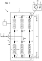
- the converter arrangement 1 comprises a converter 2, which is a modular multi-level converter (MMC).
- MMC modular multi-level converter
- the MMC is to be converted into a DC voltage Ude for converting an AC voltage of an AC voltage network 3 to which the MMC 2 is connected by means of a network transformer 4 .
- the MMC 2 comprises six converter arms 5-10 connected to each other in a double star connection.
- Each of the similarly constructed converter arms 5-10 includes two arm inductances 11, 12 and a series connection of switching modules SM. in the in figure 1 illustrated embodiment, all switching modules SM are constructed in the same way, but this is generally not necessary.
- the number of switching modules SM in each converter branch 5-10 is basically arbitrary and can be adapted to the respective application.
- the switching modules SM can be full-bridge switching modules or half-bridge switching modules, for example.
- Each switching module SM comprises controllable semiconductor switches, e.g.
- IGBT, IGCT or the like (a full-bridge switching module has at least four semiconductor switches, a half-bridge switching module has at least two semiconductor switches), freewheeling diodes suitably assigned to the semiconductor switches, and an energy store (for example in the form of a capacitor) and a control assembly , by means of which the semiconductor switches can be controlled.
- an energy store for example in the form of a capacitor
- the power converter 2 also includes a central control device 13, which is set up to control the MMC 2 (or the control variables) and to control the switching modules SM.
- the control device 13 receives specifications from a higher-level entity with regard to the required active power and reactive power, possibly also voltage and/or current, which the control unit converts into setpoint values for control parameters, e.g. voltage and current.
- the regulation parameters can thus in particular be a voltage Uac on the AC voltage side, a current Iac on the AC voltage side, a current Idc on the DC voltage side and/or a voltage Udc on the DC voltage side.
- a voltage Udc+ between the positive DC voltage pole and the ground potential and a voltage Udc- between the negative DC voltage pole and the ground potential can be important.
- the arm current (the current flowing through one of the converter arms) is the controlled variable and the arm voltage is the manipulated variable of the converter arrangement 1.
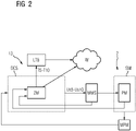
- FIG 2 is the control device 13 for the power converter 2 (e.g. the power converter 2 of figure 1 ) shown.
- the control device 13 includes a number of components.
- a module management system MMS is assigned to each of the switching modules SM of the power converter 2 .
- the MMS is set up to determine or to receive status data of the switching module SM from the associated switching module SM and to transmit this to a central current control system, current control system CCS.
- Using a Measurement & Processing Module MPM measured variables such as a current flowing in the corresponding converter arm are recorded and processed.
- the measured variables measured on the switching module SM can be used before forwarding processed or transmitted to the CCS, in particular filtered (e.g. low-pass filtered) or denoised (by filtering out high-frequency signal components).
- the current control system CCS includes a state model module ZM, which does not have to be a separate hardware module in the implementation, but can also be implemented as a software function within the control hardware.
- a state model of the power converter 2 is implemented or stored in the state model module ZM.
- the status model can be implemented, for example, in the form of one or more differential equations that can convert calculated input variables into output variables of the same type.
- At least the following input variables are included in the state model: Energy storage voltages of all switching modules SM of the converter 2 (these are supplied by the MMS), switching states of all switching modules SM (these are transmitted by the switching modules) and switching frequencies of all switching modules SM (these in the respective MMS determined and transmitted to the CCS) as well as arm voltages Uconv and arm currents Iarm of the converter arms 5-10 (transmitted/measured by the MPM).
- (Scalar) time-related temperature values T5-T10 are provided as output variables for each of the converter arms 5-10 at the output of the ZM. The temperature values are provided at time intervals that correspond to the clocking of the current control system, for example at intervals of 50 microseconds.
- control module in figure 2 not visible
- adjustments to the control voltages Us5-Us10 can be determined or calculated based on the temperature values T5-T10 and other converter variables and transmitted to the respective MMS.
- the respective MMS then translates the control voltages into suitable switching commands for the associated switching modules SM and accordingly transmits these switching commands to the individual switching modules SM.
- the temperature values T5-T10 are also transmitted to a data processing device external to the converter, which a Module LTB includes that is set up for estimating the lifetime for the power converter 2.
- the concept also offers the possibility of displaying the temperature values in real time at any time and making them available to a customer using the so-called cloud W.
- a comparison with temperature values from other power converter configurations is also possible, which means that the real-time data obtained can be used to improve operating modes and algorithms.
- knowledge of the current semiconductor losses or junction temperatures allows optimization at station level, e.g. by adjusting the cooling circuit, adjusting the setpoints, etc.
- Information about the remaining service life is provided at the output of the LTB module. This information is transmitted to the operator of the power converter 2 or made available within the cloud W. At the same time, a maintenance instruction can be generated and also made available to the operator if the estimate of the remaining service life results in a remaining service life that is below a predetermined threshold.
Landscapes
- Engineering & Computer Science (AREA)
- Power Engineering (AREA)
- Physics & Mathematics (AREA)
- General Physics & Mathematics (AREA)
- Power Conversion In General (AREA)
- Inverter Devices (AREA)
Priority Applications (2)
| Application Number | Priority Date | Filing Date | Title |
|---|---|---|---|
| EP21164446.3A EP4064546B1 (fr) | 2021-03-24 | 2021-03-24 | Convertisseur et procédé de fonctionnement du convertisseur |
| US17/703,023 US12081114B2 (en) | 2021-03-24 | 2022-03-24 | Power converter and method for operating the power converter |
Applications Claiming Priority (1)
| Application Number | Priority Date | Filing Date | Title |
|---|---|---|---|
| EP21164446.3A EP4064546B1 (fr) | 2021-03-24 | 2021-03-24 | Convertisseur et procédé de fonctionnement du convertisseur |
Publications (3)
| Publication Number | Publication Date |
|---|---|
| EP4064546A1 true EP4064546A1 (fr) | 2022-09-28 |
| EP4064546C0 EP4064546C0 (fr) | 2025-10-08 |
| EP4064546B1 EP4064546B1 (fr) | 2025-10-08 |
Family
ID=75203098
Family Applications (1)
| Application Number | Title | Priority Date | Filing Date |
|---|---|---|---|
| EP21164446.3A Active EP4064546B1 (fr) | 2021-03-24 | 2021-03-24 | Convertisseur et procédé de fonctionnement du convertisseur |
Country Status (2)
| Country | Link |
|---|---|
| US (1) | US12081114B2 (fr) |
| EP (1) | EP4064546B1 (fr) |
Cited By (1)
| Publication number | Priority date | Publication date | Assignee | Title |
|---|---|---|---|---|
| EP4628909A1 (fr) * | 2024-04-02 | 2025-10-08 | Siemens Aktiengesellschaft | Procédé de surveillance de l'état d'un dispositif électronique de puissance, programme informatique et support lisible par ordinateur |
Citations (2)
| Publication number | Priority date | Publication date | Assignee | Title |
|---|---|---|---|---|
| WO2020125968A1 (fr) | 2018-12-19 | 2020-06-25 | Siemens Aktiengesellschaft | Procédé de réglage d'un convertisseur et système convertisseur comprenant ledit convertisseur |
| CN112464443A (zh) * | 2020-11-09 | 2021-03-09 | 西南交通大学 | 一种用于电力电子变流器igbt结温波动的计算方法 |
Family Cites Families (2)
| Publication number | Priority date | Publication date | Assignee | Title |
|---|---|---|---|---|
| EP4117155A1 (fr) * | 2021-07-07 | 2023-01-11 | GE Energy Power Conversion Technology Ltd | Système de convertisseur de courant |
| WO2023183491A1 (fr) * | 2022-03-24 | 2023-09-28 | Tae Technologies, Inc. | Systèmes de communication et techniques de synchronisation pour systèmes de stockage d'énergie |
-
2021
- 2021-03-24 EP EP21164446.3A patent/EP4064546B1/fr active Active
-
2022
- 2022-03-24 US US17/703,023 patent/US12081114B2/en active Active
Patent Citations (2)
| Publication number | Priority date | Publication date | Assignee | Title |
|---|---|---|---|---|
| WO2020125968A1 (fr) | 2018-12-19 | 2020-06-25 | Siemens Aktiengesellschaft | Procédé de réglage d'un convertisseur et système convertisseur comprenant ledit convertisseur |
| CN112464443A (zh) * | 2020-11-09 | 2021-03-09 | 西南交通大学 | 一种用于电力电子变流器igbt结温波动的计算方法 |
Non-Patent Citations (5)
| Title |
|---|
| ALAVI ET AL.: "Assessment of thermal network models for estimating IGBT junction temperature of a buck converter", POWER ELECTRONICS, DRIVE SYSTEMS & TECHNOLOGIES CONFERENCE, 2017 |
| BECZKOWSKI ET AL.: "Complete Loss and Thermal Model of Power Semiconductors Including Device Rating Information", IEEE TRANSACTIONS ON POWER ELECTRONICS, 2015 |
| VELAZCO DIEGO ET AL: "IGBT Lifetime Estimation in a Modular Multilevel Converter for bidirectional point-to-point HVDC application", 2020 22ND EUROPEAN CONFERENCE ON POWER ELECTRONICS AND APPLICATIONS (EPE'20 ECCE EUROPE), EPE ASSOCIATION, 7 September 2020 (2020-09-07), pages 1 - 10, XP033835453, DOI: 10.23919/EPE20ECCEEUROPE43536.2020.9215880 * |
| ZHANG YI ET AL: "Impact of lifetime model selections on the reliability prediction of IGBT modules in modular multilevel converters", 2017 IEEE ENERGY CONVERSION CONGRESS AND EXPOSITION (ECCE), IEEE, 1 October 2017 (2017-10-01), pages 4202 - 4207, XP033247373, DOI: 10.1109/ECCE.2017.8096728 * |
| ZHANG YI ET AL: "Simplified Estimation of the Junction Temperature Fluctuation at the Output Frequency for IGBT Modules in Modular Multilevel Converters", 2018 IEEE ENERGY CONVERSION CONGRESS AND EXPOSITION (ECCE), IEEE, 23 September 2018 (2018-09-23), pages 1 - 5, XP033464223, DOI: 10.1109/ECCE.2018.8558180 * |
Cited By (2)
| Publication number | Priority date | Publication date | Assignee | Title |
|---|---|---|---|---|
| EP4628909A1 (fr) * | 2024-04-02 | 2025-10-08 | Siemens Aktiengesellschaft | Procédé de surveillance de l'état d'un dispositif électronique de puissance, programme informatique et support lisible par ordinateur |
| WO2025209721A1 (fr) * | 2024-04-02 | 2025-10-09 | Siemens Aktiengesellschaft | Procédé de surveillance de l'état d'un dispositif électronique de puissance, programme informatique et support lisible par ordinateur |
Also Published As
| Publication number | Publication date |
|---|---|
| EP4064546C0 (fr) | 2025-10-08 |
| US12081114B2 (en) | 2024-09-03 |
| EP4064546B1 (fr) | 2025-10-08 |
| US20220311327A1 (en) | 2022-09-29 |
Similar Documents
| Publication | Publication Date | Title |
|---|---|---|
| DE102011002467A1 (de) | Systeme und Verfahren zum Deaktivieren eines Matrix-Umwandlers | |
| DE60221668T2 (de) | Verfahren zur überwachung eines hochspannungsnetzes | |
| DE202016107457U1 (de) | Zweistufige Akkulösung für Rechenzentrumsbackup | |
| EP3785358B1 (fr) | Détermination d'une fonction d'un condensateur d'un circuit filtrant passif | |
| DE102011053013A1 (de) | Vorrichtung und Verfahren zur Symmetrierung der Spannungsaufteilung von in Reihe geschalteten Energiespeichern | |
| WO2019162219A1 (fr) | Réduction des ondes harmoniques dans les réseaux électriques | |
| EP4064546B1 (fr) | Convertisseur et procédé de fonctionnement du convertisseur | |
| EP4027506A1 (fr) | Convertisseur et procédé de fonctionnement du convertisseur | |
| EP3361592B1 (fr) | Procédé et dispositif de stabilisation d'une fréquence dans un réseau à tension alternative | |
| WO2020125968A1 (fr) | Procédé de réglage d'un convertisseur et système convertisseur comprenant ledit convertisseur | |
| DE102022207897A1 (de) | Elektrische Schaltung sowie Betriebsverfahren | |
| EP3449554B1 (fr) | Onduleur et procédé pour générer un courant alternatif | |
| CN117826059B (zh) | 一种供电系统内互感器的铁磁谐振故障预判断方法 | |
| DE102004030536A1 (de) | Verfahren zur Ermittlung des Risikos für einen störungsfreien Betrieb eines Frequenzumrichters | |
| EP1745535A1 (fr) | Dispositif de protection contre la surcharge thermique | |
| CN118501666B (zh) | 基于模块化可控的电力电子负载测试数据处理方法及装置 | |
| DE112019004331T5 (de) | Berührungsloses Stromversorgungssystem, Verfahren für die berührungslose Stromversorgung und Programm für die berührungslose Stromversorgung | |
| EP2933895A1 (fr) | Procédé de réglage et système doté d'un onduleur, d'une source de courant continu et d'une autre source de courant continu ou d'un écoulement de courant continu | |
| DE112019004297T5 (de) | Berührungsloses Stromversorgungssystem, Verfahren für die berührungslose Stromversorgung und Programm für die berührungslose Stromversorgung | |
| WO2024184192A1 (fr) | Ensemble constitué d'un bloc d'alimentation et d'au moins un module de mémoire tampon | |
| AT528146A1 (de) | Verfahren zur überwachung der thermischen belastung | |
| DE102024108798A1 (de) | Systeme und verfahren zum ausgleichen des ladungszustands von batteriemodulen | |
| DE19838111A1 (de) | Verfahren und Vorrichtung zur Überwachung eines Zwischenkreisfilters einer HGÜ-Anlage | |
| DE102023111849A1 (de) | Stromrichteranordnung und Verfahren zur Zustandsermittlung von Elementen eines Stromrichters | |
| WO2026012771A1 (fr) | Détermination de l'état de vieillissement de moyens de commande électrique |
Legal Events
| Date | Code | Title | Description |
|---|---|---|---|
| PUAI | Public reference made under article 153(3) epc to a published international application that has entered the european phase |
Free format text: ORIGINAL CODE: 0009012 |
|
| STAA | Information on the status of an ep patent application or granted ep patent |
Free format text: STATUS: THE APPLICATION HAS BEEN PUBLISHED |
|
| AK | Designated contracting states |
Kind code of ref document: A1 Designated state(s): AL AT BE BG CH CY CZ DE DK EE ES FI FR GB GR HR HU IE IS IT LI LT LU LV MC MK MT NL NO PL PT RO RS SE SI SK SM TR |
|
| STAA | Information on the status of an ep patent application or granted ep patent |
Free format text: STATUS: REQUEST FOR EXAMINATION WAS MADE |
|
| 17P | Request for examination filed |
Effective date: 20230303 |
|
| RBV | Designated contracting states (corrected) |
Designated state(s): AL AT BE BG CH CY CZ DE DK EE ES FI FR GB GR HR HU IE IS IT LI LT LU LV MC MK MT NL NO PL PT RO RS SE SI SK SM TR |
|
| STAA | Information on the status of an ep patent application or granted ep patent |
Free format text: STATUS: EXAMINATION IS IN PROGRESS |
|
| 17Q | First examination report despatched |
Effective date: 20231215 |
|
| GRAP | Despatch of communication of intention to grant a patent |
Free format text: ORIGINAL CODE: EPIDOSNIGR1 |
|
| STAA | Information on the status of an ep patent application or granted ep patent |
Free format text: STATUS: GRANT OF PATENT IS INTENDED |
|
| GRAJ | Information related to disapproval of communication of intention to grant by the applicant or resumption of examination proceedings by the epo deleted |
Free format text: ORIGINAL CODE: EPIDOSDIGR1 |
|
| STAA | Information on the status of an ep patent application or granted ep patent |
Free format text: STATUS: EXAMINATION IS IN PROGRESS |
|
| INTG | Intention to grant announced |
Effective date: 20250409 |
|
| INTC | Intention to grant announced (deleted) | ||
| GRAP | Despatch of communication of intention to grant a patent |
Free format text: ORIGINAL CODE: EPIDOSNIGR1 |
|
| STAA | Information on the status of an ep patent application or granted ep patent |
Free format text: STATUS: GRANT OF PATENT IS INTENDED |
|
| INTG | Intention to grant announced |
Effective date: 20250523 |
|
| GRAS | Grant fee paid |
Free format text: ORIGINAL CODE: EPIDOSNIGR3 |
|
| GRAA | (expected) grant |
Free format text: ORIGINAL CODE: 0009210 |
|
| STAA | Information on the status of an ep patent application or granted ep patent |
Free format text: STATUS: THE PATENT HAS BEEN GRANTED |
|
| AK | Designated contracting states |
Kind code of ref document: B1 Designated state(s): AL AT BE BG CH CY CZ DE DK EE ES FI FR GB GR HR HU IE IS IT LI LT LU LV MC MK MT NL NO PL PT RO RS SE SI SK SM TR |
|
| REG | Reference to a national code |
Ref country code: GB Ref legal event code: FG4D Free format text: NOT ENGLISH Ref country code: CH Ref legal event code: F10 Free format text: ST27 STATUS EVENT CODE: U-0-0-F10-F00 (AS PROVIDED BY THE NATIONAL OFFICE) Effective date: 20251008 |
|
| REG | Reference to a national code |
Ref country code: IE Ref legal event code: FG4D Free format text: LANGUAGE OF EP DOCUMENT: GERMAN |
|
| U01 | Request for unitary effect filed |
Effective date: 20251008 |
|
| U07 | Unitary effect registered |
Designated state(s): AT BE BG DE DK EE FI FR IT LT LU LV MT NL PT RO SE SI Effective date: 20251013 |
|
| PGFP | Annual fee paid to national office [announced via postgrant information from national office to epo] |
Ref country code: GB Payment date: 20260323 Year of fee payment: 6 |
|
| PG25 | Lapsed in a contracting state [announced via postgrant information from national office to epo] |
Ref country code: ES Free format text: LAPSE BECAUSE OF FAILURE TO SUBMIT A TRANSLATION OF THE DESCRIPTION OR TO PAY THE FEE WITHIN THE PRESCRIBED TIME-LIMIT Effective date: 20251008 |
|
| PG25 | Lapsed in a contracting state [announced via postgrant information from national office to epo] |
Ref country code: NO Free format text: LAPSE BECAUSE OF FAILURE TO SUBMIT A TRANSLATION OF THE DESCRIPTION OR TO PAY THE FEE WITHIN THE PRESCRIBED TIME-LIMIT Effective date: 20260108 |
|
| PG25 | Lapsed in a contracting state [announced via postgrant information from national office to epo] |
Ref country code: HR Free format text: LAPSE BECAUSE OF FAILURE TO SUBMIT A TRANSLATION OF THE DESCRIPTION OR TO PAY THE FEE WITHIN THE PRESCRIBED TIME-LIMIT Effective date: 20251008 |
|
| PG25 | Lapsed in a contracting state [announced via postgrant information from national office to epo] |
Ref country code: RS Free format text: LAPSE BECAUSE OF FAILURE TO SUBMIT A TRANSLATION OF THE DESCRIPTION OR TO PAY THE FEE WITHIN THE PRESCRIBED TIME-LIMIT Effective date: 20260108 |
|
| PG25 | Lapsed in a contracting state [announced via postgrant information from national office to epo] |
Ref country code: IS Free format text: LAPSE BECAUSE OF FAILURE TO SUBMIT A TRANSLATION OF THE DESCRIPTION OR TO PAY THE FEE WITHIN THE PRESCRIBED TIME-LIMIT Effective date: 20260208 |
|
| PG25 | Lapsed in a contracting state [announced via postgrant information from national office to epo] |
Ref country code: PL Free format text: LAPSE BECAUSE OF FAILURE TO SUBMIT A TRANSLATION OF THE DESCRIPTION OR TO PAY THE FEE WITHIN THE PRESCRIBED TIME-LIMIT Effective date: 20251008 |
|
| U20 | Renewal fee for the european patent with unitary effect paid |
Year of fee payment: 6 Effective date: 20260323 |