EP4064550B1 - Machine synchrone à aimants permanents - Google Patents
Machine synchrone à aimants permanents Download PDFInfo
- Publication number
- EP4064550B1 EP4064550B1 EP22189504.8A EP22189504A EP4064550B1 EP 4064550 B1 EP4064550 B1 EP 4064550B1 EP 22189504 A EP22189504 A EP 22189504A EP 4064550 B1 EP4064550 B1 EP 4064550B1
- Authority
- EP
- European Patent Office
- Prior art keywords
- rotor
- permanent magnet
- magnet synchronous
- synchronous machine
- angular velocity
- Prior art date
- Legal status (The legal status is an assumption and is not a legal conclusion. Google has not performed a legal analysis and makes no representation as to the accuracy of the status listed.)
- Active
Links
Images



Classifications
-
- H—ELECTRICITY
- H02—GENERATION; CONVERSION OR DISTRIBUTION OF ELECTRIC POWER
- H02P—CONTROL OR REGULATION OF ELECTRIC MOTORS, ELECTRIC GENERATORS OR DYNAMO-ELECTRIC CONVERTERS; CONTROLLING TRANSFORMERS, REACTORS OR CHOKE COILS
- H02P6/00—Arrangements for controlling synchronous motors or other dynamo-electric motors using electronic commutation dependent on the rotor position; Electronic commutators therefor
- H02P6/14—Electronic commutators
- H02P6/16—Circuit arrangements for detecting position
- H02P6/18—Circuit arrangements for detecting position without separate position detecting elements
- H02P6/182—Circuit arrangements for detecting position without separate position detecting elements using back-emf in windings
-
- H—ELECTRICITY
- H02—GENERATION; CONVERSION OR DISTRIBUTION OF ELECTRIC POWER
- H02P—CONTROL OR REGULATION OF ELECTRIC MOTORS, ELECTRIC GENERATORS OR DYNAMO-ELECTRIC CONVERTERS; CONTROLLING TRANSFORMERS, REACTORS OR CHOKE COILS
- H02P1/00—Arrangements for starting electric motors or dynamo-electric converters
- H02P1/02—Details of starting control
- H02P1/029—Restarting, e.g. after power failure
-
- H—ELECTRICITY
- H02—GENERATION; CONVERSION OR DISTRIBUTION OF ELECTRIC POWER
- H02P—CONTROL OR REGULATION OF ELECTRIC MOTORS, ELECTRIC GENERATORS OR DYNAMO-ELECTRIC CONVERTERS; CONTROLLING TRANSFORMERS, REACTORS OR CHOKE COILS
- H02P6/00—Arrangements for controlling synchronous motors or other dynamo-electric motors using electronic commutation dependent on the rotor position; Electronic commutators therefor
- H02P6/14—Electronic commutators
- H02P6/16—Circuit arrangements for detecting position
- H02P6/18—Circuit arrangements for detecting position without separate position detecting elements
-
- H—ELECTRICITY
- H02—GENERATION; CONVERSION OR DISTRIBUTION OF ELECTRIC POWER
- H02P—CONTROL OR REGULATION OF ELECTRIC MOTORS, ELECTRIC GENERATORS OR DYNAMO-ELECTRIC CONVERTERS; CONTROLLING TRANSFORMERS, REACTORS OR CHOKE COILS
- H02P6/00—Arrangements for controlling synchronous motors or other dynamo-electric motors using electronic commutation dependent on the rotor position; Electronic commutators therefor
- H02P6/20—Arrangements for starting
-
- H—ELECTRICITY
- H02—GENERATION; CONVERSION OR DISTRIBUTION OF ELECTRIC POWER
- H02P—CONTROL OR REGULATION OF ELECTRIC MOTORS, ELECTRIC GENERATORS OR DYNAMO-ELECTRIC CONVERTERS; CONTROLLING TRANSFORMERS, REACTORS OR CHOKE COILS
- H02P2207/00—Indexing scheme relating to controlling arrangements characterised by the type of motor
- H02P2207/05—Synchronous machines, e.g. with permanent magnets or DC excitation
Definitions
- the invention relates to a permanent magnet synchronous machine and a vacuum pump with such a machine as well as a method for determining an angle and an angular velocity of a rotor in a permanent magnet synchronous machine.
- the angular information i.e. the phase angle and the angular velocity
- the magnetic flux of the rotor of the permanent magnet synchronous machine is determined by measuring the voltage induced by the magnetic flux, which is also called the back electromagnetic force (back EMF).
- back EMF back electromagnetic force
- the measurement of the back EMF is technically challenging because the induced voltage to be measured due to the back EMF is approximately the same size or magnitude as the electrical background noise.
- the voltage to be measured due to the back EMF therefore has a very low signal-to-noise ratio at low speeds. This is especially true at very low speeds of around 1% of the rated or operating speed of the permanent magnet synchronous machine.
- An object of the invention is to provide a permanent magnet synchronous machine and a method which enable a reliable start-up of the permanent magnet synchronous machine from an initial state without the rotor coming to a standstill.
- the permanent magnet synchronous machine is designed in particular as a three-phase machine of a vacuum pump.
- the permanent magnet synchronous machine comprises a rotor and a device for determining an angle and an angular speed of the rotor at low speeds of the rotor below an operating speed of the permanent magnet synchronous machine by means of a retroactive electromotive force that can be detected using at least two voltages induced by the rotor, while the permanent magnet synchronous machine is operated without a sensor.
- the device for determining the angle and angular velocity of the rotor comprises an analog-digital converter, an averaging device, a Determination module and an estimation module.
- the analog-digital converter digitizes the at least two induced voltages caused by the back-acting electromotive force (back EMF).
- the averaging device calculates at least two averaged voltages over a variable number N of measured values of the at least two digitized voltages. The variable number N is determined by means of the determination module depending on the speed of the rotor.
- the estimation module estimates the angle and the angular velocity of the rotor based on the at least two averaged voltages.
- the permanent magnet synchronous machine is characterized by the fact that the signal-to-noise ratio is improved by averaging over N measured values of the two digitized voltages to such an extent that even at low rotor speeds, a reliable estimation of the angle and angular velocity is possible based on the two induced voltages that are caused by the retroactive electromotive force in sensorless operation of the permanent magnet synchronous machine.
- the signal-to-noise ratio is also increased by a factor of N elevated.
- the two induced voltages remain approximately constant over the N measured values, which is justified especially at low rotor speeds.
- the averaged voltage output by the averaging device has a new equivalent sampling frequency of f s /N.
- the averaging device downsamples with the factor N.
- the assumption that the induced voltages are constant across the N measured values is only correct, however, as long as the number N does not become too large.
- the product of N and the angular velocity or rotational frequency of the rotor must satisfy the condition that this product is small compared to 2 ⁇ f s .
- the setting module therefore sets the variable number N in such a way that this condition is met.
- the advantage of the invention is that the angle and angular velocity of the rotor can be estimated even at very low speeds based on the retroactive electromotive force and thus none of the other synchronization approaches described above are required, for example when starting up the permanent magnet synchronous machine. Since the angle and angular velocity of the rotor are determined using the induced voltage based on the retroactive electromotive force, a correct starting angle for synchronization at the beginning of the start-up phase of the permanent magnet synchronous machine can be determined even when the rotor is not at a standstill and is rotating at a low speed. Reliable start-up of the permanent magnet synchronous machine is therefore also possible for this scenario, i.e. when the rotor rotates slowly while entering the synchronization phase.
- the retroactive electromotive force is recorded using three induced voltages, which in turn can be transformed into a voltage with a real part and an imaginary part using a Clarke transformation.
- the at least two measured voltages include the real part and the imaginary part of the voltage resulting from the Clarke transformation.
- the digitized induced voltages are averaging separately for the real part and the imaginary part of the voltage after the Clarke transformation, and the estimation module takes into account both the averaged real part and the determined imaginary part of the voltage in order to estimate the angle and the angular velocity of the rotor.
- the permanent magnet synchronous machine according to the invention can be used advantageously in turbomolecular pumps, which often have a long run-down phase before coming to a standstill.
- a restart can therefore take place even when the rotor of the respective turbomolecular pump is not yet at a standstill.
- the estimation module provides a reliable estimate of the angle and angular velocity of the rotor, so that the turbomolecular pump can be started up reliably.
- the determination module initializes the number N with a predetermined value and adjusts the number N iteratively depending on the determined angular velocity.
- the averaging device can accordingly iteratively record N measured values of the at least two digitized voltages.
- the number N is thus updated at predetermined time intervals based on feedback via the determined angular velocity. For example, the signal-to-noise ratio of a signal that represents the angular velocity can be determined and the number N can be determined based on this signal-to-noise ratio. This can improve the reliability of determining the angle and angular velocity of the rotor.
- the determination module increases the number N when the angular velocity falls below a lower threshold and it reduces the number N when the angular velocity exceeds an upper threshold.
- the determination module can determine the upper and lower thresholds using a specified target value for the signal-to-noise ratio of the angular velocity. It has been shown that for each number N there is an optimal range of angular velocity in which the signal-to-noise ratio and the bandwidth, i.e. the difference between the upper and lower thresholds, are balanced. By dynamically adjusting the number N, i.e.
- the estimation module can also determine a direction of rotation of the rotor based on the at least two averaged voltages. This can be done by the estimation module identifying, for example, a zero crossing for one of the two averaged voltages and the sign for the other of the two averaged voltages.
- the determined direction of rotation of the rotor represents further information that can be used, for example, for synchronization during the start-up of the permanent magnet synchronous machine. This can improve the reliability of the synchronization and the entire start-up.
- the determination of the direction of rotation of the rotor can take place at a predetermined frequency.
- the means for determining the angle and the angular velocity of the rotor may further comprise a Kalman filter based on a mechanical model for the movement of the rotor.
- the Kalman filter may comprise an a priori estimate and an a posteriori estimate for the angle of the rotor, for the angular velocity of the rotor and for a braking torque of the rotor.
- the use of such a Kalman filter may improve the signal-to-noise ratio of the two averaged voltages. This further improves the reliability of the estimation of the angle and the angular velocity of the rotor.
- the invention further relates to a vacuum pump with a permanent magnet synchronous machine as described above.
- the invention relates to a method for determining an angle and an angular velocity of a rotor in a permanent magnet synchronous machine at low speeds of the rotor below an operating speed of the permanent magnet synchronous machine, wherein the permanent magnet synchronous machine comprises the rotor and an analog-digital converter and is operated without a sensor.
- At least two voltages induced by the rotor are recorded by means of the analog-digital converter.
- the two induced voltages represent a retroactive electromotive force (back EMF) in a sensorless operation of the permanent magnet synchronous machine.
- the at least two induced voltages are digitized by means of the analog-digital converter.
- at least two averaged voltages are calculated based on a variable number N of measured values of the at least two digitized voltages.
- the variable number N is determined depending on the speed of the rotor of the permanent magnet synchronous machine.
- the angle and the angular velocity of the rotor are estimated based on the at least two averaged voltages.
- the method thus comprises method steps which are carried out by means of the device described above for determining the angle and the angular speed of the rotor during operation or start-up of the permanent magnet synchronous machine.
- the above statements on the permanent magnet synchronous machine according to the invention therefore also apply to the method according to the invention, in particular with regard to the disclosure, the advantages and the preferred embodiments.
- the number N is initialized with a predetermined value and then iteratively adjusted depending on the determined angular velocity. During this adjustment, the number N is increased if the angular velocity falls below a lower threshold, while the number N is decreased if the angular velocity exceeds an upper threshold.
- a direction of rotation of the rotor can be determined based on the at least two averaged voltages.
- the direction of rotation of the rotor can be determined based on a zero crossing for one of the two averaged voltages and by the sign for the other of the two averaged voltages.
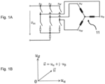
- the output voltages uv, uu, uw are used to supply corresponding electromagnets of a permanent magnet synchronous machine 17 (cf. Fig.6 ), ie for its stator, and thus for driving the permanent magnet synchronous machine 17.
- Fig. 1B shows a voltage vector u in an orthogonal coordinate system.
- the coordinates of the coordinate system correspond to the real part u ⁇ and the imaginary part u ⁇ of the stress vector.
- f (t) denotes the rotation frequency of the voltage vector, while ⁇ 0 is a phase shift.
- Fig.2 is thus the usual vector diagram of the voltage vector, whose amplitude or magnitude u rotates as a function of time t with frequency f.
- back EMF back electromotive force
- HF signal high frequency signal
- the respective background noise can be considered independent of the respective measured values and therefore as white noise.
- the signal-to-noise ratio (SNR) of the respective measured values ⁇ ⁇ and ⁇ ⁇ is obviously very low for very low speeds or angular velocities ⁇ due to the white noise.
- SNR signal-to-noise ratio
- the magnetic flux ⁇ m is fixed by the specific motor application and therefore cannot be increased to improve the signal-to-noise ratio.
- the noise components v ⁇ and v ⁇ are determined by the hardware design of the inverter 11 (see Fig.1 ) is fixed, so that the noise v ⁇ and v ⁇ cannot normally be reduced further.
- new technical means are therefore described that enable an increase in the signal-to-noise ratio to improve the estimation of the rotor angle.
- Fig.2 shows a schematic diagram of modules of a first embodiment of a device 21 for determining the angle ⁇ and the angular velocity ⁇ of the rotor. Another module and a second embodiment of the device 21 are shown in Fig.4 and 5 respectively.
- the device 21 comprises an analog-digital converter 23 which converts the analog signals uu, uv and uw of the inverter 11 from Fig.1 and converts them into corresponding digital signals u U,k , u V,k and u W,k .
- the analog signals are sampled with a given sampling frequency fs, where k denotes the k-th sampling or the k-th sample.
- the device 21 comprises a transformation device 25 which carries out a Clarke transformation on the basis of the digitized signals u U,k , u V,k and u W,k in order to obtain the two measurement signals ⁇ ⁇ ,k and ⁇ ⁇ ,k , which are described above, in digitized form.
- the device 21 comprises an averaging device 27, which determines respective mean values over the last N samples as follows: u ⁇ ⁇ , k
- the averaging starts with the k-th sample value.
- equations (12) and (13) can be approximated as follows: u ⁇ ⁇ , k
- the averaging device 27 improves the signal-to-noise ratio of its input signals u ⁇ ,k and u ⁇ ,k (cf. Fig.2 ) by a factor N .
- This improvement in the signal-to-noise ratio makes it possible for the device 21 to reliably determine the rotor angle ⁇ and the rotational speed ⁇ even at low rotor speeds.
- the number N of measured values over which an average is calculated must be set sufficiently large.
- An extreme scenario is, for example, the state after switching on the permanent magnet synchronous machine and its inverter 11.
- a controller of the permanent magnet synchronous machine, which comprises the device 21, has a priori no information regarding ⁇ , and the rotor can be operated at a sufficient speed by external loads during this time.
- the averaging of the induced voltages described above leads to the instantaneous signals with sin ⁇ k
- the device (21) may not use averaging, or it must choose a relatively small value of N. Consequently, the averaging process must be adaptive and iteratively adjusted to the current speed.
- the device 21 additionally comprises a determination module 29 which receives the output signals of the averaging device 27 as input signals and adaptively and iteratively determines the number N of voltage values over which the average is calculated.
- the determination module 29 consequently outputs a variable number N for the averaging device 27.
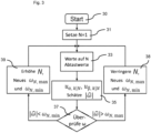
- Fig.3 the steps are shown that are carried out by the determination module 29 for adaptively determining the variable number N for the averaging device 27.
- the number N is initialized with a fixed value, in the present example with one, in order to avoid the scenario described above in which the instantaneous signals cancel each other out.
- the determination module 29 waits until N samples are available in order to then estimate the magnitude of the rotational speed ⁇ at 35 based on the input signals of the determination module 29 or the output signals u ⁇ ,k
- the estimated value for ⁇ determined at 35 is checked.
- the value of the estimated value for ⁇ at 37 is compared with a lower threshold value ⁇ N,min and with an upper threshold value ⁇ N,max .
- the upper threshold value is defined by N in such a way that aliasing is avoided.
- the lower threshold value depends on the magnetic flux or the rotor flux linkage ⁇ m and a predetermined target value for the signal-to-noise ratio. The larger the rotor flux linkage ⁇ m , the smaller the lower Threshold ⁇ N,min for a specific, predetermined target value of the signal-to-noise ratio.
- N is reduced at 38 to increase the bandwidth. This is necessary because the effective sampling rate or frequency is fs/N and a high rotation speed could cause problems with aliasing. Reducing N does indeed reduce the signal-to-noise ratio of the averaged voltages output by the averaging device 27. However, due to the increased signal-to-noise ratio of the input signals of the determination module 29, the signal-to-noise ratio is still acceptable even after reducing N at 38 due to the relatively high rotation speed ⁇ .
- the variable number N at 39 is increased to improve the signal-to-noise ratio.
- the reduced bandwidth due to the increase in N is not relevant as long as the motor actually rotates slowly and therefore there are lower demands on the bandwidth of the device 21.
- the threshold values ⁇ N,min and ⁇ N,max at 38 and 39 are reset in each iteration.
- N 100 for very low speed
- N 10 for low speed
- N 1 for a sufficient speed, which corresponds to an end to the averaging.
- a fine, adaptive adjustment of the variable adjustment N to the existing rotational speed ⁇ improves the reliability when starting up the permanent magnet synchronous machine, especially if the start-up does not take place from a standstill of the permanent magnet synchronous machine.
- an estimation module 41 is shown schematically, which represents a further component of the device 21 for determining the angle and the angular velocity of the rotor, the further components of which are shown in Fig.2
- the estimation module 41 receives as input the averaged voltages u ⁇ ,k
- the magnitude of the angular velocity ⁇ can thus be determined directly for each update ⁇ ⁇ , ⁇ and ⁇ ⁇ , ⁇ , while the direction of rotation for a set of instantaneous measured values cannot be easily derived.
- the polarity of the other of the two voltages provides clear information regarding the direction of rotation. For example, if a zero crossing of ⁇ ⁇ , ⁇ is checked, then for a positive zero crossing, i.e.
- sign ⁇ ⁇ ⁇ ⁇ sign u ⁇ ⁇ , ⁇ , if u ⁇ ⁇ , ⁇ ⁇ 1 ⁇ 0 and u ⁇ ⁇ , ⁇ > 0
- the estimation module 41 of Fig.4 an estimate of the rotor angle ⁇ ⁇ and the angular velocity ⁇ ⁇ using the above-mentioned formulas (17) to (20).
- the validity of the estimate of the rotor angle ⁇ can be extended to the range of low speeds. A further extension of the range of validity of this estimate is possible if further steps are applied to the output signals of the estimation module 41, as described below.
- Fig.5 shows a second embodiment of the device 21 for determining the angle and the angular velocity of the rotor.
- the second embodiment differs from the first embodiment described above, which in Fig. 2 to 4 shown, only in that the second embodiment of Fig.5 additionally comprises a Kalman filter 51.
- the second embodiment of the device 21 of Fig.5 thus also the analog-digital converter 23, the transformation device 25, the averaging device 27 and the determination module 29, which in connection with Fig.2 and the estimation module 41, which is described in Fig.4
- the above description of these modules therefore also applies to the second embodiment of the Facility 21 of Fig.5
- the Kalman filter 51 receives as input signals the output signals ⁇ ⁇ and ⁇ ⁇ of the estimation module 41.
- Kalman filters are well known in the art and are therefore not described in detail here. Instead, only specific aspects related to the rotation of the rotor of the permanent magnet synchronous machine are explained.
- This a posteriori estimate can be considered as the most reliable estimate and is the final output of the Kalman filter 51 and thus of the device 21.
- the device 21 provides an estimate ⁇ ⁇ ⁇ * and ⁇ ⁇ ⁇ * for the rotor angle and the angular velocity as a result of the Kalman filtering.
- the Kalman filter 51 converts the output of the estimation module 41 of Fig.4 further improved so that the range of validity or range with reliable estimation for the rotor angle can be extended to even lower speeds by means of the Kalman filter 51.
- Fig.6 shows schematically an exemplary vacuum system with a recipient 12, which is connected to a turbomolecular pump 13.
- the turbomolecular pump 13 comprises pump-active structures such as rotor disks, which belong to a rotor 14.
- the turbomolecular pump 13 in turn is connected to a Backing pump 15, which also comprises a rotor 16 as part of the pumping active elements of the backing pump 15.
- a sensorless permanent magnet synchronous machine 17 which drives the inverter 11 from Fig.1
- the rotor 16 of the backing pump is also driven by such a permanent magnet synchronous machine (not shown).
- the backing pump 15 is first switched on until a suitable negative pressure is present in the recipient 12 for switching on the turbomolecular pump 13.
- the rotors 14, 16 are not necessarily at a standstill. This applies in particular to the turbomolecular pump 13, which can have a long run-down time until the rotor 14 comes to a standstill.
- the turbomolecular pump 13 can therefore be switched on again before its rotor 14 comes to a standstill.
- the angle ⁇ and the angular velocity ⁇ of the rotor 14 cannot be reliably determined using conventional methods from the back EMF in order to be able to enter a synchronization phase during start-up. Therefore, several attempts may be required to start up the turbomolecular pump 13.
- the angle ⁇ and the angular velocity w of the rotor 14 can be determined from the back EMF even at very low speeds, so that reliable synchronization and reliable start-up of the turbomolecular pump 13 takes place.
Landscapes
- Engineering & Computer Science (AREA)
- Power Engineering (AREA)
- Control Of Motors That Do Not Use Commutators (AREA)
- Control Of Ac Motors In General (AREA)
Claims (11)
- Machine synchrone à aimants permanents (17), en particulier machine à courant triphasé d'une pompe à vide (13, 15), comprenant :un rotor (14, 16),un dispositif (21) destiné à déterminer un angle et une vitesse angulaire du rotor (14, 16), à petites vitesses de rotation du rotor (14, 16) inférieures à une vitesse de fonctionnement de la machine synchrone à aimants permanents (17), au moyen d'une force électromagnétique rétroactive qui peut être détectée à partir d'au moins deux tensions induites par le rotor (14, 16) lors d'un fonctionnement sans capteur de la machine synchrone à aimants permanents (17), ledit dispositif (21) comprenant :un convertisseur analogique-numérique (23) qui numérise lesdites au moins deux tensions induites,un dispositif de calcul de moyenne (27) qui calcule au moins deux tensions moyennées sur un nombre variable N de valeurs de mesure desdites au moins deux tensions numérisées,un module de spécification (29) qui spécifie le nombre variable N en fonction de la vitesse de rotation du rotor (14, 16), etun module d'estimation (41) qui estime l'angle et la vitesse angulaire du rotor (14, 16) à partir desdites au moins deux tensions moyennées,caractérisée en ce quele module de spécification (29) initialise le nombre N avec une valeur prédéterminée et adapte le nombre N de manière itérative en fonction de la vitesse angulaire déterminée,le module de spécification (29) augmente le nombre N lorsque la vitesse angulaire passe au-dessous d'une valeur seuil inférieure et diminue le nombre N lorsque la vitesse angulaire passe au-dessus d'une valeur seuil supérieure.
- Machine synchrone à aimants permanents (17) selon la revendication 1, dans laquelle
le module de spécification (29) détermine les seuils supérieur et inférieur à partir d'une valeur de consigne du rapport signal sur bruit de la vitesse angulaire. - Machine synchrone à aimants permanents (17) selon la revendication 1 ou 2,
dans laquelle
le module de spécification (29) diminue le nombre N lorsque la vitesse de rotation du rotor (14, 16) augmente. - Machine synchrone à aimants permanents (17) selon l'une des revendications précédentes,
dans laquelle
le module d'estimation (41) détermine un sens de rotation du rotor (14, 16) à partir desdites au moins deux tensions moyennées. - Machine synchrone à aimants permanents (17) selon la revendication 4, dans laquelle
le module d'estimation (41) identifie le sens de rotation du rotor (14, 16) à partir d'un passage par zéro pour l'une des deux tensions moyennées et à partir du signe pour l'autre des deux tensions moyennées. - Machine synchrone à aimants permanents (17) selon l'une des revendications précédentes,
dans laquelle
le dispositif (21) destiné à déterminer l'angle et la vitesse angulaire du rotor (14, 16) comprend en outre un filtre de Kalman (51) basé sur un modèle mécanique pour le mouvement du rotor (14, 16). - Machine synchrone à aimants permanents (17) selon la revendication 6, dans laquelle
le filtre de Kalman comprend une estimation à priori et une estimation à posteriori pour l'angle du rotor (14, 16), pour la vitesse angulaire du rotor (14, 16) et pour un couple de freinage du rotor (14, 16). - Pompe à vide (13, 15) comprenant une machine synchrone à aimants permanents (17) selon l'une des revendications précédentes.
- Procédé de détermination d'un angle et d'une vitesse angulaire d'un rotor (14, 16) dans une machine synchrone à aimants permanents (17), à petites vitesses de rotation du rotor (14, 16) inférieures à une vitesse de fonctionnement de la machine synchrone à aimants permanents (17), la machine synchrone à aimants permanents comprenant le rotor (14, 16) et un convertisseur analogique-numérique (23),
le procédé consistant à :détecter au moins deux tensions, induites par le rotor (14, 16), au moyen du convertisseur analogique-numérique (23), lesquelles représentent une force électromotrice rétroactive lors d'un fonctionnement sans capteur de la machine synchrone à aimants permanents (17),numériser lesdites au moins deux tensions induites au moyen du convertisseur analogique-numérique (23),calculer au moins deux tensions moyennées à partir d'un nombre variable N de valeurs de mesure desdites au moins deux tensions numérisées, le nombre variable N étant spécifié en fonction de la vitesse de rotation du rotor (14, 16), etestimer l'angle ainsi que la vitesse angulaire du rotor (14, 16) à partir desdites au moins deux tensions moyennées,caractérisé en ce quele nombre N est initialisé avec une valeur prédéterminée, et le nombre N est adapté de manière itérative en fonction de la vitesse angulaire déterminée,le nombre N est augmenté lorsque la vitesse angulaire passe au-dessous d'une valeur seuil inférieure, et le nombre N est diminué lorsque la vitesse angulaire passe au-dessus d'une valeur seuil supérieure. - Procédé selon la revendication 9,
dans lequel
un sens de rotation du rotor (14, 16) est déterminé à partir desdites au moins deux tensions moyennées. - Procédé selon la revendication 10,
dans lequel
le sens de rotation du rotor (14, 16) est identifié à partir d'un passage par zéro pour l'une des deux tensions moyennées et à partir du signe pour l'autre des deux tensions moyennées.
Priority Applications (2)
| Application Number | Priority Date | Filing Date | Title |
|---|---|---|---|
| EP22189504.8A EP4064550B1 (fr) | 2022-08-09 | 2022-08-09 | Machine synchrone à aimants permanents |
| JP2023024025A JP7590474B2 (ja) | 2022-08-09 | 2023-02-20 | 永久磁石同期機 |
Applications Claiming Priority (1)
| Application Number | Priority Date | Filing Date | Title |
|---|---|---|---|
| EP22189504.8A EP4064550B1 (fr) | 2022-08-09 | 2022-08-09 | Machine synchrone à aimants permanents |
Publications (3)
| Publication Number | Publication Date |
|---|---|
| EP4064550A2 EP4064550A2 (fr) | 2022-09-28 |
| EP4064550A3 EP4064550A3 (fr) | 2023-01-18 |
| EP4064550B1 true EP4064550B1 (fr) | 2024-06-05 |
Family
ID=82851804
Family Applications (1)
| Application Number | Title | Priority Date | Filing Date |
|---|---|---|---|
| EP22189504.8A Active EP4064550B1 (fr) | 2022-08-09 | 2022-08-09 | Machine synchrone à aimants permanents |
Country Status (2)
| Country | Link |
|---|---|
| EP (1) | EP4064550B1 (fr) |
| JP (1) | JP7590474B2 (fr) |
Family Cites Families (10)
| Publication number | Priority date | Publication date | Assignee | Title |
|---|---|---|---|---|
| JP2001119983A (ja) | 1999-10-20 | 2001-04-27 | Matsushita Electric Ind Co Ltd | モータ駆動装置 |
| GB0916543D0 (en) | 2009-09-21 | 2009-10-28 | Melexis Tessenderlo Nv | Control of sinusoidally driven brushless dc (bldc) motors |
| JP2017163663A (ja) | 2016-03-08 | 2017-09-14 | ダイキン工業株式会社 | 回転方向検出装置および空気調和機 |
| CN106026817A (zh) * | 2016-08-04 | 2016-10-12 | 上海应用技术学院 | 一种基于采用卡尔曼滤波器的滑模观测器的无速度传感器控制系统 |
| CH712828A1 (de) | 2016-08-22 | 2018-02-28 | Lakeview Innvovation Ltd | Verfahren zur sensorlosen Bestimmung der Orientierung des Rotors eines eisenlosen PMSM-Motors. |
| EP3422559B1 (fr) | 2017-06-30 | 2021-03-24 | Pfeiffer Vacuum Gmbh | Procédé de modulation pour un onduleur triphasé |
| JP2020096503A (ja) | 2018-12-04 | 2020-06-18 | アイシン精機株式会社 | モータ制御装置 |
| JP2020191724A (ja) | 2019-05-21 | 2020-11-26 | 愛三工業株式会社 | 制御装置 |
| EP3726725B1 (fr) | 2020-08-25 | 2022-07-20 | Pfeiffer Vacuum Technology AG | Procédé de démarrage d'une machine synchrone à aimant permanent sans transmetteur |
| CN112910329A (zh) * | 2021-01-25 | 2021-06-04 | 东南大学 | 一种基于移动均值滤波器的pmsm无位置传感器控制方法 |
-
2022
- 2022-08-09 EP EP22189504.8A patent/EP4064550B1/fr active Active
-
2023
- 2023-02-20 JP JP2023024025A patent/JP7590474B2/ja active Active
Also Published As
| Publication number | Publication date |
|---|---|
| EP4064550A3 (fr) | 2023-01-18 |
| JP7590474B2 (ja) | 2024-11-26 |
| EP4064550A2 (fr) | 2022-09-28 |
| JP2024024577A (ja) | 2024-02-22 |
Similar Documents
| Publication | Publication Date | Title |
|---|---|---|
| DE69607838T2 (de) | Wiederherstellung eines Gegen-EMK Signals zur Synchronisation des Antriebs eines bürsten- und sensorlosen Motors durch Neudefinieren von Antriebssignalen | |
| DE69709940T2 (de) | Vorrichtung zur erkennung der winkelposition für die lageregelung eines synchronmotors mit permanent-magnet-erregung | |
| EP1208637B1 (fr) | Procede pour la determination de la position de rotation de l'arbre d'entrainement d'un moteur a courant continu | |
| EP3288179B1 (fr) | Procédé de détermination sans capteur de l'orientation du rotor d'un moteur pmsm sans fer | |
| DE102006030362A1 (de) | Motor/Verfahren und System zum Starten eines sensorlosen Motors | |
| DE102015102565A1 (de) | Sensorloses Kommutierungsverfahren | |
| DE112008003590T5 (de) | Magnetpolpositions-Schätzverfahren für einen AC-Synchronmotor | |
| DE112007000833T5 (de) | Eine Schaltung zur Verwendung der Vorzeichenwechsel einer Motorphase und der Gegen-EMK-Ströme einer Motorphase zur Steuerung von PWM | |
| EP3861629B1 (fr) | Convertisseur multi-moteur et procédé | |
| EP2208025B1 (fr) | Procédé et dispositif de détection de la position de l'arbre de rotor d'une machine synchrone à excitation permanente | |
| DE102015105007A1 (de) | Verfahren zur sensorlosen Lagebestimmung des Rotors von elektronisch kommutierten Synchronmaschinen | |
| EP4064550B1 (fr) | Machine synchrone à aimants permanents | |
| EP3651347A2 (fr) | Procédé de régulation d'un moteur synchrone à aimants permanents, dispositif de commande et appareil sous vide | |
| EP2555417B1 (fr) | Détermination de l'angle d'un rotor d'un moteur électrique dans un véhicule équipé de capteurs de roue | |
| EP3544173B1 (fr) | Procédé et dispositif de détermination d'une position d'un rotor dans une machine électrique à commutation électronique | |
| EP1049243A2 (fr) | Méthode pour connecter un convertisseur avec un moteur asynchrone et convertisseur avec commande électric | |
| EP1070383B1 (fr) | Procede et dispositif pour la commande d'un moteur polyphase a courant continu commute electroniquement | |
| EP3881426B1 (fr) | Procédé de commutation sans capteur | |
| DE3151257A1 (de) | Synchronantrieb | |
| EP1879289B1 (fr) | Détermination de l'angle de rotation d'un moteur électrique | |
| DE102021214720A1 (de) | Steuereinrichtung zum Steuern eines bürstenlosen Gleichstrommotors unter Verwendung einer Totzeit-Kompensation | |
| DE10338996A1 (de) | Verfahren zur Steuerung eines bürstenlosen Elektromotors | |
| DE102019215854A1 (de) | Verfahren zum Betreiben eines bürstenlosen und sensorlosen mehrphasigen Elektromotors | |
| EP3625886B1 (fr) | Machine synchrone et procédé de commande de vitesse de rotation sans capteur de la machine synchrone | |
| DE102019108725A1 (de) | Steuerung für einen sensorlosen elektromotor |
Legal Events
| Date | Code | Title | Description |
|---|---|---|---|
| PUAI | Public reference made under article 153(3) epc to a published international application that has entered the european phase |
Free format text: ORIGINAL CODE: 0009012 |
|
| STAA | Information on the status of an ep patent application or granted ep patent |
Free format text: STATUS: THE APPLICATION HAS BEEN PUBLISHED |
|
| AK | Designated contracting states |
Kind code of ref document: A2 Designated state(s): AL AT BE BG CH CY CZ DE DK EE ES FI FR GB GR HR HU IE IS IT LI LT LU LV MC MK MT NL NO PL PT RO RS SE SI SK SM TR |
|
| PUAL | Search report despatched |
Free format text: ORIGINAL CODE: 0009013 |
|
| AK | Designated contracting states |
Kind code of ref document: A3 Designated state(s): AL AT BE BG CH CY CZ DE DK EE ES FI FR GB GR HR HU IE IS IT LI LT LU LV MC MK MT NL NO PL PT RO RS SE SI SK SM TR |
|
| RIC1 | Information provided on ipc code assigned before grant |
Ipc: H02P 1/02 20060101ALI20221215BHEP Ipc: H02P 21/14 20160101ALI20221215BHEP Ipc: H02P 6/18 20160101AFI20221215BHEP |
|
| STAA | Information on the status of an ep patent application or granted ep patent |
Free format text: STATUS: REQUEST FOR EXAMINATION WAS MADE |
|
| 17P | Request for examination filed |
Effective date: 20230331 |
|
| RBV | Designated contracting states (corrected) |
Designated state(s): AL AT BE BG CH CY CZ DE DK EE ES FI FR GB GR HR HU IE IS IT LI LT LU LV MC MK MT NL NO PL PT RO RS SE SI SK SM TR |
|
| STAA | Information on the status of an ep patent application or granted ep patent |
Free format text: STATUS: EXAMINATION IS IN PROGRESS |
|
| 17Q | First examination report despatched |
Effective date: 20230609 |
|
| GRAP | Despatch of communication of intention to grant a patent |
Free format text: ORIGINAL CODE: EPIDOSNIGR1 |
|
| STAA | Information on the status of an ep patent application or granted ep patent |
Free format text: STATUS: GRANT OF PATENT IS INTENDED |
|
| INTG | Intention to grant announced |
Effective date: 20240313 |
|
| GRAS | Grant fee paid |
Free format text: ORIGINAL CODE: EPIDOSNIGR3 |
|
| GRAA | (expected) grant |
Free format text: ORIGINAL CODE: 0009210 |
|
| STAA | Information on the status of an ep patent application or granted ep patent |
Free format text: STATUS: THE PATENT HAS BEEN GRANTED |
|
| AK | Designated contracting states |
Kind code of ref document: B1 Designated state(s): AL AT BE BG CH CY CZ DE DK EE ES FI FR GB GR HR HU IE IS IT LI LT LU LV MC MK MT NL NO PL PT RO RS SE SI SK SM TR |
|
| REG | Reference to a national code |
Ref country code: CH Ref legal event code: EP |
|
| REG | Reference to a national code |
Ref country code: DE Ref legal event code: R096 Ref document number: 502022000987 Country of ref document: DE |
|
| REG | Reference to a national code |
Ref country code: IE Ref legal event code: FG4D Free format text: LANGUAGE OF EP DOCUMENT: GERMAN |
|
| REG | Reference to a national code |
Ref country code: LT Ref legal event code: MG9D |
|
| PG25 | Lapsed in a contracting state [announced via postgrant information from national office to epo] |
Ref country code: BG Free format text: LAPSE BECAUSE OF FAILURE TO SUBMIT A TRANSLATION OF THE DESCRIPTION OR TO PAY THE FEE WITHIN THE PRESCRIBED TIME-LIMIT Effective date: 20240605 |
|
| REG | Reference to a national code |
Ref country code: NL Ref legal event code: MP Effective date: 20240605 |
|
| PG25 | Lapsed in a contracting state [announced via postgrant information from national office to epo] |
Ref country code: HR Free format text: LAPSE BECAUSE OF FAILURE TO SUBMIT A TRANSLATION OF THE DESCRIPTION OR TO PAY THE FEE WITHIN THE PRESCRIBED TIME-LIMIT Effective date: 20240605 Ref country code: FI Free format text: LAPSE BECAUSE OF FAILURE TO SUBMIT A TRANSLATION OF THE DESCRIPTION OR TO PAY THE FEE WITHIN THE PRESCRIBED TIME-LIMIT Effective date: 20240605 |
|
| PG25 | Lapsed in a contracting state [announced via postgrant information from national office to epo] |
Ref country code: GR Free format text: LAPSE BECAUSE OF FAILURE TO SUBMIT A TRANSLATION OF THE DESCRIPTION OR TO PAY THE FEE WITHIN THE PRESCRIBED TIME-LIMIT Effective date: 20240906 |
|
| PG25 | Lapsed in a contracting state [announced via postgrant information from national office to epo] |
Ref country code: ES Free format text: LAPSE BECAUSE OF FAILURE TO SUBMIT A TRANSLATION OF THE DESCRIPTION OR TO PAY THE FEE WITHIN THE PRESCRIBED TIME-LIMIT Effective date: 20240605 |
|
| PG25 | Lapsed in a contracting state [announced via postgrant information from national office to epo] |
Ref country code: LV Free format text: LAPSE BECAUSE OF FAILURE TO SUBMIT A TRANSLATION OF THE DESCRIPTION OR TO PAY THE FEE WITHIN THE PRESCRIBED TIME-LIMIT Effective date: 20240605 |
|
| PG25 | Lapsed in a contracting state [announced via postgrant information from national office to epo] |
Ref country code: NO Free format text: LAPSE BECAUSE OF FAILURE TO SUBMIT A TRANSLATION OF THE DESCRIPTION OR TO PAY THE FEE WITHIN THE PRESCRIBED TIME-LIMIT Effective date: 20240905 Ref country code: LV Free format text: LAPSE BECAUSE OF FAILURE TO SUBMIT A TRANSLATION OF THE DESCRIPTION OR TO PAY THE FEE WITHIN THE PRESCRIBED TIME-LIMIT Effective date: 20240605 Ref country code: HR Free format text: LAPSE BECAUSE OF FAILURE TO SUBMIT A TRANSLATION OF THE DESCRIPTION OR TO PAY THE FEE WITHIN THE PRESCRIBED TIME-LIMIT Effective date: 20240605 Ref country code: GR Free format text: LAPSE BECAUSE OF FAILURE TO SUBMIT A TRANSLATION OF THE DESCRIPTION OR TO PAY THE FEE WITHIN THE PRESCRIBED TIME-LIMIT Effective date: 20240906 Ref country code: FI Free format text: LAPSE BECAUSE OF FAILURE TO SUBMIT A TRANSLATION OF THE DESCRIPTION OR TO PAY THE FEE WITHIN THE PRESCRIBED TIME-LIMIT Effective date: 20240605 Ref country code: ES Free format text: LAPSE BECAUSE OF FAILURE TO SUBMIT A TRANSLATION OF THE DESCRIPTION OR TO PAY THE FEE WITHIN THE PRESCRIBED TIME-LIMIT Effective date: 20240605 Ref country code: BG Free format text: LAPSE BECAUSE OF FAILURE TO SUBMIT A TRANSLATION OF THE DESCRIPTION OR TO PAY THE FEE WITHIN THE PRESCRIBED TIME-LIMIT Effective date: 20240605 Ref country code: RS Free format text: LAPSE BECAUSE OF FAILURE TO SUBMIT A TRANSLATION OF THE DESCRIPTION OR TO PAY THE FEE WITHIN THE PRESCRIBED TIME-LIMIT Effective date: 20240905 |
|
| PG25 | Lapsed in a contracting state [announced via postgrant information from national office to epo] |
Ref country code: NL Free format text: LAPSE BECAUSE OF FAILURE TO SUBMIT A TRANSLATION OF THE DESCRIPTION OR TO PAY THE FEE WITHIN THE PRESCRIBED TIME-LIMIT Effective date: 20240605 |
|
| PG25 | Lapsed in a contracting state [announced via postgrant information from national office to epo] |
Ref country code: NL Free format text: LAPSE BECAUSE OF FAILURE TO SUBMIT A TRANSLATION OF THE DESCRIPTION OR TO PAY THE FEE WITHIN THE PRESCRIBED TIME-LIMIT Effective date: 20240605 |
|
| PG25 | Lapsed in a contracting state [announced via postgrant information from national office to epo] |
Ref country code: PT Free format text: LAPSE BECAUSE OF FAILURE TO SUBMIT A TRANSLATION OF THE DESCRIPTION OR TO PAY THE FEE WITHIN THE PRESCRIBED TIME-LIMIT Effective date: 20241007 |
|
| PG25 | Lapsed in a contracting state [announced via postgrant information from national office to epo] |
Ref country code: PT Free format text: LAPSE BECAUSE OF FAILURE TO SUBMIT A TRANSLATION OF THE DESCRIPTION OR TO PAY THE FEE WITHIN THE PRESCRIBED TIME-LIMIT Effective date: 20241007 |
|
| PG25 | Lapsed in a contracting state [announced via postgrant information from national office to epo] |
Ref country code: PL Free format text: LAPSE BECAUSE OF FAILURE TO SUBMIT A TRANSLATION OF THE DESCRIPTION OR TO PAY THE FEE WITHIN THE PRESCRIBED TIME-LIMIT Effective date: 20240605 |
|
| PG25 | Lapsed in a contracting state [announced via postgrant information from national office to epo] |
Ref country code: EE Free format text: LAPSE BECAUSE OF FAILURE TO SUBMIT A TRANSLATION OF THE DESCRIPTION OR TO PAY THE FEE WITHIN THE PRESCRIBED TIME-LIMIT Effective date: 20240605 |
|
| PG25 | Lapsed in a contracting state [announced via postgrant information from national office to epo] |
Ref country code: IS Free format text: LAPSE BECAUSE OF FAILURE TO SUBMIT A TRANSLATION OF THE DESCRIPTION OR TO PAY THE FEE WITHIN THE PRESCRIBED TIME-LIMIT Effective date: 20241005 |
|
| PG25 | Lapsed in a contracting state [announced via postgrant information from national office to epo] |
Ref country code: SK Free format text: LAPSE BECAUSE OF FAILURE TO SUBMIT A TRANSLATION OF THE DESCRIPTION OR TO PAY THE FEE WITHIN THE PRESCRIBED TIME-LIMIT Effective date: 20240605 Ref country code: RO Free format text: LAPSE BECAUSE OF FAILURE TO SUBMIT A TRANSLATION OF THE DESCRIPTION OR TO PAY THE FEE WITHIN THE PRESCRIBED TIME-LIMIT Effective date: 20240605 |
|
| PG25 | Lapsed in a contracting state [announced via postgrant information from national office to epo] |
Ref country code: SM Free format text: LAPSE BECAUSE OF FAILURE TO SUBMIT A TRANSLATION OF THE DESCRIPTION OR TO PAY THE FEE WITHIN THE PRESCRIBED TIME-LIMIT Effective date: 20240605 |
|
| PG25 | Lapsed in a contracting state [announced via postgrant information from national office to epo] |
Ref country code: SM Free format text: LAPSE BECAUSE OF FAILURE TO SUBMIT A TRANSLATION OF THE DESCRIPTION OR TO PAY THE FEE WITHIN THE PRESCRIBED TIME-LIMIT Effective date: 20240605 Ref country code: SK Free format text: LAPSE BECAUSE OF FAILURE TO SUBMIT A TRANSLATION OF THE DESCRIPTION OR TO PAY THE FEE WITHIN THE PRESCRIBED TIME-LIMIT Effective date: 20240605 Ref country code: RO Free format text: LAPSE BECAUSE OF FAILURE TO SUBMIT A TRANSLATION OF THE DESCRIPTION OR TO PAY THE FEE WITHIN THE PRESCRIBED TIME-LIMIT Effective date: 20240605 Ref country code: PL Free format text: LAPSE BECAUSE OF FAILURE TO SUBMIT A TRANSLATION OF THE DESCRIPTION OR TO PAY THE FEE WITHIN THE PRESCRIBED TIME-LIMIT Effective date: 20240605 Ref country code: IS Free format text: LAPSE BECAUSE OF FAILURE TO SUBMIT A TRANSLATION OF THE DESCRIPTION OR TO PAY THE FEE WITHIN THE PRESCRIBED TIME-LIMIT Effective date: 20241005 Ref country code: EE Free format text: LAPSE BECAUSE OF FAILURE TO SUBMIT A TRANSLATION OF THE DESCRIPTION OR TO PAY THE FEE WITHIN THE PRESCRIBED TIME-LIMIT Effective date: 20240605 |
|
| REG | Reference to a national code |
Ref country code: DE Ref legal event code: R097 Ref document number: 502022000987 Country of ref document: DE |
|
| PLBE | No opposition filed within time limit |
Free format text: ORIGINAL CODE: 0009261 |
|
| STAA | Information on the status of an ep patent application or granted ep patent |
Free format text: STATUS: NO OPPOSITION FILED WITHIN TIME LIMIT |
|
| PG25 | Lapsed in a contracting state [announced via postgrant information from national office to epo] |
Ref country code: DK Free format text: LAPSE BECAUSE OF FAILURE TO SUBMIT A TRANSLATION OF THE DESCRIPTION OR TO PAY THE FEE WITHIN THE PRESCRIBED TIME-LIMIT Effective date: 20240605 |
|
| PG25 | Lapsed in a contracting state [announced via postgrant information from national office to epo] |
Ref country code: LU Free format text: LAPSE BECAUSE OF NON-PAYMENT OF DUE FEES Effective date: 20240809 |
|
| PG25 | Lapsed in a contracting state [announced via postgrant information from national office to epo] |
Ref country code: MC Free format text: LAPSE BECAUSE OF FAILURE TO SUBMIT A TRANSLATION OF THE DESCRIPTION OR TO PAY THE FEE WITHIN THE PRESCRIBED TIME-LIMIT Effective date: 20240605 |
|
| 26N | No opposition filed |
Effective date: 20250306 |
|
| REG | Reference to a national code |
Ref country code: BE Ref legal event code: MM Effective date: 20240831 |
|
| PG25 | Lapsed in a contracting state [announced via postgrant information from national office to epo] |
Ref country code: BE Free format text: LAPSE BECAUSE OF NON-PAYMENT OF DUE FEES Effective date: 20240831 |
|
| PG25 | Lapsed in a contracting state [announced via postgrant information from national office to epo] |
Ref country code: FR Free format text: LAPSE BECAUSE OF NON-PAYMENT OF DUE FEES Effective date: 20240831 |
|
| PG25 | Lapsed in a contracting state [announced via postgrant information from national office to epo] |
Ref country code: IE Free format text: LAPSE BECAUSE OF NON-PAYMENT OF DUE FEES Effective date: 20240809 |
|
| PG25 | Lapsed in a contracting state [announced via postgrant information from national office to epo] |
Ref country code: SE Free format text: LAPSE BECAUSE OF FAILURE TO SUBMIT A TRANSLATION OF THE DESCRIPTION OR TO PAY THE FEE WITHIN THE PRESCRIBED TIME-LIMIT Effective date: 20240605 |
|
| PGFP | Annual fee paid to national office [announced via postgrant information from national office to epo] |
Ref country code: IT Payment date: 20250901 Year of fee payment: 4 |
|
| PGFP | Annual fee paid to national office [announced via postgrant information from national office to epo] |
Ref country code: AT Payment date: 20251020 Year of fee payment: 4 |
|
| PGFP | Annual fee paid to national office [announced via postgrant information from national office to epo] |
Ref country code: CZ Payment date: 20250804 Year of fee payment: 4 |
|
| PGFP | Annual fee paid to national office [announced via postgrant information from national office to epo] |
Ref country code: DE Payment date: 20251029 Year of fee payment: 4 |
|
| PG25 | Lapsed in a contracting state [announced via postgrant information from national office to epo] |
Ref country code: CY Free format text: LAPSE BECAUSE OF FAILURE TO SUBMIT A TRANSLATION OF THE DESCRIPTION OR TO PAY THE FEE WITHIN THE PRESCRIBED TIME-LIMIT; INVALID AB INITIO Effective date: 20220809 |
|
| PG25 | Lapsed in a contracting state [announced via postgrant information from national office to epo] |
Ref country code: HU Free format text: LAPSE BECAUSE OF FAILURE TO SUBMIT A TRANSLATION OF THE DESCRIPTION OR TO PAY THE FEE WITHIN THE PRESCRIBED TIME-LIMIT; INVALID AB INITIO Effective date: 20220809 |
|
| REG | Reference to a national code |
Ref country code: CH Ref legal event code: H13 Free format text: ST27 STATUS EVENT CODE: U-0-0-H10-H13 (AS PROVIDED BY THE NATIONAL OFFICE) Effective date: 20260324 |
|
| PG25 | Lapsed in a contracting state [announced via postgrant information from national office to epo] |
Ref country code: CH Free format text: LAPSE BECAUSE OF NON-PAYMENT OF DUE FEES Effective date: 20250831 |