EP4064585B1 - Procédé pour rapporter des informations d'état de canal dans un système de communication sans fil, et dispositif associé - Google Patents
Procédé pour rapporter des informations d'état de canal dans un système de communication sans fil, et dispositif associé Download PDFInfo
- Publication number
- EP4064585B1 EP4064585B1 EP20851866.2A EP20851866A EP4064585B1 EP 4064585 B1 EP4064585 B1 EP 4064585B1 EP 20851866 A EP20851866 A EP 20851866A EP 4064585 B1 EP4064585 B1 EP 4064585B1
- Authority
- EP
- European Patent Office
- Prior art keywords
- csi
- information
- index
- pusch
- coefficients
- Prior art date
- Legal status (The legal status is an assumption and is not a legal conclusion. Google has not performed a legal analysis and makes no representation as to the accuracy of the status listed.)
- Active
Links
Images






Classifications
-
- H—ELECTRICITY
- H04—ELECTRIC COMMUNICATION TECHNIQUE
- H04B—TRANSMISSION
- H04B7/00—Radio transmission systems, i.e. using radiation field
- H04B7/02—Diversity systems; Multi-antenna system, i.e. transmission or reception using multiple antennas
- H04B7/04—Diversity systems; Multi-antenna system, i.e. transmission or reception using multiple antennas using two or more spaced independent antennas
- H04B7/06—Diversity systems; Multi-antenna system, i.e. transmission or reception using multiple antennas using two or more spaced independent antennas at the transmitting station
- H04B7/0613—Diversity systems; Multi-antenna system, i.e. transmission or reception using multiple antennas using two or more spaced independent antennas at the transmitting station using simultaneous transmission
- H04B7/0615—Diversity systems; Multi-antenna system, i.e. transmission or reception using multiple antennas using two or more spaced independent antennas at the transmitting station using simultaneous transmission of weighted versions of same signal
- H04B7/0619—Diversity systems; Multi-antenna system, i.e. transmission or reception using multiple antennas using two or more spaced independent antennas at the transmitting station using simultaneous transmission of weighted versions of same signal using feedback from receiving side
- H04B7/0621—Feedback content
- H04B7/0626—Channel coefficients, e.g. channel state information [CSI]
-
- H—ELECTRICITY
- H04—ELECTRIC COMMUNICATION TECHNIQUE
- H04B—TRANSMISSION
- H04B7/00—Radio transmission systems, i.e. using radiation field
- H04B7/02—Diversity systems; Multi-antenna system, i.e. transmission or reception using multiple antennas
- H04B7/04—Diversity systems; Multi-antenna system, i.e. transmission or reception using multiple antennas using two or more spaced independent antennas
- H04B7/0413—MIMO systems
- H04B7/0456—Selection of precoding matrices or codebooks, e.g. using matrices antenna weighting
- H04B7/0478—Special codebook structures directed to feedback optimisation
-
- H—ELECTRICITY
- H04—ELECTRIC COMMUNICATION TECHNIQUE
- H04L—TRANSMISSION OF DIGITAL INFORMATION, e.g. TELEGRAPHIC COMMUNICATION
- H04L5/00—Arrangements affording multiple use of the transmission path
- H04L5/003—Arrangements for allocating sub-channels of the transmission path
- H04L5/0048—Allocation of pilot signals, i.e. of signals known to the receiver
-
- H—ELECTRICITY
- H04—ELECTRIC COMMUNICATION TECHNIQUE
- H04L—TRANSMISSION OF DIGITAL INFORMATION, e.g. TELEGRAPHIC COMMUNICATION
- H04L5/00—Arrangements affording multiple use of the transmission path
- H04L5/003—Arrangements for allocating sub-channels of the transmission path
- H04L5/0048—Allocation of pilot signals, i.e. of signals known to the receiver
- H04L5/005—Allocation of pilot signals, i.e. of signals known to the receiver of common pilots, i.e. pilots destined for multiple users or terminals
-
- H—ELECTRICITY
- H04—ELECTRIC COMMUNICATION TECHNIQUE
- H04L—TRANSMISSION OF DIGITAL INFORMATION, e.g. TELEGRAPHIC COMMUNICATION
- H04L5/00—Arrangements affording multiple use of the transmission path
- H04L5/003—Arrangements for allocating sub-channels of the transmission path
- H04L5/0053—Allocation of signalling, i.e. of overhead other than pilot signals
-
- H—ELECTRICITY
- H04—ELECTRIC COMMUNICATION TECHNIQUE
- H04L—TRANSMISSION OF DIGITAL INFORMATION, e.g. TELEGRAPHIC COMMUNICATION
- H04L5/00—Arrangements affording multiple use of the transmission path
- H04L5/003—Arrangements for allocating sub-channels of the transmission path
- H04L5/0053—Allocation of signalling, i.e. of overhead other than pilot signals
- H04L5/0057—Physical resource allocation for CQI
-
- H—ELECTRICITY
- H04—ELECTRIC COMMUNICATION TECHNIQUE
- H04L—TRANSMISSION OF DIGITAL INFORMATION, e.g. TELEGRAPHIC COMMUNICATION
- H04L5/00—Arrangements affording multiple use of the transmission path
- H04L5/0091—Signalling for the administration of the divided path, e.g. signalling of configuration information
- H04L5/0094—Indication of how sub-channels of the path are allocated
-
- H—ELECTRICITY
- H04—ELECTRIC COMMUNICATION TECHNIQUE
- H04W—WIRELESS COMMUNICATION NETWORKS
- H04W24/00—Supervisory, monitoring or testing arrangements
- H04W24/10—Scheduling measurement reports ; Arrangements for measurement reports
-
- H—ELECTRICITY
- H04—ELECTRIC COMMUNICATION TECHNIQUE
- H04W—WIRELESS COMMUNICATION NETWORKS
- H04W52/00—Power management, e.g. Transmission Power Control [TPC] or power classes
- H04W52/04—Transmission power control [TPC]
- H04W52/06—TPC algorithms
- H04W52/14—Separate analysis of uplink or downlink
- H04W52/146—Uplink power control
-
- H—ELECTRICITY
- H04—ELECTRIC COMMUNICATION TECHNIQUE
- H04W—WIRELESS COMMUNICATION NETWORKS
- H04W52/00—Power management, e.g. Transmission Power Control [TPC] or power classes
- H04W52/04—Transmission power control [TPC]
- H04W52/18—TPC being performed according to specific parameters
- H04W52/24—TPC being performed according to specific parameters using SIR [Signal to Interference Ratio] or other wireless path parameters
- H04W52/247—TPC being performed according to specific parameters using SIR [Signal to Interference Ratio] or other wireless path parameters where the output power of a terminal is based on a path parameter sent by another terminal
-
- H—ELECTRICITY
- H04—ELECTRIC COMMUNICATION TECHNIQUE
- H04W—WIRELESS COMMUNICATION NETWORKS
- H04W52/00—Power management, e.g. Transmission Power Control [TPC] or power classes
- H04W52/04—Transmission power control [TPC]
- H04W52/18—TPC being performed according to specific parameters
- H04W52/28—TPC being performed according to specific parameters using user profile, e.g. mobile speed, priority or network state, e.g. standby, idle or non-transmission
- H04W52/281—TPC being performed according to specific parameters using user profile, e.g. mobile speed, priority or network state, e.g. standby, idle or non-transmission taking into account user or data type priority
-
- H—ELECTRICITY
- H04—ELECTRIC COMMUNICATION TECHNIQUE
- H04W—WIRELESS COMMUNICATION NETWORKS
- H04W52/00—Power management, e.g. Transmission Power Control [TPC] or power classes
- H04W52/04—Transmission power control [TPC]
- H04W52/30—Transmission power control [TPC] using constraints in the total amount of available transmission power
- H04W52/32—TPC of broadcast or control channels
- H04W52/325—Power control of control or pilot channels
-
- H—ELECTRICITY
- H04—ELECTRIC COMMUNICATION TECHNIQUE
- H04W—WIRELESS COMMUNICATION NETWORKS
- H04W72/00—Local resource management
- H04W72/12—Wireless traffic scheduling
- H04W72/1263—Mapping of traffic onto schedule, e.g. scheduled allocation or multiplexing of flows
- H04W72/1268—Mapping of traffic onto schedule, e.g. scheduled allocation or multiplexing of flows of uplink data flows
-
- H—ELECTRICITY
- H04—ELECTRIC COMMUNICATION TECHNIQUE
- H04W—WIRELESS COMMUNICATION NETWORKS
- H04W72/00—Local resource management
- H04W72/50—Allocation or scheduling criteria for wireless resources
- H04W72/54—Allocation or scheduling criteria for wireless resources based on quality criteria
- H04W72/542—Allocation or scheduling criteria for wireless resources based on quality criteria using measured or perceived quality
-
- H—ELECTRICITY
- H04—ELECTRIC COMMUNICATION TECHNIQUE
- H04L—TRANSMISSION OF DIGITAL INFORMATION, e.g. TELEGRAPHIC COMMUNICATION
- H04L25/00—Baseband systems
- H04L25/02—Details ; arrangements for supplying electrical power along data transmission lines
- H04L25/0202—Channel estimation
- H04L25/0224—Channel estimation using sounding signals
-
- H—ELECTRICITY
- H04—ELECTRIC COMMUNICATION TECHNIQUE
- H04L—TRANSMISSION OF DIGITAL INFORMATION, e.g. TELEGRAPHIC COMMUNICATION
- H04L5/00—Arrangements affording multiple use of the transmission path
- H04L5/0001—Arrangements for dividing the transmission path
- H04L5/0003—Two-dimensional division
- H04L5/0005—Time-frequency
- H04L5/0007—Time-frequency the frequencies being orthogonal, e.g. OFDM(A) or DMT
- H04L5/001—Time-frequency the frequencies being orthogonal, e.g. OFDM(A) or DMT the frequencies being arranged in component carriers
-
- H—ELECTRICITY
- H04—ELECTRIC COMMUNICATION TECHNIQUE
- H04L—TRANSMISSION OF DIGITAL INFORMATION, e.g. TELEGRAPHIC COMMUNICATION
- H04L5/00—Arrangements affording multiple use of the transmission path
- H04L5/003—Arrangements for allocating sub-channels of the transmission path
- H04L5/0058—Allocation criteria
- H04L5/0073—Allocation arrangements that take into account other cell interferences
-
- Y—GENERAL TAGGING OF NEW TECHNOLOGICAL DEVELOPMENTS; GENERAL TAGGING OF CROSS-SECTIONAL TECHNOLOGIES SPANNING OVER SEVERAL SECTIONS OF THE IPC; TECHNICAL SUBJECTS COVERED BY FORMER USPC CROSS-REFERENCE ART COLLECTIONS [XRACs] AND DIGESTS
- Y02—TECHNOLOGIES OR APPLICATIONS FOR MITIGATION OR ADAPTATION AGAINST CLIMATE CHANGE
- Y02D—CLIMATE CHANGE MITIGATION TECHNOLOGIES IN INFORMATION AND COMMUNICATION TECHNOLOGIES [ICT], I.E. INFORMATION AND COMMUNICATION TECHNOLOGIES AIMING AT THE REDUCTION OF THEIR OWN ENERGY USE
- Y02D30/00—Reducing energy consumption in communication networks
- Y02D30/70—Reducing energy consumption in communication networks in wireless communication networks
Definitions
- the present disclosure relates to a wireless communication system, and more particularly, to a method for reporting channel state information in consideration of a payload of channel state information, and a device for supporting the same.
- Mobile communication systems have been developed to guarantee user activity while providing voice services.
- Mobile communication systems are expanding their services from voice only to data.
- Current soaring data traffic is depleting resources and users' demand for higher-data rate services is leading to the need for more advanced mobile communication systems. Examples are described in:
- Next-generation mobile communication systems are required to meet, e.g., handling of explosively increasing data traffic, significant increase in per-user transmission rate, working with a great number of connecting devices, and support for very low end-to-end latency and high-energy efficiency.
- various research efforts are underway for various technologies, such as dual connectivity, massive multiple input multiple output (MIMO), in-band full duplex, non-orthogonal multiple access (NOMA), super wideband support, and device networking.
- MIMO massive multiple input multiple output
- NOMA non-orthogonal multiple access
- super wideband support and device networking.
- the present disclosure proposes a method of reporting channel state information (CSI) in a wireless communication system.
- CSI channel state information
- the present disclosure considers the payload of the channel state information (CSI), and when the size of the payload of the channel state information is greater than the resource capacity allocated for the CSI, proposes a method of omitting a part of the CSI.
- CSI channel state information
- the present disclosure proposes a method of determining a priority of CSI parameters in order to perform omission of a part of channel state information.
- the present disclosure proposes a method of reporting CSI by configuring the CSI into a first part and a second part.
- the present disclosure proposes a method for transmitting channel state information based on PUSCH power control.
- a method of reporting channel state information (CSI) through physical uplink shared channel (PUSCH) , by a user equipment (UE), in a wireless communication system comprising: receiving, from a base station, configuration information, wherein the configuration information includes (i) a CSI related configuration and (ii) a configuration related to transmission power control of the PUSCH; receiving, from the base station, a CSI-reference signal(CSI-RS) based on the CSI related configuration; computing CSI based on the CSI-RS, wherein the CSI includes information related to coefficients, wherein each of elements of the information related to the coefficients is classified as a plurality of groups based on a priority value, and wherein the priority value increases as an order in which a higher index and a lower index of indexes of a frequency domain related to the elements are sequentially crossed based on a predefined specific index; and transmitting, to the base station, a CSI report configured by omitting
- the priority value is determined based on i) a layer index ii) an index of a spatial domain related to each element and iii) an index of a frequency domain related to each elements.
- the priority value increases in an ascending order of the index of the spatial domain.
- a priority of i) the index of the spatial domain of a strongest coefficient and ii) an index of the spatial domain corresponding to a beam having an opposite polarization with respect to a beam corresponding to the strongest coefficient is the highest.
- the predefined specific index is related to an index in the frequency domain of a strongest coefficient among the coefficients.
- the CSI report consists of a first part and a second part, and wherein the CSI report is omitted in the second part.
- the CSI report further includes information related to omission of the portion among the plurality of groups.
- the information related to the omission includes at least one of (i) information on whether to omit, (ii) information on an object to be omitted or (iii) information on a quantity to be omitted.
- the information related with coefficients includes at least one of information on an amplitude coefficient, ii) information on a phase coefficient, or iii) bitmap information related to the amplitude coefficient and the phase coefficient.
- a resource region for transmitting the PUSCH is allocated based on the CSI related configuration, and wherein a payload size of the computed CSI exceeds the resource region.
- a user equipment to report channel state information (CSI) through physical uplink shared channel (PUSCH) in a wireless communication system
- the UE comprising: one or more transceivers; one or more processors; and one or more memories storing instructions for operations executed by the one or more processors and coupled to the one or more processors, wherein the operations comprise: receiving, from a base station, configuration information, wherein the configuration information includes (i) a CSI related configuration and (ii) a configuration related to transmission power control of the PUSCH; receiving, from the base station, a CSI-reference signal(CSI-RS) based on the CSI related configuration; computing CSI based on the CSI-RS, wherein the CSI includes information related to coefficients, wherein each of elements of the information related to the coefficients is classified as a plurality of groups based on a priority value, and wherein the priority value increases as an order in which a higher index and a lower index of indexes of a frequency domain related to the elements
- a method of receiving channel state information (CSI) through physical uplink shared channel (PUSCH), by a base station, in a wireless communication system comprising: transmitting, to a user equipment (UE), configuration information, wherein the configuration information includes (i) a CSI related configuration and (ii) a configuration related to transmission power control of the PUSCH; transmitting, to the UE, a CSI-reference signal(CSI-RS) based on the CSI related configuration; and receiving, from the UE, a CSI report including CSI measured based on the CSI-RS, through the PUSCH, wherein the CSI includes information related to coefficients, wherein each of elements of the information related to the coefficients is classified as a plurality of groups based on a priority value, wherein the priority value increases as an order in which a higher index and a lower index of indexes of a frequency domain related to the elements are sequentially crossed based on a predefined specific index, wherein the CSI report is configured by
- a base station to receive channel state information (CSI) through physical uplink shared channel (PUSCH) in a wireless communication system
- the base station comprising: one or more transceivers; one or more processors; and one or more memories storing instructions for operations executed by the one or more processors and coupled to the one or more processors, wherein the operations comprise: transmitting, to a user equipment (UE), configuration information, wherein the configuration information includes (i) a CSI related configuration and (ii) a configuration related to transmission power control of the PUSCH; transmitting, to the UE, a CSI-reference signal(CSI-RS) based on the CSI related configuration; and receiving, from the UE, a CSI report including CSI measured based on the CSI-RS, through the PUSCH, wherein the CSI includes information related to coefficients, wherein each of elements of the information related to the coefficients is classified as a plurality of groups based on a priority value, wherein the priority value increases as an order in which a
- an apparatus comprising one or more memories and one or more processors operatively coupled to the one or more memories, the apparatus comprising: wherein the one or more processors controls the apparatus to: receive, from a base station, configuration information, wherein the configuration information includes (i) a CSI related configuration and (ii) a configuration related to transmission power control of the PUSCH; receive, from the base station, a CSI-reference signal(CSI-RS) based on the CSI related configuration; compute CSI based on the CSI-RS, wherein the CSI includes information related to coefficients, wherein each of elements of the information related to the coefficients is classified as a plurality of groups based on a priority value, and wherein the priority value increases as an order in which a higher index and a lower index of indexes of a frequency domain related to the elements are sequentially crossed based on a predefined specific index; and transmit, to the base station, a CSI report configured by omitting, among the plurality of groups, a
- one or more non-transitory computer-readable media storing one or more instructions, the one or more instructions executable by one or more processors comprising: an instruction instructs a user equipment (UE) to: receive, from a base station, configuration information, wherein the configuration information includes (i) a CSI related configuration and (ii) a configuration related to transmission power control of the PUSCH; receive, from the base station, a CSI-reference signal(CSI-RS) based on the CSI related configuration; compute CSI based on the CSI-RS, wherein the CSI includes information related to coefficients, wherein each of elements of the information related to the coefficients is classified as a plurality of groups based on a priority value, and wherein the priority value increases as an order in which a higher index and a lower index of indexes of a frequency domain related to the elements are sequentially crossed based on a predefined specific index; and transmit, to the base station, a CSI report configured by omitting, among the plurality
- the base station it is possible to report the channel state information to the base station in consideration of the payload size of the channel state information.
- channel state information it is possible to report channel state information by performing an omitting operation in consideration of a priority of components of the channel state information to minimize a loss of information within the allocated resource capacity.
- known structures and devices may be omitted or illustrated in a block diagram format based on core functions of each structure and device.
- downlink means communication from the base station to the terminal and uplink (UL) means communication from the terminal to the base station.
- DL downlink
- UL uplink
- a transmitter may be part of the base station, and a receiver may be part of the terminal.
- uplink the transmitter may be part of the terminal and the receiver may be part of the base station.
- the base station may be expressed as a first communication device and the terminal may be expressed as a second communication device.
- a base station may be replaced with terms including a fixed station, a Node B, an evolved-NodeB (eNB), a Next Generation NodeB (gNB), a base transceiver system (BTS), an access point (AP), a network (5G network), an AI system, a road side unit (RSU), a vehicle, a robot, an Unmanned Aerial Vehicle (UAV), an Augmented Reality (AR) device, a Virtual Reality (VR) device, and the like.
- the terminal may be fixed or mobile and may be replaced with terms including a User Equipment (UE), a Mobile Station (MS), a user terminal (UT), a Mobile Subscriber Station (MSS), a Subscriber Station (SS), an Advanced Mobile Station (AMS), a Wireless Terminal (WT), a Machine-Type Communication (MTC) device, a Machine-to-Machine (M2M) device, and a Device-to-Device (D2D) device, the vehicle, the robot, an AI module, the Unmanned Aerial Vehicle (UAV), the Augmented Reality (AR) device, the Virtual Reality (VR) device, and the like.
- UAV Unmanned Aerial Vehicle
- AR Augmented Reality
- VR Virtual Reality
- the following technology may be used in various radio access system including CDMA, FDMA, TDMA, OFDMA, SC-FDMA, and the like.
- the CDMA may be implemented as radio technology such as Universal Terrestrial Radio Access (UTRA) or CDMA2000.
- the TDMA may be implemented as radio technology such as a global system for mobile communications (GSM)/general packet radio service (GPRS)/enhanced data rates for GSM evolution (EDGE).
- GSM global system for mobile communications
- GPRS general packet radio service
- EDGE enhanced data rates for GSM evolution
- the OFDMA may be implemented as radio technology such as Institute of Electrical and Electronics Engineers (IEEE) 802.11 (Wi-Fi), IEEE 802.16 (WiMAX), IEEE 802.20, Evolved UTRA (E-UTRA), or the like.
- the UTRA is a part of Universal Mobile Telecommunications System (UMTS).
- 3rd Generation Partnership Project (3GPP) Long Term Evolution (LTE) is a part of Evolved UMTS (E-UMTS) using the E-UTRA and LTE-Advanced (A)/LTE-A pro is an evolved version of the 3GPP LTE.
- 3GPP NR New Radio or New Radio Access Technology
- 3GPP LTE/LTE-A/LTE-A pro is an evolved version of the 3GPP LTE/LTE-A/LTE-A pro.
- LTE means technology after 3GPP TS 36.xxx Release 8.
- LTE technology after 3GPP TS 36.xxx Release 10 is referred to as the LTE-A
- LTE technology after 3GPP TS 36.xxx Release 13 is referred to as the LTE-A pro.
- the 3GPP NR means technology after TS 38.xxx Release 15.
- the LTE/NR may be referred to as a 3GPP system.
- "xxx" means a standard document detail number. Matters disclosed in a standard document opened before the present disclosure may be referred to for a background art, terms, abbreviations, etc., used for describing the present disclosure. For example, the following documents may be referred to.
- next generation communication As more and more communication devices require larger communication capacity, there is a need for improved mobile broadband communication compared to the existing radio access technology (RAT).
- massive machine type communications MTCs
- MTCs massive machine type communications
- a communication system design considering a service/UE sensitive to reliability and latency is being discussed.
- the introduction of next generation radio access technology considering enhanced mobile broadband communication (eMBB), massive MTC (mMTC), ultra-reliable and low latency communication (URLLC) is discussed, and in the present disclosure, the technology is called new RAT for convenience.
- the NR is an expression representing an example of 5G radio access technology (RAT).
- Three major requirement areas of 5G include (1) an enhanced mobile broadband (eMBB) area, (2) a massive machine type communication (mMTC) area and (3) an ultra-reliable and low latency communications (URLLC) area.
- eMBB enhanced mobile broadband
- mMTC massive machine type communication
- URLLC ultra-reliable and low latency communications
- KPI key performance indicator
- eMBB is far above basic mobile Internet access and covers media and entertainment applications in abundant bidirectional tasks, cloud or augmented reality.
- Data is one of key motive powers of 5G, and dedicated voice services may not be first seen in the 5G era.
- voice will be processed as an application program using a data connection simply provided by a communication system.
- Major causes for an increased traffic volume include an increase in the content size and an increase in the number of applications that require a high data transfer rate.
- Streaming service (audio and video), dialogue type video and mobile Internet connections will be used more widely as more devices are connected to the Internet.
- Such many application programs require connectivity always turned on in order to push real-time information and notification to a user.
- cloud storage is a special use case that tows the growth of an uplink data transfer rate.
- 5G is also used for remote business of cloud.
- Entertainment for example, cloud game and video streaming are other key elements which increase a need for the mobile broadband ability. Entertainment is essential in the smartphone and tablet anywhere including high mobility environments, such as a train, a vehicle and an airplane.
- Another use case is augmented reality and information search for entertainment. In this case, augmented reality requires very low latency and an instant amount of data.
- one of the most expected 5G use case relates to a function capable of smoothly connecting embedded sensors in all fields, that is, mMTC.
- mMTC massive machine type
- IoT devices will reach 20.4 billions.
- the industry IoT is one of areas in which 5G performs major roles enabling smart city, asset tracking, smart utility, agriculture and security infra.
- URLLC includes a new service which will change the industry through remote control of major infra and a link having ultra reliability/low available latency, such as a self-driving vehicle.
- a level of reliability and latency is essential for smart grid control, industry automation, robot engineering, drone control and adjustment.
- 5G may supplement fiber-to-the-home (FTTH) and cable-based broadband (or DOCSIS) as means for providing a stream evaluated from gigabits per second to several hundreds of mega bits per second.
- FTTH fiber-to-the-home
- DOCSIS cable-based broadband
- Such fast speed is necessary to deliver TV with resolution of 4K or more (6K, 8K or more) in addition to virtual reality and augmented reality.
- Virtual reality (VR) and augmented reality (AR) applications include immersive sports games.
- a specific application program may require a special network configuration. For example, in the case of VR game, in order for game companies to minimize latency, a core server may need to be integrated with the edge network server of a network operator.
- An automotive is expected to be an important and new motive power in 5G, along with many use cases for the mobile communication of an automotive. For example, entertainment for a passenger requires a high capacity and a high mobility mobile broadband at the same time. The reason for this is that future users continue to expect a high-quality connection regardless of their location and speed.
- Another use example of the automotive field is an augmented reality dashboard.
- the augmented reality dashboard overlaps and displays information, identifying an object in the dark and notifying a driver of the distance and movement of the object, over a thing seen by the driver through a front window.
- a wireless module enables communication between automotives, information exchange between an automotive and a supported infrastructure, and information exchange between an automotive and other connected devices (e.g., devices accompanied by a pedestrian).
- a safety system guides alternative courses of a behavior so that a driver can drive more safely, thereby reducing a danger of an accident.
- a next step will be a remotely controlled or self-driven vehicle. This requires very reliable, very fast communication between different self-driven vehicles and between an automotive and infra. In the future, a self-driven vehicle may perform all driving activities, and a driver will be focused on things other than traffic, which cannot be identified by an automotive itself.
- Technical requirements of a self-driven vehicle require ultra-low latency and ultra-high speed reliability so that traffic safety is increased up to a level which cannot be achieved by a person.
- a smart city and smart home mentioned as a smart society will be embedded as a high-density radio sensor network.
- the distributed network of intelligent sensors will identify the cost of a city or home and a condition for energy-efficient maintenance.
- a similar configuration may be performed for each home. All of a temperature sensor, a window and heating controller, a burglar alarm and home appliances are wirelessly connected. Many of such sensors are typically a low data transfer rate, low energy and a low cost. However, for example, real-time HD video may be required for a specific type of device for surveillance.
- a smart grid collects information, and interconnects such sensors using digital information and a communication technology so that the sensors operate based on the information.
- the information may include the behaviors of a supplier and consumer, and thus the smart grid may improve the distribution of fuel, such as electricity, in an efficient, reliable, economical, production-sustainable and automated manner.
- the smart grid may be considered to be another sensor network having small latency.
- a health part owns many application programs which reap the benefits of mobile communication.
- a communication system can support remote treatment providing clinical treatment at a distant place. This helps to reduce a barrier for the distance and can improve access to medical services which are not continuously used at remote farming areas. Furthermore, this is used to save life in important treatment and an emergency condition.
- a radio sensor network based on mobile communication can provide remote monitoring and sensors for parameters, such as the heart rate and blood pressure.
- Logistics and freight tracking is an important use case for mobile communication, which enables the tracking inventory and packages anywhere using a location-based information system.
- the logistics and freight tracking use case typically requires a low data speed, but a wide area and reliable location information.
- a new RAT system including NR uses an OFDM transmission scheme or a similar transmission scheme thereto.
- the new RAT system may follow OFDM parameters different from OFDM parameters of LTE.
- the new RAT system may follow numerology of conventional LTE/LTE-A as it is or have a larger system bandwidth (e.g., 100 MHz).
- one cell may support a plurality of numerologies. In other words, UEs that operate with different numerologies may coexist in one cell.
- the numerology corresponds to one subcarrier spacing in a frequency domain.
- Different numerologies may be defined by scaling reference subcarrier spacing to an integer N.
- eLTE eNB The eLTE eNB is the evolution of eNB that supports connectivity to EPC and NGC.
- gNB A node which supports the NR as well as connectivity to NGC.
- New RAN A radio access network which supports either NR or E-UTRA or interfaces with the NGC.
- Network slice is a network created by the operator customized to provide an optimized solution for a specific market scenario which demands specific requirements with end-to-end scope.
- Network function is a logical node within a network infrastructure that has well-defined external interfaces and well-defined functional behaviour.
- NG-C A control plane interface used on NG2 reference points between new RAN and NGC.
- NG-U A user plane interface used on NG3 references points between new RAN and NGC.
- Non-standalone NR A deployment configuration where the gNB requires an LTE eNB as an anchor for control plane connectivity to EPC, or requires an eLTE eNB as an anchor for control plane connectivity to NGC.
- Non-standalone E-UTRA A deployment configuration where the eLTE eNB requires a gNB as an anchor for control plane connectivity to NGC.
- User plane gateway A termination point of NG-U interface.
- FIG. 1 illustrates an example of an overall structure of a NR system to which a method proposed in the present disclosure is applicable..
- an NG-RAN consists of gNBs that provide an NG-RA user plane (new AS sublayer/PDCP/RLC/MAC/PHY) and control plane (RRC) protocol terminations for a user equipment (UE).
- NG-RA user plane new AS sublayer/PDCP/RLC/MAC/PHY
- RRC control plane
- the gNBs are interconnected with each other by means of an Xn interface.
- the gNBs are also connected to an NGC by means of an NG interface.
- the gNBs are connected to an access and mobility management function (AMF) by means of an N2 interface and to a user plane function (UPF) by means of an N3 interface.
- AMF access and mobility management function
- UPF user plane function
- multiple numerologies may be supported.
- the numerologies may be defined by subcarrier spacing and a CP (Cyclic Prefix) overhead. Spacing between the plurality of subcarriers may be derived by scaling basic subcarrier spacing into an integer N (or ⁇ ).
- N or ⁇
- a numerology to be used may be selected independent of a frequency band.
- OFDM orthogonal frequency division multiplexing
- the NR supports multiple numerologies (or subcarrier spacing (SCS)) for supporting various 5G services. For example, when the SCS is 15 kHz, a wide area in traditional cellular bands is supported and when the SCS is 30 kHz/60 kHz, dense-urban, lower latency, and wider carrier bandwidth are supported, and when the SCS is 60 kHz or higher therethan, a bandwidth larger than 24.25 GHz is supported in order to overcome phase noise.
- SCS subcarrier spacing
- NR frequency band is defined as frequency ranges of two types (FR1 and FR2).
- FR1 and FR2 may be configured as shown in Table 2 below. Further, FR2 may mean a millimeter wave (mmW).
- mmW millimeter wave
- ⁇ f max 480 ⁇ 10 3
- N f 4096.
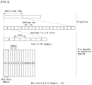
- FIG. 2 illustrates a relation between an uplink frame and a downlink frame in a wireless communication system to which a method proposed in the present disclosure is applicable.
- slots are numbered in increasing order of n s ⁇ ⁇ 0 , ... , N subframe slots , ⁇ ⁇ 1 within a subframe and are numbered in increasing order of n s , f ⁇ ⁇ 0 , ... , N frame slots , ⁇ ⁇ 1 within a radio frame.
- One slot consists of consecutive OFDM symbols of N symb ⁇ , and N symb ⁇ is determined depending on a numerology used and slot configuration.
- the start of slots n s ⁇ in a subframe is aligned in time with the start of OFDM symbols n s ⁇ N symb ⁇ in the same subframe.
- Not all UEs are able to transmit and receive at the same time, and this means that not all OFDM symbols in a downlink slot or an uplink slot are available to be used.
- Table 3 represents the number N symb slot of OFDM symbols per slot, the number N slot frame , ⁇ of slots per radio frame, and the number N slot subframe , ⁇ of slots per subframe in a normal CP.
- Table 4 represents the number of OFDM symbols per slot, the number of slots per radio frame, and the number of slots per subframe in an extended CP. [Table 3] ⁇ N symb slot N slot frame , ⁇ N slot subframe , ⁇ 0 14 10 1 1 14 20 2 2 14 40 4 3 14 80 8 4 14 160 16 [Table 4] ⁇ N symb slot N slot frame , ⁇ N slot subframe , ⁇ 2 12 40 4
- FIG. 3 illustrates an example of a frame structure in a NR system.
- FIG. 3 is merely for convenience of explanation and does not limit the scope of the present disclosure.
- a mini-slot may consist of 2, 4, or 7 symbols, or may consist of more symbols or less symbols.
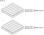
- an antenna port In regard to physical resources in the NR system, an antenna port, a resource grid, a resource element, a resource block, a carrier part, etc. may be considered.
- a resource grid consists of N RB ⁇ N sc RB subcarriers on a frequency domain, each subframe consisting of 14 ⁇ 2 ⁇ OFDM symbols, but the present disclosure is not limited thereto.
- the resource element ( k, l ) for the numerology ⁇ and the antenna port p corresponds to a complex value a k , l ⁇ p ⁇ .
- the indexes p and ⁇ may be dropped, and as a result, the complex value may be a k , l ⁇ p or a k, l .
- Point A serves as a common reference point of a resource block grid and may be obtained as follows.
- the common resource blocks are numbered from 0 and upwards in the frequency domain for subcarrier spacing configuration ⁇ .
- n CRB ⁇ k N sc RB
- Physical resource blocks are defined within a bandwidth part (BWP) and are numbered from 0 to N SWP , i size ⁇ 1 , where i is No. of the BWP.
- BWP bandwidth part
- n PRB in BWP i the common resource block
- n CRB n PRB + N BWP , i start
- N BWP , i start may be the common resource block where the BWP starts relative to the common resource block 0.
- FIG. 6 illustrates physical channels and general signal transmission used in a 3GPP system.
- the UE receives information from the eNB through Downlink (DL) and the UE transmits information from the eNB through Uplink (UL).
- the information which the eNB and the UE transmit and receive includes data and various control information and there are various physical channels according to a type/use of the information which the eNB and the UE transmit and receive.
- the UE When the UE is powered on or newly enters a cell, the UE performs an initial cell search operation such as synchronizing with the eNB (S601). To this end, the UE may receive a Primary Synchronization Signal (PSS) and a (Secondary Synchronization Signal (SSS) from the eNB and synchronize with the eNB and acquire information such as a cell ID or the like. Thereafter, the UE may receive a Physical Broadcast Channel (PBCH) from the eNB and acquire in-cell broadcast information. Meanwhile, the UE receives a Downlink Reference Signal (DL RS) in an initial cell search step to check a downlink channel status.
- PSS Primary Synchronization Signal
- SSS Secondary Synchronization Signal
- PBCH Physical Broadcast Channel
- DL RS Downlink Reference Signal
- a UE that completes the initial cell search receives a Physical Downlink Control Channel (PDCCH) and a Physical Downlink Control Channel (PDSCH) according to information loaded on the PDCCH to acquire more specific system information (S602).
- PDCCH Physical Downlink Control Channel
- PDSCH Physical Downlink Control Channel
- the UE may perform a Random Access Procedure (RACH) to the eNB (S603 to S606).
- RACH Random Access Procedure
- the UE may transmit a specific sequence to a preamble through a Physical Random Access Channel (PRACH) (S603 and S605) and receive a response message (Random Access Response (RAR) message) for the preamble through the PDCCH and a corresponding PDSCH.
- PRACH Physical Random Access Channel
- RAR Random Access Response
- a Contention Resolution Procedure may be additionally performed (S606).
- the UE that performs the above procedure may then perform PDCCH/PDSCH reception (S607) and Physical Uplink Shared Channel (PUSCH)/Physical Uplink Control Channel (PUCCH) transmission (S608) as a general uplink/downlink signal transmission procedure.
- the UE may receive Downlink Control Information (DCI) through the PDCCH.
- DCI Downlink Control Information
- the DCI may include control information such as resource allocation information for the UE and formats may be differently applied according to a use purpose.
- control information which the UE transmits to the eNB through the uplink or the UE receives from the eNB may include a downlink/uplink ACK/NACK signal, a Channel Quality Indicator (CQI), a Precoding Matrix Index (PMI), a Rank Indicator (RI), and the like.
- the UE may transmit the control information such as the CQI/PMI/RI, etc., through the PUSCH and/or PUCCH.
- CSI-RS channel state information-reference signal
- L1-RSRP layer 1
- BM beam management
- Channel state information collectively refers to information that may indicate the quality of a radio channel (or referred to as a link) formed between the UE and the antenna port.
- FIG. 7 is a flowchart illustrating an example of a CSI related procedure.
- a terminal e.g., user equipment (UE) receives, from a base station (e.g., general Node B or gNB), configuration information related to the CSI through radio resource control (RRC) signaling (step S710).
- RRC radio resource control
- the configuration information related to the CSI may include at least one of CSI-interference management (IM) resource related information, CSI measurement configuration related information, CSI resource configuration related information, CSI-RS resource related information, or CSI report configuration related information.
- IM CSI-interference management
- the CSI-IM resource related information may include CSI-IM resource information, CSI-IM resource set information, and the like.
- the CSI-IM resource set is identified by a CSI-IM resource set identifier (ID), and one resource set includes at least one CSI-IM resource.
- Each CSI-IM resource is identified by a CSI-IM resource ID.
- the CSI resource configuration related information may be expressed as CSI-ResourceConfig IE.
- the CSI resource configuration related information defines a group including at least one of a non-zero power (NZP) CSI-RS resource set, a CSI-IM resource set, or a CSI-SSB resource set.
- the CSI resource configuration related information may include a CSI-RS resource set list and the CSI-RS resource set list may include at least one of a NZP CSI-RS resource set list, a CSI-IM resource set list, or a CSI-SSB resource set list.
- the CSI-RS resource set is identified by a CSI-RS resource set ID, and one resource set includes at least one CSI-RS resource.
- Each CSI-RS resource is identified by a CSI-RS resource ID.
- Table 5 represents an example of NZP CSI-RS resource set IE.
- parameters e.g., a BM related 'repetition' parameter and a tracking related 'trs-Info' parameter
- a BM related 'repetition' parameter and a tracking related 'trs-Info' parameter representing the usage of CSI-RS may be configured for each NZP CSI-RS resource set.
- the repetition parameter corresponding to the higher layer parameter corresponds to 'CSI-RS-ResourceRep' of L1 parameter.
- the CSI report configuration related information includes a reportConfigType parameter representing a time domain behavior and a reportQuantity parameter representing a CSI related quantity for reporting.
- the time domain behavior may be periodic, aperiodic, or semi-persistent.
- the CSI report configuration related information may be expressed as CSI-ReportConfig IE, and Table 6 below represents an example of CSI-ReportConfig IE.
- the UE measures CSI based on configuration information related to the CSI (step S720).
- the CSI measurement may include (1) a CSI-RS reception process of the UE (step S721) and (2) a process of computing the CSI through the received CSI-RS (step S722), and a detailed description thereof will be described below.
- resource element (RE) mapping of a CSI-RS resource is configured time and frequency domains by higher layer parameter CSI-RS-ResourceMapping.
- Table 7 represents an example of CSI-RS-ResourceMapping IE.
- a density (D) represents a density of the CSI-RS resource measured in RE/port/physical resource block (PRB), and nrofPorts represents the number of antenna ports.
- the UE reports the measured CSI to the BS (step S730).
- the UE may skip the report.
- the UE may report the measured CSI to the BS.
- the case where the quantity is configured to 'none (or No report)' is a case of triggering aperiodic TRS or a case where repetition is configured.
- the report of the UE may be skipped.
- the NR system supports more flexible and dynamic CSI measurement and reporting.
- the CSI measurement may include a procedure of acquiring the CSI by receiving the CSI-RS and computing the received CSI-RS.
- CM periodic/semi-persistent/periodic channel measurement
- IM interference measurement
- a 4 port NZP CSI-RS RE pattern is used for configuring the CSI-IM.
- each port emulates an interference layer having (a preferable channel and) precoded NZP CSI-RS. This is for intra-cell interference measurement with respect to a multi-user case and primarily targets MU interference.
- the BS transmits the precoded NZP CSI-RS to the UE on each port of the configured NZP CSI-RS based IMR.
- the UE assumes a channel/interference layer for each port and measures interference.
- the BS or the network indicates a subset of NZP CSI-RS resources through the DCI with respect to channel/interference measurement.
- Each CSI resource setting 'CSI-ResourceConfig' includes a configuration for S ⁇ 1 CSI resource set (given by higher layer parameter csi-RS-ResourceSetList).
- the CSI resource setting corresponds to the CSI-RS-resourcesetlist.
- S represents the number of configured CSI-RS resource sets.
- the configuration for S ⁇ 1 CSI resource set includes each CSI resource set including CSI-RS resources (constituted by NZP CSI-RS or CSI IM) and an SS/PBCH block (SSB) resource used for L1-RSRP computation.
- CSI-RS resources constituted by NZP CSI-RS or CSI IM
- SSB SS/PBCH block
- Each CSI resource setting is positioned in a DL BWP (bandwidth part) identified by a higher layer parameter bwp-id.
- all CSI resource settings linked to CSI reporting setting have the same DL BWP.
- a time domain behavior of the CSI-RS resource within the CSI resource setting included in CSI-ResourceConfig IE is indicated by higher layer parameter resourceType and may be configured to be aperiodic, periodic, or semi-persistent.
- the number S of configured CSI-RS resource sets is limited to '1' with respect to periodic and semi-persistent CSI resource settings.
- Periodicity and slot offset which are configured are given in numerology of associated DL BWP as given by bwp-id with respect to the periodic and semi-persistent CSI resource settings.
- the same time domain behavior is configured with respect to CSI-ResourceConfig.
- the same time domain behavior is configured with respect to CSI-ResourceConfig.
- CM channel measurement
- IM interference measurement
- channel measurement resource may be NZP CSI-RS and interference measurement resource (IMR) may be NZP CSI-RS for CSI-IM and IM.
- CSI-IM (or ZP CSI-RS for IM) is primarily used for inter-cell interference measurement.
- NZP CSI-RS for IM is primarily used for intra-cell interference measurement from multi-users.
- the UE may assume CSI-RS resource(s) for channel measurement and CSI-IM/NZP CSI-RS resource(s) for interference measurement configured for one CSI reporting are 'QCL-TypeD' for each resource.
- the resource setting may mean a resource set list.
- One reporting setting may be connected with a maximum of three resource settings.
- Each CSI-ReportConfig is linked to periodic or semi-persistent resource setting with respect to semi-persistent or periodic CSI.
- each CSI-RS resource for channel measurement is associated with/related to the CSI-IM resource for each resource by an order of CSI-RS resources and CSI-IM resources within a corresponding resource set.
- the number of CSI-RS resources for channel measurement is equal to the number of CSI-IM resources.
- the UE when the interference measurement is performed in the NZP CSI-RS, the UE does not expect to be configured as one or more NZP CSI-RS resources in the associated resource set within the resource setting for channel measurement.
- the UE assumes the followings.
- time and frequency resources which may be used by the UE are controlled by the BS.
- the channel state information may include at least one of a channel quality indicator (CQI), a precoding matrix indicator (PMI), a CSI-RS resource indicator (CRI), an SS/PBCH block resource indicator (SSBRI), a layer indicator (LI), a rank indicator (RI), and L1-RSRP.
- CQI channel quality indicator
- PMI precoding matrix indicator
- CSI-RS resource indicator CRI
- SSBRI SS/PBCH block resource indicator
- LI layer indicator
- RI rank indicator
- L1-RSRP L1-RSRP
- the UE is configured by a higher layer as N ⁇ 1 CSI-ReportConfig reporting setting, M ⁇ 1 CSI-ResourceConfig resource setting, and a list (provided by aperiodicTriggerStateList and semiPersistentOnPUSCH) of one or two trigger states.
- N ⁇ 1 CSI-ReportConfig reporting setting
- M ⁇ 1 CSI-ResourceConfig resource setting
- a list (provided by aperiodicTriggerStateList and semiPersistentOnPUSCH) of one or two trigger states.
- each trigger state includes the channel and an associated CSI-ReportConfigs list optionally indicating resource set IDs for interference.
- each trigger state includes one associated CSI-ReportConfig.
- time domain behavior of CSI reporting supports periodic, semi-persistent, and aperiodic.
- the periodicity and the slot offset are configured as the RRC and the CSI reporting to separate MAC CE/DCI is activated/deactivated.
- the periodicity of the SP CSI reporting is configured through the RRC, but the slot offset is not configured through the RRC, and the SP CSI reporting is activated/deactivated by DCI (format 0_1).
- Separated RNTI SP-CSI C-RNTI is used with respect to the SP CSI reporting on the PUSCH.
- An initial CSI reporting timing follows a PUSCH time domain allocation value indicated in the DCI and a subsequent CSI reporting timing follows a periodicity configured through the RRC.
- DCI format 0_1 may include a CSI request field and may activate/deactivate a specific configured SP-CSI trigger state.
- the SP CSI reporting has the same or similar activation/deactivation as a mechanism having data transmission on SPS PUSCH.
- an AP CSI-RS timing is configured by the RRC and a timing for AP CSI reporting is dynamically controlled by the DCI.
- the NR does not adopt a scheme (for example, transmitting RI, WB PMI/CQI, and SB PMI/CQI in order) of dividing and reporting the CSI in multiple reporting instances applied to PUCCH based CSI reporting in the LTE. Instead, the NR restricts specific CSI reporting not to be configured in the short/long PUCCH and a CSI omission rule is defined.
- a PUSCH symbol/slot location is dynamically indicated by the DCI.
- candidate slot offsets are configured by the RRC.
- slot offset(Y) is configured for each reporting setting.
- slot offset K2 is configured separately.
- the low latency CSI is a WB CSI that includes up to 4 ports Type-I codebook or up to 4-ports non-PMI feedback CSI.
- the high latency CSI refers to CSI other than the low latency CSI.
- Z, Z' is defined in a unit of OFDM symbols.
- Z represents a minimum CSI processing time from the reception of the aperiodic CSI triggering DCI to the execution of the CSI reporting.
- Z' represents a minimum CSI processing time from the reception of the CSI-RS for channel/interference to the execution of the CSI reporting.
- the UE reports the number of CSIs which may be simultaneously calculated.
- Table 8 below is related to the CSI reporting configuration defined in TS38.214.
- Table 9 below is information related to activation/deactivation/trigger by MAC-CE related to Semi-Persistent/Aperiodic CSI reporting defined in TS38.321.
- Table 9 5.18.2 Activation/Deactivation of Semi-persistent CSI-RS/CSI-IM resource set
- the network may activate and deactivate the configured Semi-persistent CSI-RS/CSI-IM resource sets of a Serving Cell by sending the SP CSI-RS/CSI-IM Resource Set Activation/Deactivation MAC CE described in subclause 6.1.3.12.
- the configured Semi-persistent CSI-RS/CSI-IM resource sets are initially deactivated upon configuration and after a handover.
- the MAC entity shall: 1> if the MAC entity receives an SP CSI-RS/CSI-IM Resource Set Activation/Deactivation MAC CE on a Serving Cell: 2> indicate to lower layers the information regarding the SP CSI-RS/CSI-IM Resource Set Activation/Deactivation MAC CE. 5.18.3 Aperiodic CSI Trigger State subselection
- the network may select among the configured aperiodic CSI trigger states of a Serving Cell by sending the Aperiodic CSI Trigger State Subselection MAC CE described in subclause 6.1.3.13.
- the MAC entity shall: 1> if the MAC entity receives an Aperiodic CSI trigger State Subselection MAC CE on a Serving Cell: 2> indicate to lower layers the information regarding Aperiodic CSI trigger State Subselection MAC CE.
- Aperiodic CSI reporting performed in PUSCH supports broadband and sub-band frequency segmentation.
- the aperiodic CSI reporting performed in the PUSCH supports Type I and Type II CSI.
- SP CSI reporting for PUSCH supports type I and type II CSI having wide band and subband frequency granularity.
- the PUSCH resource and modulation and coding scheme (MCS) for the SP CSI reporting are semi-permanently allocated by UL DCI.
- CSI reporting for PUSCH may include part 1 and part 2.
- Part 1 is used to identify the number of information bits in Part 2.
- Part 1 is fully delivered before Part 2.
- the UE may omit part of the second CSI.
- Omission of Part 2 CSI is determined according to priorities shown in Table 10, and priority 0 is the highest priority and 2N Rep is the lowest priority.
- NRep denotes the number of CSI reportings in one slot.
- Part 2 CSI information for a specific priority level When Part 2 CSI information for a specific priority level is omitted, the UE omits all information of the corresponding priority level.
- c MCS denotes a target PUSCH code rate
- ⁇ offset CSI ⁇ 2 denotes a CSI offset value.
- Part 2 CSI is omitted level by level, starting with the lowest-priority level and the lowest-priority level until the UCI code ratio is less than or equal to c T .
- ⁇ offset CSI ⁇ part 1 and ⁇ offset CSI ⁇ part 2 denotes a CSI offset value
- r CSI-1 is based on a code rate calculated by the UE or signaled by DCI.
- the UE may be configured with a number of periodic CSI reporting corresponding to the CSI reporting configuration indication configured with one or more higher layers.
- the associated CSI measurement link and CSI resource configuration are configured as a higher layer.
- periodic CSI reporting supports type I CSI based on a wide bandwidth.
- the UE performs SP CSI reporting for the PUCCH in slot n + 3 N slot subframe , ⁇ + 1 after the HARQ-ACK corresponding to the PDSCH carrying the selection command is transmitted in a slot n.
- the selection command includes one or more report setting indications in which the associated CSI resource settings are configured.
- the SP CSI report supports the Type I CSI.
- the SP CSI report of PUCCH format 2 supports type I CSI with wide bandwidth frequency granularity.
- the SP CSI report supports the type I sub-band CSI and type II CSI with the wideband frequency granularity.
- the CSI payload carried by PUCCH format 2 and PUCCH format 3 or 4 is the same as CRI (when reported) regardless of RI.
- PUCCH format 3 or 4 the type I CSI subband payload is divided into two parts.
- the first part (Part 1) includes the RI, (reported) CRI and (reported) CQI of the first code word.
- the second part (Part 2) includes the PMI, and when RI > 4, the second part (Part 2) includes the CQI of the second code word.
- SP CSI reporting performed in PUCCH format 3 or 4 supports type II CSI feedback, but only supports part 1 of type II CSI feedback.
- CSI reporting may depend on UE performance.
- Type II CSI reporting delivered in PUCCH format 3 or 4 (of which only Part 1 is applicable) is calculated independently of type II CSI reporting performed in PUSCH.
- each PUCCH resource is configured for each candidate UL BWP.
- the CSI reporting is performed when the CSI reported BWP is the active BWP, otherwise the CSI reporting is temporarily stopped. This operation also applies to the case of SP CSI of PUCCH. For PUSCH-based SP CSI reporting, the corresponding CSI reporting is automatically deactivated when BWP switching occurs.
- the PUCCH format may be classified into a short PUCCH or a long PUCCH.
- the PUCCH formats 0 and 2 may be referred to as short PUCCHs, and the PUCCH formats 1, 3 and 4 may be referred to as long PUCCHs.
- the short PUCCH-based CSI reporting and the long PUCCH-based CSI reporting will be described in detail below.
- the short PUCCH-based CSI reporting is used only for wideband CSI reporting.
- the short PUCCH-based CSI reporting has the same payload regardless of the RI/CRI of the given slot to avoid blind decoding.
- the size of the information payload may be different between the maximum CSI-RS ports of the CSI-RS configured in the CSI-RS resource set.
- a padding bit is added to RI/CRI/PMI/CQI before the encoding procedure for equalizing the payload associated with/related to different RI/CRI values.
- RI/CRI/PMI/CQI may be encoded with a padding bit if necessary.
- the long PUCCH-based CSI reporting may use the same solution as the short PUCCH-based CSI reporting.
- Part 1 may have a fixed payload according to the number of ports, CSI type, RI limitation, etc., and Part 2 may have various payload sizes according to Part 1.
- the CSI/RI may be encoded first to determine the payload of PMI/CQI.
- Type II CSI report may convey only Part 1.
- a terminal for example, User Equipment, UE
- a mobile device controlling the transmission power of a terminal and/or a mobile device may be referred to as uplink power control.
- a transmission power control method may be applied to satisfy the requirements (for example, Signal-to-Noise Ratio (SNR), Bit Error Ratio (BER), or Block Error Ratio (BLER)) of a base station (for example, gNB or eNB).
- SNR Signal-to-Noise Ratio
- BER Bit Error Ratio
- BLER Block Error Ratio
- the power control described above may be performed according to the open-loop power control method or the closed-loop power control method.
- the open-loop power control method controls transmission power without feedback from a transmitting device (for example, a BS) to a receiving device (for example, a UE) and/or without feedback from the receiving device to the transmitting device.
- a transmitting device for example, a BS
- a receiving device for example, a UE
- the UE may receive a pilot channel/signal from the BS and estimate the strength of the received power using the received pilot channel/signal.
- the UE may control the transmission power using the estimated strength of the received power.
- the closed-loop power control method controls transmission power based on the feedback from the transmitting device to the receiving device and/or based on the feedback from the receiving device to the transmitting device.
- the BS receives a pilot channel/signal from the UE and, based on the power level, SNR, BER, or BLER measured using the received pilot channel/signal, determines the optimum power level of the UE.
- the BS may transmit information (namely, feedback) on the determined optimum power level to the UE through a control channel, and the UE may control transmission power using the feedback provided by the BS.
- a transmission occasion for PUCCH and/or PUCCH (namely, a transmission time unit) (i) may be defined by the slot index n s , the first symbol S within a slot, or the number of consecutive symbols L within a frame with a specific system frame number (SFN).
- the power control method is described based on the assumption that the UE performs PUSCH transmission.
- the corresponding method may be extended to be applied to other types of uplink data channels supported in a wireless communication system.
- the UE may calculate a linear power value of the transmission power determined by Eq. 3 below. Afterward, the corresponding UE may control the transmission power based on the calculated linear power value by considering the number of antenna ports and/or SRS ports.
- UL BWP active UL bandwidth part
- the UE may determine the PUSCH transmission power P PUSCH, b , f , c ( i , j , q d ,l ) dBm for the PUSCH transmission occasion (i) based on Eq. 3 below.
- P PUSCH , b , f , c i j q d l min P CMAX , f , c i , P O_PUSCH , b , f , c j + 10 log 10 2 ⁇ ⁇ M RB , b , f , c PUSCH i + ⁇ b , f , c j ⁇ PL b , f , c q d + ⁇ TF , b , f , c i + f b , f , c i l dBm
- the index j represents the index for the open-loop power control parameter (for example, P O , ⁇ ), and a maximum of 32 parameter sets may be configured for each cell.
- the index q d represents the index of a DL RS resource for pathloss (PL) measurement (for example, PL b,f,c ( q d )), and a maximum of 4 measurements may be configured for each cell.
- the index l represents the closed-loop power control process index, and a maximum of 2 processes may be configured for each cell.
- P O (for example, P O_PUSCH, b , f , c ( j )) is the parameter broadcast as part of system information and may represent the target received power at the receiver side.
- the corresponding P O value may be configured by considering the throughput of the UE, the cell capacity, noise, and/or interference.
- ⁇ (for example, ⁇ b,f,c ( j )) may represent the ratio for performing compensation for the path loss.
- the ⁇ may be set to a value ranging from 0 to 1, and according to the set value, full pathloss compensation or fractional pathloss compensation may be performed.
- the ⁇ value may be configured by considering the interference between UEs and/or data rate.
- P CMAX,f,c ( i ) may represent configured UE transmission power.
- the configured UE transmission power may be interpreted as the 'configured maximum UE output power' defined in the 3GPP TS 38.101-1 and/or TS38.101-2.
- M RB , b , f , c PUSCH i may represent the bandwidth for PUSCH resource allocation expressed by the number of resource blocks (RBs) for a PUSCH transmission occasion based on the subcarrier spacing ⁇ .
- f b,f,c ( i,l ) related to the PUSCH power control adjustment state may be configured or indicated based on the TPC command field of DCI (for example, DCI format 0_0, DCI format 0_1, DCI format 2_2, or DCI format 2_3).
- a specific Radio Resource Control (RRC) parameter may represent the SRS Resource Indicator (SRI) field of downlink control information (DCI) and the linkage between the indexes j,q d , and l.
- RRC Radio Resource Control
- SRI SRS Resource Indicator
- DCI downlink control information
- the indexes j,q d , and l may be linked to a beam, a panel, and/or a spatial domain transmission filter based on specific information.
- PUSCH transmission power control may be performed in beam, panel, and/or spatial domain transmission filter units.
- the parameters and/or information for PUSCH power control may be configured separately (namely, independently) for each BWP.
- the corresponding parameters and/or information may be configured or indicated through higher layer signaling (for example, RRC signaling or Medium Access Control-Control Element (MAC-CE)) and/or DCI.
- the parameter and/or information for PUSCH power control may be delivered through RRC signaling PUSCH-ConfigCommon or PUSCH-PowerControl, where PUSCH-ConfigCommon and PUSCH-PowerControl may be configured as shown in Table 11 below.
- the UE may determine or calculate PUSCH transmission power and may transmit PUSCH using the determined or calculated PUSCH transmission power.
- the power control method is described based on the assumption that the UE performs PUCCH transmission.
- the corresponding method may be extended to be applied to other types of uplink control channels supported in a wireless communication system.
- the UE may determine the PUCCH transmission power P PUCCH, b , f , c ( i , q u ,q d ,l ) dBm for the PUSCH transmission occasion (i) based on Eq. 4 below.
- P PUCCH , b , f , c i q u q d l min P CMAX , f , c i , P O_PUCCH , b , f , c q u + 10 log 10 2 ⁇ ⁇ M RB , b , f , c PUCCH i + PL b , f , c q d + ⁇ F_PUCCH F + ⁇ TF , b , f , c i + g b , f , c i l dBm
- q u represents the index for the open-loop power control parameter (for example, P O ), and a maximum of 8 parameter values may be configured for each cell.
- the index q d represents the index of a DL RS resource for pathloss (PL) measurement (for example, PL b,f,c ( q d )) , and a maximum of 4 measurements may be configured for each cell.
- the index l represents the closed-loop power control process index, and a maximum of 2 processes may be configured for each cell.
- P O (for example, P O_PUCCH, b , f , c ( q u )) is the parameter broadcast as part of system information and may represent the target received power at the receiver side.
- the corresponding P O value may be configured by considering the throughput of the UE, the cell capacity, noise, and/or interference.
- P CMAX,f ,c ( i ) may represent configured UE transmission power.
- the configured UE transmission power may be interpreted as the 'configured maximum UE output power' defined in the 3GPP TS 38.101-1 and/or TS38.101-2.
- M RB , b , f , c PUCCH i (i) may represent the bandwidth for PUCCH resource allocation expressed by the number of resource blocks (RBs) for a PUCCH transmission occasion based on the subcarrier spacing ⁇ .
- the delta function (for example, ⁇ F_PUCCH ( F ), ⁇ TF ,b,f,c ( i )) may be configured by considering the PUCCH format (for example, PUCCH formats 0, 1, 2, 3, 4).
- g b,f,c ( i, l ) related to the PUCCH power control adjustment state may be configured or indicated based on the TPC command field of DCI (for example, DCI format 1_0, DCI format 1_1, or DCI format 2_2) received or detected by the UE.
- DCI for example, DCI format 1_0, DCI format 1_1, or DCI format 2_2
- a specific RRC parameter for example, PUCCH-Spatial Relation Info
- a specific MAC-CE command for example, PUCCH spatial relation Activation/Deactivation
- the PUCCH spatial relation Activation/Deactivation command in the MAC-CE may activate or deactivate the connection relationship between a PUCCH resource and the indexes q u , q d , and l based on the RRC parameter PUCCH-SpatialRelationInfo.
- the indexes q u , q d , and l may be associated with/related to a beam, a panel, and/or a spatial domain transmission filter based on specific information.
- PUCCH transmission power control may be performed in beam, panel, and/or spatial domain transmission filter units.
- the parameters and/or information for PUCCH power control may be configured separately (namely, independently) for each BWP.
- the corresponding parameters and/or information may be configured or indicated through higher layer signaling (for example, RRC signaling or MAC-CE) and/or DCI.
- the parameter and/or information for PUCCH power control may be delivered through RRC signaling PUCCH-ConfigCommon or PUCCH-PowerControl, where PUCCH-ConfigCommon and PUCCH-PowerControl may be configured as shown in Table 12 below.
- the UE may determine or calculate PUCCH transmission power and may transmit PUCCH using the determined or calculated PUCCH transmission power.
- the UE may be configured to allocate power to the uplink transmissions according to a priority order.
- the configured UE transmission power may mean the 'configured maximum UE output power' (for example, P CMAX ( i )) defined in the 3GPP TS 38.101-1 and/or TS 38.101-2.
- the priority for transmission power control may be configured or defined in the following order.
- the UE may control the total transmit power in each symbol of a transmission occasion (i) to be less than or equal to the linear value of the configured UE transmission power.
- the UE may be configured to scale and/or drop the power for uplink transmission with a low priority.
- specific details for scaling and/or dropping may be configured or defined to conform to UE implementation.
- the UE may consider the transmission in the Pcell to have a higher priority than the transmission in the Scell. And/or, when transmission in the multiple UL carrier situation (for example, two UL carriers) have the same priority, the UE may consider a carrier configured for PUCCH transmission to have a high priority. Also, when PUCCH transmission is not configured for any carrier, the UE may consider the transmission in a non-supplementary UL carrier to have a high priority.
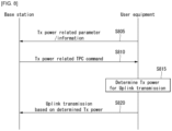
- FIG. 8 illustrates an example of a procedure for controlling uplink transmission power.
- a UE may receive parameters and/or information related to transmission (Tx) power from a BS S805.
- the UE may receive the corresponding parameters and/or information through higher layer signaling (for example, RRC signaling or MAC-CE).
- higher layer signaling for example, RRC signaling or MAC-CE.
- the UE may receive parameters and/or information related to the transmission power control (for example, Table 11 or Table 12).
- the UE may receive a TPC command related to the transmission power from the BS S810.
- the UE may receive the corresponding TPC command through lower layer signaling (for example, DCI).
- DCI lower layer signaling
- the UE may receive information on the TPC command to determine the power control adjustment state as described above through the TPC command field of a predefined DCI format.
- the corresponding step may be omitted.
- the UE may determine (or calculate) the transmission power for uplink transmission based on the parameter, information, and/or TPC command received from the BS S815. For example, the UE may determine the PUSCH transmission power, the PUCCH transmission power, the SRS transmission power, and/or the PRACH transmission power based on the method above (for example, Eq. 3 or Eq. 4). And/or when two or more uplink channels and/or signals need to be transmitted by being overlapped with each other as in the carrier aggregation situation, the UE may determine the transmission power for uplink transmission by considering the priority described in 5).
- the UE may perform transmission of one or more uplink channels and/or signals (for example, PUSCH, PUCCH, SRS, or PRACH) to the BS based on the determined (or calculated) transmission power S820.
- one or more uplink channels and/or signals for example, PUSCH, PUCCH, SRS, or PRACH
- the UE performs power headroom report to provide the following information to the BS.
- the UE configures two uplink carriers in a serving cell and determines Type 1 power headroom report and Type 3 power headroom report in the corresponding serving cell
- virtual PH in the present disclosure may mean Type 1 power headroom, Type 2 power headroom, and/or Type 3 power headroom determined based on reference transmission.
- the Type 1 power headroom (i.e., PH type1b,f,c ( i , j , q d ,l )) may be determined by Eq. 5.
- the Type 1 power headroom (i.e., PH type1b,f,c ( i , j , q d , l )) may be determined by Eq. 6.
- the Type 3 power headroom (i.e., PH type3b,f,c ( i , q s )) may be determined by Eq. 7.
- the Type 3 power headroom (i.e., PH type3b,f,c ( i , q s )) may be determined by Eq. 8.
- the BS uses PHR-Config to configure the UE to perform power headroom reporting, which is described in the TS 38.331 as shown in Table 13 below.
- Each field in Table 13 may be defined as follows.
- 'multiplePHR' Indicates if power headroom shall be reported using the Single Entry PHR MAC control element or Multiple Entry PHR MAC control element defined in TS 38.321 [3]. True means to use Multiple Entry PHR MAC control element and False means to use the Single Entry PHR MAC control element defined in TS 38.321 [3].
- the network configures this field to true for MR-DC and UL CA for NR, and to false in all other cases.
- 'phr-ModeOtherCG' Indicates the mode (i.e. real or virtual) used for the PHR of the activated cells that are part of the other Cell Group (i.e. MCG or SCG), when DC is configured. If the UE is configured with only one cell group (no DC), it ignores the field.
- 'phr-PeriodicTimer' Value in number of subframes for PHR reporting as specified in TS 38.321 [3]. Value sf10 corresponds to 10 subframes, value sf20 corresponds to 20 subframes, and so on.
- 'phr-ProhibitTimer' Value in number of subframes for PHR reporting as specified in TS 38.321 [3].
- Value sf0 corresponds to 0 subframe
- value sf10 corresponds to 10 subframes
- value sf20 corresponds to 20 subframes, and so on.
- 'phr-Tx-PowerFactorChange' Value in dB for PHR reporting as specified in TS 38.321 [3].
- Value dB1 corresponds to 1 dB
- dB3 corresponds to 3 dB and so on. The same value applies for each serving cell (although the associated functionality is performed independently for each cell).
- 'phr-Type2OtherCell' If set to true, the UE shall report a PHR type 2 for the SpCell of the other MAC entity. See TS 38.321 [3], clause 5.4.6. Network sets this field to false if the UE is not configured with an E-UTRA MAC entity.
- a power headroom report may be triggered if a specific event occurs as described in Table 14 below.
- a Power Headroom Report shall be triggered if any of the following events occur: - phr-ProhibitTimer expires or has expired and the path loss has changed more than phr-Tx- PowerFactorChange dB for at least one activated Serving Cell of any MAC entity which is used as a pathloss reference since the last transmission of a PHR in this MAC entity when the MAC entity has UL resources for new transmission;
- NOTE 1 The path loss variation for one cell assessed above is between the pathloss measured at present time on the current pathloss reference and the pathloss measured at the transmission time of the last transmission of PHR on the pathloss reference in use at that time, irrespective of whether the pathloss reference has changed in between.
- - phr-PeriodicTimer expires; - upon configuration or reconfiguration of the power headroom reporting functionality by upper layers, which is not used to disable the function; - activation of an SCell of any MAC entity with configured uplink; - addition of the PSCell (i.e.
- PSCell is newly added or changed); - phr-ProhibitTimer expires or has expired, when the MAC entity has UL resources for new transmission, and the following is true for any of the activated Serving Cells of any MAC entity with configured uplink: - there are UL resources allocated for transmission or there is a PUCCH transmission on this cell, and the required power backoff due to power management (as allowed by P-MPR c as specified in TS 38.101-1 [14], TS 38.101-2 [15], and TS 38.101-1 [16]) for this cell has changed more than phr-Tx-PowerFactorChange dB since the last transmission of a PHR when the MAC entity had UL resources allocated for transmission or PUCCH transmission on this cell.
- the MAC entity should avoid triggering a PHR when the required power backoff due to power management decreases only temporarily (e.g. for up to a few tens of milliseconds) and it should avoid reflecting such temporary decrease in the values of P CMAX,f,c /PH when a PHR is triggered by other triggering conditions.
- an uplink transmission resource for new transmission is allocated to the MAC entity of the UE, as described in Table P6.
- the UE may transmit the power headroom and/or PCMAX corresponding to the Type 1 PHR, Type 2 PHR, and/or Type 3 PHR to the BS by including the power headroom and/or the PCMAX in the MAC-CE.
- Table 15 Detailed conditions and steps related to the transmission are shown in Table 15.
- the MAC entity shall: 1> if it is the first UL resource allocated for a new transmission since the last MAC reset: 2> start phr-PeriodicTimer; 1> if the Power Headroom reporting procedure determines that at least one PHR has been triggered and not cancelled; and 1> if the allocated UL resources can accommodate the MAC CE for PHR which the MAC entity is configured to transmit, plus its subheader, as a result of LCP as defined in subclause 5.4.3,1: 2> if multiplePHR with value true is configured: 3> for each activated Serving Cell with configured uplink associated with any MAC entity: 4> obtain the value of the Type 1 or Type 3 power headroom for the corresponding uplink carrier as specified in subclause 7.7 of TS 38.213 [6); 4> if this MAC entity has UL resources allocated for transmission on this Serving Cell; or 4> if the other MAC entity, if configured, has UL resources allocated
- 3> instruct the Multiplexing and Assembly procedure to generate and transmit the Multiple Entry PHR MAC CE as defined in subclause 6.1.3.9 based on the physical values reported by the layer.
- the UE may transmit the value(s) for the Type 1/2/3 power headroom report (for example, power headroom(s) and/or PCMAX(s)) to the MAC layer from the Physical layer of the UE using the information preconfigured by the BS, and the MAC layer may deliver/report the value(s) (for example, power headroom(s) and/or PCMAX(s)) received (i.e., delivered) from the Physical layer as described in Tables 14 and 15 to the BS through the MAC-CE (for example, single Entry PHR MAC CE or Multiple Entry PHR MAC CE).
- the MAC CE for the corresponding power headroom report may be delivered/reported to the BS through the S920 step of FIG. 9 or transmitted/reported to the BS through uplink transmission performed subsequently.
- ' l ' may mean including (and) all of the content separated by / or include only a part of the separated content (or).
- the following terms are used uniformly for convenience of explanation
- Type II CSI feedback considers the 'DFT-based compression' method described in Table 16 as a method of combining beams (e.g., combining beams based on amplitude and/or phase) in a subband (SB)-wide width with respect to W 1 composed of L orthogonal DFT beams corresponding to wideband (WB) information.
- Table 16 shows an example of a DFT-based compression scheme from the viewpoint of reducing CSI reporting overhead based on the Type II CSI codebook of rank 1-2.
- a method of determining the number of non-zero (NZ) coefficients for each layer may be selected from the following examples (Alt 0/Alt1), in conjunction with the agreement that the maximum number of total non-zero (NZ) coefficients across all layers can be less than or equal to 2K 0 (where K 0 value (i.e., beta ⁇ ) is set for RI ⁇ 1,2 ⁇ .
- the parameter (y 0 , v 0 ) may be selected from 1 2 1 4 1 4 1 4 1 8 .
- [Table 17] RI Layer L p 1 0 x 0 y 0 2 0 1 3 0 v 0 1 2 4 0 1 2 3
- the above description refers to expressing channel information by using a basis such as DFT or a codebook for spatial domain (SD) and frequency domain (FD) information of CSI.
- the size of the reported total feedback is affected by the number of beams to be combined, the amount of quantization for combining coefficients, the size of a subband, etc., and in CSI feedback, most of the payload is generated when the UE reports information of w ⁇ 2 ⁇ to the base station.
- w ⁇ 2 ⁇ is composed of linear combination coefficients for the SD/FD codebook in the DFT-based compression scheme, and may be represented by a matrix of a size of 2LxM.
- the CSI component (or parameter) is divided into part 1 and part 2 so that it can be transmitted based on the feedback resource capacity allocated to the UCI, and by omitting channel state information according to a priority level within each part, it was possible to satisfy the requirement for the amount of UE CSI feedback resources.
- the enhanced Type II CSI codebook newly considered in NR is used in the frequency domain for the corresponding subbands. Therefore, since it is impossible to directly reuse the existing CSI omission operation, the CSI omission method needs to be newly considered according to the CSI codebook design.
- UCI constituting the Type II CSI reporting may include parameters as shown in Table 18.
- Table 18 shows examples of parameters constituting UCI part 1 and part 2.
- UCI part 1 may mean part 1 CSI
- UCI part 2 may mean part 2 CSI.
- K NZ,TOT the total number of non-zero coefficients summed across all the layers, where K NZ,TOT ⁇ ⁇ 1,2, ⁇ , 2K 0 ⁇ is reported in UCI part 1.
- the strongest coefficient indicator (SCI) is the log 2 K NZ -bit indicator.
- the sets c l i , m ⁇ i ⁇ c l i * , 0 and ⁇ k ⁇ m i ⁇ 0 ⁇ are reported.
- Informative note (for the purpose of reference procedure):
- the index ( l i ,m i ) of nonzero LC coefficients is remapped as l i m i ⁇ l i , m i ⁇ m i * mod M i .
- the codebook index associated with nonzero LC coefficient index ( l i , m i ) is remapped as k m i ⁇ k m i ⁇ k m i * mod N 3 .
- Combinatorial indicator for N 3 > 19 log 2 N 3 ′ ⁇ 1 M i ⁇ 1 -bit M initial Reported in UCI part 2 details on bitwidth and possible values are FFS
- the CSI omission may occur.
- the CSI omission may be expressed as UCI omission.
- the selected UCI omission scheme needs to satisfy the following criteria. i) CSI calculation is identical to the case without omission (identical). Otherwise, the UE will eventually recalculate the CSI when UCI omission occurs.
- the related CQI may not be conditionally calculated in PMI after the omission.
- the occurrence of the UCI omission may be inferred from related CSI reporting without additional signaling.
- a non-zero LC coefficient (NZC) associated with/related to the layer ⁇ ⁇ ⁇ 0,1,..., RI - 1 ⁇ , beam l ⁇ ⁇ 0,1,...,2 L - 1 ⁇ , and FD basis m ⁇ ⁇ 0,-1 ⁇ maybe represented by c l , m ⁇ .
- group 0 When the UE is configured to report the N Rep CSI reporting, group 0 includes at least SD rotation factors, SD indicator, and SCI(s) for all N Rep reports.
- group 1 may include at least a reference amplitude(s) for weaker polarization, c l , m ⁇ , ⁇ l m ⁇ G 1 , and an FD indicator.
- group 2 For each of the reports, group 2 includes at least c l , m ⁇ , ⁇ l m ⁇ G 2 .. Where G1 and G2 exclude indices related to the strongest coefficient(s).
- a priority rule for determining G1 and G2 may be selected from the following Alt1.1 to Alt 1.3:
- Alt 2.1 (only coupled with Alt 1.1), according to Prio( ⁇ ,l,m ), the first RI . 2 LM ⁇ K NZ TOT 2 bits belong to group 1, and according to a Prio( ⁇ ,l,m ) value, the last K NZ TOT 2 bits belong to group 2.
- Each segment includes the bitmap (sub-bitmap) associated with/related to all RI layers, bitmap (sub-bitmap) associated with/related to all the SD components and a single FD component, and corresponding combining coefficients.
- a payload size of group 2 is given by K NZ TOT 2 a + b .
- Alt 2.3 (only coupled with Alt 1.3), according to a Prio ( ⁇ ,l,m ) value, the first RI 2 LM ⁇ K NZ TOT / 4 L ⁇ 2 L bits belong to group 1, and according to the Prio( ⁇ , l , m ) value, the last K NZ TOT / 4 L ⁇ 2 L bits belong to group 2.
- Alt 2.4 (only coupled with Alt 1.1), according to the Prio( ⁇ ,l,m ) value, the first RI.LM bits belong to group 1, and according to the Prio( ⁇ ,l,m ) value, the last RI.LM belongs to group 2.
- the CSI reporting through the PUSCH may be composed of UCI part1 and UCI part2.
- the UCI part1 includes the number of amplitude coefficients ( K NZ ) of RI and non-zero wideband (WB), and the UCI part2 includes information on PMI of wideband (WB)/subband (SB).
- a parameter (component) included in the UCI part1 may be a parameter (component) of part1 CSI
- a parameter (component) included in the UCI part2 may be a parameter (component) of part2 CSI.
- the payload of the UCI part1 is fixed, while the payload of the UCI part2 has a variable amount (size) according to RI and K NZ .
- the base station needs to first decode the UCI part1 to calculate RI and K NZ information. Therefore, UCI omission may have to be performed in the UCI part2.
- the UCI omission may be replaced/used interchangeably with CSI omission.
- the precoding matrix indicator (PMI) payload for Type II CSI feedback varies greatly depending on the RI
- PMI precoding matrix indicator
- the RI is set by the UE, in terms of the base station, there may be limitations in scheduling resource allocation by accurately predicting the PMI payload for CSI reporting.
- a method of dropping a plurality of reporting settings for a plurality of component carriers (CC) of part2 CSI according to a predetermined priority rule is used in a CSI omission procedure.
- the base station may calculate the corresponding information by estimating the remaining omitted subband (SB) PMI in an interpolation method based on the received PMI.
- SB subband
- the base station performs the same CSI omission process as the UE until the UCI code rate reaches a specific level. Therefore, only when a common method for the CSI omission is set/defined between the UE and the base station, the information of the UCI part 2 may be properly decoded by the base station.
- the enhanced Type II CSI codebook may be designed in consideration of frequency domain (FD) compression for a plurality of subband (SB) CSI by utilizing a basis such as DFT. That is, the radio channel information may be expressed by approximating information W ⁇ 2 on a linear combination of the SD basis (W1) and the FD basis (Wf) predetermined or set by the UE and the base station, and the UE may perform the CSI reporting by transmitting configuration information for the codebook and W ⁇ 2 .
- FD frequency domain
- Wf FD basis
- complex-valued LC coefficients as many as 2LxM are different from the existing PMI for each SB. That is, since the base station cannot know the distribution according to the SD basis, the FD basis, and the layer of the corresponding LC coefficients before decoding the UCI part2 information, the above problem cannot be solved through the reuse of the conventional CSI omission rules/methods.
- the base station and the UE promise an omission method for LC coefficients and a corresponding bitmap based on the enhanced Type II codebook design
- the base station sequentially applies the omission until the UCI code rate reaches a specific threshold code rate, and thus, it is possible to estimate the CSI omission level performed by the UE. Therefore, the present disclosure intends to propose a CSI omission(omission) (in UCI part2) method in the enhanced Type II CSI codebook.
- the Type II CSI codebook (including the enhanced Type II CSI codebook) includes an SD basis-related matrix, an FD basis-related matrix, and a matrix of LC coefficients.
- the matrix of LC coefficients may include amplitude coefficients and phase coefficients.
- the codebook may be replaced with terms such as precoder or precoding matrix, and the basis may be replaced with terms such as a basis vector, a vector, and a component.
- the spatial domain will be expressed as SD and the frequency domain will be expressed as FD.
- W ⁇ 2 may be expressed as a matrix with a size of 2L ⁇ M.
- 2L denotes the number of SD bases (here, L is the number of beam/antenna ports in SD, taking polarization into consideration, the total number of SD bases may be 2L), and M denotes the number of FD bases.
- L the number of beam/antenna ports in SD, taking polarization into consideration, the total number of SD bases may be 2L
- M denotes the number of FD bases.
- the UE When the UE receives the Type II CSI set as PUSCH-based reporting and the CSI payload is greater than the allocated resource capacity, for UCI part 2 (i.e., part 2 CSI) information configuration, it is possible to set/define an omission element and an omission method in a pre-defined manner.
- UCI part 2 i.e., part 2 CSI
- the UE when the UE wants to report CSI to the base station, if the corresponding PUSCH resource capacity does not satisfy the CSI payload, some or all of the UCI part 2 components of the CSI are dropped to allow the UE to transmit the channel information to the base station within the available resource capacity range. In addition, whether the UE configures UCI by performing the CSI omission may be indicated to the base station.
- the UCI part 2 may include information such as a bitmap per layer, an SD/FD basis indicator, LC coefficients per layer (amplitude/phase), and SCI per layer (the strongest coefficient indicator).
- the information on the LC coefficients may include an indicator indicating amplitude coefficients and an indicator indicating phase coefficients.
- the bitmap information for each layer may be bitmap information for indicating an indicator indicating reported amplitude coefficients and an indicator indicating phase coefficients.
- the information on the LC coefficients (amplitude coefficient/phase coefficient) and the bitmap information corresponding thereto may have the greatest influence on the payload size among the components. Therefore, it is necessary to specify an omission method for these parameters (components) (e.g., amplitude coefficient, phase coefficient, bitmap, etc.), and the omission method can be configured by utilizing SCI for each layer.
- the base station may not know its value before decoding UCI part 2 based on UCI part 1 information.
- FIG. 9 is an example of index remapping of W ⁇ 2 based on SCI.
- FIG. 9A illustrates the SCI index in W ⁇ 2
- FIG. 9B illustrates the SCI index after the index remapping.
- FIG. 9 is only an example for convenience of description, and does not limit the technical scope of the present disclosure.
- a matrix W ⁇ 2 composed of LC coefficients has a size of ⁇ 2L ⁇ M ⁇ .
- the LC matrix W ⁇ 2 may be configured in an 8 ⁇ 10 matrix. As illustrated in FIG.
- the LC coefficients corresponding from the FD basis and SD basis corresponding to SCI may have a greater effect on CSI accuracy compared to other LC coefficients. Based on this, it is possible to configure omission priority by differentiating the drop degree of specific components in UCI omission.
- the base station may also be adjusted to the code rate to which the omission is applied, so the UCI part 2 may be properly decoded. Therefore, it is possible for the listed bitmap and LC coefficients to indicate the correct value for W ⁇ 2 through the decoded SCI.
- Proposal 1-1 We propose a method of setting an omission element (e.g., bitmap, LC coefficients, etc.) and an omission scheme in the frequency domain for UCI part 2 information configuration of Type II CSI.
- an omission element e.g., bitmap, LC coefficients, etc.
- a case in which it is assumed that the number of components (or basis) of the frequency domain FD is M, selects and reports M' components among them, and omits the rest may be considered.
- FD frequency domain
- FIG. 10 illustrates an example of setting three levels of omission priority in terms of the FD together with a pair of SD bases.
- the priority level for the SD index may also be configurable.
- FIG. 10 is only an example for convenience of description, and does not limit the technical scope of the present disclosure.
- UCI omission for one of the two groups may be performed by dividing linear combination coefficients (LCCs) to be transmitted and LC coefficients to be dropped into two groups (e.g., G1 and G2). in a situation in which UCI omission is performed.
- UCI omission for one of the two groups may be performed by dividing it into two groups (e.g., G1 and G2). For example, one group may be dropped/omitted according to the priority of the group.
- a priority level for determining which group a specific LC coefficient belongs to may be expressed as in Equation 9.
- the priority level may also be expressed as a priority value.
- Equation 3 may assume that LC coefficients are prioritized in the order of i) layer, ii) SD index, and iii) FD index. Also, Perm1() and Perm2() indicate permutation schemes for FD and SD indices, respectively. The lower/smaller the Prio() (i.e., priority level) in Equation 3, the higher the priority of the corresponding LC coefficient.
- K NZ TOT 2 LC coefficients with high priority are included in the group with high priority (e.g., G1) and the remaining K NZ TOT 2 LC coefficients are included in the group with low priority (e.g., G2).
- K NZ TOT is the total number of non-zero LC coefficients of W ⁇ 2 .
- a group having a lower priority may be omitted first.
- G2 including LC coefficients with low priority may be omitted earlier than G1. In other words, LC coefficients with high priority are reported, and LC coefficients with low priority may be omitted.
- Equation 9 and related descriptions may also be referenced/used in an omission operation in a spatial region, which will be described later.
- a column corresponding to SCI is located a 0th column through a modulo (modulus) operation.
- How the SCI information can be reflected in the priority level (or priority value) Equation may be dealt with. That is, a method of performing CSI omission based on SCI for each layer may be considered.
- the permutation of the FD index may be performed based on the following methods 1)/ 2)/ 3), and the UCI omission may be performed by calculating a priority level in the frequency domain (FD).
- FIG. 11 illustrates an example of a delay profile of a radio channel.
- FIG. 11 is only an example for convenience of description, and does not limit the technical scope of the present disclosure.
- the basis index may be alternately selected based on the index 0. For example, +1, -1, +2, -2,.. may be selected by crossing with respect to 0. Alternatively, the selection may be alternately selected based on 0, such as -1, +1, -2, +2,.. Alternatively, the basis index may be selected alternately (intersectingly) with a circular shift.
- the index may be remapped, i.e., permutated, such as [0,7,1,6,2,5,3,4], so the priority value may be determined.
- the LC coefficients corresponding to the FD index of [0,7,1,6] may be included in the group (e.g., G1) with high priority, and the LC coefficients corresponding to [2,5,3,4] may be included in the group (e.g., G2) with low priority.
- A denotes Perm1()
- x denotes an FD index
- b denotes a permutation applied FD index.
- the omission method considering the delay profile described above is excellent in terms of performance, it may be necessary to include a 1-bit indication of the delay profile shape in UCI part 2 group 0. In other words, it is necessary to indicate/set which delay profile the UE follows (e.g., either of FIG. 11A or 11B ) using a 1-bit indication.
- the ascending permutation scheme may be configured including -1 or -2 FD basis. For example, it may be expressed in the order of [0, 7, 1, 2, 3, 4, 5, 6] according to an ascending permutation scheme including -1st FD basis. For example, it may be expressed in the order of [0, 7, 6, 1, 2, 3, 4, 5] according to an ascending permutation scheme including -2nd FD basis. That is, at least one of the -1st or -2nd FD bases may be positioned between permutation schemes arranged in ascending order.
- the -1 or -2nd FD basis may be configured as a starting point.
- the UCI omission may be performed according to a method predefined between the base station and the terminal.
- the base station may set a permutation scheme to the UE.
- the UE may report a permutation scheme applied to UCI omission to the base station together with CSI reporting.
- a priority level for the LC coefficients may be calculated, and the LC coefficients may be divided into a plurality of groups based on the priorities of the LC coefficients.
- the LC coefficients of the lower group may be omitted according to the priority of the group. That is, the omission may be performed according to the priority of the LC coefficient and reported to the base station.
- Proposal 1-2 We propose a method of setting an omission element (e.g., bitmap, LC coefficients, etc.) and an omission scheme in the spatial domain for the UCI part 2 information configuration of Type II CSI.
- an omission element e.g., bitmap, LC coefficients, etc.
- a spatial domain (SD) aspect in a manner similar to that of Proposal 1-1, it may be set in a manner such as reporting the LC coefficients belonging to two rows by utilizing the SD basis corresponding to SCI and the SD basis being a pair in terms of the antenna port, and the bitmap size may be set as many as the number.
- it can be used to operate by using ⁇ M' SD bases based on a specific SD basis or to report LC coefficients belonging to a row of W ⁇ 2 set through a specific rule.
- FIG. 12 illustrates an example of setting omission priority in SD aspect with a single FD base.
- a case of reporting a pair SD base may be set as priority 0
- a case of reporting a single SD base may be set as a priority of 1, and the priority level may be set.
- SD bases i.e., single SD bases
- corresponding to priority 1 may be reported.
- a method of performing permutation in consideration of SCI in a permutation scheme in terms of SD may be considered. It may be said that the influence of the SD beam corresponding to the value indicated by the SCI is most conspicuously reflected in the spatial domain SD of the proposal 1-2. Therefore, a permutation scheme such as 1)/2)/3) below may be considered.
- SCI_pair shares the same SD beam as SCI, it is highly likely that it includes many LC coefficients that affect CSI accuracy. Therefore, if the row corresponding to SCI and the row corresponding to SCI_pair are mapped to the 0th and 1st indexes and given a priority level, it may be effective in reducing the loss of CSI accuracy while performing the UCI omission.
- the UCI omission may be performed according to a method predefined between the base station and the terminal.
- the base station may configure the permutation method to the UE.
- the UE may report a permutation method applied to UCI omission to the base station together with CSI reporting.
- the omission in the FD aspect of Proposal 1-1 and the omission in the SD aspect of Proposal 1-2 may operate independently or in the form of an intersection, and the configuration according to this will be possible with higher layer configured or pre-defined.
- the permutation scheme in FD may be performed by one of the methods described in Proposal 1-1
- the permutation scheme in SD may be performed by one of the methods described in Proposal 1-2
- the priority level may be calculated by considering both permutations in SD and SD.
- a method of alternately selecting a basis index based on index 0 e.g., alternate selection based on example 0, such as +1, -1, +2, -2,...) may be applied
- the permutation scheme in SD a method of selecting an index in ascending order based on the 0th row may be applied.
- the UE may perform CSI omission in consideration of the calculated priority step, and may configure UCI to satisfy the resource size allocated for CSI reporting and transmit the UCI to the base station.
- the UE may perform a UCI omission operation, and the UE may consider a method of setting the components of UCI part 2 information and the omission method through information (e.g., indicator) related to UCI omission.
- information e.g., indicator
- the presence or absence of UCI omission may be set through a higher layer or set/transmitted to the base station according to a predefined rule.
- proposal 2 may increase the payload of UCI part 1 compared to proposal 1, it has the advantage that the UE and the base station may promise detailed operations for the CSI omission and accurately recognize the CSI omission.
- the LC coefficients are configured for amplitude and phase, respectively, and one of them may indicate drop/omission.
- configuring the UCI part 2 by adjusting the amplitude of the LC coefficients and the quantization degree of the phase may also have a great effect in terms of payload reduction.
- Table 20 shows an example of Type II CSI omission operation according to the UCI omission indicator in the case of layer-common.
- Indicator (2bits) LC coefficients Omission priority Degree of quantization Amp. Phase FD SD Amp. Phase '00' Default Default Default Default Default Default Default '01' O X 2 1 QPSK - '10' X O 1 1 - 8-PSK '11' O O 0 0 16-PSK 16-PSK
- the UE may transmit/configure information, such as omission state of the LC coefficients (e.g., amplitude coefficient and phase coefficient), omission priority for the frequency domain and spatial domain, quantization degree, to the base station through information (e.g., indicator) related to UCI omission.
- information e.g., indicator
- the base station may clearly recognize the UCI omission operation of the UE based on the information related to the UCI omission.
- the UE may perform the UCI omission within the allocated resource capacity and report the channel state information to the base station.
- FIG. 13 illustrates an example of a signaling flowchart between a user equipment (UE) and a base station to which the method and/or embodiment proposed in the present disclosure can be applied.
- FIG. 13 is only for convenience of description, and does not limit the scope of the present disclosure. Referring to FIG. 13 , it is assumed that the UE and/or the base station operate based on the methods and/or embodiments of the above-described proposals 1 and 2. Some of the steps described in FIG. 13 may be merged or omitted. In addition, in performing the procedures described below, the CSI-related operation of FIG. 7 may be considered/applied.
- the base station may refer to an object that transmits and receives data to and from the UE.
- the base station may be a concept including one or more transmission points (TPs), one or more transmission and reception points (TRPs), and the like.
- the TP and/or TRP may include a panel of a base station, a transmission and reception unit, and the like.
- the TRP may be classified according to information (e.g., index, ID) on the CORESET group (or CORESET pool).
- information e.g., index, ID
- the CORESET group or CORESET pool
- the setting for such a CORESET group (or CORESET pool) may be performed through higher layer signaling (e.g., RRC signaling, etc.).
- the UE may receive configuration information from the BS S1310.
- the BS may transmit the configuration information to the UE.
- the configuration information may be received through higher layer signaling (for example, radio resource control (RRC) or medium access control-control element (MAC-CE)).
- RRC radio resource control
- MAC-CE medium access control-control element
- the configuration information may include (i) CSI related configuration and (ii) configuration related to transmission power control of an uplink channel (for example, PUSCH/PUCCH).
- the corresponding step may be omitted when the configuration information is preconfigured.
- the configuration related to transmission power control of the uplink channel may include configuration related to path loss, maximum output power, and target power as described above concerning the uplink power control.
- the CSI related configuration may include information on the period at which a reference signal is transmitted and time domain behavior information of the reference signal.
- the CSI related configuration may include information on a resource and/or a resource set to which the reference signal is transmitted.
- the CSI related configuration may include information on the CSI reporting setting. For example, whether CSI reporting is PUSCH-based CSI reporting or PUCCH-based CSI reporting may be configured based on the CSI related configuration. Also, the CSI related configuration may include resource allocation information for CSI reporting.
- the CSI related configuration may include information related to the CSI omission operation of the UE.
- the CSI related configuration may include information used to determine the priority of CSI (for example, a permutation method).
- the UE may receive a reference signal (RS) from the BS S1320.
- the BS may transmit a reference signal to the UE.
- the reference signal may be received or transmitted based on the configuration information (for example, CSI related configuration).
- the reference signal may be a CSI-RS.
- the reference signal may be transmitted periodically, semi-continuously, or aperiodically from the BS. Also, the reference signal may be used for CSI measurement and calculation.
- the UE may measure/calculate CSI (S1325).
- the CSI may be measured/calculated based on the (enhanced) Type II CSI codebook, and may include information on a precoding matrix (e.g., PMI, etc.).
- a precoding matrix based on a linear combination of a basis in a frequency domain and a basis in a spatial domain may be used for CSI calculation.
- the row index of the precoding matrix may be related to a basis of a spatial domain
- a column index of the matrix may be related to a basis of a frequency domain.
- a column index of the strongest coefficient indicator (SCI) may correspond to '0'.
- the CSI includes information for coefficients related to linear coupling coefficients (e.g., amplitude coefficient, phase coefficient, etc.), for example, information on amplitude coefficient, information on phase coefficient, information on the bitmap form related to the coefficients (amplitude coefficient and phase coefficient), information on the strongest coefficient for each layer, information on the basis of the spatial domain, information on the basis of the frequency domain, and the like.
- coefficients related to linear coupling coefficients e.g., amplitude coefficient, phase coefficient, etc.
- the UE may transmit CSI to the BS S1330.
- the BS may receive CSI from the UE.
- the CSI may be transmitted through PUSCH or PUCCH.
- the transmission power of PUSCH or PUCCH may be determined based on configuration information.
- the operation of determining transmission power may consult or apply the operation of FIG. 8 and the description related thereto.
- the CSI report transmitted to the BS may consist of a first part and a second part.
- the first part may correspond to the uplink control information (UCI) part 1 (i.e., part 1 CSI)
- the second part may correspond to the UCI part 2 (i.e., part 2 CSI).
- UCI uplink control information
- a resource for CSI reporting may be allocated based on the configuration information, and if the capacity of an allocated resource is smaller than the UCI payload (i.e., CSI payload to report) size, the CSI report may be configured by omitting a portion of the calculated CSI so that the CSI reporting may be performed within the available range of resource capacity. For example, based on the priorities of a plurality of predefined groups, uplink control information (UCI) configured by omitting a portion of the plurality of groups may be transmitted as a CSI report through PUSCH. For example, some of the components constituting the second part of the CSI report (i.e., UCI part 2) may be omitted. The operation related to the CSI omission may be performed based on the proposed method (for example, Proposal 1/Proposal 2).
- UCI uplink control information
- each of the information on the amplitude coefficient, the information on the phase coefficient, and the bitmap information related to the coefficients may be classified into a plurality of groups based on a priority value.
- the priority value and the priority of each information component may be inversely proportional to each other. That is, as the priority value is smaller, the priority of the corresponding component may be higher.
- a component having a higher priority among components of information on amplitude coefficients, information on phase coefficients, and bitmap information related to the coefficients may be included in the first group, and the group with low priority may be included in the second group.
- a group having a lower priority may be omitted first.
- the first group may have a higher priority than the second group.
- the second group may be omitted earlier than the first group.
- the information on amplitude coefficients, the information on phase coefficients, and the bitmap information with high priority may be reported, and the omission (omission) may be performed from information with low priority.
- the priority value used to classify the information on the amplitude coefficient, the information on the phase coefficient, and/or the components of the bitmap information related to the coefficients into a plurality of groups may be determined based on at least one of i) layer index, ii) the index of the spatial area associated with/related to each component, or iii) the index of the frequency domain associated with/related to each component.
- the priority value may be determined based on i) a layer index ii) an index of a spatial domain associated with/related to each component, and iii) an index of a frequency domain associated with/related to each component.
- the priority value may increase in an order in which a higher index and a lower index of the indexes of the frequency domain associated with/related to the components are sequentially crossed based on a predefined specific index.
- the predefined specific index may be associated with/related to an index in the frequency domain of a strongest coefficient among the coefficients.
- the priority value may increase in an ascending order of the index of the spatial region.
- i) the index of the spatial region of the strongest coefficient and ii) the index of the spatial region corresponding to the beam having the opposite polarization with respect to the beam corresponding to the strongest coefficient may have the highest priority (i.e., the priority value may be the smallest).
- the priority values of the remaining indexes may be sequentially determined in ascending order.
- the indexes are remapped so that the index of the spatial region of the strongest coefficient becomes 0, and the remaining indexes are also remapped in the form of a cyclic shift, and then priority values may be determined in the order of the remapped indexes.
- the bases (or components) (e.g., M) of the frequency domain are reported (e.g., M') and the remaining parts are omission
- it is possible to select the consecutive indexes as many as the bases to be reported based on based on the index (e.g., index 0) in the frequency domain of the strongest coefficient, and report the information on the corresponding coefficients and the information in the form of a bitmap corresponding to the coefficients.
- the index corresponding to the index in the spatial domain of the strongest coefficient and the coefficients corresponding to the indexes of the SD bases that is a pair in terms of the antenna port and the information in the form of the bitmap corresponding to the coefficients may be reported (coefficients corresponding to the remaining SD base indexes and the information in the form of the bitmap corresponding thereto may be omitted).
- the CSI reporting may further include information indicating a delay profile applied by the UE or information used by the UE to determine a priority for CSI omission (e.g., a permutation scheme).
- the CSI reporting(or UCI) may further include information related to the CSI omission operation.
- the UE may explicitly transmit information related to the CSI omission operation to the base station.
- the CSI reporting since the CSI reporting may be configured by omission of a specific group according to the priority of a plurality of groups, it may include information related to the omission of a specific group to be omitted.
- the information related to the CSI omission operation may be transmitted while being included in the first part of the CSI reporting.
- the information related to the CSI omission operation may include information on at least one of i) presence and absence of omission operation (i.e., whether the UE has performed omission), ii) omission target, or iii) omission.
- the UE may transmit/configure information, such as omission state of the coefficients, omission priority for the frequency domain and spatial domain, quantization degree, to the base station through information (e.g., indicator) related to the CI omission.
- the base station may clearly recognize the CSI omission operation of the UE based on the information related to the CSI omission.
- FIG. 14 illustrates an example of an operation flowchart of a UE to which the method and/or embodiment proposed in the present disclosure may be applied.
- the UE and/or the base station operate based on the methods and/or embodiments of the above-described proposals 1 and 2. Some of the steps described in FIG. 14 may be merged or omitted. In addition, in performing the procedures described below, the CSI-related operation of FIG. 7 may be considered/applied.
- the UE receives configuration information from the BS S1410.
- the configuration information may be received through higher layer signaling (for example, radio resource control (RRC) or medium access control-control element (MAC-CE)).
- RRC radio resource control
- MAC-CE medium access control-control element
- the configuration information includes (i) CSI related configuration and (ii) configuration related to transmission power control of an uplink channel (for example, PUSCH/PUCCH).
- the configuration related to transmission power control of the uplink channel may include configuration related to path loss, maximum output power, and target power as described above concerning the uplink power control.
- the CSI related configuration may include information on the period at which a reference signal is transmitted and time domain behavior information of the reference signal.
- the CSI related configuration may include information on a resource and/or a resource set to which the reference signal is transmitted.
- the CSI related configuration may include information on the CSI reporting setting. For example, whether CSI reporting is PUSCH-based CSI reporting or PUCCH-based CSI reporting may be configured based on the CSI related configuration.
- the CSI related configuration may include resource allocation information for CSI reporting.
- the CSI related configuration may include information related to the CSI omission operation of the UE.
- the CSI related configuration may include information used to determine the priority of CSI (for example, a permutation method).
- the operation of receiving configuration information by the UE (100/200 of FIGS. 16 to 20 ) in the S1410 step from the BS (100/200 of FIGS. 16 to 20 ) may be implemented by the devices of FIGS. 16 to 20 to be described later.
- one or more processors 202 may control one or more transceivers 206 and/or one or more memories 204 to receive the configuration information.
- one or more transceivers 206 may receive the configuration information from the BS.
- the UE receives a CSI-Reference Signal (CSI-RS) from the BS S1420.
- CSI-RS CSI-Reference Signal
- the CSI-RS is received based on the CSI related configuration.
- the CSI-RS may be transmitted periodically, semi-continuously, or aperiodically from the BS.
- the CSI-RS may be used for CSI measurement and calculation.
- the operation of receiving a CSI-RS by the UE (100/200 of FIGS. 16 to 20 ) in the S1420 step from the BS (100/200 of FIGS. 16 to 20 ) may be implemented by the devices of FIGS. 16 to 20 to be described later.
- one or more processors 202 may control one or more transceivers 206 and/or one or more memories 204 to receive the CSI-RS.
- one or more transceivers 206 may receive the CSI-RS from the BS.
- the UE measures/calculates CSI (S1430).
- the CSI may be measured/calculated based on the (enhanced) Type II CSI codebook, and may include information on a precoding matrix (e.g., PMI, etc.).
- a precoding matrix e.g., PMI, etc.
- the CSI includes information related with coefficients.
- the information related to the coefficients may include at least one of i) information on the amplitude coefficient, ii) information on the phase coefficient, or iii) bitmap information related to the amplitude coefficient and the phase coefficient.
- step S1430 the operation of measuring/calculating the CSI by the UE (100/200 in FIGS. 16 to 20 ) in step S1430 described above may be implemented by the device in FIGS. 16 to 20 to be described below.
- one or more processors 202 may control one or more transceivers 206 and/or one or more memories 204 to measure/calculate the CSI.
- the UE transmits, to the BS, a CSI report configured by omitting a portion of the plurality of groups based on a pre-defined priority of the plurality of groups, through the Physical Uplink Shared Channel (PUSCH) S1340.
- the transmission power of the PUSCH is determined based on the configuration information.
- the CSI report may include a first part and a second part.
- the first part may correspond to the uplink control information (UCI) part 1 (i.e., part 1 CSI)
- the second part may correspond to the UCI part 2 (i.e., part 2 CSI).
- a portion of the second part of the CSI report may be omitted. Omission of the second part of the CSI report may be performed based on the proposed methods (for example, Proposal 1/Proposal 2).
- the constituting elements of the information related to the coefficients for example, information on the amplitude coefficient, information on the phase coefficient, and bitmap information related to the amplitude coefficient and the phase coefficient
- the CSI report namely, UCI is configured by omitting a specific group according to the priority of the plurality of groups.
- a group with a low priority may be omitted first.
- a specific group to be included in the second part of the CSI report may be omitted.
- the priority of each component may be higher.
- an element with high priority among elements of the information related to the coefficients may be included in the first group, and an element with low priority may be included in the second group.
- the priority of the first group is higher than that of the second group, and thus, the second group may be omitted before the first group.
- the priority value is determined based on at least one of i) a layer index ii) an index of a spatial domain associated with/related to each component or iii) an index of a frequency domain associated with/related to each component.
- the priority value may be determined based on i) a layer index ii) an index of a spatial domain associated with/related to each component, and iii) an index of a frequency domain associated with/related to each component.
- the priority value may increase in an order in which a higher index and a lower index of the indexes of the frequency domain associated with/related to the components are sequentially crossed based on a predefined specific index.
- the predefined specific index may be associated with/related to an index in the frequency domain of a strongest coefficient among the coefficients.
- the predefined specific index may be '0'.
- the priority value may increase in an ascending order of the index of the spatial region.
- i) the index of the spatial region of the strongest coefficient and ii) the index of the spatial region corresponding to the beam having the opposite polarization with respect to the beam corresponding to the strongest coefficient may have the highest priority (i.e., the priority value may be the smallest).
- the priority values of the remaining indexes may be sequentially determined in ascending order.
- the indexes are remapped so that the index of the spatial region of the strongest coefficient becomes 0, and the remaining indexes are also remapped in the form of a cyclic shift, and then priority values may be determined in the order of the remapped indexes.
- the bases (or components) (e.g., M) of the frequency domain are reported (e.g., M') and the remaining parts are omission
- it is possible to select the consecutive indexes as many as the bases to be reported based on based on the index (e.g., index 0) in the frequency domain of the strongest coefficient, and report the information on the corresponding coefficients and the information in the form of a bitmap corresponding to the coefficients.
- the index corresponding to the index in the spatial domain of the strongest coefficient and the coefficients corresponding to the indexes of the SD bases that is a pair in terms of the antenna port and the information in the form of the bitmap corresponding to the coefficients may be reported (coefficients corresponding to the remaining SD base indexes and the information in the form of the bitmap corresponding thereto may be omitted).
- the CSI reporting may further include information related to the CSI omission.
- the CSI reporting(or UCI) since it may be configured by omission of a specific group according to the priority of a plurality of groups, it may include information related to the omission of a specific group to be omitted.
- the information related to the omission of the specific group may include information on at least one of i) presence and absence of omission (i.e., whether the UE has performed omission), ii) omission target, or iii) omission degree.
- the information (i.e., information related to omission of a specific group) related to the CSI omission may be transmitted while being included in the first part of the CSI reporting.
- the operation of transmitting UCI by the UE (100/200 of FIGS. 16 to 20 ) in the S1440 step to the BS (100/200 of FIGS. 16 to 20 ) through PUSCH may be implemented by the devices of FIGS. 16 to 20 to be described later.
- one or more processors 202 may control one or more transceivers 206 and/or one or more memories 204 to transmit UCI through PUSCH.
- one or more transceivers 206 may transmit UCI to the BS through PUSCH.
- FIG. 15 illustrates an example of an operation flowchart of the base station to which the method and/or embodiment proposed in the present disclosure may be applied.
- FIG. 15 is only for convenience of description, and does not limit the scope of the present disclosure. Referring to FIG. 15 , it is assumed that the UE and/or the base station operate based on the methods and/or embodiments of the above-described proposals 1 and 2. Some of the steps described in FIG. 15 may be merged or omitted. In addition, in performing the procedures described below, the CSI-related operation of FIG. 7 may be considered/applied.
- the BS may collectively mean an object that performs data transmission/reception with the UE.
- the BS may include one or more TPs (Transmission Points), one or more TRPs (Transmission and Reception Points), and the like.
- the TP and/or TRP may include a panel, a transmission and reception unit, and the like of the BS.
- the TRP may be distinguished according to information (e.g., index or ID) for a CORESET group (or CORESET pool).
- information e.g., index or ID
- a CORESET group or CORESET pool
- a configuration for the CORESET group (or CORESET pool) may be performed through higher layer signaling (e.g., RRC signaling).
- the BS may transmit configuration information to the UE S1510.
- the configuration information may be transmitted through higher layer signaling (for example, RRC or MAC-CE).
- the configuration information may include (i) CSI related configuration and (ii) configuration related to transmission power control of an uplink channel (for example, PUSCH/PUCCH).
- an uplink channel for example, PUSCH/PUCCH.
- the CSI related configuration may include configuration information on a reference signal for CSI and resource allocation information for CSI reporting.
- the configuration information related to the reference signal may include information on the period at which the reference signal is transmitted and time domain behavior information of the reference signal.
- the configuration information related to the reference signal may include information on a resource and/or a resource set to which the reference signal is transmitted.
- the CSI related configuration may include information on the CSI reporting setting. For example, whether CSI reporting is PUSCH-based CSI reporting or PUCCH-based CSI reporting may be configured based on the information on the CSI reporting setting.
- the CSI related configuration may include information related to the CSI omission (or UCI omission) operation of the UE.
- the CSI related configuration may include information used to determine the priority of CSI (for example, a permutation method).
- the operation of transmitting configuration information by the BS (100/200 of FIGS. 16 to 20 ) in the S1510 step to the UE (100/200 of FIGS. 16 to 20 ) may be implemented by the devices of FIGS. 16 to 20 to be described later.
- one or more processors 202 may control one or more transceivers 206 and/or one or more memories 204 to transmit the configuration information.
- one or more transceivers 206 may transmit the configuration information to the UE.
- the BS may transmit a CSI-RS to the UE S1520.
- the CSI-RS may be transmitted based on the CSI related configuration.
- the CSI-RS may be transmitted periodically, semi-continuously, or aperiodically.
- the CSI-RS may be used for CSI measurement and calculation by the UE.
- the operation of transmitting a CSI-RS by the BS (100/200 of FIGS. 16 to 20 ) in the S1510 step to the UE (100/200 of FIGS. 16 to 20 ) may be implemented by the devices of FIGS. 16 to 20 to be described later.
- one or more processors 202 may control one or more transceivers 206 and/or one or more memories 204 to transmit the CSI-RS.
- one or more transceivers 206 may transmit the CSI-RS to the UE.
- the CSI may be measured/calculated based on the (enhanced) Type II CSI codebook, and may include information on a precoding matrix (e.g., PMI, etc.).
- the CSI may include information related with coefficients.
- the information related to the coefficients may include at least one of i) information on the amplitude coefficient, ii) information on the phase coefficient, or iii) bitmap information related to the amplitude coefficient and the phase coefficient.
- the CSI may be measured/calculated based on the (improved) Type II CSI codebook and may include information on the precoding matrix (for example, PMI).
- the CSI may include information related with coefficients.
- the information related with coefficients may include at least one of i) information on the amplitude coefficient, ii) information on the phase coefficient, or iii) bitmap information related to the amplitude coefficient and the phase coefficient.
- the priority value may be determined based on at least one of i) a layer index ii) an index of a spatial domain associated with/related to each component or iii) an index of a frequency domain associated with/related to each component.
- the priority value may be determined based on i) a layer index ii) an index of a spatial domain associated with/related to each component, and iii) an index of a frequency domain associated with/related to each component.
- the priority value may increase in an order in which a higher index and a lower index of the indexes of the frequency domain associated with/related to the components are sequentially crossed based on a predefined specific index.
- the predefined specific index may be associated with/related to an index in the frequency domain of a strongest coefficient among the coefficients.
- the predefined specific index may be '0'.
- the priority value may increase in an ascending order of the index of the spatial region.
- the priority value may increase in an order in which a higher index and a lower index of the indexes of the frequency domain associated with/related to the components are sequentially crossed based on a predefined specific index.
- the predefined specific index may be associated with/related to an index in the frequency domain of a strongest coefficient among the coefficients.
- the predefined specific index may be '0'.
- the priority value may increase in an ascending order of the index of the spatial region.
- the operation of receiving UCI including CSI by the BS (100/200 of FIGS. 16 to 20 ) in the S1530 step from the UE (100/200 of FIGS. 16 to 20 ) through PUSCH may be implemented by the devices of FIGS. 16 to 20 to be described later.
- one or more processors 202 may control one or more transceivers 206 and/or one or more memories 204 to receive UCI including CSI through PUSCH.
- one or more transceivers 206 may receive UCI including CSI from the UE through PUSCH.
- the UE and/or the base station operating according to each step of the above-described methods and embodiments may be specifically implemented by the device in FIGS. 16 to 20 .
- the base station may correspond to a first radio device
- the UE may correspond to a second radio device, and vice versa may be considered in some cases.
- the above-described base station/UE signaling and operation may be processed by one or more processors (e.g., 102, 202) of FIGS. 16 to 20
- the above-described base station/UE signaling and operation may be stored in the memory (for example, one or more memory (for example, 104 and 204) in FIGS. 16 to 20 ) in the form of an instruction/program (e.g., instruction, executable code) for driving at least one processor (e.g., 102, 202) of FIGS. 16 to 20 .
- FIG. 16 illustrates a communication system applied to the present disclosure.
- a communication system 1 applied to the present disclosure includes a wireless device, a BS, and a network.
- the wireless device may mean a device that performs communication by using a wireless access technology (e.g., 5G New RAT (NR) or Long Term Evolution (LTE)) and may be referred to as a communication/wireless/5G device.
- a wireless access technology e.g., 5G New RAT (NR) or Long Term Evolution (LTE)
- the wireless device may include a robot 100a.
- vehicles 100b-1 and 100b-2 an eXtended Reality (XR) device 100c, a hand-held device 100d, a home appliance 100e, an Internet of Thing (IoT) device 100f, and an AI device/server 400.
- XR eXtended Reality
- IoT Internet of Thing
- the vehicle may include a vehicle with a wireless communication function, an autonomous driving vehicle, a vehicle capable of performing inter-vehicle communication, and the like.
- the vehicle may include an Unmanned Aerial Vehicle (UAV) (e.g., drone).
- UAV Unmanned Aerial Vehicle
- the XR device may include an Augmented Reality (AR)/Virtual Reality (VR)/Mixed Reality (MR) device and may be implemented as a form such as a head-mounted device (HMD), a head-up display (HUD) provided in the vehicle, a television, a smart phone, a computer, a wearable device, a home appliance device, digital signage, a vehicle, a robot, etc.
- HMD head-mounted device
- HUD head-up display
- the hand-held device may include the smart phone, a smart pad, a wearable device (e.g., a smart watch, a smart glass), a computer (e.g., a notebook, etc.), and the like.
- the home appliance device may include a TV, a refrigerator, a washing machine, and the like.
- the IoT device may include a sensor, a smart meter, and the like.
- the BS and the network may be implemented even the wireless device and a specific wireless device 200a may operate an eNB/network node for another wireless device.
- the wireless devices 100a to 100f may be connected to a network 300 through a BS 200.
- An artificial intelligence (AI) technology may be applied to the wireless devices 100a to 100f and the wireless devices 100a to 100f may be connected to an AI server 400 through the network 300.
- the network 300 may be configured by using a 3G network, a 4G (e.g., LTE) network, or a 5G (e.g., NR) network.
- the wireless devices 100a to 100f may communicate with each other through the BS 200/network 300, but may directly communicate with each other without going through the BS/network (sidelink communication).
- the vehicles 100b-1 and 100b-2 may perform direct communication (e.g., Vehicle to Vehicle (V2V)/Vehicle to everything (V2X) communication).
- the IoT device e.g., sensor
- the IoT device may perform direct communication with other IoT devices (e.g., sensor) or other wireless devices 100a to 100f.
- Wireless communications/connections 150a, 150b, and 150c may be made between the wireless devices 100a to 100f and the BS 200 and between the BS 200 and the BS 200.
- the wireless communication/connection may be made through various wireless access technologies (e.g., 5G NR) such as uplink/downlink communication 150a, sidelink communication 150b (or D2D communication), and inter-BS communication 150c (e.g., relay, Integrated Access Backhaul (IAB).
- the wireless device and the BS/the wireless device and the BS and the BS may transmit/receive radio signals to/from each other through wireless communications/connections 150a, 150b, and 150c.
- the wireless communications/connections 150a, 150b, and 150c may transmit/receive signals through various physical channels.
- various signal processing processes e.g., channel encoding/decoding, modulation/demodulation, resource mapping/demapping, etc.
- a resource allocation process e.g., a resource allocation process, and the like for transmission/reception of the radio signal.
- FIG. 17 illustrates a wireless device which may be applied to the present disclosure.
- a first wireless device 100 and a second wireless device 200 may transmit/receive radio signals through various wireless access technologies (e.g., LTE and NR).
- the first wireless device 100 and the second wireless device 200 may correspond to a wireless device 100x and a BS 200 and/or a wireless device 100x and a wireless device 100x of FIG. 16 .
- the first wireless device 100 may include one or more processors 102 and one or more memories 104 and additionally further include one or more transceivers 106 and/or one or more antennas 108.
- the processor 102 may control the memory 104 and/or the transceiver 106 and may be configured to implement descriptions, functions, procedures, proposals, methods, and/or operation flows disclosed in the present disclosure.
- the processor 102 may process information in the memory 104 and generate a first information/signal and then transmit a radio signal including the first information/signal through the transceiver 106.
- the processor 102 may receive a radio signal including a second information/signal through the transceiver 106 and then store in the memory 104 information obtained from signal processing of the second information/signal.
- the memory 104 may connected to the processor 102 and store various information related to an operation of the processor 102.
- the memory 104 may store a software code including instructions for performing some or all of processes controlled by the processor 102 or performing the descriptions, functions, procedures, proposals, methods, and/or operation flowcharts disclosed in the present disclosure.
- the processor 102 and the memory 104 may be a part of a communication modem/circuit/chip designated to implement the wireless communication technology (e.g., LTE and NR).
- the transceiver 106 may be connected to the processor 102 and may transmit and/or receive the radio signals through one or more antennas 108.
- the transceiver 106 may include a transmitter and/or a receiver.
- the transceiver 106 may be used mixedly with a radio frequency (RF) unit.
- the wireless device may mean the communication modem/circuit/chip.
- the second wireless device 200 may include one or more processors 202 and one or more memories 204 and additionally further include one or more transceivers 206 and/or one or more antennas 208.
- the processor 202 may control the memory 204 and/or the transceiver 206 and may be configured to implement descriptions, functions, procedures, proposals, methods, and/or operation flows disclosed in the present disclosure.
- the processor 202 may process information in the memory 204 and generate a third information/signal and then transmit a radio signal including the third information/signal through the transceiver 206.
- the processor 202 may receive a radio signal including a fourth information/signal through the transceiver 206 and then store in the memory 204 information obtained from signal processing of the fourth information/signal.
- the memory 204 may connected to the processor 202 and store various information related to an operation of the processor 202.
- the memory 204 may store a software code including instructions for performing some or all of processes controlled by the processor 202 or performing the descriptions, functions, procedures, proposals, methods, and/or operation flowcharts disclosed in the present disclosure.
- the processor 202 and the memory 204 may be a part of a communication modem/circuit/chip designated to implement the wireless communication technology (e.g., LTE and NR).
- the transceiver 206 may be connected to the processor 202 and may transmit and/or receive the radio signals through one or more antennas 208.
- the transceiver 206 may include a transmitter and/or a receiver and the transceiver 206 may be mixed with the RF unit.
- the wireless device may mean the communication modem/circuit/chip.
- one or more protocol layers may be implemented by one or more processors 102 and 202.
- one or more processors 102 and 202 may implement one or more layers (e.g., functional layers such as PHY, MAC, RLC, PDCP, RRC, and SDAP).
- One or more processors 102 and 202 may generate one or more protocol data units (PDUs) and/or one or more service data units (SDUs) according to the descriptions, functions, procedures, proposals, methods, and/or operation flowcharts disclosed in the present disclosure.
- PDUs protocol data units
- SDUs service data units
- One or more processors 102 and 202 may generate a message, control information, data, or information according to the descriptions, functions, procedures, proposals, methods, and/or operation flowcharts disclosed in the present disclosure.
- One or more processors 102 and 202 may generate a signal (e.g., a baseband signal) including the PDU, the SDU, the message, the control information, the data, or the information according to the function, the procedure, the proposal, and/or the method disclosed in the present disclosure and provide the generated signal to one or more transceivers 106 and 206.
- a signal e.g., a baseband signal
- One or more processors 102 and 202 may receive the signal (e.g., baseband signal) from one or more transceivers 106 and 206 and acquire the PDU, the SDU, the message, the control information, the data, or the information according to the descriptions, functions, procedures, proposals, methods, and/or operation flowcharts disclosed in the present disclosure.
- the signal e.g., baseband signal
- One or more processors 102 and 202 may be referred to as a controller, a microcontroller, a microprocessor, or a microcomputer.
- One or more processors 102 and 202 may be implemented by hardware, firmware, software, or a combination thereof.
- ASICs Application Specific Integrated Circuits
- DSPs Digital Signal Processors
- DSPDs Digital Signal Processing Devices
- PLDs Programmable Logic Devices
- FPGAs Field Programmable Gate Arrays
- the descriptions, functions, procedures, proposals, and/or operation flowcharts disclosed in the present disclosure may be implemented by using firmware or software and the firmware or software may be implemented to include modules, procedures, functions, and the like.
- Firmware or software configured to perform the descriptions, functions, procedures, proposals, and/or operation flowcharts disclosed in the present disclosure may be included in one or more processors 102 and 202 or stored in one or more memories 104 and 204 and driven by one or more processors 102 and 202.
- the descriptions, functions, procedures, proposals, and/or operation flowcharts disclosed in the present disclosure may be implemented by using firmware or software in the form of a code, the instruction and/or a set form of the instruction.
- One or more memories 104 and 204 may be connected to one or more processors 102 and 202 and may store various types of data, signals, messages, information, programs, codes, instructions, and/or commands.
- One or more memories 104 and 204 may be configured by a ROM, a RAM, an EPROM, a flash memory, a hard drive, a register, a cache memory, a computer reading storage medium, and/or a combination thereof.
- One or more memories 104 and 204 may be positioned inside and/or outside one or more processors 102 and 202. Further, one or more memories 104 and 204 may be connected to one or more processors 102 and 202 through various technologies such as wired or wireless connection.
- One or more transceivers 106 and 206 may transmit to one or more other devices user data, control information, a wireless signal/channel, etc., mentioned in the methods and/or operation flowcharts of the present disclosure.
- One or more transceivers 106 and 206 may receive from one or more other devices user data, control information, a wireless signal/channel, etc., mentioned in the descriptions, functions, procedures, proposals, methods, and/or operation flowcharts disclosed in the present disclosure.
- one or more transceivers 106 and 206 may be connected to one or more processors 102 and 202 and transmit and receive the radio signals.
- one or more processors 102 and 202 may control one or more transceivers 106 and 206 to transmit the user data, the control information, or the radio signal to one or more other devices. Further, one or more processors 102 and 202 may control one or more transceivers 106 and 206 to receive the user data, the control information, or the radio signal from one or more other devices.
- one or more transceivers 106 and 206 may be connected to one or more antennas 108 and 208 and one or more transceivers 106 and 206 may be configured to transmit and receive the user data, control information, wireless signal/channel, etc., mentioned in the descriptions, functions, procedures, proposals, methods, and/or operation flowcharts disclosed in the present disclosure through one or more antennas 108 and 208.
- one or more antennas may be a plurality of physical antennas or a plurality of logical antennas (e.g., antenna ports).
- One or more transceivers 106 and 206 may convert the received radio signal/channel from an RF band signal to a baseband signal in order to process the received user data, control information, radio signal/channel, etc., by using one or more processors 102 and 202.
- One or more transceivers 106 and 206 may convert the user data, control information, radio signal/channel, etc., processed by using one or more processors 102 and 202, from the baseband signal into the RF band signal.
- one or more transceivers 106 and 206 may include an (analog) oscillator and/or filter.
- FIG. 18 illustrates a signal processing circuit for a transmit signal.
- a signal processing circuit 1000 may include a scrambler 1010, a modulator 1020, a layer mapper 1030, a precoder 1040, a resource mapper 1050, and a signal generator 1060.
- an operation/function of FIG. 18 may be performed by the processors 102 and 202 and/or the transceivers 106 and 206 of FIG. 17 .
- Hardware elements of FIG. 18 may be implemented in the processors 102 and 202 and/or the transceivers 106 and 206 of FIG. 17 .
- blocks 1010 to 1060 may be implemented in the processors 102 and 202 of FIG. 17 .
- blocks 1010 to 1050 may be implemented in the processors 102 and 202 of FIG. 17 and the block 1060 may be implemented in the transceivers 106 and 206 of FIG. 17 .
- a codeword may be transformed into a radio signal via the signal processing circuit 1000 of FIG. 18 .
- the codeword is an encoded bit sequence of an information block.
- the information block may include transport blocks (e.g., a UL-SCH transport block and a DL-SCH transport block).
- the radio signal may be transmitted through various physical channels (e.g., PUSCH and PDSCH).
- the codeword may be transformed into a bit sequence scrambled by the scrambler 1010.
- a scramble sequence used for scrambling may be generated based on an initialization value and the initialization value may include ID information of a wireless device.
- the scrambled bit sequence may be modulated into a modulated symbol sequence by the modulator 1020.
- a modulation scheme may include pi/2-Binary Phase Shift Keying (pi/2-BPSK), m-Phase Shift Keying (m-PSK), m-Quadrature Amplitude Modulation (m-QAM), etc.
- a complex modulated symbol sequence may be mapped to one or more transport layers by the layer mapper 1030.
- Modulated symbols of each transport layer may be mapped to a corresponding antenna port(s) by the precoder 1040 (precoding).
- Output z of the precoder 1040 may be obtained by multiplying output y of the layer mapper 1030 by precoding matrix W of N * M.
- W represents the number of antenna ports and M represents the number of transport layers.
- the precoder 1040 may perform precoding after performing transform precoding (e.g., DFT transform) for complex modulated symbols. Further, the precoder 1040 may perform the precoding without performing the transform precoding.
- transform precoding e.g., DFT transform
- the resource mapper 1050 may map the modulated symbols of each antenna port to a time-frequency resource.
- the time-frequency resource may include a plurality of symbols (e.g., CP-OFDMA symbol and DFT-s-OFDMA symbol) in a time domain and include a plurality of subcarriers in a frequency domain.
- the signal generator 1060 may generate the radio signal from the mapped modulated symbols and the generated radio signal may be transmitted to another device through each antenna. To this end, the signal generator 1060 may include an Inverse Fast Fourier Transform (IFFT) module, a Cyclic Prefix (CP) insertor, a Digital-to-Analog Converter (DAC), a frequency uplink converter, and the like.
- IFFT Inverse Fast Fourier Transform
- CP Cyclic Prefix
- DAC Digital-to-Analog Converter
- a signal processing process for a receive signal in the wireless device may be configured in the reverse of the signal processing process (1010 to 1060) of FIG. 18 .
- the wireless device e.g., 100 or 200 of FIG. 17
- the received radio signal may be transformed into a baseband signal through a signal reconstructor.
- the signal reconstructer may include a frequency downlink converter, an analog-to-digital converter (ADC), a CP remover, and a Fast Fourier Transform (FFT) module.
- ADC analog-to-digital converter
- FFT Fast Fourier Transform
- the baseband signal may be reconstructed into the codeword through a resource demapper process, a postcoding process, a demodulation process, and a de-scrambling process.
- the codeword may be reconstructed into an original information block via decoding.
- a signal processing circuit (not illustrated) for the receive signal may include a signal reconstructer, a resource demapper, a postcoder, a demodulator, a descrambler, and a decoder.
- FIG. 19 illustrates another example of a wireless device applied to the present disclosure.
- the wireless device may be implemented as various types according to a use example/service (see FIG. 16 ).
- wireless devices 100 and 200 may correspond to the wireless devices 100 and 200 of FIG. 17 and may be constituted by various elements, components, units, and/or modules.
- the wireless devices 100 and 200 may include a communication unit 110, a control unit 120, and a memory unit 130, and an additional element 140.
- the communication unit may include a communication circuit 112 and a transceiver(s) 114.
- the communication circuit 112 may include one or more processors 102 and 202 and/or one or more memories 104 and 204 of FIG. 16 .
- the transceiver(s) 114 may include one or more transceivers 106 and 206 and/or one or more antennas 108 and 208 of FIG. 16 .
- the control unit 120 is electrically connected to the communication unit 110, the memory unit 130, and the additional element 140 and controls an overall operation of the wireless device.
- the control unit 120 may an electrical/mechanical operation of the wireless device based on a program/code/instruction/information stored in the memory unit 130.
- the control unit 120 may transmit the information stored in the memory unit 130 to the outside (e.g., other communication devices) through the communication unit 110 via a wireless/wired interface or store information received from the outside (e.g., other communication devices) through the wireless/wired interface through the communication unit 110.
- the additional element 140 may be variously configured according to the type of wireless device.
- the additional element 140 may include at least one of a power unit/battery, an input/output (I/O) unit, a driving unit, and a computing unit.
- the wireless device may be implemented as a form such as the robot 100a of FIG. 16 , the vehicles 100b-1 and 100b-2 of FIG. 16 , the XR device 100c of FIG. 16 , the portable device 100d of FIG. 16 , the home appliance 100e of FIG. 16 , the IoT device 100f of FIG.
- the wireless device may be movable or may be used at a fixed place according to a use example/service.
- all of various elements, components, units, and/or modules in the wireless devices 100 and 200 may be interconnected through the wired interface or at least may be wirelessly connected through the communication unit 110.
- the control unit 120 and the communication 110 in the wireless devices 100 and 200 may be wiredly connected and the control unit 120 and the first unit (e.g., 130 or 140) may be wirelessly connected through the communication unit 110.
- each element, component, unit, and/or module in the wireless devices 100 and 200 may further include one or more elements.
- the control unit 120 may be constituted by one or more processor sets.
- control unit 120 may be configured a set of a communication control processor, an application processor, an electronic control unit (ECU), a graphic processing processor, a memory control processor, etc.
- memory 130 may be configured as a random access memory (RAM), a dynamic RAM (DRAM), a read only memory (ROM), a flash memory, a volatile memory, a non-volatile memory, and/or combinations thereof.
- FIG. 20 illustrates a hand-held device applied to the present disclosure.
- the hand-held device may include a smart phone, a smart pad, a wearable device (e.g., a smart watch, a smart glass), and a hand-held computer (e.g., a notebook, etc.).
- the hand-held device may be referred to as a Mobile Station (MS), a user terminal (UT), a Mobile Subscriber Station (MSS), a Subscriber Station (SS), an Advanced Mobile Station (AMS), or a Wireless terminal (WT).
- MS Mobile Station
- UT user terminal
- MSS Mobile Subscriber Station
- SS Subscriber Station
- AMS Advanced Mobile Station
- WT Wireless terminal
- a hand-held device 100 may include an antenna unit 108, a communication unit 110, a control unit 120, a memory unit 130, a power supply unit 140a, an interface unit 140b, and an input/output unit 140c.
- the antenna unit 108 may be configured as a part of the communication unit 110.
- the blocks 110 to 130/140a to 140c correspond to the blocks 110 to 130/140 of FIG. 19 , respectively.
- the communication unit 110 may transmit/receive a signal (e.g., data, a control signal, etc.) to/from another wireless device and BSs.
- the control unit 120 may perform various operations by controlling components of the hand-held device 100.
- the control unit 120 may include an Application Processor (AP).
- the memory unit 130 may store data/parameters/programs/codes/instructions required for driving the hand-held device 100. Further, the memory unit 130 may store input/output data/information, etc.
- the power supply unit 140a may supply power to the hand-held device 100 and include a wired/wireless charging circuit, a battery, and the like.
- the interface unit 140b may support a connection between the hand-held device 100 and another external device.
- the interface unit 140b may include various ports (e.g., an audio input/output port, a video input/output port) for the connection with the external device.
- the input/output unit 140c may receive or output a video information/signal, an audio information/signal, data, and/or information input from a user.
- the input/output unit 140c may include a camera, a microphone, a user input unit, a display unit 140d, a speaker, and/or a haptic module.
- the input/output unit 140c may acquire information/signal (e.g., touch, text, voice, image, and video) input from the user and the acquired information/signal may be stored in the memory unit 130.
- the communication unit 110 may transform the information/signal stored in the memory into the radio signal and directly transmit the radio signal to another wireless device or transmit the radio signal to the eNB. Further, the communication unit 110 may receive the radio signal from another wireless device or eNB and then reconstruct the received radio signal into original information/signal.
- the reconstructed information/signal may be stored in the memory unit 130 and then output in various forms (e.g., text, voice, image, video, haptic) through the input/output unit 140c.
- Embodiments of the present disclosure can be implemented by various means, for example, hardware, firmware, software, or combinations thereof.
- one embodiment of the present disclosure can be implemented by one or more application specific integrated circuits (ASICs), digital signal processors (DSPs), digital signal processing devices (DSPDs), programmable logic devices (PLDs), field programmable gate arrays (FPGAs), processors, controllers, microcontrollers, microprocessors, and the like.
- ASICs application specific integrated circuits
- DSPs digital signal processors
- DSPDs digital signal processing devices
- PLDs programmable logic devices
- FPGAs field programmable gate arrays
- processors controllers, microcontrollers, microprocessors, and the like.
- one embodiment of the present disclosure can be implemented by modules, procedures, functions, etc. performing functions or operations described above.
- Software code can be stored in a memory and can be driven by a processor.
- the memory is provided inside or outside the processor and can exchange data with the processor by various well-known means.
- mapping channel state information in a wireless communication system of the present disclosure has been described focusing on examples applied to the 3GPP LTE/LTE-A system and 5G system (New RAT system), but can be applied to various wireless communication systems.
Landscapes
- Engineering & Computer Science (AREA)
- Signal Processing (AREA)
- Computer Networks & Wireless Communication (AREA)
- Quality & Reliability (AREA)
- Mobile Radio Communication Systems (AREA)
Claims (13)
- Procédé pour rapporter des informations d'état de canal, CSI, par le biais d'un canal partagé de liaison montante physique, PUSCH, par un équipement utilisateur, UE, dans un système de communication sans fil, le procédé comprenant les étapes suivantes :recevoir (S1410), depuis une station de base, des informations de configuration,où les informations de configuration comprennent (i) une configuration liée aux CSI et (ii) une configuration liée à la commande de puissance de transmission du PUSCH ;recevoir (S1420), depuis la station de base, un signal de référence CSI, CSI-RS, sur la base de la configuration liée aux CSI ;calculer (S1430) les CSI sur la base du CSI-RS,où les CSI comprennent des informations liées aux coefficients,où, sur la base d'une valeur de priorité, chacun des éléments des informations liées aux coefficients est classé pour être inclus dans l'un d'une pluralité de groupes,où la valeur de priorité est déterminée sur la base i) d'un indice de couche, ii) d'un indice de domaine spatial lié à chaque élément et iii) d'un indice de domaine de fréquence lié à chaque élément,où la valeur de priorité augmente en fonction de l'ordre dans lequel un indice supérieur et un indice inférieur des indices d'un domaine de fréquence lié aux éléments sont croisés séquentiellement sur la base d'un indice spécifique prédéfini,où les priorités de la pluralité de groupes sont définies de manière différente ; ettransmettre (S1440), à la station de base, un rapport CSI configuré en omettant, parmi la pluralité de groupes, une partie de la pluralité de groupes sur la base des priorités de la pluralité de groupes, par l'intermédiaire du PUSCH,où une puissance de transmission du PUSCH est déterminée sur la base des informations de configuration.
- Procédé selon la revendication 1,
dans lequel, plus la valeur de priorité est petite, plus la priorité de chaque élément est élevée. - Procédé selon la revendication 1,
dans lequel la valeur de priorité augmente dans l'ordre croissant de l'indice du domaine spatial. - Procédé selon la revendication 1,
dans lequel la priorité de i) l'indice du domaine spatial au coefficient le plus fort et de ii) l'indice du domaine spatial correspondant au faisceau ayant une polarisation opposée par rapport au faisceau correspondant au coefficient le plus fort est la plus élevée. - Procédé selon la revendication 1,
dans lequel l'indice spécifique prédéfini est lié à l'indice dans le domaine des fréquences du coefficient le plus fort parmi les coefficients. - Procédé selon la revendication 1,
dans lequel l'indice spécifique prédéfini est égal à 0. - Procédé selon la revendication 1,dans lequel le rapport CSI se compose d'une première partie et d'une seconde partie, etdans lequel le rapport CSI est omis dans la seconde partie.
- Procédé selon la revendication 1,
dans lequel le rapport CSI comprend en outre des informations liées à l'omission de la partie parmi la pluralité de groupes. - Procédé selon la revendication 8,
dans lequel les informations liées à l'omission comprennent au moins l'une des informations suivantes : (i) des informations sur l'opportunité d'omettre, (ii) des informations sur un objet à omettre ou (iii) des informations sur une quantité à omettre. - Procédé selon la revendication 1,
dans lequel les informations liées aux coefficients comprennent au moins l'une des informations suivantes : des informations sur un coefficient d'amplitude, ii) des informations sur un coefficient de phase, ou iii) des informations bitmap relatives au coefficient d'amplitude et au coefficient de phase. - Procédé selon la revendication 1,dans lequel une région de ressources pour la transmission du PUSCH est allouée sur la base de la configuration liée aux CSI, etdans lequel la taille de la charge utile des CSI calculées dépasse la région de ressources.
- Équipement utilisateur, UE, pour rapporter des informations d'état de canal, CSI, par le biais d'un canal partagé de liaison montante physique, PUSCH, dans un système de communication sans fil, l'UE comprenant :un ou plusieurs émetteurs-récepteurs (106) ;un ou plusieurs processeurs (102) ; etune ou plusieurs mémoires (104) stockant des instructions pour des opérations exécutées par les un ou plusieurs processeurs (102) et couplées aux un ou plusieurs processeurs (102),les opérations comprenant les étapes suivantes :recevoir (S1410), depuis une station de base, des informations de configuration,où les informations de configuration comprennent (i) une configuration liée aux CSI et (ii) une configuration liée à la commande de puissance de transmission du PUSCH ;recevoir (S1420), depuis la station de base, un signal de référence CSI, CSI-RS, sur la base de la configuration liée aux CSI ;calculer (S1430) les CSI sur la base du CSI-RS,où les CSI comprennent des informations liées aux coefficients,où, sur la base d'une valeur de priorité, chacun des éléments des informations liées aux coefficients est classé pour être inclus dans l'un d'une pluralité de groupes,où la valeur de priorité est déterminée sur la base i) d'un indice de couche, ii) d'un indice de domaine spatial lié à chaque élément et iii) d'un indice de domaine de fréquence lié à chaque élément,où la valeur de priorité augmente en fonction de l'ordre dans lequel un indice supérieur et un indice inférieur des indices d'un domaine de fréquence lié aux éléments sont croisés séquentiellement sur la base d'un indice spécifique prédéfini,où les priorités de la pluralité de groupes sont définies de manière différente ; ettransmettre (S1440), à la station de base, un rapport CSI configuré en omettant, parmi la pluralité de groupes, une partie de la pluralité de groupes sur la base des priorités de la pluralité de groupes, par l'intermédiaire du PUSCH,où une puissance de transmission du PUSCH est déterminée sur la base des informations de configuration.
- Procédé de réception d'informations d'état de canal, CSI, par le biais d'un canal partagé de liaison montante physique, PUSCH, par une station de base, dans un système de communication sans fil, le procédé comprenant les étapes suivantes :transmettre (S1510), à un équipement d'utilisateur, UE, des informations de configuration,où les informations de configuration comprennent (i) une configuration liée aux CSI et (ii) une configuration liée à la commande de puissance de transmission du PUSCH ;transmettre (S1520), à l'UE, un signal de référence CSI, CSI-RS, sur la base de la configuration liée aux CSI ; etrecevoir (S1530), depuis l'UE, un rapport CSI comprenant les CSI calculées sur la base du CSI-RS, par le biais du PUSCH,où les CSI comprennent des informations liées aux coefficients,où, sur la base d'une valeur de priorité, chacun des éléments des informations liées aux coefficients est classé pour être inclus dans l'un d'une pluralité de groupes,où la valeur de priorité est déterminée sur la base i) d'un indice de couche, ii) d'un indice de domaine spatial lié à chaque élément et iii) d'un indice de domaine de fréquence lié à chaque élément,où la valeur de priorité augmente en fonction de l'ordre dans lequel un indice supérieur et un indice inférieur des indices d'un domaine de fréquence lié aux éléments sont croisés séquentiellement sur la base d'un indice spécifique prédéfini,où les priorités de la pluralité de groupes sont définies de manière différente,où le rapport CSI est configuré en omettant, parmi la pluralité de groupes, une partie de la pluralité de groupes sur la base des priorités de la pluralité de groupes, etoù une puissance de transmission du PUSCH est déterminée sur la base des informations de configuration.
Applications Claiming Priority (5)
| Application Number | Priority Date | Filing Date | Title |
|---|---|---|---|
| US201962887637P | 2019-08-15 | 2019-08-15 | |
| US201962887629P | 2019-08-15 | 2019-08-15 | |
| KR20190123091 | 2019-10-04 | ||
| KR20190123127 | 2019-10-04 | ||
| PCT/KR2020/010764 WO2021029701A1 (fr) | 2019-08-15 | 2020-08-13 | Procédé pour rapporter des informations d'état de canal dans un système de communication sans fil, et dispositif associé |
Publications (3)
| Publication Number | Publication Date |
|---|---|
| EP4064585A1 EP4064585A1 (fr) | 2022-09-28 |
| EP4064585A4 EP4064585A4 (fr) | 2023-08-23 |
| EP4064585B1 true EP4064585B1 (fr) | 2025-03-26 |
Family
ID=74569474
Family Applications (1)
| Application Number | Title | Priority Date | Filing Date |
|---|---|---|---|
| EP20851866.2A Active EP4064585B1 (fr) | 2019-08-15 | 2020-08-13 | Procédé pour rapporter des informations d'état de canal dans un système de communication sans fil, et dispositif associé |
Country Status (6)
| Country | Link |
|---|---|
| US (1) | US12225398B2 (fr) |
| EP (1) | EP4064585B1 (fr) |
| JP (1) | JP7352013B2 (fr) |
| KR (1) | KR102950608B1 (fr) |
| CN (1) | CN114303325B (fr) |
| WO (1) | WO2021029701A1 (fr) |
Families Citing this family (29)
| Publication number | Priority date | Publication date | Assignee | Title |
|---|---|---|---|---|
| CN112534889B (zh) | 2018-08-09 | 2024-04-26 | 联想(新加坡)私人有限公司 | 用于上行链路传输功率分配的装置及其方法 |
| EP3780455A1 (fr) * | 2019-08-15 | 2021-02-17 | Fraunhofer Gesellschaft zur Förderung der angewandten Forschung e.V. | Rapports csi basés sur un livre de codes à trois composants |
| EP4099783B1 (fr) * | 2020-03-13 | 2025-12-24 | Huawei Technologies Co., Ltd. | Procédé d'indication de mesure d'informations d'état de canal (csi) et appareil de communication |
| CN116018856B (zh) * | 2020-07-03 | 2025-06-24 | 高通股份有限公司 | 用于具有多个发送和接收点的车辆的发射功率调整 |
| US12389440B2 (en) * | 2021-03-12 | 2025-08-12 | Samsung Electronics Co., Ltd. | Method and apparatus for configuring a reference signal burst |
| CN115378544A (zh) * | 2021-05-19 | 2022-11-22 | 中兴通讯股份有限公司 | 一种信道状态信息传输方法、装置、通信节点及存储介质 |
| WO2023277482A1 (fr) * | 2021-07-01 | 2023-01-05 | 엘지전자 주식회사 | Procédé et dispositif pour transmettre et recevoir des informations d'état de canal sur la base d'un livre de codes dans un système de communication sans fil |
| WO2023282618A1 (fr) * | 2021-07-06 | 2023-01-12 | Samsung Electronics Co., Ltd. | Procédé et appareil de rapport de marge de puissance pour transmission répétitive de données de liaison montante dans des communications coopératives de réseau |
| WO2023022638A1 (fr) * | 2021-08-18 | 2023-02-23 | Telefonaktiebolaget Lm Ericsson (Publ) | Réception simultanée adaptative dans des réseaux iab |
| EP4393102A1 (fr) * | 2021-08-23 | 2024-07-03 | Telefonaktiebolaget LM Ericsson (publ) | Signalement de csi de type ii pour cjt avec réciprocité d'angle et de retard |
| CN115941122A (zh) * | 2021-10-05 | 2023-04-07 | 上海朗帛通信技术有限公司 | 用于无线通信的方法和装置 |
| US12284667B2 (en) * | 2022-07-05 | 2025-04-22 | Motorola Mobility Llc | User communication system that determines carrier aggregation or dual connect communication demand requirement for primary band selection |
| US12464582B2 (en) | 2022-07-05 | 2025-11-04 | Motorola Mobility Llc | Primary band selection by a carrier aggregation or dual connect aware communication device |
| CN119631446A (zh) * | 2022-07-14 | 2025-03-14 | 高通股份有限公司 | 对用于相干联合发送预译码的非零系数进行排序 |
| US20250373376A1 (en) * | 2022-07-22 | 2025-12-04 | Qualcomm Incorporated | Non-zero coefficient selection and strongest coefficient indicator for coherent joint transmission channel state information |
| WO2024026649A1 (fr) * | 2022-08-01 | 2024-02-08 | Nec Corporation | Procédés, dispositifs, et support de communication |
| US12484030B2 (en) | 2022-09-14 | 2025-11-25 | Apple Inc. | Apparatus and method for time domain bandwidth part (TD-BWP) switching |
| US20240090007A1 (en) * | 2022-09-14 | 2024-03-14 | Apple Inc. | Apparatus and method for time domain bandwidth part (td-bwp) switching |
| WO2024065291A1 (fr) * | 2022-09-28 | 2024-04-04 | Lenovo (Beijing) Ltd. | Procédés et appareil de rapport de csi sur des coefficients d'amplitude et de phase pour une transmission conjointe cohérente |
| KR20250149685A (ko) * | 2023-02-16 | 2025-10-16 | 엘지전자 주식회사 | 무선 통신 시스템에서 신호를 송수신하는 방법 및 장치 |
| JP2026507394A (ja) | 2023-02-16 | 2026-03-04 | 中興通訊股▲ふん▼有限公司 | コヒーレント協調伝送におけるチャネル状態情報報告フォーマットおよび省略ルールのためのシステムおよび方法 |
| WO2024168866A1 (fr) * | 2023-02-17 | 2024-08-22 | Google Llc | Prédiction d'informations d'état de canal (csi) |
| WO2024207260A1 (fr) * | 2023-04-05 | 2024-10-10 | Qualcomm Incorporated | Rapport d'informations d'état de canal adaptatif pour gestion prédictive de faisceau |
| WO2025025149A1 (fr) * | 2023-08-01 | 2025-02-06 | 深圳传音控股股份有限公司 | Procédé de détermination de configuration, dispositif de communication et support de stockage |
| KR20260045886A (ko) * | 2023-08-11 | 2026-04-03 | 노키아 테크놀로지스 오와이 | 채널 상태 정보 보고 |
| CN117955597A (zh) * | 2023-09-28 | 2024-04-30 | 中兴通讯股份有限公司 | 信道状态信息报告的反馈方法、装置及存储介质 |
| WO2025230316A1 (fr) * | 2024-05-03 | 2025-11-06 | Samsung Electronics Co., Ltd. | Systèmes et procédés de gestion d'informations d'état de canal (csi) pour de multiples indicateurs de ressources csi (cri) |
| WO2026016157A1 (fr) * | 2024-07-19 | 2026-01-22 | Qualcomm Incorporated | Détermination de facteur de mise à l'échelle pour rapport d'informations d'état de canal |
| WO2026020441A1 (fr) * | 2024-07-26 | 2026-01-29 | Qualcomm Incorporated | Ue et procédé de commande de puissance d'informations d'état de canal analogique sur un canal partagé de liaison montante |
Family Cites Families (11)
| Publication number | Priority date | Publication date | Assignee | Title |
|---|---|---|---|---|
| KR101531914B1 (ko) * | 2008-01-28 | 2015-06-29 | 엘지전자 주식회사 | 단말 유발 채널상태정보 전송 방법 |
| EP4075884A1 (fr) * | 2017-06-16 | 2022-10-19 | Huawei Technologies Co., Ltd. | Procédés et systèmes de régulation de puissance pour des transmissions de liaison montante |
| EP3480970B1 (fr) | 2017-09-08 | 2021-05-05 | LG Electronics Inc. | Procédé de communication de rapport d'informations d'état de canal dans un système de communication sans fil et appareil pour cela |
| JP7032433B2 (ja) | 2017-09-29 | 2022-03-08 | エルジー エレクトロニクス インコーポレイティド | 無線通信システムにおけるチャネル状態情報を報告するための方法及びそのための装置 |
| EA202090886A1 (ru) * | 2017-10-02 | 2020-12-16 | Телефонактиеболагет Лм Эрикссон (Пабл) | Упорядочивание csi в uci |
| US10681648B2 (en) * | 2018-01-10 | 2020-06-09 | Comcast Cable Communications, Llc | Power control for channel state information |
| WO2019139369A1 (fr) * | 2018-01-11 | 2019-07-18 | Samsung Electronics Co., Ltd. | Procédé et appareil pour un rapport de csi dans un système de communication sans fil |
| CN111819896B (zh) | 2018-01-19 | 2024-04-23 | 株式会社Ntt都科摩 | 终端、基站、系统以及无线通信方法 |
| US11791883B2 (en) * | 2019-08-01 | 2023-10-17 | Lenovo (Singapore) Pte. Ltd. | Method and apparatus for generating a channel state information report adapted to support a partial omission |
| US11463142B2 (en) * | 2019-09-06 | 2022-10-04 | Samsung Electronics Co., Ltd. | Method and apparatus for uplink control information omission |
| WO2021056376A1 (fr) * | 2019-09-27 | 2021-04-01 | Qualcomm Incorporated | Configurations d'omission d'informations d'état de canal |
-
2020
- 2020-08-13 US US17/635,634 patent/US12225398B2/en active Active
- 2020-08-13 CN CN202080057748.9A patent/CN114303325B/zh active Active
- 2020-08-13 JP JP2022509708A patent/JP7352013B2/ja active Active
- 2020-08-13 WO PCT/KR2020/010764 patent/WO2021029701A1/fr not_active Ceased
- 2020-08-13 KR KR1020227007519A patent/KR102950608B1/ko active Active
- 2020-08-13 EP EP20851866.2A patent/EP4064585B1/fr active Active
Also Published As
| Publication number | Publication date |
|---|---|
| KR20220046608A (ko) | 2022-04-14 |
| KR102950608B1 (ko) | 2026-04-10 |
| US12225398B2 (en) | 2025-02-11 |
| EP4064585A1 (fr) | 2022-09-28 |
| CN114303325B (zh) | 2025-10-21 |
| JP7352013B2 (ja) | 2023-09-27 |
| JP2022544689A (ja) | 2022-10-20 |
| CN114303325A (zh) | 2022-04-08 |
| WO2021029701A1 (fr) | 2021-02-18 |
| US20220303812A1 (en) | 2022-09-22 |
| EP4064585A4 (fr) | 2023-08-23 |
Similar Documents
| Publication | Publication Date | Title |
|---|---|---|
| EP4064585B1 (fr) | Procédé pour rapporter des informations d'état de canal dans un système de communication sans fil, et dispositif associé | |
| EP4016866B1 (fr) | Procédé pour rapporter des informations d'état de canal dans un système de communication sans fil, et dispositif associé | |
| EP4156802B1 (fr) | Procédé d'émission/réception de données de liaison montante dans un système de communication sans fil et dispositif associé | |
| US11917647B2 (en) | Method for transmitting and receiving data in a wireless communication system and apparatus therefor | |
| EP4009538B1 (fr) | Procédé de transmission de signal de liaison montante basé sur un livre de codes dans un système de communication sans fil, et appareil associé | |
| EP4270822B1 (fr) | Procédé de transmission et de réception d'informations d'état de canal dans un système de communication sans fil et appareil associé | |
| US20250150975A1 (en) | Method for transmitting uplink signal in wireless communication system, and apparatus therefor | |
| US11888558B2 (en) | Method and apparatus for uplink signal transmission based on codebook in a wireless communication system | |
| US11477810B2 (en) | Method and device for transmitting and receiving physical uplink shared channel in wireless communication system | |
| US20210051508A1 (en) | Method of reporting channel state information in wireless communication system and device therefor | |
| US12250041B2 (en) | Method for transmitting and receiving channel state information in wireless communication system, and device for same | |
| US11937096B2 (en) | Method and device for reporting channel state information in wireless communication system | |
| US12021589B2 (en) | Method for reporting channel state information in wireless communication system, and apparatus therefor | |
| EP4236097A1 (fr) | Procédé de transmission et de réception d'informations d'état de canal dans un système de communication sans fil, et appareil associé |
Legal Events
| Date | Code | Title | Description |
|---|---|---|---|
| STAA | Information on the status of an ep patent application or granted ep patent |
Free format text: STATUS: THE INTERNATIONAL PUBLICATION HAS BEEN MADE |
|
| PUAI | Public reference made under article 153(3) epc to a published international application that has entered the european phase |
Free format text: ORIGINAL CODE: 0009012 |
|
| STAA | Information on the status of an ep patent application or granted ep patent |
Free format text: STATUS: REQUEST FOR EXAMINATION WAS MADE |
|
| PUAB | Information related to the publication of an a document modified or deleted |
Free format text: ORIGINAL CODE: 0009199EPPU |
|
| 17P | Request for examination filed |
Effective date: 20220307 |
|
| AK | Designated contracting states |
Kind code of ref document: A1 Designated state(s): AL AT BE BG CH CY CZ DE DK EE ES FI FR GB GR HR HU IE IS IT LI LT LU LV MC MK MT NL NO PL PT RO RS SE SI SK SM TR |
|
| FDY | File destroyed | ||
| PUAI | Public reference made under article 153(3) epc to a published international application that has entered the european phase |
Free format text: ORIGINAL CODE: 0009012 |
|
| 17P | Request for examination filed |
Effective date: 20220307 |
|
| AK | Designated contracting states |
Kind code of ref document: A1 Designated state(s): AL AT BE BG CH CY CZ DE DK EE ES FI FR GB GR HR HU IE IS IT LI LT LU LV MC MK MT NL NO PL PT RO RS SE SI SK SM TR |
|
| DAV | Request for validation of the european patent (deleted) | ||
| DAX | Request for extension of the european patent (deleted) | ||
| A4 | Supplementary search report drawn up and despatched |
Effective date: 20230724 |
|
| RIC1 | Information provided on ipc code assigned before grant |
Ipc: H04W 52/32 20090101ALI20230718BHEP Ipc: H04W 52/14 20090101ALI20230718BHEP Ipc: H04L 5/00 20060101ALI20230718BHEP Ipc: H04B 7/06 20060101AFI20230718BHEP |
|
| REG | Reference to a national code |
Ref legal event code: R079 Free format text: PREVIOUS MAIN CLASS: H04B0007060000 Ipc: H04L0005000000 Ref country code: DE Ref legal event code: R079 Ref document number: 602020048470 Country of ref document: DE Free format text: PREVIOUS MAIN CLASS: H04B0007060000 Ipc: H04L0005000000 |
|
| GRAP | Despatch of communication of intention to grant a patent |
Free format text: ORIGINAL CODE: EPIDOSNIGR1 |
|
| STAA | Information on the status of an ep patent application or granted ep patent |
Free format text: STATUS: GRANT OF PATENT IS INTENDED |
|
| RIC1 | Information provided on ipc code assigned before grant |
Ipc: H04L 25/02 20060101ALN20240913BHEP Ipc: H04W 52/28 20090101ALN20240913BHEP Ipc: H04W 52/24 20090101ALN20240913BHEP Ipc: H04W 52/14 20090101ALN20240913BHEP Ipc: H04B 7/0456 20170101ALI20240913BHEP Ipc: H04L 5/00 20060101AFI20240913BHEP |
|
| INTG | Intention to grant announced |
Effective date: 20241018 |
|
| GRAS | Grant fee paid |
Free format text: ORIGINAL CODE: EPIDOSNIGR3 |
|
| GRAA | (expected) grant |
Free format text: ORIGINAL CODE: 0009210 |
|
| STAA | Information on the status of an ep patent application or granted ep patent |
Free format text: STATUS: THE PATENT HAS BEEN GRANTED |
|
| AK | Designated contracting states |
Kind code of ref document: B1 Designated state(s): AL AT BE BG CH CY CZ DE DK EE ES FI FR GB GR HR HU IE IS IT LI LT LU LV MC MK MT NL NO PL PT RO RS SE SI SK SM TR |
|
| REG | Reference to a national code |
Ref country code: GB Ref legal event code: FG4D |
|
| REG | Reference to a national code |
Ref country code: CH Ref legal event code: EP |
|
| REG | Reference to a national code |
Ref country code: DE Ref legal event code: R096 Ref document number: 602020048470 Country of ref document: DE |
|
| REG | Reference to a national code |
Ref country code: IE Ref legal event code: FG4D |
|
| PG25 | Lapsed in a contracting state [announced via postgrant information from national office to epo] |
Ref country code: RS Free format text: LAPSE BECAUSE OF FAILURE TO SUBMIT A TRANSLATION OF THE DESCRIPTION OR TO PAY THE FEE WITHIN THE PRESCRIBED TIME-LIMIT Effective date: 20250626 |
|
| PG25 | Lapsed in a contracting state [announced via postgrant information from national office to epo] |
Ref country code: FI Free format text: LAPSE BECAUSE OF FAILURE TO SUBMIT A TRANSLATION OF THE DESCRIPTION OR TO PAY THE FEE WITHIN THE PRESCRIBED TIME-LIMIT Effective date: 20250326 |
|
| REG | Reference to a national code |
Ref country code: LT Ref legal event code: MG9D |
|
| PG25 | Lapsed in a contracting state [announced via postgrant information from national office to epo] |
Ref country code: NO Free format text: LAPSE BECAUSE OF FAILURE TO SUBMIT A TRANSLATION OF THE DESCRIPTION OR TO PAY THE FEE WITHIN THE PRESCRIBED TIME-LIMIT Effective date: 20250626 |
|
| PG25 | Lapsed in a contracting state [announced via postgrant information from national office to epo] |
Ref country code: HR Free format text: LAPSE BECAUSE OF FAILURE TO SUBMIT A TRANSLATION OF THE DESCRIPTION OR TO PAY THE FEE WITHIN THE PRESCRIBED TIME-LIMIT Effective date: 20250326 |
|
| PG25 | Lapsed in a contracting state [announced via postgrant information from national office to epo] |
Ref country code: LV Free format text: LAPSE BECAUSE OF FAILURE TO SUBMIT A TRANSLATION OF THE DESCRIPTION OR TO PAY THE FEE WITHIN THE PRESCRIBED TIME-LIMIT Effective date: 20250326 |
|
| PG25 | Lapsed in a contracting state [announced via postgrant information from national office to epo] |
Ref country code: GR Free format text: LAPSE BECAUSE OF FAILURE TO SUBMIT A TRANSLATION OF THE DESCRIPTION OR TO PAY THE FEE WITHIN THE PRESCRIBED TIME-LIMIT Effective date: 20250627 Ref country code: BG Free format text: LAPSE BECAUSE OF FAILURE TO SUBMIT A TRANSLATION OF THE DESCRIPTION OR TO PAY THE FEE WITHIN THE PRESCRIBED TIME-LIMIT Effective date: 20250326 |
|
| REG | Reference to a national code |
Ref country code: NL Ref legal event code: MP Effective date: 20250326 |
|
| PG25 | Lapsed in a contracting state [announced via postgrant information from national office to epo] |
Ref country code: NL Free format text: LAPSE BECAUSE OF FAILURE TO SUBMIT A TRANSLATION OF THE DESCRIPTION OR TO PAY THE FEE WITHIN THE PRESCRIBED TIME-LIMIT Effective date: 20250326 |
|
| PG25 | Lapsed in a contracting state [announced via postgrant information from national office to epo] |
Ref country code: SE Free format text: LAPSE BECAUSE OF FAILURE TO SUBMIT A TRANSLATION OF THE DESCRIPTION OR TO PAY THE FEE WITHIN THE PRESCRIBED TIME-LIMIT Effective date: 20250326 |
|
| REG | Reference to a national code |
Ref country code: AT Ref legal event code: MK05 Ref document number: 1780042 Country of ref document: AT Kind code of ref document: T Effective date: 20250326 |
|
| PG25 | Lapsed in a contracting state [announced via postgrant information from national office to epo] |
Ref country code: SM Free format text: LAPSE BECAUSE OF FAILURE TO SUBMIT A TRANSLATION OF THE DESCRIPTION OR TO PAY THE FEE WITHIN THE PRESCRIBED TIME-LIMIT Effective date: 20250326 |
|
| PG25 | Lapsed in a contracting state [announced via postgrant information from national office to epo] |
Ref country code: PT Free format text: LAPSE BECAUSE OF FAILURE TO SUBMIT A TRANSLATION OF THE DESCRIPTION OR TO PAY THE FEE WITHIN THE PRESCRIBED TIME-LIMIT Effective date: 20250728 Ref country code: ES Free format text: LAPSE BECAUSE OF FAILURE TO SUBMIT A TRANSLATION OF THE DESCRIPTION OR TO PAY THE FEE WITHIN THE PRESCRIBED TIME-LIMIT Effective date: 20250326 |
|
| PGFP | Annual fee paid to national office [announced via postgrant information from national office to epo] |
Ref country code: DE Payment date: 20250707 Year of fee payment: 6 |
|
| PG25 | Lapsed in a contracting state [announced via postgrant information from national office to epo] |
Ref country code: IT Free format text: LAPSE BECAUSE OF FAILURE TO SUBMIT A TRANSLATION OF THE DESCRIPTION OR TO PAY THE FEE WITHIN THE PRESCRIBED TIME-LIMIT Effective date: 20250326 Ref country code: PL Free format text: LAPSE BECAUSE OF FAILURE TO SUBMIT A TRANSLATION OF THE DESCRIPTION OR TO PAY THE FEE WITHIN THE PRESCRIBED TIME-LIMIT Effective date: 20250326 |
|
| PGFP | Annual fee paid to national office [announced via postgrant information from national office to epo] |
Ref country code: GB Payment date: 20250707 Year of fee payment: 6 |
|
| PG25 | Lapsed in a contracting state [announced via postgrant information from national office to epo] |
Ref country code: AT Free format text: LAPSE BECAUSE OF FAILURE TO SUBMIT A TRANSLATION OF THE DESCRIPTION OR TO PAY THE FEE WITHIN THE PRESCRIBED TIME-LIMIT Effective date: 20250326 |
|
| PGFP | Annual fee paid to national office [announced via postgrant information from national office to epo] |
Ref country code: FR Payment date: 20250715 Year of fee payment: 6 |
|
| PG25 | Lapsed in a contracting state [announced via postgrant information from national office to epo] |
Ref country code: EE Free format text: LAPSE BECAUSE OF FAILURE TO SUBMIT A TRANSLATION OF THE DESCRIPTION OR TO PAY THE FEE WITHIN THE PRESCRIBED TIME-LIMIT Effective date: 20250326 |
|
| PG25 | Lapsed in a contracting state [announced via postgrant information from national office to epo] |
Ref country code: RO Free format text: LAPSE BECAUSE OF FAILURE TO SUBMIT A TRANSLATION OF THE DESCRIPTION OR TO PAY THE FEE WITHIN THE PRESCRIBED TIME-LIMIT Effective date: 20250326 |
|
| PG25 | Lapsed in a contracting state [announced via postgrant information from national office to epo] |
Ref country code: SK Free format text: LAPSE BECAUSE OF FAILURE TO SUBMIT A TRANSLATION OF THE DESCRIPTION OR TO PAY THE FEE WITHIN THE PRESCRIBED TIME-LIMIT Effective date: 20250326 |
|
| PG25 | Lapsed in a contracting state [announced via postgrant information from national office to epo] |
Ref country code: IS Free format text: LAPSE BECAUSE OF FAILURE TO SUBMIT A TRANSLATION OF THE DESCRIPTION OR TO PAY THE FEE WITHIN THE PRESCRIBED TIME-LIMIT Effective date: 20250726 |
|
| REG | Reference to a national code |
Ref country code: DE Ref legal event code: R097 Ref document number: 602020048470 Country of ref document: DE |
|
| PG25 | Lapsed in a contracting state [announced via postgrant information from national office to epo] |
Ref country code: DK Free format text: LAPSE BECAUSE OF FAILURE TO SUBMIT A TRANSLATION OF THE DESCRIPTION OR TO PAY THE FEE WITHIN THE PRESCRIBED TIME-LIMIT Effective date: 20250326 |
|
| PG25 | Lapsed in a contracting state [announced via postgrant information from national office to epo] |
Ref country code: CZ Free format text: LAPSE BECAUSE OF FAILURE TO SUBMIT A TRANSLATION OF THE DESCRIPTION OR TO PAY THE FEE WITHIN THE PRESCRIBED TIME-LIMIT Effective date: 20250326 |
|
| PLBE | No opposition filed within time limit |
Free format text: ORIGINAL CODE: 0009261 |
|
| STAA | Information on the status of an ep patent application or granted ep patent |
Free format text: STATUS: NO OPPOSITION FILED WITHIN TIME LIMIT |
|
| REG | Reference to a national code |
Ref country code: CH Ref legal event code: L10 Free format text: ST27 STATUS EVENT CODE: U-0-0-L10-L00 (AS PROVIDED BY THE NATIONAL OFFICE) Effective date: 20260211 |
|
| 26N | No opposition filed |
Effective date: 20260105 |
|
| REG | Reference to a national code |
Ref country code: CH Ref legal event code: H13 Free format text: ST27 STATUS EVENT CODE: U-0-0-H10-H13 (AS PROVIDED BY THE NATIONAL OFFICE) Effective date: 20260324 |
|
| PG25 | Lapsed in a contracting state [announced via postgrant information from national office to epo] |
Ref country code: MC Free format text: LAPSE BECAUSE OF FAILURE TO SUBMIT A TRANSLATION OF THE DESCRIPTION OR TO PAY THE FEE WITHIN THE PRESCRIBED TIME-LIMIT Effective date: 20250326 |
|
| PG25 | Lapsed in a contracting state [announced via postgrant information from national office to epo] |
Ref country code: LU Free format text: LAPSE BECAUSE OF NON-PAYMENT OF DUE FEES Effective date: 20250813 |
|
| PG25 | Lapsed in a contracting state [announced via postgrant information from national office to epo] |
Ref country code: CH Free format text: LAPSE BECAUSE OF NON-PAYMENT OF DUE FEES Effective date: 20250831 |