EP4064727A2 - Procédé et appareil de mesure - Google Patents
Procédé et appareil de mesure Download PDFInfo
- Publication number
- EP4064727A2 EP4064727A2 EP22162666.6A EP22162666A EP4064727A2 EP 4064727 A2 EP4064727 A2 EP 4064727A2 EP 22162666 A EP22162666 A EP 22162666A EP 4064727 A2 EP4064727 A2 EP 4064727A2
- Authority
- EP
- European Patent Office
- Prior art keywords
- measurement
- measurement signals
- speakers
- signal
- signals
- Prior art date
- Legal status (The legal status is an assumption and is not a legal conclusion. Google has not performed a legal analysis and makes no representation as to the accuracy of the status listed.)
- Withdrawn
Links
Images


Classifications
-
- H—ELECTRICITY
- H04—ELECTRIC COMMUNICATION TECHNIQUE
- H04R—LOUDSPEAKERS, MICROPHONES, GRAMOPHONE PICK-UPS OR LIKE ACOUSTIC ELECTROMECHANICAL TRANSDUCERS; ELECTRIC HEARING AIDS; PUBLIC ADDRESS SYSTEMS
- H04R29/00—Monitoring arrangements; Testing arrangements
- H04R29/001—Monitoring arrangements; Testing arrangements for loudspeakers
- H04R29/002—Loudspeaker arrays
-
- H—ELECTRICITY
- H04—ELECTRIC COMMUNICATION TECHNIQUE
- H04R—LOUDSPEAKERS, MICROPHONES, GRAMOPHONE PICK-UPS OR LIKE ACOUSTIC ELECTROMECHANICAL TRANSDUCERS; ELECTRIC HEARING AIDS; PUBLIC ADDRESS SYSTEMS
- H04R1/00—Details of transducers, loudspeakers or microphones
- H04R1/08—Mouthpieces; Microphones; Attachments therefor
-
- H—ELECTRICITY
- H04—ELECTRIC COMMUNICATION TECHNIQUE
- H04R—LOUDSPEAKERS, MICROPHONES, GRAMOPHONE PICK-UPS OR LIKE ACOUSTIC ELECTROMECHANICAL TRANSDUCERS; ELECTRIC HEARING AIDS; PUBLIC ADDRESS SYSTEMS
- H04R1/00—Details of transducers, loudspeakers or microphones
- H04R1/20—Arrangements for obtaining desired frequency or directional characteristics
- H04R1/32—Arrangements for obtaining desired frequency or directional characteristics for obtaining desired directional characteristic only
- H04R1/40—Arrangements for obtaining desired frequency or directional characteristics for obtaining desired directional characteristic only by combining a number of identical transducers
- H04R1/403—Arrangements for obtaining desired frequency or directional characteristics for obtaining desired directional characteristic only by combining a number of identical transducers loud-speakers
-
- H—ELECTRICITY
- H04—ELECTRIC COMMUNICATION TECHNIQUE
- H04R—LOUDSPEAKERS, MICROPHONES, GRAMOPHONE PICK-UPS OR LIKE ACOUSTIC ELECTROMECHANICAL TRANSDUCERS; ELECTRIC HEARING AIDS; PUBLIC ADDRESS SYSTEMS
- H04R3/00—Circuits for transducers
- H04R3/12—Circuits for transducers for distributing signals to two or more loudspeakers
-
- H—ELECTRICITY
- H04—ELECTRIC COMMUNICATION TECHNIQUE
- H04R—LOUDSPEAKERS, MICROPHONES, GRAMOPHONE PICK-UPS OR LIKE ACOUSTIC ELECTROMECHANICAL TRANSDUCERS; ELECTRIC HEARING AIDS; PUBLIC ADDRESS SYSTEMS
- H04R5/00—Stereophonic arrangements
- H04R5/04—Circuit arrangements, e.g. for selective connection of amplifier inputs/outputs to loudspeakers, for loudspeaker detection, or for adaptation of settings to personal preferences or hearing impairments
-
- H—ELECTRICITY
- H04—ELECTRIC COMMUNICATION TECHNIQUE
- H04S—STEREOPHONIC SYSTEMS
- H04S7/00—Indicating arrangements; Control arrangements, e.g. balance control
- H04S7/30—Control circuits for electronic adaptation of the sound field
- H04S7/301—Automatic calibration of stereophonic sound system, e.g. with test microphone
Definitions
- An embodiment of the present disclosure relates to a method and apparatus for measuring an impulse response.
- International Publication No. 2018/173131 discloses outputting a measurement sound from each of a plurality of speakers, and measuring acoustic characteristics of each of the plurality of speakers.
- a measurement result is used for adjustment of frequency characteristics, output timing, or a volume level, for example.
- a conventional measurement method outputs a measurement sound sequentially from each of a plurality of speakers. Therefore, as the number of speakers is increased, the number of times of measurement increases and the measurement time increases.
- an object of an embodiment of the present disclosure is to provide a measurement method and a measurement apparatus that reduce an increase in the number of times of measurement even when the number of speakers is increased.
- a measurement method include generating a plurality of second measurement signals by disposing a plurality of first measurement signals corresponding to each of the plurality of speakers in respective different time zones on a time axis, generating a plurality of third measurement signals by copying a portion of a back end of each of the plurality of second measurement signals and adding the portion to a front end of each of the plurality of second measurement signals, outputting sounds according to each of the plurality of third measurement signals from each of the plurality of speakers, collecting the sounds with a microphone, and calculating a plurality of impulse responses corresponding to the plurality of first measurement signals, based on the collected sound signal collected with the microphone and the plurality of third measurement signals.
- FIG. 1 is a block diagram showing a configuration of a measurement system 1 according to various embodiments of the present disclosure.
- the measurement system 1 includes an audio device 10, a microphone 20, and a plurality of speakers 11 to 18.
- the audio device 10 is connected to the microphone 20 and the plurality of speakers 11 to 18, through audio cables.
- the audio device 10 may be connected to the microphone 20 and the plurality of speakers 11 to 18 by wireless communication.
- the audio device 10 receives an audio signal from a content reproduction apparatus such as a television or a player.
- the audio device 10 may receive content data from a server or the like through the Internet.
- the audio device 10, in a case of receiving content data, decodes the content data and takes out an audio signal.
- the audio device 10 outputs the audio signal to the speakers 11 to 18.
- the audio device 10 performs signal processing on the audio signal to be supplied to each speaker, according to the acoustic characteristics of each of the speakers 11 to 18.
- the signal processing includes adjustment of frequency characteristics, adjustment of output timing, or adjustment of a volume level, for example.
- FIG. 2 is a block diagram showing a configuration of the audio device 10.
- the audio device 10 may include a display 101, a user interface (I/F) 102, a CPU 103, a flash memory 104, a RAM 105, an audio I/O 106, and a communication interface (I/F) 107.
- the display 101 may be made of a plurality of LEDs, and displays various states of the audio device 10 such as a poweron state, for example.
- the user I/F 102 includes a power button and a measurement start button, for example. When a user presses the measurement start button, the audio device 10 executes the measurement method according to the present embodiment. Moreover, the user may issue measurement start instructions from a remote control of the audio device 10 or an application program installed in an information processing apparatus such as a smartphone to be connected to the audio device 10.
- the CPU 103 reads a program stored in the flash memory 104, being a storage medium, to the RAM 105, and implements a predetermined function. For example, the CPU 103 decodes content data received from the communication I/F 107, and takes out an audio signal. The CPU 103 outputs the audio signal to the speakers 11 to 18 through the audio I/O 106.
- the CPU 103 functions as a processing device.
- the CPU 103 outputs a measurement signal corresponding to a measurement sound, to the speakers 11 to 18.
- the CPU 103 receives a collected sound signal according to a sound collected with the microphone 20, through the audio I/O 106.
- the CPU 103 based on the measurement signal outputted to the speakers 11 to 18 and the collected sound signal received with the microphone 20, measures the acoustic characteristics of the speakers 11 to 18.
- FIG. 3 is a flow chart showing an operation of the audio device 10.
- the audio device 10 performs an operation shown in FIG. 3 , when taking measurement start instructions from a user, for example.
- the audio device 10 generates a measurement sound (S11).
- FIG. 4A is a diagram showing an amplitude waveform on the time axis of an example of the measurement sound.
- the measurement sound is pink noise, for example.
- the measurement sound is not limited to pink noise.
- the measurement sound may be white noise.
- the measurement sound may be any sound such as M sequence pseudo noise or a sweep wave.
- the audio device 10 generates a measurement signal for each speaker by shifting a partial section of the measurement sound (S12). For example, the audio device 10 moves a portion of the back end of the measurement sound shown in FIG. 4A to the front end, and generates the measurement sound as shown in FIG. 4B .
- the number of samples to be moved corresponds to the time length of the acoustic characteristics, and may be 16384, for example.
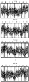
- FIG. 5A to FIG. 5D are diagrams showing example measurement signals for each speaker.
- FIG. 5A shows an example of a measurement signal corresponding to the speaker 11.
- the measurement signal shown in FIG. 5A is the same as the measurement sound shown in FIG. 4A , and the same as the example pink noise being the measurement sound generated in the processing of S11.
- FIG. 5B shows an example of a measurement signal corresponding to the speaker 12.
- the measurement signal of FIG. 5B is the same signal as a time base waveform shown in FIG. 4B .
- the measurement signal of FIG. 5B is a time base waveform obtained by moving a component H being a portion (e.g., 16384 samples) of the back end of the example pink noise generated in the processing of S11, to the front end.
- FIG. 5C shows an example of a measurement signal corresponding to the speaker 13.
- the measurement signal of FIG. 5C is a time base waveform obtained by moving a component G being a portion (e.g., 16384 samples) of the back end of the measurement signal corresponding to the speaker 12 shown in FIG. 5B , to the front end.
- FIG. 5D shows an example of a measurement signal corresponding to the speaker 18.
- the measurement signal of FIG. 5D is a time base waveform obtained by moving a component B being a portion (e.g., 16384 samples) of the back end of the measurement signal corresponding to the speaker 17, to the front end.
- the audio device 10 moves a component, being a portion of the back end of the measurement signal, to the front end, and generates a measurement signal of each speaker.
- the component A to the component H correspond to the plurality of first measurement signals of the present disclosure, respectively.
- the measurement signal corresponding to each speaker disposes the component A to the component H in a different time zone on a time axis.
- the measurement signal corresponding to each speaker corresponds to the second measurement signal of the present disclosure.
- FIG. 6A to FIG. 6D are diagrams showing a third measurement signal for each speaker.
- FIG. 6A shows an example of a third measurement signal corresponding to the speaker 11.
- the third measurement signal corresponding to the speaker 11 is a signal obtained by copying and prepending the component H being a portion of the back end of the second measurement signals shown in FIG. 5A .
- FIG. 6B shows an example of a third measurement signal corresponding to the speaker 12.
- the third measurement signal corresponding to the speaker 12 is a signal obtained by copying and prepending the component G being a portion of the back end of the second measurement signals shown in FIG. 5B .
- FIG. 6C shows an example of a third measurement signal corresponding to the speaker 13.
- the third measurement signal corresponding to the speaker 13 is a signal obtained by copying and prepending the component F being a portion of the back end of the second measurement signals shown in FIG. 5C .
- FIG. 6D shows an example of a third measurement signal corresponding to the speaker 18.
- the third measurement signal corresponding to the speaker 18 is a signal obtained by copying and prepending the component A being a portion of the back end of the second measurement signals shown in FIG. 5D .
- the audio device 10 moves a component being a portion (e.g., 16384 samples) of the back end of the second measurement signal to the front end, and generates a third measurement signal of each speaker.
- a third measurement signal is the same as a signal in a situation in which a signal at the back end of the second measurement signal wraps around to the front end.
- the third measurement signal although being a signal of one period, is synonymous with a signal after the second and subsequent periods of a periodic signal.
- the audio device 10 starts measurement (S14).
- the audio device 10 outputs a respective third measurement signal to each of the speaker 11 to the speaker 18 simultaneously.
- the audio device 10 starts collecting (recording) sound, using the microphone 20.
- the audio device 10 based on the collected sound signal collected with the microphone 20 and the measurement sound (e.g., pink noise) generated in S11, measures an impulse response corresponding to the acoustic characteristics of each speaker (S15).
- the measurement sound e.g., pink noise
- FIG. 7A shows an amplitude waveform on the time axis of a collected sound signal collected with the microphone 20.
- the audio device 10 removes a partial head (e.g., 16384 samples) from the collected sound signal collected with the microphone 20, and takes out a collected sound signal of, for example, 131072 samples corresponding to the time length of the measurement sound generated in S11.
- a partial head e.g., 16384 samples
- the audio device 10 obtains an impulse response by convolving the inverse function of the measurement sound generated in S11 to the collected sound signal. More specifically, the audio device 10 applies the Fourier transform to the measurement sound X(t) generated in S11 to obtain a frequency signal X( ⁇ ), and applies the Fourier transform to the collected sound signal Y(t) shown in FIG. 7B to obtain a frequency signal Y( ⁇ ). Then, a frequency signal H( ⁇ ) of the impulse response H(t) is represented by the following formula (1), based on the cross-spectral method.
- H ⁇ conj Y ⁇ ⁇ X ⁇ / conj X ⁇ ⁇ X ⁇
- conj (X( ⁇ )) represents a conjugate complex number of X( ⁇ )
- conj (Y( ⁇ )) represents a conjugate complex number of Y( ⁇ ).
- the audio device 10 is able to obtain the impulse response H(t) by applying the inverse Fourier transform to the frequency signal H( ⁇ ) obtained by the above formula (1).
- FIG. 8 is a diagram showing an amplitude waveform on the time axis of an impulse response H(t).
- the collected sound signal collected with the microphone 20 includes a plurality of third measurement signals simultaneously outputted from the speakers 11 to 18.
- the plurality of third measurement signals dispose each of the component A to the component H in a different time zone on a time axis. For example, a signal obtained by removing the head 16384 samples of the third measurement signal outputted from the speaker 11 is the same as the measurement sound generated in S11. Therefore, as shown in FIG. 8 , the head 16384 samples of the impulse response H(t) correspond to the impulse response of the output third measurement signal outputted from the speaker 11.
- a signal obtained by removing, for example, the head 16384 samples of the third measurement signal outputted from the speaker 12 is a signal obtained by temporally shifting the measurement sound generated in S11 by 16384 samples. Therefore, the impulse response of the third measurement signal outputted from the speaker 12 appears at a position shifted backward only by 16384 samples, for example. Similarly, the impulse response of the third measurement signal outputted from each speaker appears in a different time zone on a time axis.
- the audio device 10 is able to obtain acoustic characteristics of each of the speaker 11 to the speaker 18 by taking out, for example, 16384 samples of the impulse response H(t).
- the measurement method shown in the present embodiment is able to obtain the impulse response (e.g., the acoustic characteristics) of a plurality of speakers, by a single measurement. While the number of speakers according to the present embodiment is eight, the number of speakers may be further more or may be less.
- the measurement method shown in the present embodiment is able to obtain the impulse response (the acoustic characteristics) of a plurality of speakers, by a single measurement, regardless of the number of speakers. Accordingly, the measurement method shown in the present embodiment is able to reduce an increase in the number of times of measurement even when the number of speakers is increased.
- the frequency signal H( ⁇ ) of the impulse response shown in the above formula (1) is premised on the principle of circular convolution in which the impulse response H(t) is repeated periodically on a time axis. Therefore, a measurement signal (a measurement sound to be outputted from a speaker) being a signal of one period is unable to satisfy the principle of circular convolution.
- the third measurement signal to be outputted from each speaker since being generated such that a signal at the back end of the second measurement signal wraps around to the front end, is able to be treated in the same manner as the signal after the second and subsequent periods of the periodic signal. Therefore, the measurement method shown in the present embodiment is able to satisfy the principle of circular convolution and correctly obtain the frequency signal H( ⁇ ) of an impulse response by the above formula (1).
- the audio device 10 may take out a collected sound signal of, for example, 1347456 samples that is longer by, e.g., 16384 samples than the time length of the measurement sound generated in S11, among the collected sound signals collected with the microphone 20, and may obtain an impulse response.
- the time length of each of the plurality of first measurement signals may be the same as the time length of the acoustic characteristics of to be measured and may be longer than the time length of the acoustic characteristics. For example, in a case in which the audio device 10 and the speakers 11 to 18 are connected by wireless communication, timing at which the speakers 11 to 18 output a third measurement signal may shift. In a case in which the time length of each of the plurality of first measurement signals (the component A to the component H) is the same as the time length of the acoustic characteristics, and the timing at which the third measurement signal is outputted shifts, impulse responses corresponding to respective speakers among the impulse responses H(t) overlap on a time axis.
- the impulse responses corresponding to respective speakers among the impulse responses H(t) do not overlap on a time axis, and thus the impulse response of each speaker is able to be taken out.
- the impulse responses corresponding to respective speakers do not overlap on a time axis even when the third measurement signal is not simultaneously outputted from all the speakers 11 to 18, and the impulse response of each speaker is able to be taken out.
- the audio device 10 may generate a measurement sound (a fourth measurement signal) of, for example, pink noise of a time length of the acoustic characteristics and a time length based on the number of speakers, and may generate the second measurement signal by moving the component A to the component H corresponding to the first measurement signal of each speaker, among the pink noise being the fourth measurement signal, to each time zone.
- the audio device 10 may generate a first measurement signal of each speaker individually, and may generate a second measurement signal by arranging generated first measurement signals on a time axis. In such a case as well, the audio device 10 generates a second measurement signal by disposing a plurality of first measurement signals in respective different time zones on a time axis.
- the audio device, the microphone, and the speaker may be built into one housing.
- the audio device may output a sound according to a measurement signal from the built-in speaker, and may collect the sound according to a measurement signal with the built-in microphone.
- the number of microphones may be not only one but two or more.
Landscapes
- Physics & Mathematics (AREA)
- Engineering & Computer Science (AREA)
- Acoustics & Sound (AREA)
- Signal Processing (AREA)
- Health & Medical Sciences (AREA)
- Otolaryngology (AREA)
- General Health & Medical Sciences (AREA)
- Circuit For Audible Band Transducer (AREA)
- Measurement Of Mechanical Vibrations Or Ultrasonic Waves (AREA)
Applications Claiming Priority (1)
| Application Number | Priority Date | Filing Date | Title |
|---|---|---|---|
| JP2021049451A JP7647219B2 (ja) | 2021-03-24 | 2021-03-24 | 測定方法および測定装置 |
Publications (2)
| Publication Number | Publication Date |
|---|---|
| EP4064727A2 true EP4064727A2 (fr) | 2022-09-28 |
| EP4064727A3 EP4064727A3 (fr) | 2022-10-05 |
Family
ID=80787290
Family Applications (1)
| Application Number | Title | Priority Date | Filing Date |
|---|---|---|---|
| EP22162666.6A Withdrawn EP4064727A3 (fr) | 2021-03-24 | 2022-03-17 | Procédé et appareil de mesure |
Country Status (3)
| Country | Link |
|---|---|
| US (1) | US11812230B2 (fr) |
| EP (1) | EP4064727A3 (fr) |
| JP (1) | JP7647219B2 (fr) |
Citations (1)
| Publication number | Priority date | Publication date | Assignee | Title |
|---|---|---|---|---|
| WO2018173131A1 (fr) | 2017-03-22 | 2018-09-27 | ヤマハ株式会社 | Dispositif de traitement de signal |
Family Cites Families (7)
| Publication number | Priority date | Publication date | Assignee | Title |
|---|---|---|---|---|
| JP2002101500A (ja) | 2000-09-22 | 2002-04-05 | Matsushita Electric Ind Co Ltd | 音場測定装置 |
| JP4376035B2 (ja) * | 2003-11-19 | 2009-12-02 | パイオニア株式会社 | 音響特性測定装置及び自動音場補正装置並びに音響特性測定方法及び自動音場補正方法 |
| JP4210859B2 (ja) * | 2005-10-31 | 2009-01-21 | ソニー株式会社 | 周波数特性およびインパルス応答の立ち上がり時点の測定方法と、音場補正装置 |
| JP2008197284A (ja) * | 2007-02-09 | 2008-08-28 | Sharp Corp | フィルタ係数算出装置、フィルタ係数算出方法、制御プログラム、コンピュータ読み取り可能な記録媒体、および、音声信号処理装置 |
| JP4609502B2 (ja) | 2008-02-27 | 2011-01-12 | ヤマハ株式会社 | サラウンド出力装置およびプログラム |
| WO2013006324A2 (fr) * | 2011-07-01 | 2013-01-10 | Dolby Laboratories Licensing Corporation | Commande de système de lecture audio |
| US9398392B2 (en) * | 2014-06-30 | 2016-07-19 | Microsoft Technology Licensing, Llc | Audio calibration and adjustment |
-
2021
- 2021-03-24 JP JP2021049451A patent/JP7647219B2/ja active Active
-
2022
- 2022-03-17 EP EP22162666.6A patent/EP4064727A3/fr not_active Withdrawn
- 2022-03-23 US US17/701,859 patent/US11812230B2/en active Active
Patent Citations (1)
| Publication number | Priority date | Publication date | Assignee | Title |
|---|---|---|---|---|
| WO2018173131A1 (fr) | 2017-03-22 | 2018-09-27 | ヤマハ株式会社 | Dispositif de traitement de signal |
Also Published As
| Publication number | Publication date |
|---|---|
| US20220312137A1 (en) | 2022-09-29 |
| EP4064727A3 (fr) | 2022-10-05 |
| US11812230B2 (en) | 2023-11-07 |
| JP2022147961A (ja) | 2022-10-06 |
| JP7647219B2 (ja) | 2025-03-18 |
Similar Documents
| Publication | Publication Date | Title |
|---|---|---|
| JP4466658B2 (ja) | 信号処理装置、信号処理方法、プログラム | |
| JP5811993B2 (ja) | ヘッドホン、ヘッドホンのノイズ低減方法、ノイズ低減処理用プログラム | |
| JP2008122729A (ja) | ノイズ低減装置、ノイズ低減方法、ノイズ低減プログラムおよびノイズ低減音声出力装置 | |
| EP2914020A1 (fr) | Dispositif de détection de vibrations, dispositif de mesure de vibrations, système de mesure et procédé de mesure | |
| JPH0787633B2 (ja) | 電気−音響変換装置 | |
| CN109379689A (zh) | 扬声器总谐波失真测量方法、装置、存储介质及测量系统 | |
| EP1501334A1 (fr) | Dispositif et procede de mesure de caracteristique d'emission, et amplificateur | |
| CN112509595A (zh) | 音频数据处理方法、系统及存储介质 | |
| US8233630B2 (en) | Test apparatus, test method, and computer program | |
| US9082410B2 (en) | Audio processing apparatus, audio processing method, and image capturing apparatus | |
| EP4064727A2 (fr) | Procédé et appareil de mesure | |
| CN100549638C (zh) | 测量冲激响应的频率特性和上升沿的方法、以及声场校正装置 | |
| US12356160B2 (en) | Multi-channel audio system, multi-channel audio device, program, and multi-channel audio playback method | |
| JP4892095B1 (ja) | 音響補正装置、及び音響補正方法 | |
| JP5200784B2 (ja) | スピーカ診断装置および音響システム | |
| US7907737B2 (en) | Acoustic apparatus | |
| JPH11262081A (ja) | 遅延時間設定方式 | |
| JP5880753B2 (ja) | ヘッドホン、ヘッドホンのノイズ低減方法、ノイズ低減処理用プログラム | |
| JP4162329B2 (ja) | インターコムシステムおよびmri装置 | |
| WO2022209171A1 (fr) | Dispositif de traitement de signal, procédé de traitement de signal et programme | |
| CN115426609A (zh) | 耳机噪声的测试方法、装置、测试设备及计算机介质 | |
| Leitão et al. | Adaptive room equalization in the frequency domain | |
| KR101664950B1 (ko) | 마이크로폰과 라우드 스피커 쌍의 왜곡 제거를 위한 임펄스 응답 측정 방법 | |
| CN116567396A (zh) | 语音播报方法、装置、设备、存储介质和程序产品 | |
| JP2013073027A (ja) | 音響再生装置および音響再生方法 |
Legal Events
| Date | Code | Title | Description |
|---|---|---|---|
| PUAI | Public reference made under article 153(3) epc to a published international application that has entered the european phase |
Free format text: ORIGINAL CODE: 0009012 |
|
| STAA | Information on the status of an ep patent application or granted ep patent |
Free format text: STATUS: THE APPLICATION HAS BEEN PUBLISHED |
|
| PUAL | Search report despatched |
Free format text: ORIGINAL CODE: 0009013 |
|
| AK | Designated contracting states |
Kind code of ref document: A2 Designated state(s): AL AT BE BG CH CY CZ DE DK EE ES FI FR GB GR HR HU IE IS IT LI LT LU LV MC MK MT NL NO PL PT RO RS SE SI SK SM TR |
|
| AK | Designated contracting states |
Kind code of ref document: A3 Designated state(s): AL AT BE BG CH CY CZ DE DK EE ES FI FR GB GR HR HU IE IS IT LI LT LU LV MC MK MT NL NO PL PT RO RS SE SI SK SM TR |
|
| RIC1 | Information provided on ipc code assigned before grant |
Ipc: H04S 7/00 20060101ALI20220830BHEP Ipc: H04R 5/04 20060101ALI20220830BHEP Ipc: H04R 3/12 20060101AFI20220830BHEP |
|
| STAA | Information on the status of an ep patent application or granted ep patent |
Free format text: STATUS: REQUEST FOR EXAMINATION WAS MADE |
|
| 17P | Request for examination filed |
Effective date: 20221215 |
|
| RBV | Designated contracting states (corrected) |
Designated state(s): AL AT BE BG CH CY CZ DE DK EE ES FI FR GB GR HR HU IE IS IT LI LT LU LV MC MK MT NL NO PL PT RO RS SE SI SK SM TR |
|
| STAA | Information on the status of an ep patent application or granted ep patent |
Free format text: STATUS: EXAMINATION IS IN PROGRESS |
|
| 17Q | First examination report despatched |
Effective date: 20240902 |
|
| STAA | Information on the status of an ep patent application or granted ep patent |
Free format text: STATUS: THE APPLICATION IS DEEMED TO BE WITHDRAWN |
|
| 18D | Application deemed to be withdrawn |
Effective date: 20251001 |