EP4065285B1 - Spender mit kontinuierlichem sprühstrahl - Google Patents
Spender mit kontinuierlichem sprühstrahl Download PDFInfo
- Publication number
- EP4065285B1 EP4065285B1 EP20816452.5A EP20816452A EP4065285B1 EP 4065285 B1 EP4065285 B1 EP 4065285B1 EP 20816452 A EP20816452 A EP 20816452A EP 4065285 B1 EP4065285 B1 EP 4065285B1
- Authority
- EP
- European Patent Office
- Prior art keywords
- dispenser
- fluid
- diaphragm
- trigger
- pump chamber
- Prior art date
- Legal status (The legal status is an assumption and is not a legal conclusion. Google has not performed a legal analysis and makes no representation as to the accuracy of the status listed.)
- Active
Links
Images


Classifications
-
- B—PERFORMING OPERATIONS; TRANSPORTING
- B05—SPRAYING OR ATOMISING IN GENERAL; APPLYING FLUENT MATERIALS TO SURFACES, IN GENERAL
- B05B—SPRAYING APPARATUS; ATOMISING APPARATUS; NOZZLES
- B05B11/00—Single-unit hand-held apparatus in which flow of contents is produced by the muscular force of the operator at the moment of use
- B05B11/01—Single-unit hand-held apparatus in which flow of contents is produced by the muscular force of the operator at the moment of use characterised by the means producing the flow
- B05B11/10—Pump arrangements for transferring the contents from the container to a pump chamber by a sucking effect and forcing the contents out through the dispensing nozzle
- B05B11/1001—Piston pumps
- B05B11/1009—Piston pumps actuated by a lever
- B05B11/1011—Piston pumps actuated by a lever without substantial movement of the nozzle in the direction of the pressure stroke
-
- B—PERFORMING OPERATIONS; TRANSPORTING
- B05—SPRAYING OR ATOMISING IN GENERAL; APPLYING FLUENT MATERIALS TO SURFACES, IN GENERAL
- B05B—SPRAYING APPARATUS; ATOMISING APPARATUS; NOZZLES
- B05B11/00—Single-unit hand-held apparatus in which flow of contents is produced by the muscular force of the operator at the moment of use
- B05B11/01—Single-unit hand-held apparatus in which flow of contents is produced by the muscular force of the operator at the moment of use characterised by the means producing the flow
- B05B11/10—Pump arrangements for transferring the contents from the container to a pump chamber by a sucking effect and forcing the contents out through the dispensing nozzle
- B05B11/1038—Pressure accumulation pumps, i.e. pumps comprising a pressure accumulation chamber
- B05B11/104—Pressure accumulation pumps, i.e. pumps comprising a pressure accumulation chamber the outlet valve being opened by pressure after a defined accumulation stroke
-
- B—PERFORMING OPERATIONS; TRANSPORTING
- B05—SPRAYING OR ATOMISING IN GENERAL; APPLYING FLUENT MATERIALS TO SURFACES, IN GENERAL
- B05B—SPRAYING APPARATUS; ATOMISING APPARATUS; NOZZLES
- B05B1/00—Nozzles, spray heads or other outlets, with or without auxiliary devices such as valves, heating means
- B05B1/34—Nozzles, spray heads or other outlets, with or without auxiliary devices such as valves, heating means designed to influence the nature of flow of the liquid or other fluent material, e.g. to produce swirl
- B05B1/3405—Nozzles, spray heads or other outlets, with or without auxiliary devices such as valves, heating means designed to influence the nature of flow of the liquid or other fluent material, e.g. to produce swirl to produce swirl
- B05B1/341—Nozzles, spray heads or other outlets, with or without auxiliary devices such as valves, heating means designed to influence the nature of flow of the liquid or other fluent material, e.g. to produce swirl to produce swirl before discharging the liquid or other fluent material, e.g. in a swirl chamber upstream the spray outlet
- B05B1/3421—Nozzles, spray heads or other outlets, with or without auxiliary devices such as valves, heating means designed to influence the nature of flow of the liquid or other fluent material, e.g. to produce swirl to produce swirl before discharging the liquid or other fluent material, e.g. in a swirl chamber upstream the spray outlet with channels emerging substantially tangentially in the swirl chamber
-
- B—PERFORMING OPERATIONS; TRANSPORTING
- B05—SPRAYING OR ATOMISING IN GENERAL; APPLYING FLUENT MATERIALS TO SURFACES, IN GENERAL
- B05B—SPRAYING APPARATUS; ATOMISING APPARATUS; NOZZLES
- B05B11/00—Single-unit hand-held apparatus in which flow of contents is produced by the muscular force of the operator at the moment of use
- B05B11/0005—Components or details
- B05B11/0008—Sealing or attachment arrangements between sprayer and container
-
- B—PERFORMING OPERATIONS; TRANSPORTING
- B05—SPRAYING OR ATOMISING IN GENERAL; APPLYING FLUENT MATERIALS TO SURFACES, IN GENERAL
- B05B—SPRAYING APPARATUS; ATOMISING APPARATUS; NOZZLES
- B05B11/00—Single-unit hand-held apparatus in which flow of contents is produced by the muscular force of the operator at the moment of use
- B05B11/0005—Components or details
- B05B11/0037—Containers
- B05B11/0039—Containers associated with means for compensating the pressure difference between the ambient pressure and the pressure inside the container, e.g. pressure relief means
- B05B11/0044—Containers associated with means for compensating the pressure difference between the ambient pressure and the pressure inside the container, e.g. pressure relief means compensating underpressure by ingress of atmospheric air into the container, i.e. with venting means
-
- B—PERFORMING OPERATIONS; TRANSPORTING
- B05—SPRAYING OR ATOMISING IN GENERAL; APPLYING FLUENT MATERIALS TO SURFACES, IN GENERAL
- B05B—SPRAYING APPARATUS; ATOMISING APPARATUS; NOZZLES
- B05B11/00—Single-unit hand-held apparatus in which flow of contents is produced by the muscular force of the operator at the moment of use
- B05B11/01—Single-unit hand-held apparatus in which flow of contents is produced by the muscular force of the operator at the moment of use characterised by the means producing the flow
- B05B11/10—Pump arrangements for transferring the contents from the container to a pump chamber by a sucking effect and forcing the contents out through the dispensing nozzle
- B05B11/1042—Components or details
- B05B11/1066—Pump inlet valves
- B05B11/1067—Pump inlet valves actuated by pressure
-
- B—PERFORMING OPERATIONS; TRANSPORTING
- B05—SPRAYING OR ATOMISING IN GENERAL; APPLYING FLUENT MATERIALS TO SURFACES, IN GENERAL
- B05B—SPRAYING APPARATUS; ATOMISING APPARATUS; NOZZLES
- B05B11/00—Single-unit hand-held apparatus in which flow of contents is produced by the muscular force of the operator at the moment of use
- B05B11/01—Single-unit hand-held apparatus in which flow of contents is produced by the muscular force of the operator at the moment of use characterised by the means producing the flow
- B05B11/10—Pump arrangements for transferring the contents from the container to a pump chamber by a sucking effect and forcing the contents out through the dispensing nozzle
- B05B11/1042—Components or details
- B05B11/1073—Springs
- B05B11/1074—Springs located outside pump chambers
-
- B—PERFORMING OPERATIONS; TRANSPORTING
- B05—SPRAYING OR ATOMISING IN GENERAL; APPLYING FLUENT MATERIALS TO SURFACES, IN GENERAL
- B05B—SPRAYING APPARATUS; ATOMISING APPARATUS; NOZZLES
- B05B11/00—Single-unit hand-held apparatus in which flow of contents is produced by the muscular force of the operator at the moment of use
- B05B11/01—Single-unit hand-held apparatus in which flow of contents is produced by the muscular force of the operator at the moment of use characterised by the means producing the flow
- B05B11/10—Pump arrangements for transferring the contents from the container to a pump chamber by a sucking effect and forcing the contents out through the dispensing nozzle
- B05B11/1042—Components or details
- B05B11/1073—Springs
- B05B11/1077—Springs characterised by a particular shape or material
Definitions
- This application relates generally to trigger-activated pump dispensers and, more specifically, to a pump, including a bellows reservoir made from recyclable materials (e.g., a single grade of plastic or a set of plastics that are compatible with and amenable to recycling procedures), configured to dispense an extended stream or spray without continuous actuation after the pump engine has been properly primed.
- a bellows reservoir made from recyclable materials (e.g., a single grade of plastic or a set of plastics that are compatible with and amenable to recycling procedures), configured to dispense an extended stream or spray without continuous actuation after the pump engine has been properly primed.
- a class of pump dispensers can be made from post-consumer resin (PCR) ranging from 67% to 100%, in terms of PCR recycled content.
- PCR post-consumer resin
- dispensers made from a single grade of polymeric material, without reliance on any metallic or glass components, are particularly desirable insofar as they themselves can be converted into PCR base material without the need for disassembly or separation of plastic from non-plastics components.
- United States Patent 4,867,347 describes a pump chamber having a resiliently restorable flexible wall which could be made from standard plastics such as polypropylene. Restoring force is provided by a special form of the flexible wall, comprising at least one facet having a concave boundary and a curved surface portion interrupting the facet to induce bending thereof in the dispensing stroke, this bending producing a strong restoring force tending to restore the flexible wall to the rest condition.
- the curved surface portion - typically a cylindrical surface portion - is axially inclined to the facet and meets it along the concave boundary.
- the flexible wall has the shape of a polygonal pyramid with plural facets. While this structure can be molded integrally with adjacent components, the restoring force achieved was inconsistent and sometimes inadequate so that the design was never adopted in widespread commercial uses.
- Trigger sprayers are a class of dispensers in which a directional nozzle dispenses fluid along a known and expected flowpath. Such dispensers usually rely on atomization to evenly disperse the fluid and/or to create a mist therefrom. Consumers often prefer these types of dispensers for cleaning and personal care products precisely because of this predictable, projecting dispensing pattern.
- the trigger sprayer assembly itself is characterized by a closure that couples to a container, with a handle or trigger-type actuator positioned beneath the barrel of a horizontal projecting outlet.
- the outlet may include a rotatable nozzle assembly to open, close, and/or toggle between various types of spray patterns (mist, stream, wide cone, narrow cone, etc.). The position of the outlet is generally fixed relative to the container and closure.
- One such trigger is described in international patent publication number WO 2018/049373, filed on September 12, 2017 .
- pre-compression in trigger dispensers, it is also desirable to employ a "pre-compression" arrangement so that fluid is forcefully and completely dispensed upon the first actuation of the trigger (after an initial priming, when the dispenser is used for the very first time). In this manner, pre-compression reinforces and further ensures that the dispensing path will be consistent and known (i.e., without an initial stroke whereby the fluid fails to fully project and/or disperse as designed and intended).
- United States patent publication 2008/0230563 discloses a pre-compression style trigger sprayer.
- a pre-compression valve is employed to create predetermined pressure prior to actuation.
- the valve itself is an elastic diaphragm, while flexion springs are used to urge the actuator and piston into position.
- Document EP 0216043 A2 discloses a dispensing device for the discharge of liquids, particularly for the spraying of liquids, having a manually actuatable liquid dispensing device.
- the dispensing device is connected to a storage chamber which is under volume contraction and with which an outlet for the stored liquid communicates.
- at least one wall of the storage chamber can cooperate with a spring having flip-flop action with residual restoring force and a control valve on the outlet side is shifted into its open position in said flopped-over position.
- a trigger sprayer dispenser made from a single grade of polymeric material with continuous spray functionality would be desirable.
- An all-plastic, continuous trigger sprayer is contemplated that avoids the use of metal parts, elastomers, or other disparate and non-recyclable materials.
- a reservoir diaphragm is provided within the sprayer head, interposed between the actuation mechanism and the outlet, so as to ensure a steady flow of dispensed fluid is delivered even after actuation has ceased.
- the invention provides a continuous-spray trigger dispenser, which can be made without the use of metallic or other non-recyclable parts, in which a reservoir defined by a resiliently-deformable diaphragm is interposed along a fluid flow path between the outlet of a pump chamber and a nozzle outlet of the dispenser itself.
- the reservoir may be defined between resiliently deformable, faceted shell members whose resilient action may be supplemented with one or more biasing members, preferably of polymer material. Fluid is held within the reservoir volume.
- One or more valves may be provided to control the ingress of fluid into the reservoir from the pump chamber and/or the egress of fluid from the reservoir to the nozzle outlet.
- This arrangement enables a volume of fluid, desirably equal to and usually greater than the volume delivered with a single actuation stroke in the pump chamber, to be dispensed as a continuous stream. By continued or repeated actuation, a prolonged continuous dispensing may be available.
- the words “example” and “exemplary” mean an instance, or illustration. The words “example” or “exemplary” do not indicate a key or preferred aspect or embodiment.
- the word “or” is intended to be inclusive rather an exclusive, unless context suggests otherwise.
- the phrase “A employs B or C,” includes any inclusive permutation (e.g., A employs B; A employs C; or A employs both B and C).
- the articles “a” and “an” are generally intended to mean “one or more” unless context suggest otherwise.
- FIG. 1A illustrates an exemplary known trigger sprayer design.
- Spray head 20 includes a horizontally oriented barrel or channel 24 having a nozzle outlet 22 at its distal end.
- a trigger actuator 25 is positioned proximate to and beneath barrel 24.
- the trigger 25 is generally orthogonal to the orientation of the barrel 24 and its actuation is in a substantially horizontal direction (when the container is upright).
- a closure skirt 26 couples to the opening in a container (not shown), while the dip tube 28 extends into the container and draws fluid up into the body 29 and out the dispenser nozzle 22 by way of a pump mechanism (not shown).
- a plastic shroud may encase the body 29 to create a more streamlined aesthetic. In total, this arrangement ensures that, when used, the fluid is dispensed in a known and predictable path.
- FIG. 1B illustrates details of a prior art trigger sprayer which will help to highlight still other distinguishing features of certain aspects of the invention below.
- prior art trigger sprayer 10 includes a nozzle 12 and barrel 14. Internal flow channel 13 fluidically connects dip tube 18 (which extends into and draws fluid from the container) and the outlet formed in nozzle 12. Therebetween, pump body 19 is actuated by trigger 15.
- the pump 19 includes a metallic spring 19a which creates suction within the channel 13 when the trigger 15 is depressed and released. Glass or metal ball valve 18a temporarily seals channel 13 to facilitate dispensing and to avoid unwanted contamination or leakage of fluid from the container.
- Skirt 16 includes internally facing screw threads that couple to the container neck.
- trigger sprayers must be distinguished from dispensing pumps, where the fluid flows directly downward owing to the force of gravity.
- Most dispenser pumps rely on a reciprocating actuator head that is pushed downward (i.e., vertically). The nozzle moves with the head.
- This arrangement does not include a trigger and, instead, usually requires the actuator to have a flattened head.
- a trigger sprayer includes a movable member positioned proximate and beneath the nozzle (i.e., the dispensing outlet) so as to afford the user a sense of directional dispensing.
- most trigger dispensers are designed to atomize or disperse the fluid in a directed stream or spray.
- continuous spray trigger dispensers must be distinguished from conventional trigger sprayers.
- actuation of the trigger immediately draws fluid through the pump body and flow channel out of the nozzle.
- fluid is not dispensed once actuation, such as by pulling the trigger towards the closure, has ceased.
- a continuous sprayer possesses the ability (usually by way of a reservoir) to continue to dispense fluid for an appreciable period of time or dosage (i.e., at least 0.5 seconds and/or so that double the fluid normally drawn by a single stroke of actuation).
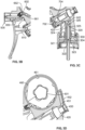
- FIGS 2A through 3D show various, exemplary aspects of a continuous trigger sprayer 100 embodying the invention.
- Figures 4 through 8 highlight specific components or combinations of components. Common reference numerals are employed throughout Figures 2A through 8 . In all instances, it will be understood that modifications and adjustments can be made to these components without departing from the continuous spray functionality and recyclable/single polymeric resin that provides many of the advantageous qualities of the invention.
- Trigger sprayer 100 includes an exterior shroud 200, preferably contoured to conceal the reservoir diaphragm 600 along with other portions of the pump engine.
- a trigger/actuation member 800 is pivotally attached to the pump body 400 and configured for grasping and squeezing actions by the user.
- the shroud 200 may be snap-fitted to one or more web structures or other attachment points formed on the exterior surfaces of the pump body 400.
- Shroud 200 will include appropriate apertures and define an appropriately shaped inner void to accommodate the various other structures herein although, with respect to the diaphragm biasing members 630, either the shroud 200 or an extension member of the body 400 (or a combination of the two) can be employed to ensure the appropriate force is consistently applied to the diaphragm 600.
- the sprayer 100 is rotatably or selectively attachable to a fluid container (not shown) by way of a closure cap 250.
- threads 251 and optional anti-back off teeth 252 are configured to ensure the cap 250 remains secured to the container.
- Cap 250 has a hollow tubular shape so as to allow for its attachment to the pump body 400 by way of inward and/or radially extending upper flange 253.
- a sealing gasket and/or plug-style connectors can be interposed between or positioned proximate to any one or combination of the cap 250, the lower extension stem 440 of the body 400, and the sealing plate 300.
- shroud 200 is formed as a two or multi-part, snap-together structure such as a clam shell structure as shown. Formations formed along the interface of the shells hold the shroud 200 together along a seam, while engaging features couple to the posts 441 formed on outer facings of the stem 440. In this manner, the head 110 of sprayer 100 presents a familiar, pistol-style dispenser, with a directional dispenser outlet 120 positioned above the trigger 800 when the sprayer 100 is in an upright position.
- Annular sealing plate 300 is concentrically received within the cap 250.
- Plate 300 has a circular shape with a central aperture 302 which is configured to receive and sealingly engage chaplet 320 and/or dip tube 340.
- Sealing plate 300 also has one or more venting apertures 304 passing through its surface to allow for the flow of make-up air into the container by way a path defined by the interstices and appropriate apertures in the pump chamber 420 and open space between an inner facing of the stem 420 and outer facing of the chaplet 320.
- Chaplet 320 has an elongated hollow cylindrical shape that is sized on its outer facings to snap and/or seal tightly to the aperture 302 and, separately by way of bead and groove or other coupling features, within a central channel 442 formed in the stem 440.
- dip tube 340 is held by way of similar bead and groove or other snap-fitting features.
- Annular flange 321 ensures a seal with the plate 300, while a frustoconical funnel 323 can extends downward to simplify insertion of the dip tube 340.
- An annular axial flange, extension, or cylinder 330 is spaced apart from the main body of the chaplet 320 to provide for a coupling gap 331.
- a flange, extension, or full cylinder from the stem 440 fits into gap 331 to couple the chaplet 320 to the body 400.
- the upper reaches 324 of the chaplet 320 have an inwardly stepped shape to conform to the dip tube 340.
- another frustoconical funnel-like formation serves as a seat 325 for check valve 360.
- check valve 360 is a plastic ball of sufficient mass/density that gravity naturally urges the valve into a sealed and closed position on the seat 325.
- the central channel 442 formed in the stem 440 is configured to seal and couple to the chaplet 320, but leaving sufficient axial space 443 to accommodate the valve 360.
- One or more inlets formed in the wall 444 separating the axial space 443 from the pump chamber 420 permits fluid to be drawn into the upper reaches of the pump 400.
- the sliding movement of the piston 420 within the chamber 420 in response to trigger 800 actuation will draw fluid into the chamber 420 and urge previously primed fluid into the diaphragm reservoir 600.
- make-up air also passes through air inlet 422, down through vents 304 and into the internal volume of the container, so as to avoid negative pressure differentials that can lead to deformation of the container.
- Pump body 400 includes a hollow cylinder portion 421 that, in conjunction with the piston 700, defines a variable volume pump chamber 420 that lies within the fluid flow path/receives fluid from the container.
- Chamber 420 is fluidically connected to the channel 442 to define a dispensing fluid flow channel running from the container, through the chaplet 320, sequentially into the chamber and then the reservoir diaphragm 600, and finally out of the nozzle outlet 500.
- the maximum volume of fluid received within the pump chamber is less than the volume of fluid capable of being stored within the reservoir diaphragm.
- a sliding piston 700 is received within the cylinder 421.
- Piston 700 connects to and/or cooperates with driving post 810 of the trigger 800, while coupling flanges 820, including snap-fit overhangs 821, attach the trigger 800 to the body 400.
- a resilient wedge 830 flexibly contacts the body 400 and urges the actuation lever 840 of trigger 800 away from the chamber 420 and piston 700, while a stopper 850 cooperates with a corresponding stopper on the body 400 to define the innermost extent to which the trigger 800 may be depressed.
- Post 810 may be coupled to the piston 700 to ensure the piston 700 is returned to its starting position (pre-actuation) after the trigger is depressed.
- one or more plastics biasing members could be positioned proximate to the trigger 800 and/or piston 700 to facilitate the necessary movements associated with actuation, including returning the piston to its starting position.
- Such biasing members could be positioned between the actuation lever 840 and the body 400 or piston 700 and/or within the pump chamber 420 itself. Other locations are also possible.
- the goal is to permit the trigger 800 sufficient movement to urge the piston 700 in a pumping stroke (i.e., so that fluid is drawn into and expelled from chamber 420) but then return the trigger 800 and piston 700 to a resting position in a relatively smooth and automatic fashion so as to enable additional actuating strokes.
- Piston 700 has a cup-like shape, with the open end receiving the post 810 on the inner surface 702.
- a catch 704 may be provided to ensure proper engagement so that the trigger 800 moves in concert with the piston 700.
- a first flared outer surface or wing 710 forms a sliding seal at the lower-most regions of chamber 420/cylinder 421.
- An upper flared surface or wing 720 also conforms the cylinder 421 to form a separate sliding seal, with the wing 720 axially offset above wing 710. Wing 720 blocks leakage and unwanted egress of fluid out of chamber 420, while wing 710 controls ingress of air into chamber 420. Further, the movement of piston 700 along the axis of cylinder 421 creates sufficient suction to move fluid through the body 400, thereby driving the pump mechanism.
- the terminal edge of wing 710 and/or 720 may serve as a stopper that prevent further axial movement of the piston 700 within the cylinder 421. This can also serve as a further safeguard, in conjunction with stopper 450 to prevent the trigger 800 from being actuated or operated in a manner that misaligns or damages the various moving parts.
- Solid top panel 730 of piston 700 drives fluid that was drawn into the chamber 420 through an outlet 423.
- Outlet is seal by a disc or flap valve 430 seated over the outlet 423.
- Valve 430 may provide pre-compression functionality but, at a minimum controls flow of fluid into the diaphragm reservoir 600.
- Valve 430 may be a simple flap or floating disc, with both gravity and pressure from fluid stored above the chamber 420 (i.e., in reservoir 600) helping to keep the valve 430 properly seated.
- Flow connector element 450 fits and bridges the space between the chamber 420 and reservoir 600.
- Element 450 may include an elongated C-shaped, channel-defining portion 451 with a snap-fitting cover 452. Between portions 451 and 452, a channel 453 redirects fluid passing through an annular aperture and toward the inlet 601 of reservoir 600.
- element 450 could be integrally molded into the main body 400, although use of cover 452 simplifies assembly of the valve 430.
- a retaining ring or feature 460 is formed in the upper reaches of body 400.
- Feature 460 is configured to secure the diaphragm reservoir 600 in place at attachment points 603.
- Ring or extension strip 461 may include coupling features that cooperate with similar features formed on the inner or outer surface of the annular walls 611, 621 of diaphragm shell members 610, 620. While shown as a single, vertically oriented hoop, strip 461 could be formed as a web or plurality of members shaped to receive the diaphragm 600 in any orientation, so long as its inlet 601 and outlet 602 are properly aligned with the flow channel defined by body 400 and described elsewhere herein. In some aspects, the extension 461 could be shaped to also accommodate the diaphragm biasing members 630.
- Reservoir diaphragm 600 is interposed along the fluid flow path between the outlet 423 of the pump chamber 420 and the nozzle outlet 500 of the sprayer itself.
- fluid is held within the volume defined by the shell members 610, 620, with valve 430 and diaphragm outlet valve 660 controlling the ingress and egress of fluids.
- This arrangement ensures that a volume of fluid, equal to or greater than the volume delivered with a single actuation stroke, may be dispensed as a continuous stream. Further, by continued actuation during dispensing, it is possible to continuously dispense fluid from the sprayer 100 for significantly longer periods of time than is otherwise possible by repeated actuation of a conventional trigger sprayer alone.
- the volume of fluid held in the reservoir 600 is at least 1, 1.5, 2.0, 2.5, 3, 4, 5 and even up to 10, 15, or 20 times or times larger than the volume of fluid delivered by a single actuation stroke of trigger 800 and piston 700 (i.e., the maximum volume of fluid received in the pumping chamber 420 from the container). Additionally or alternatively, this arrangement enables sprayer 100 to deliver a continuous and uninterrupted stream or atomized spray of fluid for at least 0.5, 1, 2, 3, 4, 5, and even up 10 or 15 seconds after actuation has ceased.
- the user may be possible for the user to recharge the reservoir 600 through renewed actuation (i.e., after an interim between the initial dispensing stroke) so as to sustain even longer continuous spray times, possibly even sustaining continuous spraying action until the container is emptied.
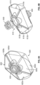
- the structure of diaphragm 600 includes two separate shells 610, 620 of similar shape, size, and construction. Each includes a cylindrical sidewall 611, 622 which include coupling features to attach to the body 400 (via feature 460 or, more specifically, extension ring 461) and/or to one another.
- the sidewalls 611, 622 should be of sufficient strength and thickness to withstand deformation of their respective top panels 612, 622 without buckling, decoupling, or otherwise comprising the flow path and function of the sprayer 100.
- One or more cooperating radial fins, teeth, indents/detents, or other formations may be provided on the inner and/or outer facings of the sidewalls 611, 622 to lock each shell in place, as well as interfacing with the feature 460 to prevent rotation or movement of the diaphragm 600 relative to the body 400.
- Inlet 601 and outlet 602 are provided in one or both of the sidewalls 611, 622.
- the port for each can be formed at their junction by way of an appropriate cutout or aperture.
- the positioning of the inlet 601 and 602 will be spaced apart sufficiently to ensure each connects to the remaining flow path (i.e., inlet 601 fluidically attaches to the connector 450 and the outlet to the nozzle 500).
- the inlet 601 and outlet 602 can be positioned apart around the circumference of the diaphragm at an angle greater than 90° and less than 180°, although other arrangements and/or multiple ports all connecting to the final flow path could be provided.
- a flap or check valve could be provided proximate to inlet 601 to act as a further safeguard against unwanted leakage from the reservoir 600.
- diaphragm 600 should be positioned axially above the entirety of the pump chamber 420. Further, the inlet 601 should be elevated in comparison to the position/axial height of the outlet 602. Positioning of these elements ensures that fluid preferentially flows out of the diaphragm 600 and into the nozzle 500. In aspects of the invention, after filling by way of one or repeated actuation strokes, the diaphragm 600 will drain completely or at least to a level below the inlet 601
- a seat 613, 623 is provided in the top panel 612, 622. These seats 613, 623 engage separate biasing members 630 which exert squeezing force on the diaphragm 600. Separately, multiple facets 612a, 622a are formed in the top panels 612, 622 to provide resilient deformability to the diaphragm 600. In this manner, fluid entering the reservoir 600 can accumulate by expanding the diaphragm 600 outward in conformance with facets 612a, 622a. When sufficient expansion has occurred, biasing members 630 provide squeezing force to expel the fluid through the outlet 602, while overcoming whatever force might be exerted by diaphragm outlet valve 660. Dispensing will continue in this manner until the diaphragm 600 and the fluid held within it return to its original condition of stasis.
- each facet has a gently sloped planar surface relative to the plane defined by the terminal edge of the annular sidewall 611, 621 (or, in the alternative, by the plane that is orthogonal to the flattened surfaces of seats 613, 623.
- This arrangement imparts a concave or convex, pyramidal shape to each top panel 612, 622, with both panels preferably (but not necessarily) being concave or convex.
- the sidewalls 611, 621 serve as an annular support as the facets 612a, 622a are flexed and stressed.
- Support ribs 612b, 622b connect between the sidewall 611, 621 and seats 613, 623 to facilitate the resiliency and strength of the diaphragm 600. Additional indents and features may be formed in the walls 611, 621 and/or top panels 612, 622 further enhance these traits. Ribs 612b, 622b also define the individual facets 612a, 622a, so that having 5 ribs yields 5 facets, etc., which is a preferred aspect. Nevertheless, while 5 ribs and facets are shown here, it will be understood that any number is possible, with the precise number impacting the resilience and strength of the resultant diaphragm 600, as well as its ability to accommodate fluctuating fluid pressures within it. Any whole number from 3 to 12 facets and ribs should have particular utility in accomplishing the goals of the invention.
- Each facet 612a, 622a may include a flattened portion 612c, 622c and a scalloped or cylindrical formation 612d, 622d at its top and/or bottom edge boundaries (i.e., where the flat portion 612c, 622c, joins and connects to the seat 613, 623 and the sidewall 611, 621, respectively speaking).
- These formations 612d, 622d can be curving so that when force is exerted on the seats 613, 623, the formations 612d, 622d deform and bend within that defined surface.
- Springs 630 (along with the other biasing members identified herein) can be plastic coils, leaf springs, or other similar structures. The amount of force exerted by springs 630 cooperates with the concave or convex shape of diaphragm 600 to ensure fluid is admitted and expelled in a regular manner that is initially responsive to actuation of the trigger 800.
- Diaphragm outlet valve 660 can be formed with a biasing member 661.
- the force exerted by the biasing member 661 should be less than the force exerted by the biasing members 630 when the reservoir 600 is sufficiently expanded. In this manner, it ensure continuous flow through the outlet 602 and out of the nozzle 500.
- Biasing member 661 urges a flap or blocking member 662 into position to seal the diaphragm reservoir 660 and retain fluid inside it.
- a tubular connector can be included in the valve 660 or a tubular extension can be integrally formed in one or both of the shells 610, 620, in either case the tubular member would ensure a proper seal is maintained while simultaneously accommodating any movement of the diaphragm 600 as it expands and contracts.
- a channel is formed to continue the fluid flowpath out of the diaphragm 600 and toward the outlet 510 of nozzle 500.
- a post 490 may be formed to coincide with the axial flowpath.
- Nozzle 500 attaches to post 490, with appropriate channels and apertures provided in the post 490 and the nozzle 500 to route fluid swirl chamber 520 and out of outlet 510.
- Nozzle 500 may include a circular shutter or blocking element 502 to direct part or all of the fluid flow through channels and apertures imparted in the nozzle into the swirl chamber 520, while attachment post 504 facilitates coupling of the nozzle 500 to the post 490.
- this arrangement of diaphragm 600 can also act as serve a pre-compression functionality, so that it is possible to dispense fluid upon the first actuation stroke.
- pre-compression is not required, and trigger sprayer 100 can be designed, with careful selection of the valves 430, 660 and biasing members 630, 661 (if present) informing the exact dispensing characteristics.
- a manual valve can supplement or replace valve 660.
- This manual valve could be as simple as a slidable member extending from the trigger into the flowpath proximate the nozzle 500 so as to block the flowpath. When slid downward, the reservoir 600 would dispense fluid until it is drained completely or until the user closes the slidable valve.
- Alternative arrangements could rely on a sideways movement of the entire trigger 800 (rather than a slidable member being inlaid or proximate to the actuation lever 840) to open and block the flowpath. Other control arrangements are possible as well.
- United States' patent publication number US2018/0318861A filed on April 25, 2018 discloses a polymeric diaphragm body. This body is coupled to a closure and, through appropriate inlets and outlets, suctions fluid from a container and expels it through the opening. Aspects of the construction and operation of such a diaphragm are applicable to the reservoir diaphragm contemplated herein.
- Other examples of appropriate bellows and other expandable structures that may serve as reservoirs, as well as biasing and alternative pump engines and actuation schemes, can be found in United States Patents 5,924,603 ; 6,193,112 ; 6,672,486 ; and 6,715,649 , as well as in United States Patent Publication 2017/0216864 .
- the bellows are shown in a vertical, fin-like arrangement, it may be possible to provide a bellows horizontally so to impart a hammer-head shape to the dispenser.
- the diaphragm 600 is still interposed between the connector 350 and nozzle 500, but the formation 460 lies in a horizontal rather than vertical plane (with each plane defined relative to the sprayer 100 in its upright, resting position). It may also be possible to provide a plurality of diaphragms of similar or differing constructions, with attendant alteration of the dispensing characteristics of the resulting sprayer. Still further modifications of this nature are possible without departing from the principles of invention.
- references to coupling, connection, or attachment in this disclosure are to be understood as encompassing any of the conventional means used in this field. This may take the form of snap- or force-fitting of components having tabs, grooves, and the like. Nevertheless, threaded connections, annular or partial bead-and-groove arrangements, cooperating cam members, and slot-and-flange assemblies could be employed. Adhesive and fasteners could also be used, although such components must be judiciously selected so as to retain the recyclable nature of the assembly.
- engagement may involve coupling or an abutting relationship.
- All components should be made of materials having sufficient flexibility and structural integrity, as well as a chemically inert nature. The materials should also be selected for workability, cost, and weight. Common polymers amenable to injection molding, extrusion, or other common forming processes are useful, although a single grade is preferred. As such, polypropylene is expected to have particular utility for every component described in Figures 2A through 8 .
- polypropylene e.g., polypropylene
- injection molding materials including without limitation polyethylene (including low density and other grades), polystyrene (including high impact and other grades), acrylonitrile butadiene styrene, and polyacetals (including polyoxymethylene, polyacetal, polyformaldehyde, and other grades).
Landscapes
- Containers And Packaging Bodies Having A Special Means To Remove Contents (AREA)
Claims (15)
- Handhebelbetätigter, kontinuierlicher Sprühspender (100) ohne Metallkomponenten, wobei der Spender Folgendes umfasst:einen Pumpenkörper (400), der einen Fluidströmungsweg definiert, der vollständig durch den Pumpenkörper verläuft, wobei der Pumpenkörper eine Verschlusskappe (250), eine Abgabedüse (500) und eine Pumpenkammer (420) aufweist, die einen bewegbaren Kolben (700) aufnimmt;eine Vorratsmembran (600), die am Pumpenkörper befestigt und oberhalb der Pumpenkammer positioniert ist, wobei die Vorratsmembran einen Einlass (601) zur Aufnahme von Fluid von der Pumpenkammer, einen Auslass (602), der mit der Abgabedüse verbunden ist, und eine Seitenwand aufweist, die mit zumindest einer ausdehnbaren, elastischen Platte verbunden ist, die sich als Reaktion auf Fluidakkumulation in der Membran und auf Vorspannkraft, die auf eine Außenfläche der Platte ausgeübt wird, bewegt; undeinen Handhebel (800), der nahe der Pumpenkammer schwenkbar mit dem Pumpenkörper verbunden ist, wobei der Handhebel ein Antriebselement aufweist, das den Kolben innerhalb der Pumpenkammer zwangsbewegt, wodurch das Volumen in einem Abschnitt der Pumpenkammer, der mit dem Fluidströmungsweg verbunden ist, variiert wird, um das Fluid entlang des Fluidströmungswegs zu drücken;wodurch in der Membran akkumulierendes Fluid gemäß zumindest einem der Folgenden kontinuierlich abgebbar ist: (i) für eine Zeitdauer, die länger ist, als die zur Betätigung des Handhebels erforderliche; und (ii) so, dass ein maximales Fluidvolumen, das im Abschnitt der Pumpenkammer aufgenommen wird, der mit dem Fluidströmungsweg verbunden ist, geringer ist als das Volumen der Vorratsmembran, wenn die Platte zumindest teilweise ausgedehnt ist,wobei die Membran zwei aneinander gekoppelte Schalenelemente (610, 620) umfasst, wobei zumindest ein Schalenelement die ausdehnbare, elastische Platte umfasst.
- Spender (100) nach Anspruch 1, wobei die Verschlusskappe eine Kernstütze (320) mit einem Rückschlagventil (360) umfasst, das im Fluidströmungsweg zwischen der Kernstütze und der Pumpenkammer angeordnet ist.
- Spender (100) nach Anspruch 2, wobei die Kernstütze und die Pumpenkammer jeweils Zusatzlufteinlässe (422) umfassen und wobei ein Dichtungsflügelelement, das am Kolben befestigt ist, den Durchtritt von Zusatzluft durch die Zusatzlufteinlässe ermöglicht, wenn der Kolben bei Betätigung des Handhebels bewegt wird.
- Spender (100) nach einem der Ansprüche 1 bis 3, wobei die Platte eine Vielzahl von Facetten (612a, 622a) umfasst, die durch Verstärkungsrippen (612b, 622b) getrennt sind, wobei die Vielzahl von Facetten eine konkave oder konvexe Pyramide bildet.
- Spender (100) nach Anspruch 4, wobei jede Facette einen abgeflachten Abschnitt, der die konkave oder konvexe Pyramide definiert, und eine oder zwei zylindrische Formationen umfasst, die nahe dem oberen und/oder unteren Rand des abgeflachten Abschnitts sind.
- Spender (100) nach einem der Ansprüche 1 bis 5, wobei alle Schalenelemente identisch sind.
- Spender (100) nach einem der Ansprüche 1 bis 6, wobei jedes Schalenelement eine zylindrische Seitenwand umfasst und der Einlass und Auslass durch die Seitenwände führen.
- Spender (100) nach einem der Ansprüche 1 bis 3, wobei die Membran eine zylindrische Seitenwand umfasst, sodass der Einlass und der Auslass durch die Seitenwand führen.
- Spender (100) nach einem der vorangegangenen Ansprüche, wobei ein Kunststoff-Vorspannelement (630) die Platte zusammendrückt.
- Spender (100) nach einem der vorangegangenen Ansprüche, wobei die Abgabedüse auf einer Stütze (490) befestigt ist, die im Fluidströmungsweg ausgebildet ist.
- Spender (100) nach Anspruch 10, wobei die Abgabedüse und die Stütze separate Strömungskanäle bilden, die in einer Wirbelkammer enden (520), die direkt neben einem Auslass der Abgabedüse liegt.
- Spender (100) nach einem der vorangegangenen Ansprüche, wobei die Vorratsmembran mit dem Pumpenkörper durch eine im Pumpenkörper ausgebildete Erweiterung gekoppelt ist.
- Spender (100) nach einem der vorangegangenen Ansprüche, wobei ein Verbindungselement den Fluidweg zwischen der Pumpenkammer und der Vorratsmembran definiert, wobei das Verbindungselement ein Ventil umschließt.
- Spender (100) nach einem der vorangegangenen Ansprüche, wobei der Pumpenkörper, der Handhebelaktuator und der Verschluss aus einem Polymermaterial derselben Qualität hergestellt sind.
- Spender (100) nach Anspruch 14, wobei das Polymermaterial aus Polypropylen besteht.
Applications Claiming Priority (2)
| Application Number | Priority Date | Filing Date | Title |
|---|---|---|---|
| US201962941005P | 2019-11-27 | 2019-11-27 | |
| PCT/EP2020/083637 WO2021105367A1 (en) | 2019-11-27 | 2020-11-27 | Continuous spray trigger dispenser |
Publications (2)
| Publication Number | Publication Date |
|---|---|
| EP4065285A1 EP4065285A1 (de) | 2022-10-05 |
| EP4065285B1 true EP4065285B1 (de) | 2024-06-26 |
Family
ID=73646327
Family Applications (1)
| Application Number | Title | Priority Date | Filing Date |
|---|---|---|---|
| EP20816452.5A Active EP4065285B1 (de) | 2019-11-27 | 2020-11-27 | Spender mit kontinuierlichem sprühstrahl |
Country Status (4)
| Country | Link |
|---|---|
| US (1) | US12472520B2 (de) |
| EP (1) | EP4065285B1 (de) |
| CN (1) | CN115023293B (de) |
| WO (1) | WO2021105367A1 (de) |
Families Citing this family (1)
| Publication number | Priority date | Publication date | Assignee | Title |
|---|---|---|---|---|
| KR102892894B1 (ko) * | 2025-03-05 | 2025-11-27 | 최희진 | 축압식 연속분무 스프레이어 및 그 분사 방법 |
Family Cites Families (21)
| Publication number | Priority date | Publication date | Assignee | Title |
|---|---|---|---|---|
| ES359722A1 (es) * | 1967-11-16 | 1970-06-16 | Harold Humphrey | Perfeccionamientos en la construccion de bombas elastome- ricas y valvulas de retencion. |
| US3726442A (en) * | 1971-02-17 | 1973-04-10 | Polypump Curacao Nv | Trigger pump and breather valve dispensing assembly |
| US3749290A (en) * | 1971-06-07 | 1973-07-31 | Leeds & Micallef | Trigger actuated pump |
| US4155487A (en) * | 1977-09-09 | 1979-05-22 | Blake William S | Trigger sprayer |
| US4241853A (en) * | 1978-05-17 | 1980-12-30 | James D. Pauls And J. Claybrook Lewis And Associates, Limited | Dispenser for either continuous or intermittent discharge |
| US4222501A (en) | 1978-07-24 | 1980-09-16 | James D. Pauls And J. Claybrook Lewis And Associates, Limited | Dual chamber, continuous action dispenser |
| DE3633173A1 (de) * | 1986-09-30 | 1988-04-07 | Mega Prod Verpack Marketing | Foerdereinrichtung |
| EP0262484A3 (de) * | 1986-09-30 | 1989-08-02 | MegaPlast Dosiersysteme GmbH & Co. | Fördereinrichtung |
| GB8629982D0 (en) | 1986-12-16 | 1987-01-28 | English Glass Co Ltd | Dispenser pump |
| US5673824A (en) | 1995-05-31 | 1997-10-07 | Taplast Srl | Plastic dosing pump for dispensing liquids from containers |
| IT1292958B1 (it) | 1997-02-28 | 1999-02-11 | Taplast Spa | Perfezionamento a pompa dosatrice per l'erogazione di sostanze liquide o dense da contenitori. |
| IT1315312B1 (it) | 2000-04-13 | 2003-02-10 | Taplast Spa | Pompa erogatrice multidose |
| IT1315351B1 (it) | 2000-05-26 | 2003-02-10 | Taplast Spa | Pompa a soffietto per la distribuzione di liquidi |
| DE102006012302A1 (de) * | 2006-03-15 | 2007-09-27 | Seaquist Perfect Dispensing Gmbh | Abgabevorrichtung |
| EP2517797B1 (de) | 2007-03-24 | 2020-05-27 | Afa Polytek B.V. | Vorverdichtungssystem für einen Flüssigkeitsspender und Verfahren zur Montage des Vorverdichtungssystems |
| JP6415884B2 (ja) * | 2014-07-24 | 2018-10-31 | キャニヨン株式会社 | トリガー式ポンプディスペンサ |
| GB2531997B (en) | 2014-10-20 | 2018-08-01 | Rieke Packaging Systems Ltd | Pump dispenser with deformable pump chamber wall |
| GB201518910D0 (en) | 2015-10-26 | 2015-12-09 | Rieke Packaging Systems Ltd | Dispensers |
| US11247221B2 (en) | 2016-09-12 | 2022-02-15 | Rieke Llc | Trigger sprayer |
| JP6803724B2 (ja) * | 2016-10-31 | 2020-12-23 | 株式会社吉野工業所 | トリガー式液体噴出器 |
| US11596961B2 (en) | 2018-04-13 | 2023-03-07 | Rieke Llc | Recyclable, pre-compression dispenser with trigger sprayer |
-
2020
- 2020-11-27 CN CN202080094770.0A patent/CN115023293B/zh active Active
- 2020-11-27 US US17/780,191 patent/US12472520B2/en active Active
- 2020-11-27 EP EP20816452.5A patent/EP4065285B1/de active Active
- 2020-11-27 WO PCT/EP2020/083637 patent/WO2021105367A1/en not_active Ceased
Also Published As
| Publication number | Publication date |
|---|---|
| US20220410193A1 (en) | 2022-12-29 |
| WO2021105367A1 (en) | 2021-06-03 |
| US12472520B2 (en) | 2025-11-18 |
| CN115023293B (zh) | 2024-12-06 |
| EP4065285A1 (de) | 2022-10-05 |
| CN115023293A (zh) | 2022-09-06 |
Similar Documents
| Publication | Publication Date | Title |
|---|---|---|
| US5664703A (en) | Pump device with collapsible pump chamber having supply container venting system and integral shipping seal | |
| EP2694221B1 (de) | Mit abzugshebel vorgesehene spender mit druckbetätigtem ventil | |
| EP0705142B1 (de) | Pumpvorrichtung mit faltbarer pumpenkammer mit mehreren funktionen | |
| CA2165314C (en) | Pump device with collapsible pump chamber having integral shipping seal | |
| EP2655893B1 (de) | Pumpvorrichtungen | |
| EP0784512B1 (de) | Pumpe mit verformbarer pumpenkammer und verdrängungskörper | |
| US20110240681A1 (en) | Low Cost Trigger Sprayer | |
| CN107074412A (zh) | 泵分配器 | |
| US20250018411A1 (en) | Single-polymer, reciprocating dispenser for foam products | |
| EP4065285B1 (de) | Spender mit kontinuierlichem sprühstrahl | |
| US8864052B2 (en) | Low cost trigger sprayer | |
| EP0784513B1 (de) | Montageverfahren mit abtrennbarem teil einer integral zusammenklappbaren pumpenkammer | |
| US11596961B2 (en) | Recyclable, pre-compression dispenser with trigger sprayer | |
| WO2023012238A1 (en) | Single polymer, dome-actuated pump | |
| EP2661327B1 (de) | Spender mit auslöser und mit vordruckventil | |
| KR102731392B1 (ko) | 거품 토출형 디스펜서 | |
| AU2024291747A1 (en) | Device and system for dispensing a liquid | |
| WO2025061899A1 (en) | All plastic fine misting dispenser with pre-compression functionality | |
| WO2025144052A1 (en) | Device and system for dispensing a liquid | |
| WO2025114616A1 (en) | Device and system for dispensing a liquid | |
| CA2201898C (en) | Pump device with collapsible pump chamber and including dunnage means | |
| US20110030551A1 (en) | Pump device and methods of making the same |
Legal Events
| Date | Code | Title | Description |
|---|---|---|---|
| STAA | Information on the status of an ep patent application or granted ep patent |
Free format text: STATUS: UNKNOWN |
|
| STAA | Information on the status of an ep patent application or granted ep patent |
Free format text: STATUS: THE INTERNATIONAL PUBLICATION HAS BEEN MADE |
|
| PUAI | Public reference made under article 153(3) epc to a published international application that has entered the european phase |
Free format text: ORIGINAL CODE: 0009012 |
|
| STAA | Information on the status of an ep patent application or granted ep patent |
Free format text: STATUS: REQUEST FOR EXAMINATION WAS MADE |
|
| 17P | Request for examination filed |
Effective date: 20220606 |
|
| AK | Designated contracting states |
Kind code of ref document: A1 Designated state(s): AL AT BE BG CH CY CZ DE DK EE ES FI FR GB GR HR HU IE IS IT LI LT LU LV MC MK MT NL NO PL PT RO RS SE SI SK SM TR |
|
| DAV | Request for validation of the european patent (deleted) | ||
| DAX | Request for extension of the european patent (deleted) | ||
| RIC1 | Information provided on ipc code assigned before grant |
Ipc: B05B 11/10 20230101ALI20231214BHEP Ipc: B05B 1/34 20060101ALI20231214BHEP Ipc: B05B 11/00 20060101AFI20231214BHEP |
|
| GRAP | Despatch of communication of intention to grant a patent |
Free format text: ORIGINAL CODE: EPIDOSNIGR1 |
|
| STAA | Information on the status of an ep patent application or granted ep patent |
Free format text: STATUS: GRANT OF PATENT IS INTENDED |
|
| INTG | Intention to grant announced |
Effective date: 20240119 |
|
| GRAS | Grant fee paid |
Free format text: ORIGINAL CODE: EPIDOSNIGR3 |
|
| GRAA | (expected) grant |
Free format text: ORIGINAL CODE: 0009210 |
|
| STAA | Information on the status of an ep patent application or granted ep patent |
Free format text: STATUS: THE PATENT HAS BEEN GRANTED |
|
| AK | Designated contracting states |
Kind code of ref document: B1 Designated state(s): AL AT BE BG CH CY CZ DE DK EE ES FI FR GB GR HR HU IE IS IT LI LT LU LV MC MK MT NL NO PL PT RO RS SE SI SK SM TR |
|
| REG | Reference to a national code |
Ref country code: GB Ref legal event code: FG4D |
|
| REG | Reference to a national code |
Ref country code: CH Ref legal event code: EP |
|
| REG | Reference to a national code |
Ref country code: DE Ref legal event code: R096 Ref document number: 602020033091 Country of ref document: DE |
|
| P01 | Opt-out of the competence of the unified patent court (upc) registered |
Free format text: CASE NUMBER: APP_43172/2024 Effective date: 20240723 |
|
| PG25 | Lapsed in a contracting state [announced via postgrant information from national office to epo] |
Ref country code: BG Free format text: LAPSE BECAUSE OF FAILURE TO SUBMIT A TRANSLATION OF THE DESCRIPTION OR TO PAY THE FEE WITHIN THE PRESCRIBED TIME-LIMIT Effective date: 20240626 |
|
| PG25 | Lapsed in a contracting state [announced via postgrant information from national office to epo] |
Ref country code: HR Free format text: LAPSE BECAUSE OF FAILURE TO SUBMIT A TRANSLATION OF THE DESCRIPTION OR TO PAY THE FEE WITHIN THE PRESCRIBED TIME-LIMIT Effective date: 20240626 Ref country code: FI Free format text: LAPSE BECAUSE OF FAILURE TO SUBMIT A TRANSLATION OF THE DESCRIPTION OR TO PAY THE FEE WITHIN THE PRESCRIBED TIME-LIMIT Effective date: 20240626 |
|
| REG | Reference to a national code |
Ref country code: LT Ref legal event code: MG9D |
|
| PG25 | Lapsed in a contracting state [announced via postgrant information from national office to epo] |
Ref country code: GR Free format text: LAPSE BECAUSE OF FAILURE TO SUBMIT A TRANSLATION OF THE DESCRIPTION OR TO PAY THE FEE WITHIN THE PRESCRIBED TIME-LIMIT Effective date: 20240927 |
|
| PG25 | Lapsed in a contracting state [announced via postgrant information from national office to epo] |
Ref country code: LV Free format text: LAPSE BECAUSE OF FAILURE TO SUBMIT A TRANSLATION OF THE DESCRIPTION OR TO PAY THE FEE WITHIN THE PRESCRIBED TIME-LIMIT Effective date: 20240626 |
|
| REG | Reference to a national code |
Ref country code: NL Ref legal event code: MP Effective date: 20240626 |
|
| PG25 | Lapsed in a contracting state [announced via postgrant information from national office to epo] |
Ref country code: NO Free format text: LAPSE BECAUSE OF FAILURE TO SUBMIT A TRANSLATION OF THE DESCRIPTION OR TO PAY THE FEE WITHIN THE PRESCRIBED TIME-LIMIT Effective date: 20240926 Ref country code: LV Free format text: LAPSE BECAUSE OF FAILURE TO SUBMIT A TRANSLATION OF THE DESCRIPTION OR TO PAY THE FEE WITHIN THE PRESCRIBED TIME-LIMIT Effective date: 20240626 Ref country code: HR Free format text: LAPSE BECAUSE OF FAILURE TO SUBMIT A TRANSLATION OF THE DESCRIPTION OR TO PAY THE FEE WITHIN THE PRESCRIBED TIME-LIMIT Effective date: 20240626 Ref country code: GR Free format text: LAPSE BECAUSE OF FAILURE TO SUBMIT A TRANSLATION OF THE DESCRIPTION OR TO PAY THE FEE WITHIN THE PRESCRIBED TIME-LIMIT Effective date: 20240927 Ref country code: FI Free format text: LAPSE BECAUSE OF FAILURE TO SUBMIT A TRANSLATION OF THE DESCRIPTION OR TO PAY THE FEE WITHIN THE PRESCRIBED TIME-LIMIT Effective date: 20240626 Ref country code: BG Free format text: LAPSE BECAUSE OF FAILURE TO SUBMIT A TRANSLATION OF THE DESCRIPTION OR TO PAY THE FEE WITHIN THE PRESCRIBED TIME-LIMIT Effective date: 20240626 Ref country code: RS Free format text: LAPSE BECAUSE OF FAILURE TO SUBMIT A TRANSLATION OF THE DESCRIPTION OR TO PAY THE FEE WITHIN THE PRESCRIBED TIME-LIMIT Effective date: 20240926 |
|
| PG25 | Lapsed in a contracting state [announced via postgrant information from national office to epo] |
Ref country code: NL Free format text: LAPSE BECAUSE OF FAILURE TO SUBMIT A TRANSLATION OF THE DESCRIPTION OR TO PAY THE FEE WITHIN THE PRESCRIBED TIME-LIMIT Effective date: 20240626 |
|
| REG | Reference to a national code |
Ref country code: AT Ref legal event code: MK05 Ref document number: 1697275 Country of ref document: AT Kind code of ref document: T Effective date: 20240626 |
|
| PG25 | Lapsed in a contracting state [announced via postgrant information from national office to epo] |
Ref country code: NL Free format text: LAPSE BECAUSE OF FAILURE TO SUBMIT A TRANSLATION OF THE DESCRIPTION OR TO PAY THE FEE WITHIN THE PRESCRIBED TIME-LIMIT Effective date: 20240626 |
|
| PG25 | Lapsed in a contracting state [announced via postgrant information from national office to epo] |
Ref country code: PT Free format text: LAPSE BECAUSE OF FAILURE TO SUBMIT A TRANSLATION OF THE DESCRIPTION OR TO PAY THE FEE WITHIN THE PRESCRIBED TIME-LIMIT Effective date: 20241028 |
|
| PG25 | Lapsed in a contracting state [announced via postgrant information from national office to epo] |
Ref country code: PT Free format text: LAPSE BECAUSE OF FAILURE TO SUBMIT A TRANSLATION OF THE DESCRIPTION OR TO PAY THE FEE WITHIN THE PRESCRIBED TIME-LIMIT Effective date: 20241028 |
|
| PG25 | Lapsed in a contracting state [announced via postgrant information from national office to epo] |
Ref country code: PL Free format text: LAPSE BECAUSE OF FAILURE TO SUBMIT A TRANSLATION OF THE DESCRIPTION OR TO PAY THE FEE WITHIN THE PRESCRIBED TIME-LIMIT Effective date: 20240626 |
|
| PG25 | Lapsed in a contracting state [announced via postgrant information from national office to epo] |
Ref country code: EE Free format text: LAPSE BECAUSE OF FAILURE TO SUBMIT A TRANSLATION OF THE DESCRIPTION OR TO PAY THE FEE WITHIN THE PRESCRIBED TIME-LIMIT Effective date: 20240626 |
|
| PG25 | Lapsed in a contracting state [announced via postgrant information from national office to epo] |
Ref country code: IS Free format text: LAPSE BECAUSE OF FAILURE TO SUBMIT A TRANSLATION OF THE DESCRIPTION OR TO PAY THE FEE WITHIN THE PRESCRIBED TIME-LIMIT Effective date: 20241026 Ref country code: AT Free format text: LAPSE BECAUSE OF FAILURE TO SUBMIT A TRANSLATION OF THE DESCRIPTION OR TO PAY THE FEE WITHIN THE PRESCRIBED TIME-LIMIT Effective date: 20240626 |
|
| PG25 | Lapsed in a contracting state [announced via postgrant information from national office to epo] |
Ref country code: CZ Free format text: LAPSE BECAUSE OF FAILURE TO SUBMIT A TRANSLATION OF THE DESCRIPTION OR TO PAY THE FEE WITHIN THE PRESCRIBED TIME-LIMIT Effective date: 20240626 |
|
| PG25 | Lapsed in a contracting state [announced via postgrant information from national office to epo] |
Ref country code: SK Free format text: LAPSE BECAUSE OF FAILURE TO SUBMIT A TRANSLATION OF THE DESCRIPTION OR TO PAY THE FEE WITHIN THE PRESCRIBED TIME-LIMIT Effective date: 20240626 Ref country code: RO Free format text: LAPSE BECAUSE OF FAILURE TO SUBMIT A TRANSLATION OF THE DESCRIPTION OR TO PAY THE FEE WITHIN THE PRESCRIBED TIME-LIMIT Effective date: 20240626 |
|
| PG25 | Lapsed in a contracting state [announced via postgrant information from national office to epo] |
Ref country code: ES Free format text: LAPSE BECAUSE OF FAILURE TO SUBMIT A TRANSLATION OF THE DESCRIPTION OR TO PAY THE FEE WITHIN THE PRESCRIBED TIME-LIMIT Effective date: 20240626 Ref country code: SM Free format text: LAPSE BECAUSE OF FAILURE TO SUBMIT A TRANSLATION OF THE DESCRIPTION OR TO PAY THE FEE WITHIN THE PRESCRIBED TIME-LIMIT Effective date: 20240626 |
|
| PG25 | Lapsed in a contracting state [announced via postgrant information from national office to epo] |
Ref country code: SM Free format text: LAPSE BECAUSE OF FAILURE TO SUBMIT A TRANSLATION OF THE DESCRIPTION OR TO PAY THE FEE WITHIN THE PRESCRIBED TIME-LIMIT Effective date: 20240626 Ref country code: SK Free format text: LAPSE BECAUSE OF FAILURE TO SUBMIT A TRANSLATION OF THE DESCRIPTION OR TO PAY THE FEE WITHIN THE PRESCRIBED TIME-LIMIT Effective date: 20240626 Ref country code: RO Free format text: LAPSE BECAUSE OF FAILURE TO SUBMIT A TRANSLATION OF THE DESCRIPTION OR TO PAY THE FEE WITHIN THE PRESCRIBED TIME-LIMIT Effective date: 20240626 Ref country code: PL Free format text: LAPSE BECAUSE OF FAILURE TO SUBMIT A TRANSLATION OF THE DESCRIPTION OR TO PAY THE FEE WITHIN THE PRESCRIBED TIME-LIMIT Effective date: 20240626 Ref country code: IS Free format text: LAPSE BECAUSE OF FAILURE TO SUBMIT A TRANSLATION OF THE DESCRIPTION OR TO PAY THE FEE WITHIN THE PRESCRIBED TIME-LIMIT Effective date: 20241026 Ref country code: ES Free format text: LAPSE BECAUSE OF FAILURE TO SUBMIT A TRANSLATION OF THE DESCRIPTION OR TO PAY THE FEE WITHIN THE PRESCRIBED TIME-LIMIT Effective date: 20240626 Ref country code: EE Free format text: LAPSE BECAUSE OF FAILURE TO SUBMIT A TRANSLATION OF THE DESCRIPTION OR TO PAY THE FEE WITHIN THE PRESCRIBED TIME-LIMIT Effective date: 20240626 Ref country code: CZ Free format text: LAPSE BECAUSE OF FAILURE TO SUBMIT A TRANSLATION OF THE DESCRIPTION OR TO PAY THE FEE WITHIN THE PRESCRIBED TIME-LIMIT Effective date: 20240626 Ref country code: AT Free format text: LAPSE BECAUSE OF FAILURE TO SUBMIT A TRANSLATION OF THE DESCRIPTION OR TO PAY THE FEE WITHIN THE PRESCRIBED TIME-LIMIT Effective date: 20240626 |
|
| REG | Reference to a national code |
Ref country code: DE Ref legal event code: R097 Ref document number: 602020033091 Country of ref document: DE |
|
| PG25 | Lapsed in a contracting state [announced via postgrant information from national office to epo] |
Ref country code: DK Free format text: LAPSE BECAUSE OF FAILURE TO SUBMIT A TRANSLATION OF THE DESCRIPTION OR TO PAY THE FEE WITHIN THE PRESCRIBED TIME-LIMIT Effective date: 20240626 |
|
| PLBE | No opposition filed within time limit |
Free format text: ORIGINAL CODE: 0009261 |
|
| STAA | Information on the status of an ep patent application or granted ep patent |
Free format text: STATUS: NO OPPOSITION FILED WITHIN TIME LIMIT |
|
| 26N | No opposition filed |
Effective date: 20250327 |
|
| REG | Reference to a national code |
Ref country code: CH Ref legal event code: PL |
|
| PG25 | Lapsed in a contracting state [announced via postgrant information from national office to epo] |
Ref country code: MC Free format text: LAPSE BECAUSE OF FAILURE TO SUBMIT A TRANSLATION OF THE DESCRIPTION OR TO PAY THE FEE WITHIN THE PRESCRIBED TIME-LIMIT Effective date: 20240626 |
|
| PG25 | Lapsed in a contracting state [announced via postgrant information from national office to epo] |
Ref country code: LU Free format text: LAPSE BECAUSE OF NON-PAYMENT OF DUE FEES Effective date: 20241127 |
|
| REG | Reference to a national code |
Ref country code: CH Ref legal event code: PL |
|
| PG25 | Lapsed in a contracting state [announced via postgrant information from national office to epo] |
Ref country code: CH Free format text: LAPSE BECAUSE OF NON-PAYMENT OF DUE FEES Effective date: 20241130 |
|
| REG | Reference to a national code |
Ref country code: BE Ref legal event code: MM Effective date: 20241130 |
|
| PG25 | Lapsed in a contracting state [announced via postgrant information from national office to epo] |
Ref country code: SE Free format text: LAPSE BECAUSE OF FAILURE TO SUBMIT A TRANSLATION OF THE DESCRIPTION OR TO PAY THE FEE WITHIN THE PRESCRIBED TIME-LIMIT Effective date: 20240626 |
|
| PG25 | Lapsed in a contracting state [announced via postgrant information from national office to epo] |
Ref country code: BE Free format text: LAPSE BECAUSE OF NON-PAYMENT OF DUE FEES Effective date: 20241130 |
|
| PG25 | Lapsed in a contracting state [announced via postgrant information from national office to epo] |
Ref country code: IE Free format text: LAPSE BECAUSE OF NON-PAYMENT OF DUE FEES Effective date: 20241127 |
|
| PGFP | Annual fee paid to national office [announced via postgrant information from national office to epo] |
Ref country code: DE Payment date: 20251128 Year of fee payment: 6 |
|
| PGFP | Annual fee paid to national office [announced via postgrant information from national office to epo] |
Ref country code: GB Payment date: 20251127 Year of fee payment: 6 |
|
| PGFP | Annual fee paid to national office [announced via postgrant information from national office to epo] |
Ref country code: IT Payment date: 20251119 Year of fee payment: 6 |
|
| PGFP | Annual fee paid to national office [announced via postgrant information from national office to epo] |
Ref country code: FR Payment date: 20251125 Year of fee payment: 6 |
|
| PG25 | Lapsed in a contracting state [announced via postgrant information from national office to epo] |
Ref country code: HU Free format text: LAPSE BECAUSE OF FAILURE TO SUBMIT A TRANSLATION OF THE DESCRIPTION OR TO PAY THE FEE WITHIN THE PRESCRIBED TIME-LIMIT; INVALID AB INITIO Effective date: 20201127 |
|
| PG25 | Lapsed in a contracting state [announced via postgrant information from national office to epo] |
Ref country code: CY Free format text: LAPSE BECAUSE OF FAILURE TO SUBMIT A TRANSLATION OF THE DESCRIPTION OR TO PAY THE FEE WITHIN THE PRESCRIBED TIME-LIMIT; INVALID AB INITIO Effective date: 20201127 |