EP4065306B1 - Procédé pour souder des tôles d'acier revêtues - Google Patents
Procédé pour souder des tôles d'acier revêtues Download PDFInfo
- Publication number
- EP4065306B1 EP4065306B1 EP20816430.1A EP20816430A EP4065306B1 EP 4065306 B1 EP4065306 B1 EP 4065306B1 EP 20816430 A EP20816430 A EP 20816430A EP 4065306 B1 EP4065306 B1 EP 4065306B1
- Authority
- EP
- European Patent Office
- Prior art keywords
- welding
- laser beam
- laser
- spot
- rotation axis
- Prior art date
- Legal status (The legal status is an assumption and is not a legal conclusion. Google has not performed a legal analysis and makes no representation as to the accuracy of the status listed.)
- Active
Links
Images





Classifications
-
- B—PERFORMING OPERATIONS; TRANSPORTING
- B23—MACHINE TOOLS; METAL-WORKING NOT OTHERWISE PROVIDED FOR
- B23K—SOLDERING OR UNSOLDERING; WELDING; CLADDING OR PLATING BY SOLDERING OR WELDING; CUTTING BY APPLYING HEAT LOCALLY, e.g. FLAME CUTTING; WORKING BY LASER BEAM
- B23K26/00—Working by laser beam, e.g. welding, cutting or boring
- B23K26/08—Devices involving relative movement between laser beam and workpiece
- B23K26/0869—Devices involving movement of the laser head in at least one axial direction
- B23K26/0876—Devices involving movement of the laser head in at least one axial direction in at least two axial directions
-
- B—PERFORMING OPERATIONS; TRANSPORTING
- B23—MACHINE TOOLS; METAL-WORKING NOT OTHERWISE PROVIDED FOR
- B23K—SOLDERING OR UNSOLDERING; WELDING; CLADDING OR PLATING BY SOLDERING OR WELDING; CUTTING BY APPLYING HEAT LOCALLY, e.g. FLAME CUTTING; WORKING BY LASER BEAM
- B23K26/00—Working by laser beam, e.g. welding, cutting or boring
- B23K26/20—Bonding
- B23K26/21—Bonding by welding
-
- B—PERFORMING OPERATIONS; TRANSPORTING
- B23—MACHINE TOOLS; METAL-WORKING NOT OTHERWISE PROVIDED FOR
- B23K—SOLDERING OR UNSOLDERING; WELDING; CLADDING OR PLATING BY SOLDERING OR WELDING; CUTTING BY APPLYING HEAT LOCALLY, e.g. FLAME CUTTING; WORKING BY LASER BEAM
- B23K26/00—Working by laser beam, e.g. welding, cutting or boring
- B23K26/02—Positioning or observing the workpiece, e.g. with respect to the point of impact; Aligning, aiming or focusing the laser beam
- B23K26/06—Shaping the laser beam, e.g. by masks or multi-focusing
- B23K26/0604—Shaping the laser beam, e.g. by masks or multi-focusing by a combination of beams
- B23K26/0608—Shaping the laser beam, e.g. by masks or multi-focusing by a combination of beams in the same heat affected zone [HAZ]
-
- B—PERFORMING OPERATIONS; TRANSPORTING
- B23—MACHINE TOOLS; METAL-WORKING NOT OTHERWISE PROVIDED FOR
- B23K—SOLDERING OR UNSOLDERING; WELDING; CLADDING OR PLATING BY SOLDERING OR WELDING; CUTTING BY APPLYING HEAT LOCALLY, e.g. FLAME CUTTING; WORKING BY LASER BEAM
- B23K26/00—Working by laser beam, e.g. welding, cutting or boring
- B23K26/02—Positioning or observing the workpiece, e.g. with respect to the point of impact; Aligning, aiming or focusing the laser beam
- B23K26/06—Shaping the laser beam, e.g. by masks or multi-focusing
- B23K26/0604—Shaping the laser beam, e.g. by masks or multi-focusing by a combination of beams
- B23K26/0613—Shaping the laser beam, e.g. by masks or multi-focusing by a combination of beams having a common axis
-
- B—PERFORMING OPERATIONS; TRANSPORTING
- B23—MACHINE TOOLS; METAL-WORKING NOT OTHERWISE PROVIDED FOR
- B23K—SOLDERING OR UNSOLDERING; WELDING; CLADDING OR PLATING BY SOLDERING OR WELDING; CUTTING BY APPLYING HEAT LOCALLY, e.g. FLAME CUTTING; WORKING BY LASER BEAM
- B23K26/00—Working by laser beam, e.g. welding, cutting or boring
- B23K26/20—Bonding
- B23K26/21—Bonding by welding
- B23K26/24—Seam welding
-
- B—PERFORMING OPERATIONS; TRANSPORTING
- B23—MACHINE TOOLS; METAL-WORKING NOT OTHERWISE PROVIDED FOR
- B23K—SOLDERING OR UNSOLDERING; WELDING; CLADDING OR PLATING BY SOLDERING OR WELDING; CUTTING BY APPLYING HEAT LOCALLY, e.g. FLAME CUTTING; WORKING BY LASER BEAM
- B23K26/00—Working by laser beam, e.g. welding, cutting or boring
- B23K26/20—Bonding
- B23K26/21—Bonding by welding
- B23K26/24—Seam welding
- B23K26/242—Fillet welding, i.e. involving a weld of substantially triangular cross section joining two parts
-
- B—PERFORMING OPERATIONS; TRANSPORTING
- B23—MACHINE TOOLS; METAL-WORKING NOT OTHERWISE PROVIDED FOR
- B23K—SOLDERING OR UNSOLDERING; WELDING; CLADDING OR PLATING BY SOLDERING OR WELDING; CUTTING BY APPLYING HEAT LOCALLY, e.g. FLAME CUTTING; WORKING BY LASER BEAM
- B23K26/00—Working by laser beam, e.g. welding, cutting or boring
- B23K26/20—Bonding
- B23K26/21—Bonding by welding
- B23K26/24—Seam welding
- B23K26/26—Seam welding of rectilinear seams
-
- B—PERFORMING OPERATIONS; TRANSPORTING
- B23—MACHINE TOOLS; METAL-WORKING NOT OTHERWISE PROVIDED FOR
- B23K—SOLDERING OR UNSOLDERING; WELDING; CLADDING OR PLATING BY SOLDERING OR WELDING; CUTTING BY APPLYING HEAT LOCALLY, e.g. FLAME CUTTING; WORKING BY LASER BEAM
- B23K26/00—Working by laser beam, e.g. welding, cutting or boring
- B23K26/20—Bonding
- B23K26/32—Bonding taking account of the properties of the material involved
- B23K26/322—Bonding taking account of the properties of the material involved involving coated metal parts
-
- B—PERFORMING OPERATIONS; TRANSPORTING
- B23—MACHINE TOOLS; METAL-WORKING NOT OTHERWISE PROVIDED FOR
- B23K—SOLDERING OR UNSOLDERING; WELDING; CLADDING OR PLATING BY SOLDERING OR WELDING; CUTTING BY APPLYING HEAT LOCALLY, e.g. FLAME CUTTING; WORKING BY LASER BEAM
- B23K35/00—Rods, electrodes, materials, or media, for use in soldering, welding, or cutting
- B23K35/02—Rods, electrodes, materials, or media, for use in soldering, welding, or cutting characterised by mechanical features, e.g. shape
- B23K35/0255—Rods, electrodes, materials, or media, for use in soldering, welding, or cutting characterised by mechanical features, e.g. shape for use in welding
- B23K35/0261—Rods, electrodes or wires
-
- B—PERFORMING OPERATIONS; TRANSPORTING
- B23—MACHINE TOOLS; METAL-WORKING NOT OTHERWISE PROVIDED FOR
- B23K—SOLDERING OR UNSOLDERING; WELDING; CLADDING OR PLATING BY SOLDERING OR WELDING; CUTTING BY APPLYING HEAT LOCALLY, e.g. FLAME CUTTING; WORKING BY LASER BEAM
- B23K35/00—Rods, electrodes, materials, or media, for use in soldering, welding, or cutting
- B23K35/22—Rods, electrodes, materials, or media, for use in soldering, welding, or cutting characterised by the composition or nature of the material
- B23K35/24—Selection of soldering or welding materials proper
- B23K35/30—Selection of soldering or welding materials proper with the principal constituent melting at less than 1550°C
- B23K35/3053—Fe as the principal constituent
- B23K35/308—Fe as the principal constituent with Cr as next major constituent
-
- B—PERFORMING OPERATIONS; TRANSPORTING
- B23—MACHINE TOOLS; METAL-WORKING NOT OTHERWISE PROVIDED FOR
- B23K—SOLDERING OR UNSOLDERING; WELDING; CLADDING OR PLATING BY SOLDERING OR WELDING; CUTTING BY APPLYING HEAT LOCALLY, e.g. FLAME CUTTING; WORKING BY LASER BEAM
- B23K35/00—Rods, electrodes, materials, or media, for use in soldering, welding, or cutting
- B23K35/22—Rods, electrodes, materials, or media, for use in soldering, welding, or cutting characterised by the composition or nature of the material
- B23K35/24—Selection of soldering or welding materials proper
- B23K35/30—Selection of soldering or welding materials proper with the principal constituent melting at less than 1550°C
- B23K35/3053—Fe as the principal constituent
- B23K35/308—Fe as the principal constituent with Cr as next major constituent
- B23K35/3086—Fe as the principal constituent with Cr as next major constituent containing Ni or Mn
-
- B—PERFORMING OPERATIONS; TRANSPORTING
- B23—MACHINE TOOLS; METAL-WORKING NOT OTHERWISE PROVIDED FOR
- B23K—SOLDERING OR UNSOLDERING; WELDING; CLADDING OR PLATING BY SOLDERING OR WELDING; CUTTING BY APPLYING HEAT LOCALLY, e.g. FLAME CUTTING; WORKING BY LASER BEAM
- B23K2101/00—Articles made by soldering, welding or cutting
- B23K2101/006—Vehicles
-
- B—PERFORMING OPERATIONS; TRANSPORTING
- B23—MACHINE TOOLS; METAL-WORKING NOT OTHERWISE PROVIDED FOR
- B23K—SOLDERING OR UNSOLDERING; WELDING; CLADDING OR PLATING BY SOLDERING OR WELDING; CUTTING BY APPLYING HEAT LOCALLY, e.g. FLAME CUTTING; WORKING BY LASER BEAM
- B23K2101/00—Articles made by soldering, welding or cutting
- B23K2101/18—Sheet panels
-
- B—PERFORMING OPERATIONS; TRANSPORTING
- B23—MACHINE TOOLS; METAL-WORKING NOT OTHERWISE PROVIDED FOR
- B23K—SOLDERING OR UNSOLDERING; WELDING; CLADDING OR PLATING BY SOLDERING OR WELDING; CUTTING BY APPLYING HEAT LOCALLY, e.g. FLAME CUTTING; WORKING BY LASER BEAM
- B23K2101/00—Articles made by soldering, welding or cutting
- B23K2101/34—Coated articles ; Surface treated articles
-
- B—PERFORMING OPERATIONS; TRANSPORTING
- B23—MACHINE TOOLS; METAL-WORKING NOT OTHERWISE PROVIDED FOR
- B23K—SOLDERING OR UNSOLDERING; WELDING; CLADDING OR PLATING BY SOLDERING OR WELDING; CUTTING BY APPLYING HEAT LOCALLY, e.g. FLAME CUTTING; WORKING BY LASER BEAM
- B23K2103/00—Materials to be soldered, welded or cut
- B23K2103/02—Iron or ferrous alloys
- B23K2103/04—Steel or steel alloys
Definitions
- the invention relates to a method for welding coated steel sheets according to the preamble of claim 1.
- Examples of high-strength steel grades designed in this way are manganese-boron alloyed steels, such as the most commonly used steel 22MnB5.
- Such high-strength steel types are processed using the so-called press hardening process, in which these steel types are heated to such a high temperature that the originally ferritic-pearlitic steel structure is converted into an austenitic structure.
- This austenitic high-temperature structure of the iron makes it possible to be converted into a martensitic structure by quenching at a rate that is above the critical hardening rate. Due to the different carbon solubility of austenite and martensite, a lattice distortion occurs, which enables high hardness of up to 1500 MPa. This hardening process has been known for a long time and is therefore used frequently.
- a flat blank is austenitized and then formed and quenched in a press hardening tool in one or more strokes.
- This process is comparatively inexpensive, but does not always allow highly complex geometries to be formed.
- a component is first cold formed from a flat blank, which also enables complex geometries.
- the formed component is then austenitized and then quenched in a press tool, usually without undergoing any further major deformation.
- the forming tool therefore has a contour corresponding to the already formed component and is only used for hardening.
- Such steel sheets used for press hardening can already be designed as a blank with a corrosion protection coating.
- the usual corrosion protection coatings are a zinc coating or zinc alloy coating or an aluminum or aluminum alloy coating.
- coated output boards are of course possible, so that, for example, two sheets of 22MnB5 with different thicknesses and an aluminum-silicon coating are welded together.
- the disadvantage here is that in this case there is no corrosion protection in the area of the weld seam and, in particular, when heated for the purpose of hardening, the weld seam and the edges bordering the weld seam can later become scalded and decarburized.
- this document provides for the addition of at least one alloying element from the group comprising manganese, chromium, molybdenum, silicon and/or nickel to the additional wire, which promotes the formation of austenite in the molten pool created with the laser beam, wherein this at least one alloying element is present in the additional wire with a mass fraction that is at least 0.1 percent greater by weight than in the press-hardenable steel of the workpiece or workpieces.
- a method for laser welding one or more workpieces made of hardenable steel in a butt joint wherein the steel is in particular a manganese-boron steel and the workpieces have a thickness of between 0.5 and 1.8 mm and/or a thickness jump of between 0.2 and 0.4 mm occurs at the butt joint, wherein a filler wire is introduced into the molten pool during laser welding, wherein the molten pool is created exclusively by the one laser beam.
- the document provides that the filler wire contains at least one alloying element from the group comprising manganese, chromium, molybdenum, silicon and/or nickel, so that the formation of austenite is promoted.
- the blanks are steel sheets with a coating which comprises a layer of aluminum or an aluminum alloy, wherein the two parts are welded together using a laser beam and an arc, wherein the arc torch comprises a filler wire electrode and the filler wire electrode consists of a steel alloy comprising stabilizing elements, wherein the laser and arc are moved in a welding direction, wherein the arc welding torch and the laser beam are arranged subsequently in the welding direction.
- a method for joining two blanks wherein at least one of the blanks comprises a layer of aluminum or an aluminum alloy, wherein during the welding process a metal powder is fed into the welding zone and the metal powder is an iron-based powder comprising gamma-stabilizing elements and the laser beam welding is a two-point laser beam welding.
- a steel sheet has a coating consisting of an intermetallic layer and a metal alloy layer located on the intermetallic layer.
- the metal alloy layer on the intermetallic layer should be removed from the periphery of the sheet, i.e. the areas that are to be welded, whereby this layer is an aluminum alloy layer.
- This coating should be removed by a laser beam so that this layer, which is formed as an aluminum-silicon layer, is evaporated before welding in order to avoid harmful effects of the aluminum in the weld seam.
- the intermetallic layer should remain in place in order to possibly exert corrosion-inhibiting effects.
- a welding method is known in which two separately generated laser beams are guided along a planned weld seam, the first laser beam being used to melt a filler wire, while the second laser is intended to ensure mixing of the melt pool by means of a rotating movement. This is intended to ensure melting on the one hand and mixing of the filler material on the other.
- a method is disclosed in which a leading laser beam is generated which melts the filler wire, while a lagging laser beam is split into two laser beams which are guided one after the other along the weld seam, it being stated that in this case there is no need for movement of these laser beams.
- a method for laser beam welding one or more steel sheets made of press-hardenable manganese-boron steel is known, in which at least one of the steel sheets has an aluminum coating, wherein the laser beam welding is carried out by feeding a filler wire into the melt pool produced exclusively by means of a laser beam.
- the filler wire should contain at least one austenite-stabilizing alloy element.
- the aim of the method is to achieve a weld seam with a strength comparable to that of the base material after hot forming, with relatively low energy consumption and high productivity.
- the laser beam be set into oscillation in such a way that it oscillates transversely to the welding direction, wherein the oscillation frequency of the laser beam is at least 200 Hz, preferably at least 500 Hz. This is intended in particular to eliminate the removal of the aluminum coating on the edge of the sheet edges to be welded.
- a welding process is known in which a laser welding process and an arc welding process are combined to improve the gap bridging ability and to improve the depth of welding, it being possible to design the laser as a laser with two beams, the welding device being designed to rotate the two beams around each other.
- a welding process is known in which, in order to reduce welding spatter during welding, the laser beam that performs the welding is superimposed with a spatially oscillating movement during the feed movement, whereby the oscillating movement is carried out parallel or perpendicular to the joint.
- the object of the invention is to make a welding process more reliable and to produce weld seams with reproducible mechanical properties.
- the naturally existing melt pool flow is superimposed by an additional forced flow, which is generated by the rotation of a double laser beam, in order to distribute the filler wire and the aluminum from the coating homogeneously in the weld seam.
- the welding lasers can, for example, rotate symmetrically around the weld pool center or rotate asymmetrically around the weld pool center, with one welding beam or laser beam rotating in a smaller radius around the weld pool center, while a second welding beam or laser beam rotates with a larger radius around the weld pool center.
- a laser beam moves along the center of the weld pool, while a second welding beam or laser beam oscillates or rotates around the first welding beam.
- the feed rate and the stirring effect in particular must be coordinated with one another. If the feed rate and stirring effect are incorrectly combined, negative effects such as humping, heavy spatter formation and even weld seam breakage can occur. A feed rate that is too low can have a negative impact on the economic efficiency of the process.
- the stirring effect is defined here as the number of revolutions caused by the feed rate.
- the sheets to be coated are also welded together metallurgically without completely or partially removing the respective aluminum-silicon layer, whereby the negative influence of the aluminum on the mechanical properties of the welded joint is neutralized by the use of additional material.
- the invention prevents decarburization and scaling of the weld seam, increases the heat resistance of the weld seam and also strengthens the weld seam for subsequent hot forming processes in such a way that the poorer cooling conditions prevailing at the weld seam due to the tool are compensated.
- welding is carried out with a special additional material whose chemistry or alloy layer is tailored to counteract the effects of the aluminum.
- the additional material can be selected from powder, wire or combinations thereof.
- a welding wire can preferably be selected as the additional material because it can have process-related advantages in terms of handling and feeding.
- the welding wire has a defined chromium content, which strongly inhibits scale formation and edge decarburization.
- a suitable filler wire has a carbon content that corresponds to 0.80 to 2.28 times the carbon content of the base material, preferably 0.88 to 1.51 times the carbon content of the base material, particularly preferably 0.90 to 1.26 times the carbon content of the base material, even more preferably 0.90 to 1.17 times the carbon content of the base material, with a chromium content of 8 to 20%, a nickel content of less than 5%, preferably less than 1%, a silicon content of 0.2 to 3%, a manganese content of 0.2 to 1% and optionally a molybdenum content of up to 2%, preferably 0.5 to 2%.
- the laser beams are arranged symmetrically about a rotation axis and rotate diametrically opposite each other about the rotation axis or one laser beam is guided along a welding axis and the other welding beam rotates about the first laser beam or a first laser beam rotates with a first smaller radius about the rotation axis while the second laser beam rotates with a larger radius about the rotation axis (5) or a mixture of these forms of movement.
- the laser beams are each rotated from the center by the spot distance X df , wherein the spot diameter or diameter of the laser beam df is 0.1 mm to 1 mm, wherein the total coverage width of the laser beams is the distance between the spot centers plus a spot diameter, wherein the amount is between 0.5 mm and 2.5 mm.
- the spot diameter is between 0.1 and 1 mm, where: X df ⁇ 0.8 ⁇ d e and 0.45 mm ⁇ x df + d e 2 ⁇ 1.5 mm
- two laser beams or two laser spots rotate about a rotation axis, wherein a first laser beam or first laser spot rotates with a first radius about the rotation axis and the second laser beam or second laser spot rotates with a second radius about the rotation axis, wherein one of the radii is larger than the other, wherein the following conditions apply: X df ⁇ 0.8 ⁇ d e 0.45 mm ⁇ x df ⁇ xoff + d e 2 ⁇ 1.5 mm 0 ⁇ xoff ⁇ x df 2
- Xoff corresponds to the distance of the first laser beam from the rotation axis and therefore defines the eccentricity of the laser beams to each other.
- welding is carried out with a laser power between 2 and 10 kW, in particular 3 to 8 kW, preferably 4 to 7 kW.
- stirring effect ⁇ in mm -1 is between 4 and 30 mm -1 .
- the welding speed Vw is between 5 and 12, in particular 6 and 10 m/min.
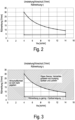
- the optimal process window for the stirring effect also depends on the welding speed V w .
- the welding wire contains a molybdenum content of 0.5 to 2% by mass.
- gap widths of 0 to 0.3 mm, in particular 0 to 0.2 mm are set.
- Setting the "technical zero gap", i.e. the sheets without a deliberate gap setting, can be particularly advantageous, as this can have process-related advantages.
- setting the gap to 0.2 mm can be advantageous for reducing the Al content in the weld seam.
- a steel is used as the base material which is a boron-manganese steel which can be hardened by an austenitizing and quenching process to a tensile strength of more than 900 MPa, and in particular a steel from the group of CMnB steels such as 22MnB5 or 20MnB8 is used.
- the base material is a steel with the general alloy composition (in mass%) Carbon (C) 0.03-0.6 Manganese (Mn) 0.3-3.0 Aluminium (Al) 0.01-0.07 Silicon (Si) 0.01-0.8 Chromium (Cr) 0.02-0.6 Nickel (Ni) ⁇ 0.5 Titanium (Ti) 0.01-0.08 Niobium (Nb) ⁇ 0.1 Nitrogen (N) ⁇ 0.02 Boron (B) ⁇ 0.02 Phosphorus (P) ⁇ 0.01 Sulfur (S) ⁇ 0.01 Molybdenum (Mo) ⁇ 1
- the base material can be a steel of the general alloy composition (in mass %) Carbon (C) 0.03-0.36 Manganese (Mn) 0.3-2.00 Aluminium (Al) 0.03-0.06 Silicon (Si) 0.01-0.20 Chromium (Cr) 0.02-0.4 Nickel (Ni) ⁇ 0.5 Titanium (Ti) 0.03-0.04 Niobium (Nb) ⁇ 0.1 Nitrogen (N) ⁇ 0.007 Boron (B) ⁇ 0.006 Phosphorus (P) ⁇ 0.01 Sulfur (S) ⁇ 0.01 Molybdenum (Mo) ⁇ 1
- the additional wire has a carbon content in the range of 0.024 to 1.086 mass%, particularly preferably 0.186 to 0.5082 mass%, even more preferably between 0.20 to 0.257 mass%.
- the steel sheets have a different alloy composition.
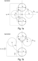
- FIG. 1 Three different laser beam configurations are shown, which are possible in principle and can also be combined with each other, whereby the laser beam configurations shown are in a symmetrical configuration ( Fig. 1a ), the laser beams are arranged symmetrically to a rotation axis and are rotated diametrically opposite each other around the rotation axis.
- the symmetrical configuration can advantageously achieve the highest stirring effect.
- one laser beam is positioned closer to the axis of rotation than the other, creating eccentricity.
- the asymmetrical arrangement can advantageously influence the desired weld geometry.
- the orbital arrangement can advantageously have a compensating effect on any differences in sheet thickness.
- this laser beam configuration 1 there are two laser beams 2, 3, each of which is approximately the same distance from an idealized weld pool center 4.
- the rotation axis 5, around which the two laser beams 2, 3 rotate according to the rotation directions 6, 7, is also located in the ideal weld pool center 4.
- exemplary subsequent positions 2', 3' offset by 90° are shown.
- the laser beams 2, 3 or their projection surface (spot) have a given diameter df according to the expansion arrows 8, 9.
- the two laser beams 2, 3 and their projection surfaces (spots) are each spaced apart from the center by the spot distance X df .
- the theoretical weld pool width is therefore the spot distance plus half the spot diameter.
- the welding progress takes place according to the arrow 10 along the idealized weld pool center 4 with a welding progress speed V w .
- the spot diameter df is preferably within a range of 0.1 to 1 mm.
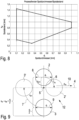
- the distance between the spot centers plus the spot diameter is preferably between 0.5 mm and 3 mm, in particular 0.9 mm to 2.5 mm, whereby the spot distance x df preferably has the value x df ⁇ 0.8 * df.
- a suitable process window for the symmetrical stirring arrangement concerning the relationship between spot distance and diameter can be seen in Figure 6 As already mentioned, the rule is that the spot diameter df is between 0.1 and 1 mm.
- two laser beams 2, 3 are arranged orbitally, which means that a first spot 2 remains on the welding axis 4 according to the welding progress direction 10, while a second spot 3 rotates about a rotation axis 5 which lies on the welding axis 4 and represents the center of the first spot 2.
- the rotation of the second spot 3 takes place accordingly along the rotation direction 7, which is arranged in a certain radius around the rotation axis 5.
- the different positions of the second laser spot 3 are in Figure 7 shown as an example rotated by 180° with the position 3'. However, complete rotations are carried out during welding along the welding progress 10.
- the welding axis 4 is also the idealized weld pool center 4.
- the spot diameter is also between 0.1 and 1 mm, whereby: 0.45 mm ⁇ x df + d e 2 ⁇ 1.5 mm
- two laser spots 2, 3 rotate about a rotation axis 5, whereby a first rotation direction 6 of a first laser beam 2 or first laser spot 2 is arranged closer to the rotation axis than the second rotation direction 7 of the second laser beam 2.
- the spot distance center is thus arranged away from the weld pool center 4 or offset from it.
- the spot diameter df is again between 0.1 and 1 mm, whereby the following condition is also met: X df ⁇ 0.8 ⁇ d e 0.45 mm ⁇ x df ⁇ xoff + d e 2 ⁇ 1.5 mm 0 ⁇ x off ⁇ xdf 2
- a laser welding speed (v w ) of less than 4 m/min is technically possible but no longer economically viable.
- FIG 10 a weld structure after hardening is shown (example V1 from the table in Fig.4 ) in which the parameters according to the invention were not adhered to.
- the weld seam structure after hardening is visually perceptible as inhomogeneous, whereby the welding progress rate was 6 m per minute.
- the spot diameter was 0.3 mm, but with a spot distance of 0, which means that only a single laser was used. It is clear that a qualitatively satisfactory result cannot be achieved with this conventional method.
- Figure 11 is the result of an embodiment according to the invention (example V2 from the table in Fig.4 ), whereby the grinding is homogeneous after hardening.
- the spot diameter here was 0.3 mm, whereby a symmetrical stirring arrangement was used with a spot spacing of 0.9 mm.
- the laser power was 4.3 kW and the welding progress speed was 6 m per minute.
- the stirring effect ⁇ was 4.125 mm -1 , where the stirring effect is the quotient of the rotation frequency and the welding speed or welding progress.
- the distance of the spot center to the rotation axis was 0.45 mm, which means that the spots orbited the rotation axis on a radius.
- Test 4 is shown, which is not in accordance with the invention. While the spot diameter and the spot spacing are in a range in accordance with the invention, as is the welding progress speed, which at 6 m per minute corresponds to that of test 2, the distance of the spot center to the rotation axis is also the same, but the stirring effect as a quotient of the rotation frequency and welding progress speed is too low, so that the grinding after hardening shows a clear inhomogeneity.
- FIG 13 the result of the test 16 according to the invention is shown. It can be seen that a homogeneous weld seam structure is present.
- the spot distance is 0.4 mm with a spot diameter of 0.3 mm, whereby the progress speed corresponds to that of the other tests.
- the stirring effect ⁇ is 4.125 mm -1 in the range according to the invention, whereby the distance of the spot center to the axis of rotation was 0.2 mm.
- the advantage of the invention is that through a targeted selection of parameters and appropriate process control, reliably homogeneous weld seams can be achieved when welding aluminum-silicon coated sheets.
- CMn steels in particular a hardenable CMnB steel, in particular 22MnB5 steel materials
- a welding filler wire In particular, according to the invention, aluminum-silicon-coated steel sheets with > 900 MPa tensile strength after hardening are joined by welding without ablation.
- C 0.90 to 1.26 ⁇ C base material
- the materials used are aluminum-silicon coated sheets with a coating of 60g/m 2 per side made of 22MnB5, whereby sheets with a thickness of 1.5 mm were joined for the purpose of tensile tests.
- Such sheets were provided with welding edges and welded with a Trumpf welding laser 4006 (4.4 kW) with a focus size diameter of 0.6 mm.
- the base material is a steel of the general alloy composition (in mass%) Carbon (C) 0.03-0.6 Manganese (Mn) 0.3-3.0 Aluminium (Al) 0.01-0.07 Silicon (Si) 0.01-0.8 Chromium (Cr) 0.02-0.6 Nickel (Ni) ⁇ 0.5 Titanium (Ti) 0.01-0.08 Niobium (Nb) ⁇ 0.1 Nitrogen (N) ⁇ 0.02 Boron (B) 0.002-0.02 Phosphorus (P) ⁇ 0.01 Sulfur (S) ⁇ 0.01 Molybdenum (Mo) ⁇ 1
- the carbon content of the filler wire can range from 0.024 to 1.086 mass%.
- the carbon content of the additional wire is of course selected specifically based on the carbon content of the base material.
- the base material may have the following alloy composition: Carbon (C) 0.03-0.36 Manganese (Mn) 0.3-2.00 Aluminium (Al) 0.03-0.06 Silicon (Si) 0.01-0.20 Chromium (Cr) 0.02-0.4 Nickel (Ni) ⁇ 0.5 Titanium (Ti) 0.03-0.04 Niobium (Nb) ⁇ 0.1 Nitrogen (N) ⁇ 0.007 Boron (B) 0.002-0.006 Phosphorus (P) ⁇ 0.01 Sulfur (S) ⁇ 0.01 Molybdenum (Mo) ⁇ 1
- the carbon content of the additional wire can be in the range of 0.186 to 0.5082 mass% or particularly preferably between 0.216 to 0.257 mass%.
Landscapes
- Engineering & Computer Science (AREA)
- Physics & Mathematics (AREA)
- Optics & Photonics (AREA)
- Mechanical Engineering (AREA)
- Plasma & Fusion (AREA)
- Laser Beam Processing (AREA)
Claims (18)
- Procédé de soudage de tôles d'acier revêtues, en particulier des tôles d'acier revêtues avec une couche de revêtement métallique à base d'aluminium-silicium, dans lequel existe une configuration (1, 11, 12) de deux faisceaux laser (2, 3), dans lequel les faisceaux laser agissent sur un bain de fusion à former, dans lequel au moins un faisceau laser (3) tourne autour d'un axe de rotation (5) de sorte que les faisceaux laser (2, 3) effectuent un mouvement relatif l'un par rapport à l'autre, dans lequel les faisceaux laser (2, 3) sont guidés le long d'un axe de soudage (4), dans lequel un effet d'agitation défini et une vitesse de soudage définie sont maintenus en fonction l'un de l'autre afin d'obtenir le mélange du bain de fusion, dans lequel l'équation suivante s'applique pour l'effet d'agitation :


C = 0,80 à 2,28 x % C, matériau de base Cr = 8à20% Ni < 5 % Si = 0,2 à 3 % Mn = 0,2 à 1 % en option Mo < 2 % en option V et/ou W au total < 1 % - Procédé selon la revendication 1,
caractérisé en ce que,
les faisceaux laser (2, 3) tournent de manière diamétralement opposée autour d'un axe de rotation en étant agencés de manière symétrique autour dudit axe de rotation (5), ou un faisceau laser (2) est guidé le long d'un axe de soudage (4) et l'autre faisceau laser (3) tourne autour du premier faisceau laser (2), ou un premier faisceau laser (2) tourne autour de l'axe de rotation (5) avec un premier rayon inférieur tandis que le deuxième faisceau de soudage tourne autour de l'axe de rotation. (5) avec un rayon supérieur, ou un mélange desdites formes de mouvement. - Procédé selon l'une des revendications précédentes,
caractérisé en ce que,
lors d'une rotation symétrique des faisceaux laser (2, 3) ou de leurs surfaces de projection ou points, les faisceaux laser (2, 3) sont espacés respectivement par rapport au centre de la distance de point Xdf, le diamètre de point ou le diamètre du faisceau laser df étant compris entre 0,1 mm et 1 mm, la largeur de couverture totale des faisceaux laser (2, 3) étant la distance entre les centres de point à laquelle on ajoute un diamètre de point, ladite largeur étant comprise entre 0,5 mm et 2,5 mm. - Procédé selon la revendication 3,
caractérisé en ce que,
pour la distance de point Xdf, Xdf ≥ 0,8 * df s'applique. - Procédé selon la revendication 2,
caractérisé en ce que,
dans une configuration de faisceau laser (11), deux faisceaux laser (2, 3) sont agencés de manière orbitale, un premier faisceau laser (3) demeurant le long de la direction de progression du soudage (10) sur un axe central du bain de fusion, à savoir l'axe de soudage (4), tandis que le deuxième faisceau laser (3) ou deuxième point (3) tourne autour d'un axe de rotation (5), où l'axe de rotation (5) se trouve sur l'axe de soudage (4) ou oscille autour de l'axe de soudage (4) et représente le centre du premier point (2). - Procédé selon la revendication 5,
caractérisé en ce que,
le diamètre du point est compris entre 0,1 et 1 mm, où :

- Procédé selon la revendication 2,
caractérisé en ce que,
dans une configuration de faisceau laser (12), deux faisceaux laser (2, 3) ou deux points laser (2, 3) tournent autour d'un axe de rotation (5), un premier faisceau laser (2) ou un premier point laser (2) tournant autour de l'axe de rotation (5) avec un premier rayon, et le deuxième faisceau laser (3) ou le deuxième point laser (3) tournant autour de l'axe de rotation (5) avec un deuxième rayon, où un des rayons est supérieur à l'autre, et où les conditions ci-après s'appliquent :


- Procédé selon l'une quelconque des revendications précédentes,
caractérisé en ce que,
le soudage est réalisé avec une puissance laser comprise entre 2 et 10 kW, en particulier comprise entre 3 et 8 kW, de manière préférée comprise entre 4 et 7 kW. - Procédé selon l'une des revendications précédentes,
caractérisé en ce que,
l'effet d'agitation η, en mm-1, est compris entre 4 et 30 mm-1. - Procédé selon l'une des revendications précédentes,
caractérisé en ce que,
la vitesse de soudage vw est comprise entre 5 et 12, en particulier entre 6 et 10 m/min. - Procédé selon la revendication 1, caractérisé en ce qu'on utilise un fil de soudure dont la teneur en nickel est inférieure à 1 % en masse.
- Procédé selon la revendication 1,
caractérisé en ce que,
le fil de soudure présente une teneur en molybdène comprise entre 0,5 et 2 % en masse. - Procédé selon l'une des revendications précédentes, caractérisé en ce que l'on règle des largeurs d'intervalle comprises entre 0 et 0,3 mm, en particulier comprises entre 0 et 0,1 mm.
- Procédé selon l'une des revendications précédentes, caractérisé en ce que l'on règle la teneur en carbone du fil d'apport àC = 0,88 à 1,51 × C, matériau de base,de préférenceC = 0,90 à 1,26 × C, matériau de base,de manière particulièrement préféréeC = 0,90 à 1,17 × C, matériau de base.
- Procédé selon l'une des revendications précédentes,
caractérisé en ce que,
l'on utilise comme matériau de base un acier, qui est un acier au bore-manganèse qui peut être durci grâce à un procédé d'austénitisation et de trempe jusqu'à une résistance à la traction de manière particulièrement préférée supérieure à 900 MPa, et en particulier un acier du groupe des aciers CMnB tel que du 22MnB5 ou du 20MnB8. - Procédé selon l'une des revendications précédentes,
caractérisé en ce que,
l'on utilise comme matériau de base un acier de composition générale d'alliage suivante (% en masse) :Carbone (C) 0,03 à 0,6 Manganèse ( Mn ) 0,3 à 3,0 Aluminium (Al) 0,01 à 0,07 Silicium (Si) 0,01 à 0,8 Chrome ( Cr ) 0,02 à 0,6 Nickel (Ni) < 0,5 Titane (Ti) 0,01 à 0,08 Niobium (Nb) < 0,1 Azote (N) < 0,02 Bore (B) < 0,02 Phosphore (P) < 0,01 Soufre (S) < 0,01 Molybdène (Mo) < 1 - Procédé selon l'une des revendications précédentes,
caractérisé en ce que,
l'on utilise comme matériau de base un acier de composition générale d'alliage suivante (% en masse) :Carbone (C) 0,03 à 0,36 Manganèse ( Mn ) 0,3 à 2,00 Aluminium (Al) 0,03 à 0,06 Silicium (Si) 0,01 à 0,20 Chrome ( Cr ) 0,02 à 0,4 Nickel (Ni) < 0,5 Titane (Ti) 0,03 à 0,04 Niobium (Nb) < 0,1 Azote (N) < 0,007 Bore (B) < 0,006 Phosphore (P) < 0,01 Soufre (S) < 0,01 Molybdène (Mo) < 1 - Procédé selon l'une des revendications précédentes,
caractérisé en ce que,
le fil d'apport présente une teneur en carbone située dans la plage comprise entre 0,024 et 1,086 % en masse, de manière particulièrement préférée entre 0,186 et 0,5082 % en masse, de manière plus particulièrement préférée entre 0,20 et 0,257 % en masse.
Applications Claiming Priority (2)
| Application Number | Priority Date | Filing Date | Title |
|---|---|---|---|
| DE102019131908.0A DE102019131908A1 (de) | 2019-11-26 | 2019-11-26 | Verfahren zum Verschweißen beschichteter Stahlbleche |
| PCT/EP2020/083526 WO2021105294A1 (fr) | 2019-11-26 | 2020-11-26 | Procédé pour souder des tôles d'acier revêtues |
Publications (3)
| Publication Number | Publication Date |
|---|---|
| EP4065306A1 EP4065306A1 (fr) | 2022-10-05 |
| EP4065306B1 true EP4065306B1 (fr) | 2024-09-25 |
| EP4065306C0 EP4065306C0 (fr) | 2024-09-25 |
Family
ID=73646310
Family Applications (1)
| Application Number | Title | Priority Date | Filing Date |
|---|---|---|---|
| EP20816430.1A Active EP4065306B1 (fr) | 2019-11-26 | 2020-11-26 | Procédé pour souder des tôles d'acier revêtues |
Country Status (7)
| Country | Link |
|---|---|
| US (1) | US20220410314A1 (fr) |
| EP (1) | EP4065306B1 (fr) |
| KR (1) | KR102647717B1 (fr) |
| CN (1) | CN115175781B (fr) |
| DE (1) | DE102019131908A1 (fr) |
| MX (1) | MX2022006244A (fr) |
| WO (1) | WO2021105294A1 (fr) |
Families Citing this family (2)
| Publication number | Priority date | Publication date | Assignee | Title |
|---|---|---|---|---|
| DE102019131906A1 (de) * | 2019-11-26 | 2021-05-27 | Voestalpine Automotive Components Linz Gmbh | Verfahren zum Verschweißen beschichteter Stahlbleche |
| CN113732499A (zh) * | 2021-10-09 | 2021-12-03 | 上海科技大学 | 一种基于可变光斑的振镜扫描激光焊接方法 |
Family Cites Families (28)
| Publication number | Priority date | Publication date | Assignee | Title |
|---|---|---|---|---|
| CA2335546A1 (fr) * | 1998-06-29 | 2000-01-06 | Automated Welding Systems Inc. | Procede pour souder au laser des ebauches specialement adaptees |
| JP3576472B2 (ja) * | 1999-12-28 | 2004-10-13 | Jfeスチール株式会社 | 低炭素マルテンサイト系ステンレス鋼用溶接材料および低炭素マルテンサイト系ステンレス鋼材のアーク溶接方法 |
| JP4358407B2 (ja) * | 2000-05-17 | 2009-11-04 | 新日本製鐵株式会社 | レーザー溶接性に優れた厚鋼板の溶接方法 |
| JP2004001084A (ja) | 2002-03-28 | 2004-01-08 | Ishikawajima Harima Heavy Ind Co Ltd | ツインスポットレーザ溶接方法及び装置 |
| KR20080017057A (ko) * | 2005-06-29 | 2008-02-25 | 코닌클리케 필립스 일렉트로닉스 엔.브이. | 레이저 용접 시스템과 방법 |
| WO2007118939A1 (fr) | 2006-04-19 | 2007-10-25 | Arcelor France | Procede de fabrication d'une piece soudee a tres hautes caracteristiques mecaniques a partir d'une tole laminee et revetue |
| FR2903623B1 (fr) | 2006-07-12 | 2008-09-19 | L'air Liquide | Procede de soudage hybride laser-arc de pieces metalliques aluminiees |
| US20130327749A1 (en) * | 2009-01-13 | 2013-12-12 | Lincoln Global Inc. | Method and system to start and use combination filler wire feed and high intensity energy source for welding aluminum to steel |
| CN103764310B (zh) * | 2011-09-01 | 2015-09-30 | 株式会社神户制钢所 | 热压成形品及其制造方法 |
| DE102012111118B3 (de) | 2012-11-19 | 2014-04-03 | Wisco Tailored Blanks Gmbh | Verfahren zum Laserschweißen eines oder mehrerer Werkstücke aus härtbarem Stahl im Stumpfstoß |
| KR101448473B1 (ko) | 2012-12-03 | 2014-10-10 | 현대하이스코 주식회사 | 테일러 웰디드 블랭크, 그 제조방법 및 이를 이용한 핫스탬핑 부품 |
| DE102013101953A1 (de) * | 2013-02-27 | 2014-08-28 | Wisco Lasertechnik Gmbh | Verfahren zum Aneinanderfügen von mit einer metallischen Beschichtung versehenen Platinen oder Bändern aus Stahl durch Laserstrahlschweißen |
| US10328513B2 (en) * | 2013-05-31 | 2019-06-25 | General Electric Company | Welding process, welding system, and welded article |
| JP2015047638A (ja) * | 2013-09-04 | 2015-03-16 | 株式会社最新レーザ技術研究センター | ビーム分岐回転光学系を用いたレーザ加工法 |
| EP2883646B1 (fr) | 2013-12-12 | 2016-11-02 | Autotech Engineering, A.I.E. | Procédés d'assemblage de deux flancs, flancs et produits obtenus |
| DE102014001979A1 (de) | 2014-02-17 | 2015-08-20 | Wisco Tailored Blanks Gmbh | Verfahren zum Laserschweißen eines oder mehrerer Werkstücke aus härtbarem Stahl im Stumpfstoß |
| WO2015162445A1 (fr) * | 2014-04-25 | 2015-10-29 | Arcelormittal Investigación Y Desarrollo Sl | Procede et dispositif de preparation de toles d'acier aluminiees destinees a etre soudees puis durcies sous presse; flan soude correspondant |
| EP2942143B1 (fr) | 2014-05-09 | 2017-03-15 | Gestamp HardTech AB | Procédés d'assemblage de deux flancs, flancs et produits obtenus |
| DE102014107716B3 (de) | 2014-06-02 | 2015-06-25 | Scansonic Mi Gmbh | Laserstrahlschweißverfahren |
| DE102015106339B4 (de) * | 2015-04-24 | 2017-02-23 | Kirchhoff Automotive Deutschland Gmbh | Verfahren zum stirnseitigen Laserschweißen der Stöße von zwei aneinandergrenzend gehaltenen Fügeflanschen |
| KR102704154B1 (ko) * | 2015-12-18 | 2024-09-09 | 오토테크 엔지니어링 에스.엘. | 2개의 블랭크를 접합하기 위한 방법 및 획득되는 블랭크 및 제품 |
| JP6863050B2 (ja) * | 2017-04-28 | 2021-04-21 | トヨタ自動車株式会社 | レーザ溶接方法及びレーザ溶接装置 |
| EP3441178A1 (fr) * | 2017-08-09 | 2019-02-13 | Autotech Engineering A.I.E. | Procédé d'assemblage de deux ébauches |
| DE102017120051B4 (de) | 2017-08-31 | 2023-01-12 | Baosteel Tailored Blanks Gmbh | Verfahren zum Laserstrahlschweißen eines oder mehrerer Stahlbleche aus presshärtbarem Mangan-Borstahl |
| WO2019102255A1 (fr) * | 2017-11-24 | 2019-05-31 | Arcelormittal | Procédé de fabrication d'une ébauche en acier soudée avec fourniture d'un fil de remplissage ayant une teneur en carbone définie, ébauche soudée associée, procédé de fabrication d'une pièce soudée avec pièce en acier formée par pressage à chaud et refroidie et pièce associée |
| DE102018107291B4 (de) * | 2018-03-27 | 2025-11-06 | Voestalpine Automotive Components Linz Gmbh | Verfahren zum Schweißen beschichteter Stahlbleche |
| CN110170742B (zh) * | 2019-06-25 | 2020-07-31 | 华中科技大学 | 一种铝合金中厚板激光焊接装置及方法 |
| DE102019131906A1 (de) * | 2019-11-26 | 2021-05-27 | Voestalpine Automotive Components Linz Gmbh | Verfahren zum Verschweißen beschichteter Stahlbleche |
-
2019
- 2019-11-26 DE DE102019131908.0A patent/DE102019131908A1/de active Pending
-
2020
- 2020-11-26 US US17/780,070 patent/US20220410314A1/en active Pending
- 2020-11-26 KR KR1020227021632A patent/KR102647717B1/ko active Active
- 2020-11-26 MX MX2022006244A patent/MX2022006244A/es unknown
- 2020-11-26 CN CN202080091667.0A patent/CN115175781B/zh active Active
- 2020-11-26 WO PCT/EP2020/083526 patent/WO2021105294A1/fr not_active Ceased
- 2020-11-26 EP EP20816430.1A patent/EP4065306B1/fr active Active
Also Published As
| Publication number | Publication date |
|---|---|
| CN115175781A (zh) | 2022-10-11 |
| DE102019131908A1 (de) | 2021-05-27 |
| WO2021105294A9 (fr) | 2021-07-15 |
| MX2022006244A (es) | 2022-08-08 |
| KR102647717B1 (ko) | 2024-03-13 |
| US20220410314A1 (en) | 2022-12-29 |
| EP4065306A1 (fr) | 2022-10-05 |
| CN115175781B (zh) | 2025-09-23 |
| WO2021105294A1 (fr) | 2021-06-03 |
| CA3162879A1 (fr) | 2021-06-03 |
| EP4065306C0 (fr) | 2024-09-25 |
| KR20230002269A (ko) | 2023-01-05 |
Similar Documents
| Publication | Publication Date | Title |
|---|---|---|
| EP3352940B1 (fr) | Procédé de soudage par laser pour la production d'une plaque semi-finie en acier durcissable avec un revetement basé sur aluminium ou aluminium-silicium | |
| EP3676047B1 (fr) | Procédé pour le soudage laser d'une ou de plusieurs tôles d'acier constituées d'acier au bore et au manganèse pouvant être embouti à chaud | |
| EP3774167B1 (fr) | Procédé de soudage de plaques d'acier revetues | |
| AT16699U2 (de) | Verfahren zur Bereitstellung von Aluminium-beschichteten Stahlblechen | |
| DE102012111118B3 (de) | Verfahren zum Laserschweißen eines oder mehrerer Werkstücke aus härtbarem Stahl im Stumpfstoß | |
| EP3946801B1 (fr) | Procédé de soudage par fusion d'une ou plusieurs tôles d'acier en acier emboutissable à chaud | |
| WO2015121074A1 (fr) | Procédé de soudage au laser d'une ou de plusieurs pièces en acier pouvant être trempé dans une jonction bout à bout | |
| EP4065307B1 (fr) | Procédé de soudage de tôles d'acier revêtues | |
| DE202019005926U1 (de) | Schweißvorbehandeltes beschichtetes Stahlblech | |
| EP3996867A1 (fr) | Procédé de fabrication d'une plaque coupée sur mesure revêtue, par soudage par faisceau laser ou soudage hybride laser à gaz protecteur de métal, et fil d'apport ainsi qu'utilisation de ce dernier s'y rapportant | |
| EP4065306B1 (fr) | Procédé pour souder des tôles d'acier revêtues | |
| EP3600755B1 (fr) | Procédé de soudage au laser côté frontal | |
| WO2022128614A1 (fr) | Procédé de production d'une liaison articulée et pièces en tôle reliées de manière correspondante | |
| CA3162879C (fr) | Procédé pour souder des tôles d’acier revêtues | |
| EP4613417A1 (fr) | Procédé de fabrication d'une feuille pliée |
Legal Events
| Date | Code | Title | Description |
|---|---|---|---|
| STAA | Information on the status of an ep patent application or granted ep patent |
Free format text: STATUS: UNKNOWN |
|
| STAA | Information on the status of an ep patent application or granted ep patent |
Free format text: STATUS: THE INTERNATIONAL PUBLICATION HAS BEEN MADE |
|
| PUAI | Public reference made under article 153(3) epc to a published international application that has entered the european phase |
Free format text: ORIGINAL CODE: 0009012 |
|
| STAA | Information on the status of an ep patent application or granted ep patent |
Free format text: STATUS: REQUEST FOR EXAMINATION WAS MADE |
|
| 17P | Request for examination filed |
Effective date: 20220601 |
|
| AK | Designated contracting states |
Kind code of ref document: A1 Designated state(s): AL AT BE BG CH CY CZ DE DK EE ES FI FR GB GR HR HU IE IS IT LI LT LU LV MC MK MT NL NO PL PT RO RS SE SI SK SM TR |
|
| DAV | Request for validation of the european patent (deleted) | ||
| DAX | Request for extension of the european patent (deleted) | ||
| P01 | Opt-out of the competence of the unified patent court (upc) registered |
Effective date: 20230706 |
|
| STAA | Information on the status of an ep patent application or granted ep patent |
Free format text: STATUS: EXAMINATION IS IN PROGRESS |
|
| 17Q | First examination report despatched |
Effective date: 20231024 |
|
| GRAP | Despatch of communication of intention to grant a patent |
Free format text: ORIGINAL CODE: EPIDOSNIGR1 |
|
| STAA | Information on the status of an ep patent application or granted ep patent |
Free format text: STATUS: GRANT OF PATENT IS INTENDED |
|
| INTG | Intention to grant announced |
Effective date: 20240422 |
|
| GRAS | Grant fee paid |
Free format text: ORIGINAL CODE: EPIDOSNIGR3 |
|
| GRAA | (expected) grant |
Free format text: ORIGINAL CODE: 0009210 |
|
| STAA | Information on the status of an ep patent application or granted ep patent |
Free format text: STATUS: THE PATENT HAS BEEN GRANTED |
|
| AK | Designated contracting states |
Kind code of ref document: B1 Designated state(s): AL AT BE BG CH CY CZ DE DK EE ES FI FR GB GR HR HU IE IS IT LI LT LU LV MC MK MT NL NO PL PT RO RS SE SI SK SM TR |
|
| REG | Reference to a national code |
Ref country code: GB Ref legal event code: FG4D Free format text: NOT ENGLISH |
|
| REG | Reference to a national code |
Ref country code: CH Ref legal event code: EP |
|
| REG | Reference to a national code |
Ref country code: DE Ref legal event code: R096 Ref document number: 502020009343 Country of ref document: DE |
|
| REG | Reference to a national code |
Ref country code: IE Ref legal event code: FG4D Free format text: LANGUAGE OF EP DOCUMENT: GERMAN |
|
| U01 | Request for unitary effect filed |
Effective date: 20241010 |
|
| P04 | Withdrawal of opt-out of the competence of the unified patent court (upc) registered |
Free format text: CASE NUMBER: APP_58613/2024 Effective date: 20241026 |
|
| U07 | Unitary effect registered |
Designated state(s): AT BE BG DE DK EE FI FR IT LT LU LV MT NL PT RO SE SI Effective date: 20241030 |
|
| U20 | Renewal fee for the european patent with unitary effect paid |
Year of fee payment: 5 Effective date: 20241127 |
|
| PG25 | Lapsed in a contracting state [announced via postgrant information from national office to epo] |
Ref country code: NO Free format text: LAPSE BECAUSE OF FAILURE TO SUBMIT A TRANSLATION OF THE DESCRIPTION OR TO PAY THE FEE WITHIN THE PRESCRIBED TIME-LIMIT Effective date: 20241225 |
|
| PG25 | Lapsed in a contracting state [announced via postgrant information from national office to epo] |
Ref country code: GR Free format text: LAPSE BECAUSE OF FAILURE TO SUBMIT A TRANSLATION OF THE DESCRIPTION OR TO PAY THE FEE WITHIN THE PRESCRIBED TIME-LIMIT Effective date: 20241226 |
|
| PG25 | Lapsed in a contracting state [announced via postgrant information from national office to epo] |
Ref country code: RS Free format text: LAPSE BECAUSE OF FAILURE TO SUBMIT A TRANSLATION OF THE DESCRIPTION OR TO PAY THE FEE WITHIN THE PRESCRIBED TIME-LIMIT Effective date: 20241225 |
|
| PG25 | Lapsed in a contracting state [announced via postgrant information from national office to epo] |
Ref country code: RS Free format text: LAPSE BECAUSE OF FAILURE TO SUBMIT A TRANSLATION OF THE DESCRIPTION OR TO PAY THE FEE WITHIN THE PRESCRIBED TIME-LIMIT Effective date: 20241225 Ref country code: NO Free format text: LAPSE BECAUSE OF FAILURE TO SUBMIT A TRANSLATION OF THE DESCRIPTION OR TO PAY THE FEE WITHIN THE PRESCRIBED TIME-LIMIT Effective date: 20241225 Ref country code: GR Free format text: LAPSE BECAUSE OF FAILURE TO SUBMIT A TRANSLATION OF THE DESCRIPTION OR TO PAY THE FEE WITHIN THE PRESCRIBED TIME-LIMIT Effective date: 20241226 |
|
| PG25 | Lapsed in a contracting state [announced via postgrant information from national office to epo] |
Ref country code: IS Free format text: LAPSE BECAUSE OF FAILURE TO SUBMIT A TRANSLATION OF THE DESCRIPTION OR TO PAY THE FEE WITHIN THE PRESCRIBED TIME-LIMIT Effective date: 20250125 |
|
| PG25 | Lapsed in a contracting state [announced via postgrant information from national office to epo] |
Ref country code: SM Free format text: LAPSE BECAUSE OF FAILURE TO SUBMIT A TRANSLATION OF THE DESCRIPTION OR TO PAY THE FEE WITHIN THE PRESCRIBED TIME-LIMIT Effective date: 20240925 |
|
| PG25 | Lapsed in a contracting state [announced via postgrant information from national office to epo] |
Ref country code: ES Free format text: LAPSE BECAUSE OF FAILURE TO SUBMIT A TRANSLATION OF THE DESCRIPTION OR TO PAY THE FEE WITHIN THE PRESCRIBED TIME-LIMIT Effective date: 20240925 |
|
| PG25 | Lapsed in a contracting state [announced via postgrant information from national office to epo] |
Ref country code: PL Free format text: LAPSE BECAUSE OF FAILURE TO SUBMIT A TRANSLATION OF THE DESCRIPTION OR TO PAY THE FEE WITHIN THE PRESCRIBED TIME-LIMIT Effective date: 20240925 Ref country code: CZ Free format text: LAPSE BECAUSE OF FAILURE TO SUBMIT A TRANSLATION OF THE DESCRIPTION OR TO PAY THE FEE WITHIN THE PRESCRIBED TIME-LIMIT Effective date: 20240925 |
|
| PG25 | Lapsed in a contracting state [announced via postgrant information from national office to epo] |
Ref country code: SK Free format text: LAPSE BECAUSE OF FAILURE TO SUBMIT A TRANSLATION OF THE DESCRIPTION OR TO PAY THE FEE WITHIN THE PRESCRIBED TIME-LIMIT Effective date: 20240925 |
|
| REG | Reference to a national code |
Ref country code: CH Ref legal event code: PL |
|
| PG25 | Lapsed in a contracting state [announced via postgrant information from national office to epo] |
Ref country code: MC Free format text: LAPSE BECAUSE OF FAILURE TO SUBMIT A TRANSLATION OF THE DESCRIPTION OR TO PAY THE FEE WITHIN THE PRESCRIBED TIME-LIMIT Effective date: 20240925 |
|
| REG | Reference to a national code |
Ref country code: CH Ref legal event code: PL |
|
| PG25 | Lapsed in a contracting state [announced via postgrant information from national office to epo] |
Ref country code: CH Free format text: LAPSE BECAUSE OF NON-PAYMENT OF DUE FEES Effective date: 20241130 |
|
| PLBE | No opposition filed within time limit |
Free format text: ORIGINAL CODE: 0009261 |
|
| STAA | Information on the status of an ep patent application or granted ep patent |
Free format text: STATUS: NO OPPOSITION FILED WITHIN TIME LIMIT |
|
| GBPC | Gb: european patent ceased through non-payment of renewal fee |
Effective date: 20241225 |
|
| 26N | No opposition filed |
Effective date: 20250626 |
|
| PG25 | Lapsed in a contracting state [announced via postgrant information from national office to epo] |
Ref country code: GB Free format text: LAPSE BECAUSE OF NON-PAYMENT OF DUE FEES Effective date: 20241225 |
|
| PG25 | Lapsed in a contracting state [announced via postgrant information from national office to epo] |
Ref country code: IE Free format text: LAPSE BECAUSE OF NON-PAYMENT OF DUE FEES Effective date: 20241126 |
|
| U20 | Renewal fee for the european patent with unitary effect paid |
Year of fee payment: 6 Effective date: 20251126 |
|
| PG25 | Lapsed in a contracting state [announced via postgrant information from national office to epo] |
Ref country code: HR Free format text: LAPSE BECAUSE OF FAILURE TO SUBMIT A TRANSLATION OF THE DESCRIPTION OR TO PAY THE FEE WITHIN THE PRESCRIBED TIME-LIMIT Effective date: 20240925 |
|
| PG25 | Lapsed in a contracting state [announced via postgrant information from national office to epo] |
Ref country code: HU Free format text: LAPSE BECAUSE OF FAILURE TO SUBMIT A TRANSLATION OF THE DESCRIPTION OR TO PAY THE FEE WITHIN THE PRESCRIBED TIME-LIMIT; INVALID AB INITIO Effective date: 20201126 |
|
| PG25 | Lapsed in a contracting state [announced via postgrant information from national office to epo] |
Ref country code: CY Free format text: LAPSE BECAUSE OF FAILURE TO SUBMIT A TRANSLATION OF THE DESCRIPTION OR TO PAY THE FEE WITHIN THE PRESCRIBED TIME-LIMIT; INVALID AB INITIO Effective date: 20201126 |