EP4065348B1 - Fixation solide d'un second objet à un premier objet - Google Patents
Fixation solide d'un second objet à un premier objet Download PDFInfo
- Publication number
- EP4065348B1 EP4065348B1 EP20811659.0A EP20811659A EP4065348B1 EP 4065348 B1 EP4065348 B1 EP 4065348B1 EP 20811659 A EP20811659 A EP 20811659A EP 4065348 B1 EP4065348 B1 EP 4065348B1
- Authority
- EP
- European Patent Office
- Prior art keywords
- indentation
- layer
- building
- building layer
- sidewall
- Prior art date
- Legal status (The legal status is an assumption and is not a legal conclusion. Google has not performed a legal analysis and makes no representation as to the accuracy of the status listed.)
- Active
Links
Images


Classifications
-
- B—PERFORMING OPERATIONS; TRANSPORTING
- B29—WORKING OF PLASTICS; WORKING OF SUBSTANCES IN A PLASTIC STATE IN GENERAL
- B29B—PREPARATION OR PRETREATMENT OF THE MATERIAL TO BE SHAPED; MAKING GRANULES OR PREFORMS; RECOVERY OF PLASTICS OR OTHER CONSTITUENTS OF WASTE MATERIAL CONTAINING PLASTICS
- B29B9/00—Making granules
- B29B9/10—Making granules by moulding the material, i.e. treating it in the molten state
-
- B—PERFORMING OPERATIONS; TRANSPORTING
- B29—WORKING OF PLASTICS; WORKING OF SUBSTANCES IN A PLASTIC STATE IN GENERAL
- B29C—SHAPING OR JOINING OF PLASTICS; SHAPING OF MATERIAL IN A PLASTIC STATE, NOT OTHERWISE PROVIDED FOR; AFTER-TREATMENT OF THE SHAPED PRODUCTS, e.g. REPAIRING
- B29C65/00—Joining or sealing of preformed parts, e.g. welding of plastics materials; Apparatus therefor
- B29C65/02—Joining or sealing of preformed parts, e.g. welding of plastics materials; Apparatus therefor by heating, with or without pressure
- B29C65/06—Joining or sealing of preformed parts, e.g. welding of plastics materials; Apparatus therefor by heating, with or without pressure using friction, e.g. spin welding
-
- B—PERFORMING OPERATIONS; TRANSPORTING
- B29—WORKING OF PLASTICS; WORKING OF SUBSTANCES IN A PLASTIC STATE IN GENERAL
- B29C—SHAPING OR JOINING OF PLASTICS; SHAPING OF MATERIAL IN A PLASTIC STATE, NOT OTHERWISE PROVIDED FOR; AFTER-TREATMENT OF THE SHAPED PRODUCTS, e.g. REPAIRING
- B29C65/00—Joining or sealing of preformed parts, e.g. welding of plastics materials; Apparatus therefor
- B29C65/02—Joining or sealing of preformed parts, e.g. welding of plastics materials; Apparatus therefor by heating, with or without pressure
- B29C65/06—Joining or sealing of preformed parts, e.g. welding of plastics materials; Apparatus therefor by heating, with or without pressure using friction, e.g. spin welding
- B29C65/0672—Spin welding
-
- B—PERFORMING OPERATIONS; TRANSPORTING
- B29—WORKING OF PLASTICS; WORKING OF SUBSTANCES IN A PLASTIC STATE IN GENERAL
- B29C—SHAPING OR JOINING OF PLASTICS; SHAPING OF MATERIAL IN A PLASTIC STATE, NOT OTHERWISE PROVIDED FOR; AFTER-TREATMENT OF THE SHAPED PRODUCTS, e.g. REPAIRING
- B29C65/00—Joining or sealing of preformed parts, e.g. welding of plastics materials; Apparatus therefor
- B29C65/02—Joining or sealing of preformed parts, e.g. welding of plastics materials; Apparatus therefor by heating, with or without pressure
- B29C65/08—Joining or sealing of preformed parts, e.g. welding of plastics materials; Apparatus therefor by heating, with or without pressure using ultrasonic vibrations
-
- B—PERFORMING OPERATIONS; TRANSPORTING
- B29—WORKING OF PLASTICS; WORKING OF SUBSTANCES IN A PLASTIC STATE IN GENERAL
- B29C—SHAPING OR JOINING OF PLASTICS; SHAPING OF MATERIAL IN A PLASTIC STATE, NOT OTHERWISE PROVIDED FOR; AFTER-TREATMENT OF THE SHAPED PRODUCTS, e.g. REPAIRING
- B29C65/00—Joining or sealing of preformed parts, e.g. welding of plastics materials; Apparatus therefor
- B29C65/56—Joining or sealing of preformed parts, e.g. welding of plastics materials; Apparatus therefor using mechanical means or mechanical connections, e.g. form-fits
- B29C65/562—Joining or sealing of preformed parts, e.g. welding of plastics materials; Apparatus therefor using mechanical means or mechanical connections, e.g. form-fits using extra joining elements, i.e. which are not integral with the parts to be joined
-
- B—PERFORMING OPERATIONS; TRANSPORTING
- B29—WORKING OF PLASTICS; WORKING OF SUBSTANCES IN A PLASTIC STATE IN GENERAL
- B29C—SHAPING OR JOINING OF PLASTICS; SHAPING OF MATERIAL IN A PLASTIC STATE, NOT OTHERWISE PROVIDED FOR; AFTER-TREATMENT OF THE SHAPED PRODUCTS, e.g. REPAIRING
- B29C65/00—Joining or sealing of preformed parts, e.g. welding of plastics materials; Apparatus therefor
- B29C65/56—Joining or sealing of preformed parts, e.g. welding of plastics materials; Apparatus therefor using mechanical means or mechanical connections, e.g. form-fits
- B29C65/565—Joining or sealing of preformed parts, e.g. welding of plastics materials; Apparatus therefor using mechanical means or mechanical connections, e.g. form-fits involving interference fits, e.g. force-fits or press-fits
-
- B—PERFORMING OPERATIONS; TRANSPORTING
- B29—WORKING OF PLASTICS; WORKING OF SUBSTANCES IN A PLASTIC STATE IN GENERAL
- B29C—SHAPING OR JOINING OF PLASTICS; SHAPING OF MATERIAL IN A PLASTIC STATE, NOT OTHERWISE PROVIDED FOR; AFTER-TREATMENT OF THE SHAPED PRODUCTS, e.g. REPAIRING
- B29C66/00—General aspects of processes or apparatus for joining preformed parts
- B29C66/01—General aspects dealing with the joint area or with the area to be joined
- B29C66/02—Preparation of the material, in the area to be joined, prior to joining or welding
- B29C66/022—Mechanical pre-treatments, e.g. reshaping
- B29C66/0222—Mechanical pre-treatments, e.g. reshaping without removal of material, e.g. cleaning by air blowing or using brushes
-
- B—PERFORMING OPERATIONS; TRANSPORTING
- B29—WORKING OF PLASTICS; WORKING OF SUBSTANCES IN A PLASTIC STATE IN GENERAL
- B29C—SHAPING OR JOINING OF PLASTICS; SHAPING OF MATERIAL IN A PLASTIC STATE, NOT OTHERWISE PROVIDED FOR; AFTER-TREATMENT OF THE SHAPED PRODUCTS, e.g. REPAIRING
- B29C66/00—General aspects of processes or apparatus for joining preformed parts
- B29C66/01—General aspects dealing with the joint area or with the area to be joined
- B29C66/05—Particular design of joint configurations
- B29C66/302—Particular design of joint configurations the area to be joined comprising melt initiators
- B29C66/3022—Particular design of joint configurations the area to be joined comprising melt initiators said melt initiators being integral with at least one of the parts to be joined
- B29C66/30223—Particular design of joint configurations the area to be joined comprising melt initiators said melt initiators being integral with at least one of the parts to be joined said melt initiators being rib-like
-
- B—PERFORMING OPERATIONS; TRANSPORTING
- B29—WORKING OF PLASTICS; WORKING OF SUBSTANCES IN A PLASTIC STATE IN GENERAL
- B29C—SHAPING OR JOINING OF PLASTICS; SHAPING OF MATERIAL IN A PLASTIC STATE, NOT OTHERWISE PROVIDED FOR; AFTER-TREATMENT OF THE SHAPED PRODUCTS, e.g. REPAIRING
- B29C66/00—General aspects of processes or apparatus for joining preformed parts
- B29C66/40—General aspects of joining substantially flat articles, e.g. plates, sheets or web-like materials; Making flat seams in tubular or hollow articles; Joining single elements to substantially flat surfaces
- B29C66/47—Joining single elements to sheets, plates or other substantially flat surfaces
- B29C66/474—Joining single elements to sheets, plates or other substantially flat surfaces said single elements being substantially non-flat
-
- B—PERFORMING OPERATIONS; TRANSPORTING
- B29—WORKING OF PLASTICS; WORKING OF SUBSTANCES IN A PLASTIC STATE IN GENERAL
- B29C—SHAPING OR JOINING OF PLASTICS; SHAPING OF MATERIAL IN A PLASTIC STATE, NOT OTHERWISE PROVIDED FOR; AFTER-TREATMENT OF THE SHAPED PRODUCTS, e.g. REPAIRING
- B29C66/00—General aspects of processes or apparatus for joining preformed parts
- B29C66/70—General aspects of processes or apparatus for joining preformed parts characterised by the composition, physical properties or the structure of the material of the parts to be joined; Joining with non-plastics material
- B29C66/71—General aspects of processes or apparatus for joining preformed parts characterised by the composition, physical properties or the structure of the material of the parts to be joined; Joining with non-plastics material characterised by the composition of the plastics material of the parts to be joined
-
- B—PERFORMING OPERATIONS; TRANSPORTING
- B29—WORKING OF PLASTICS; WORKING OF SUBSTANCES IN A PLASTIC STATE IN GENERAL
- B29C—SHAPING OR JOINING OF PLASTICS; SHAPING OF MATERIAL IN A PLASTIC STATE, NOT OTHERWISE PROVIDED FOR; AFTER-TREATMENT OF THE SHAPED PRODUCTS, e.g. REPAIRING
- B29C66/00—General aspects of processes or apparatus for joining preformed parts
- B29C66/70—General aspects of processes or apparatus for joining preformed parts characterised by the composition, physical properties or the structure of the material of the parts to be joined; Joining with non-plastics material
- B29C66/72—General aspects of processes or apparatus for joining preformed parts characterised by the composition, physical properties or the structure of the material of the parts to be joined; Joining with non-plastics material characterised by the structure of the material of the parts to be joined
- B29C66/721—Fibre-reinforced materials
-
- B—PERFORMING OPERATIONS; TRANSPORTING
- B29—WORKING OF PLASTICS; WORKING OF SUBSTANCES IN A PLASTIC STATE IN GENERAL
- B29C—SHAPING OR JOINING OF PLASTICS; SHAPING OF MATERIAL IN A PLASTIC STATE, NOT OTHERWISE PROVIDED FOR; AFTER-TREATMENT OF THE SHAPED PRODUCTS, e.g. REPAIRING
- B29C66/00—General aspects of processes or apparatus for joining preformed parts
- B29C66/70—General aspects of processes or apparatus for joining preformed parts characterised by the composition, physical properties or the structure of the material of the parts to be joined; Joining with non-plastics material
- B29C66/72—General aspects of processes or apparatus for joining preformed parts characterised by the composition, physical properties or the structure of the material of the parts to be joined; Joining with non-plastics material characterised by the structure of the material of the parts to be joined
- B29C66/723—General aspects of processes or apparatus for joining preformed parts characterised by the composition, physical properties or the structure of the material of the parts to be joined; Joining with non-plastics material characterised by the structure of the material of the parts to be joined being multi-layered
- B29C66/7232—General aspects of processes or apparatus for joining preformed parts characterised by the composition, physical properties or the structure of the material of the parts to be joined; Joining with non-plastics material characterised by the structure of the material of the parts to be joined being multi-layered comprising a non-plastics layer
- B29C66/72327—General aspects of processes or apparatus for joining preformed parts characterised by the composition, physical properties or the structure of the material of the parts to be joined; Joining with non-plastics material characterised by the structure of the material of the parts to be joined being multi-layered comprising a non-plastics layer consisting of natural products or their composites, not provided for in B29C66/72321 - B29C66/72324
- B29C66/72328—Paper
-
- B—PERFORMING OPERATIONS; TRANSPORTING
- B29—WORKING OF PLASTICS; WORKING OF SUBSTANCES IN A PLASTIC STATE IN GENERAL
- B29C—SHAPING OR JOINING OF PLASTICS; SHAPING OF MATERIAL IN A PLASTIC STATE, NOT OTHERWISE PROVIDED FOR; AFTER-TREATMENT OF THE SHAPED PRODUCTS, e.g. REPAIRING
- B29C66/00—General aspects of processes or apparatus for joining preformed parts
- B29C66/70—General aspects of processes or apparatus for joining preformed parts characterised by the composition, physical properties or the structure of the material of the parts to be joined; Joining with non-plastics material
- B29C66/72—General aspects of processes or apparatus for joining preformed parts characterised by the composition, physical properties or the structure of the material of the parts to be joined; Joining with non-plastics material characterised by the structure of the material of the parts to be joined
- B29C66/725—General aspects of processes or apparatus for joining preformed parts characterised by the composition, physical properties or the structure of the material of the parts to be joined; Joining with non-plastics material characterised by the structure of the material of the parts to be joined being hollow-walled or honeycombs
- B29C66/7252—General aspects of processes or apparatus for joining preformed parts characterised by the composition, physical properties or the structure of the material of the parts to be joined; Joining with non-plastics material characterised by the structure of the material of the parts to be joined being hollow-walled or honeycombs hollow-walled
- B29C66/72525—General aspects of processes or apparatus for joining preformed parts characterised by the composition, physical properties or the structure of the material of the parts to be joined; Joining with non-plastics material characterised by the structure of the material of the parts to be joined being hollow-walled or honeycombs hollow-walled comprising honeycomb cores
-
- B—PERFORMING OPERATIONS; TRANSPORTING
- B29—WORKING OF PLASTICS; WORKING OF SUBSTANCES IN A PLASTIC STATE IN GENERAL
- B29C—SHAPING OR JOINING OF PLASTICS; SHAPING OF MATERIAL IN A PLASTIC STATE, NOT OTHERWISE PROVIDED FOR; AFTER-TREATMENT OF THE SHAPED PRODUCTS, e.g. REPAIRING
- B29C66/00—General aspects of processes or apparatus for joining preformed parts
- B29C66/70—General aspects of processes or apparatus for joining preformed parts characterised by the composition, physical properties or the structure of the material of the parts to be joined; Joining with non-plastics material
- B29C66/72—General aspects of processes or apparatus for joining preformed parts characterised by the composition, physical properties or the structure of the material of the parts to be joined; Joining with non-plastics material characterised by the structure of the material of the parts to be joined
- B29C66/725—General aspects of processes or apparatus for joining preformed parts characterised by the composition, physical properties or the structure of the material of the parts to be joined; Joining with non-plastics material characterised by the structure of the material of the parts to be joined being hollow-walled or honeycombs
- B29C66/7254—General aspects of processes or apparatus for joining preformed parts characterised by the composition, physical properties or the structure of the material of the parts to be joined; Joining with non-plastics material characterised by the structure of the material of the parts to be joined being hollow-walled or honeycombs honeycomb structures
-
- B—PERFORMING OPERATIONS; TRANSPORTING
- B29—WORKING OF PLASTICS; WORKING OF SUBSTANCES IN A PLASTIC STATE IN GENERAL
- B29C—SHAPING OR JOINING OF PLASTICS; SHAPING OF MATERIAL IN A PLASTIC STATE, NOT OTHERWISE PROVIDED FOR; AFTER-TREATMENT OF THE SHAPED PRODUCTS, e.g. REPAIRING
- B29C66/00—General aspects of processes or apparatus for joining preformed parts
- B29C66/70—General aspects of processes or apparatus for joining preformed parts characterised by the composition, physical properties or the structure of the material of the parts to be joined; Joining with non-plastics material
- B29C66/72—General aspects of processes or apparatus for joining preformed parts characterised by the composition, physical properties or the structure of the material of the parts to be joined; Joining with non-plastics material characterised by the structure of the material of the parts to be joined
- B29C66/727—General aspects of processes or apparatus for joining preformed parts characterised by the composition, physical properties or the structure of the material of the parts to be joined; Joining with non-plastics material characterised by the structure of the material of the parts to be joined being porous, e.g. foam
-
- B—PERFORMING OPERATIONS; TRANSPORTING
- B29—WORKING OF PLASTICS; WORKING OF SUBSTANCES IN A PLASTIC STATE IN GENERAL
- B29C—SHAPING OR JOINING OF PLASTICS; SHAPING OF MATERIAL IN A PLASTIC STATE, NOT OTHERWISE PROVIDED FOR; AFTER-TREATMENT OF THE SHAPED PRODUCTS, e.g. REPAIRING
- B29C66/00—General aspects of processes or apparatus for joining preformed parts
- B29C66/70—General aspects of processes or apparatus for joining preformed parts characterised by the composition, physical properties or the structure of the material of the parts to be joined; Joining with non-plastics material
- B29C66/73—General aspects of processes or apparatus for joining preformed parts characterised by the composition, physical properties or the structure of the material of the parts to be joined; Joining with non-plastics material characterised by the intensive physical properties of the material of the parts to be joined, by the optical properties of the material of the parts to be joined, by the extensive physical properties of the parts to be joined, by the state of the material of the parts to be joined or by the material of the parts to be joined being a thermoplastic or a thermoset
- B29C66/739—General aspects of processes or apparatus for joining preformed parts characterised by the composition, physical properties or the structure of the material of the parts to be joined; Joining with non-plastics material characterised by the intensive physical properties of the material of the parts to be joined, by the optical properties of the material of the parts to be joined, by the extensive physical properties of the parts to be joined, by the state of the material of the parts to be joined or by the material of the parts to be joined being a thermoplastic or a thermoset characterised by the material of the parts to be joined being a thermoplastic or a thermoset
- B29C66/7392—General aspects of processes or apparatus for joining preformed parts characterised by the composition, physical properties or the structure of the material of the parts to be joined; Joining with non-plastics material characterised by the intensive physical properties of the material of the parts to be joined, by the optical properties of the material of the parts to be joined, by the extensive physical properties of the parts to be joined, by the state of the material of the parts to be joined or by the material of the parts to be joined being a thermoplastic or a thermoset characterised by the material of the parts to be joined being a thermoplastic or a thermoset characterised by the material of at least one of the parts being a thermoplastic
-
- B—PERFORMING OPERATIONS; TRANSPORTING
- B29—WORKING OF PLASTICS; WORKING OF SUBSTANCES IN A PLASTIC STATE IN GENERAL
- B29C—SHAPING OR JOINING OF PLASTICS; SHAPING OF MATERIAL IN A PLASTIC STATE, NOT OTHERWISE PROVIDED FOR; AFTER-TREATMENT OF THE SHAPED PRODUCTS, e.g. REPAIRING
- B29C66/00—General aspects of processes or apparatus for joining preformed parts
- B29C66/80—General aspects of machine operations or constructions and parts thereof
- B29C66/83—General aspects of machine operations or constructions and parts thereof characterised by the movement of the joining or pressing tools
- B29C66/832—Reciprocating joining or pressing tools
- B29C66/8322—Joining or pressing tools reciprocating along one axis
-
- B—PERFORMING OPERATIONS; TRANSPORTING
- B29—WORKING OF PLASTICS; WORKING OF SUBSTANCES IN A PLASTIC STATE IN GENERAL
- B29C—SHAPING OR JOINING OF PLASTICS; SHAPING OF MATERIAL IN A PLASTIC STATE, NOT OTHERWISE PROVIDED FOR; AFTER-TREATMENT OF THE SHAPED PRODUCTS, e.g. REPAIRING
- B29C67/00—Shaping techniques not covered by groups B29C39/00 - B29C65/00, B29C70/00 or B29C73/00
- B29C67/0048—Local deformation of formed objects
-
- B—PERFORMING OPERATIONS; TRANSPORTING
- B32—LAYERED PRODUCTS
- B32B—LAYERED PRODUCTS, i.e. PRODUCTS BUILT-UP OF STRATA OF FLAT OR NON-FLAT, e.g. CELLULAR OR HONEYCOMB, FORM
- B32B27/00—Layered products comprising a layer of synthetic resin
- B32B27/06—Layered products comprising a layer of synthetic resin as the main or only constituent of a layer, which is next to another layer of the same or of a different material
- B32B27/065—Layered products comprising a layer of synthetic resin as the main or only constituent of a layer, which is next to another layer of the same or of a different material of foam
-
- B—PERFORMING OPERATIONS; TRANSPORTING
- B32—LAYERED PRODUCTS
- B32B—LAYERED PRODUCTS, i.e. PRODUCTS BUILT-UP OF STRATA OF FLAT OR NON-FLAT, e.g. CELLULAR OR HONEYCOMB, FORM
- B32B27/00—Layered products comprising a layer of synthetic resin
- B32B27/18—Layered products comprising a layer of synthetic resin characterised by the use of special additives
- B32B27/20—Layered products comprising a layer of synthetic resin characterised by the use of special additives using fillers, pigments, thixotroping agents
-
- B—PERFORMING OPERATIONS; TRANSPORTING
- B32—LAYERED PRODUCTS
- B32B—LAYERED PRODUCTS, i.e. PRODUCTS BUILT-UP OF STRATA OF FLAT OR NON-FLAT, e.g. CELLULAR OR HONEYCOMB, FORM
- B32B3/00—Layered products comprising a layer with external or internal discontinuities or unevennesses, or a layer of non-planar shape; Layered products comprising a layer having particular features of form
- B32B3/10—Layered products comprising a layer with external or internal discontinuities or unevennesses, or a layer of non-planar shape; Layered products comprising a layer having particular features of form characterised by a discontinuous layer, i.e. formed of separate pieces of material
- B32B3/12—Layered products comprising a layer with external or internal discontinuities or unevennesses, or a layer of non-planar shape; Layered products comprising a layer having particular features of form characterised by a discontinuous layer, i.e. formed of separate pieces of material characterised by a layer of regularly- arranged cells, e.g. a honeycomb structure
-
- B—PERFORMING OPERATIONS; TRANSPORTING
- B32—LAYERED PRODUCTS
- B32B—LAYERED PRODUCTS, i.e. PRODUCTS BUILT-UP OF STRATA OF FLAT OR NON-FLAT, e.g. CELLULAR OR HONEYCOMB, FORM
- B32B3/00—Layered products comprising a layer with external or internal discontinuities or unevennesses, or a layer of non-planar shape; Layered products comprising a layer having particular features of form
- B32B3/26—Layered products comprising a layer with external or internal discontinuities or unevennesses, or a layer of non-planar shape; Layered products comprising a layer having particular features of form characterised by a particular shape of the outline of the cross-section of a continuous layer; characterised by a layer with cavities or internal voids ; characterised by an apertured layer
- B32B3/263—Layered products comprising a layer with external or internal discontinuities or unevennesses, or a layer of non-planar shape; Layered products comprising a layer having particular features of form characterised by a particular shape of the outline of the cross-section of a continuous layer; characterised by a layer with cavities or internal voids ; characterised by an apertured layer characterised by a layer having non-uniform thickness
-
- B—PERFORMING OPERATIONS; TRANSPORTING
- B29—WORKING OF PLASTICS; WORKING OF SUBSTANCES IN A PLASTIC STATE IN GENERAL
- B29L—INDEXING SCHEME ASSOCIATED WITH SUBCLASS B29C, RELATING TO PARTICULAR ARTICLES
- B29L2031/00—Other particular articles
- B29L2031/30—Vehicles, e.g. ships or aircraft, or body parts thereof
- B29L2031/3076—Aircrafts
-
- B—PERFORMING OPERATIONS; TRANSPORTING
- B32—LAYERED PRODUCTS
- B32B—LAYERED PRODUCTS, i.e. PRODUCTS BUILT-UP OF STRATA OF FLAT OR NON-FLAT, e.g. CELLULAR OR HONEYCOMB, FORM
- B32B2605/00—Vehicles
- B32B2605/18—Aircraft
Definitions
- An example of new building material elements are lightweight building elements that comprise two outer, comparably thin building layers, for example of a fiber composite, such as a glass fiber composite or carbon fiber composite, a sheet metal or also, depending on the industry, of a fiberboard, and a middle layer (interlining) arranged between the building layers, for example a honeycomb structure of cardboard or other material, or a lightweight metallic foam or a polymer foam or ceramic foam, etc., or a structure of discrete distance holders.
- Lightweight building elements of this kind may be referred to as “sandwich boards” and are sometimes called “hollow core boards (HCB)". They are mechanically stable, may look pleasant and have a comparably low weight.
- Sandwich boards or similar lightweight elements may be used in the car, aerospace, or other industry and may form or be part of a compartment cover, an (instrumental, roof, interior) panel, car upholstery, load floors, etc.
- Lightweight building elements offer relatively little anchoring strength if a conventional fastener, such as a screw pin or rivet, is fastened thereto. They therefore cause new challenges when being bonded to each other or to other elements.
- Other relatively lightweight materials that may constitute challenges when bonding objects thereto include fibrous materials or different foams, including foams of metals, or polymers. Still further materials comprise composites, for example composites of fibers and polymers.
- WO 2017/162693 discloses an approach according to which a connector is anchored in a lightweight building element by bringing a distal end face of the connector in contact with the first outer building layer and punching out a portion of the first outer building layer by the connector, for example using the effect of mechanical vibration coupled into the connector while it is pressed against the first outer building layer. After being pushed through the first outer building layer, the connector is anchored in the interlining layer by liquefied thermoplastic material of the connector interpenetrating structures of the interlining layer.
- WO 2018/015527 discloses a method of anchoring a connector in a first object which is for example a lightweight building element.
- the method comprises anchoring the connector in the interlining layer by deforming the interlining layer and causing liquefied thermoplastic material of the connector to interpenetrate structures of the deformed interlining layer
- WO 2016/198547 discloses anchoring a connector in for example a lightweight building element, wherein the connector pierces the first building layer of the lightweight building element, advances through the interlining layer and is caused to be pressed against an inner surface of the second building layer, so that it becomes flowable at an interface to the second building layer and interpenetrates structure of an interface region between the interlining layer and the second building layer.
- the first outer building layer has to be removed (in some embodiments of WO 2018/015527 ) or penetrated ( WO 2017/162693 , WO 2016/198547 , other embodiments of WO 2018/015527 ).
- the former requires an additional processing step, and the latter increases the required process energy.
- US 2017/334147 A1 provides a technology in which liquefied thermoplastic material of a first object flows in/around grooves and ribs (i.e. as undercut structures) of a second object.
- This special problem may according to a first option be addressed by a servo control of the unit that applies the mechanical energy and pushes the connector forward (for example vibration generating unit).
- a brake mechanism is used.
- a resistance of for example between 150 kPa and 500 kPa (the units being in force per interface area defined by the distal end of the connector), is defined and applied by the brake during the forward movement.
- the brake mechanism may for example be implemented by a hydraulic brake. It reduces the processing velocity and thereby ensures that there is no incident of the connector temporarily, for example after having broken through the first outer building layer, encounters almost no mechanical resistance and consequently dashes through the interlining layer and possibly even the second building layer.
- a first object for example a lightweight building element
- a second object secured thereto as claimed in claim 1
- the method further comprises providing the second object, wherein the second object comprises an outer surface portion.
- the outer surface portion and/or the sidewall comprises a thermoplastic material, wherein the outer surface portion is a lateral outer surface portion with respect to an axis.
- the second object is brought in contact with the first object so that the lateral outer surface is in physical contact with the sidewall.
- Mechanical energy especially mechanical vibration energy or rotation energy, is coupled into at least one of the objects, for example into the second object, so as to cause energy absorption due to friction between the lateral outer surface and the lateral wall, until a flow portion of the thermoplastic material becomes flowable (liquefied) and flows relative to the respective other object.
- the flow portion secures the second object to the first object. This is due to interpenetration of structures of the first object, especially of the lateral wall, by the flow portion so that after re-solidification a positive fit results.
- the first outer building material may comprise thermoplastic material capable of being welded to the thermoplastic material of the second object, whereby a weld results between material portions of the first and second objects.
- the sidewall and if applicable the bottom is not caused to be disrupted by the process. I.e., in these embodiments the indentation remains lined by building layer material, and the anchoring portion of the second object is fully anchored in the indentation and thus in building layer material.
- the building layer material lining the opening is disrupted during the process, whereby some liquefied thermoplastic material may flow through a disruption into the interlining. This may cause an additional anchoring effect by a blind-rivet like effect.
- the disruption of the building layer material may be due to a piercing effect leading to a point-like disruption.
- the first object that comprises the indentation is manufactured by a primary shaping process, especially a molding process.
- the first building layer or both building layers is/are hardened after the indentation has been formed.
- the building layer material at least partially lining the indentation is thus deformed to have the indentation in a liquid or plastically deformable state and is hardened by curing or cooling thereafter.
- the lightweight building element with the first outer building layer, the interlining layer and, if applicable, the second outer building layer is premanufactured without the indentation. Then, the first outer building layer is deformed in a deep-drawing like process (or embossing process).
- the manufacturing of the lightweight building element comprises that fiber mats (for example glass fiber mats) are positioned on the interlining layer, and then the fiber mats are sprayed by a matrix material (for example polyurethane). Subsequently, for the deformation process, the resulting premanufactured assembly is positioned in a press comprising the indentation shaping feature. In this press, also the consolidation of the matrix material takes place.
- a matrix material for example polyurethane
- the indentation is present when the second object is brought in contact with the first object, and the second object is not used for forming the indentation.
- the approach of providing the indentation in a primary shaping process provides the significant advantage that the shape of the indentation may be precisely defined and is independent of - often somewhat inhomogeneous - properties of the interlining layer. Since the approach makes possible that the shape of the indentation is freely choosable and precisely definable, the anchoring properties can be tailor-made according to the specific application dependent needs. This also applies if the first object is not a lightweight building element according to the terminology used in this text.
- the indentation is at least partly cylindrical or at least partly conical.
- the indentation may also have a stepped shape, with a step between cylindrical or conical portions.
- the anchoring portion forms a hollow space.
- Such hollow space may have a mouth at the distal end of the anchoring portion. At least at the distal end, the anchoring portion may then be essentially tube-shaped.
- the hollow space may optionally (if the application permits) extend axially through the entire second object whereby it forms a second object through opening.
- the lateral outer surface portion has a structure of indentations and ridges.
- the ridges may form axially running lamellae.
- the lateral outer surface portion may also comprise circumferentially running ridges or other shapes. Such structures of the lateral outer surface portion may have energy directing properties and thereby help to reduce the required energy consumption.
- the second object may comprise addition to the anchoring portion, a functional structure.
- a functional structure may be a connecting structure defining a connecting location, especially a connecting location defined with respect to all dimensions (x,y.z).
- the functional structure (the connecting location if the functional structure is a connecting structure) may be off-center with respect to an insertion axis (comprising to an axis of the indentation) so that the orientation of the connector about the insertion axis/indentation axis (generally the proximodistal axis that may be central with respect to the anchoring portion) determines the position and orientation of the connecting location.
- the functional structure is for example different from a fastening hole (with our without a thread) coaxial with the indentation axis, from a coaxial peg or threaded bar protruding towards proximally, from a head, etc. or any other conventional fastening structure of a known fastener. It may, however, comprise a fastening hole, peg, etc. that is off-center with respect to the named indentation axis.
- the functional structure may comprise a functional element itself, for example a sensor or actuator.
- the method may comprise providing an initially separate functional element.
- the functional element may have a functional element through opening through which the second object - serving as a fastener - extends during the anchoring process.
- the functional element through opening may comprise a step and/or taper, so that it narrows towards distally. This may serve for securing the functional element to the first object by the second object, in addition or as an alternative to the second object having a head the distally-facing surface of which is pressed against a proximally facing surface portion of the functional element around the functional element through opening.
- the method may comprise a self-centering/pre-positioning step.
- the shape of the second object (or anchoring portion thereof) and the indentation are such that the second object/anchoring portion can be manually or automatically pre-inserted in the step of bringing the second object in contact with the first object, before the energy is coupled into the second object.
- This prepositioning may optionally be done with a press fit as explained hereinbefore.
- a vacuum system may be provided that cooperates with the tool and holds the second object relative to the tool.
- the sonotrode may optionally be flat at the distal end, with no feature that demands a precise relative x-y-position (position in directions perpendicular to the proximodistal axis). Thus, in such embodiments it may especially be the indentation that defines the second object's position, and not the sonotrode.
- the functional element may be thermoplastic at least in parts and may be caused to be welded to the second object during the process.
- the functional element comprises a structure having pores or other undercuts or being capable of developing pores, these structures being interpenetrated by liquefied thermoplastic material of the second object during the anchoring process, whereby after re-solidification a positive fit connection between the (anchored) second object and the functional element results.
- the first building layer (and if applicable optionally both, the first and second building layers) comprises a fiber reinforcement, i.e., is of a fiber composite material.
- the first building layer (or both building layers) may comprise a glass fiber reinforcement and/or a carbon fiber reinforcement.
- the manufacturing process may comprise a process step - such as the mentioned deep drawing/embossing step - that includes re-orienting the fibers.
- the fiber mat used may optionally have a structure especially suitable for draping.
- Such textile structures may for example include woven fabrics (especially elastic wovens, such as 1-4 wovens or even 1-8 wovens), knits, etc.
- the first object is not a lightweight building element but has another portion of a fiber composite material or consists of the fiber composite material. Also then, the manufacturing process that includes re-orienting the fibers.
- a fiber reinforcement that lines the indentation has special advantages in combination with the approach according to the invention.
- the fiber reinforcement assist the anchoring process. Firstly, the fibers enhance friction and thereby energy absorption. Secondly, after onset of the mechanical energy input, the surface tends to become roughened even more, and possibly fibers tend to become exposed. This even further accelerates the energy absorption process and additionally provides structures for the thermoplastic material of the second object to flow into so as to ensure, after re-solidification, an especially strong anchoring., especially in embodiments in which the matrix material of the first outer building layer does not weld to the flow portion (for example if it is not even thermoplastic.
- the matrix material may be of any kind known for composite materials, including dense thermosets like epoxides, foaming thermosets like polyurethane, thermoplastics like polypropylene or polystyrene, etc..
- the building layer(s) may be of a primarily compacted fiber material, stabilized by a thermoplastic or thermosetting binder.
- anchoring will primarily be due to residual porosity interpenetrated by the thermoplastic material of the second object that will result, after re-solidification, in a positive fit connection.
- the proximally facing surface of the first object and the sidewall may be of any other suitable material including not fiber reinforced polymer, a metal, etc.
- the interlining layer may for example comprise a macroscopic, dedicated structure with a large portion of hollow spaces, whereby the density of the interlining layer is comparably small.
- the interlining layer may comprise vertically extending walls (walls extending parallel to the axis) between the first and second outer building layers. In embodiments, such walls form a honeycomb structure.
- Such structures include cardboard structures, for example cardboard honeycomb structures, with or without impregnation.
- lightweight building elements that are suitable as first objects for the present invention and that have an interlining layer comprising a structure of thermoplastic walls, such as a thermoplastic, for example Polypropylene-honeycomb structure.
- the present invention also concerns assemblies substantially as manufactured by any method described or claimed in this text.
- thermoplastic material being capable of being made flowable e.g. by mechanical vibration
- liquefiable thermoplastic material or “liquefiable material” or “thermoplastic”
- thermoplastic is used for describing a material comprising at least one thermoplastic component, which material becomes liquid (flowable) when heated, in particular when heated through friction i.e. when arranged at one of a pair of surfaces being in contact with each other and vibrationally moved relative to each other, wherein the frequency of the vibration has the properties discussed hereinbefore.
- the material has an elasticity coefficient of more than 0.5 GPa. In other embodiments, the elasticity coefficient may be below this value.
- a non-liquefiable material is a material that does not liquefy at temperatures reached during the process, thus especially at temperatures at which the thermoplastic material of the connector is liquefied. This does not exclude the possibility that the non-liquefiable material would be capable of liquefying at temperatures that are not reached during the process, generally far (for example by at least 80°C) above a liquefaction temperature of the thermoplastic material or thermoplastic materials liquefied during the process.
- the liquefaction temperature is the melting temperature for crystalline polymers.
- the liquefaction temperature (also called “melting temperature in this text") is a temperature above the glass transition temperature at which the becomes sufficiently flowable, sometimes referred to as the 'flow temperature' (sometimes defined as the lowest temperature at which extrusion is possible), for example the temperature at which the viscosity drops to below 10 4 Pa*s (in embodiments, especially with polymers substantially without fiber reinforcement, to below 10 3 Pa*s), of the thermoplastic material.
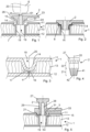
- the indentation may be rotationally symmetrical about an axis 20.
- the sonotrode 6 is used to press the anchoring portion into the indentation while mechanical vibrations are coupled into the anchoring portion.
- the anchoring portion has an opening 25 open towards proximally so that a guiding protrusion 61 of the sonotrode 6 may engage.
- the opening 25 is an axially running through opening.
- the anchoring portion 21 thereby is tube-like.
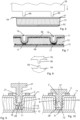
- Figure 7 shows the resulting first object, illustrated to have two indentations 19 being blind holes.
- the deformation process will lead to a re-orientation of the fibers, a local compaction of the interlining layer (dense zone 17), and possibly also to a matrix material (foam) enrichment and/or compaction yielding porosity for the anchoring process, in addition or as an alternative to a residual porosity between the fibers of the first building layer material.
- the shaping protrusion(s) 56 can be longer so that they extend to the first mold part 54, or the first mold part may have first mold part shaping protrusions 59 at corresponding positions, as shown in Figure 8 . In either case, after forming of the first and second building layers, a thin residual layer of building layer material may remain and may have to be removed in a separate step.
- Figure 10 illustrates the situation after anchoring, i.e. after the thermoplastic material has re-solidified.
- the flow portion 8 of the thermoplastic material comprises both, portions that have flown into structures of the sidewall, for example structures formed by exposed fibers, and portions that have interpenetrated the interlining.
- a punched-out piece 73 of the first building layer is displaced towards distally.
- the hollow space 28 may comprise debris of interlining material and/or first building layer material.
- a bottom 16 of the indentation may be removed prior to the anchoring process, for example by drilling.
- Figure 11 illustrates the possibility that the mechanical energy input in addition or as an alternative to comprising mechanical vibration may comprise (oscillatory or continuous) rotation of the second object 2 relative to the first object.
- the first object may be mounted in a fixed orientation, and the second object may be pressed against the first object by a rotation tool 81 rotating around the axis 20.
- the second object 2 may have a not rotationally symmetrical ("rotationally symmetrical" here implying rotational symmetry with respect to rotation about any angle, i.e.
- the coupling structure may optionally have a discrete symmetry, such as by being hexagonal or quadratic or star-shaped in cross section or slit-shaped) coupling structure, such as a coupling indentation, cooperating with a mating rotation tool coupling structure, such as a coupling protrusion 82.
- the indentation was assumed to be approximately round in cross section, i.e. rotationally symmetrical (with respect to rotation about any angle) about the axis 20. With the partial exception of the configuration of Fig. 11 that concerns the input of rotational energy, this need not be the case. Rather, as an alternative to being round ( Figure 12 ) in cross section, the indentation 19 may have any other shape, such as oblong ( Figure 13 ), oblong-curved ( Figure 14 ), etc. Figs. 12-14 all schematically show cross sections through a plane perpendicular to the axis.
- the anchoring portion of the second object may have an approximately adapted cross section, which however may deviate from the cross section of the indentation, for example by comprising a structure of the above-described kind with lamellae or similar.
- the outer cross section of the anchoring portion has an overall shape that differs from the cross section of the indentation, for example in that the anchoring portion is generally round (with the exception of the energy directing structures) whereas the indentation is for example oblong. Then, the resulting anchoring of the anchoring portion will be anisotropic, with a dominant anchoring at the side face portions where the indentation is narrower. This may be used for intentional anisotropies in the bending strength/flexibility, or also for some tolerance compensation.
- Figure 15 illustrates the principle that it is possible to make another object than a sandwich board by the primary shaping process.
- the first object 1 may for example comprise a structure of soaked fibers placed in a mould 55 having a salient feature that forms the indentation.
- Figure 16 shows the set-up for anchoring, including a second object 2 and a sonotrode.
- Another feature illustrated in Fig. 16 which is independent on the nature of the first object 1, is that the anchoring portion shaped to be inserted into the indentation and the indentation are adapted to each other for a press-fit, in that the anchoring portion is slightly oversized compared to the dimensions of the indentation (see the dashed lines).
- the anchoring method may especially comprise inserting the second object into the indentation so that a press-fit results (i.e. the second object is provisionally fixed to the first object) prior to the mechanical vibration energy input.
- the first outer building layer of the lightweight building element that forms the surface both, of the sidewall and of the proximally facing surface portion around the mouth of the indentation.
- the embodiment of Figs. 15 and 16 there is a smooth, continuous transition between the proximally facing surface portion 18 around the mouth and the sidewall 14. Also, both have a same texture.
- Object 1 as shown in all figures, but especially as shown in Fig. 16 may be a homogeneous body, such as a block of foam with an indentation. As can be seen in Fig. 16 , the surface portion 18 and sidewall 14 have the same texture.
- Figures 17-19 yet show different second objects 2.
- the embodiment of Fig. 17 has axially running ridges between which grooves of approximately triangular cross sections are established, wherein the grooves are, given the conical shape of the second object 2, deepen towards proximally.
- the grooves are not triangular but rectangular in cross section.
- the overall second object is not conical but cylindrical, and the axial length of the grooves/ridges may be chosen differently, with an example being shown in Fig. 4 .
- Fig. 19 shows an example with ridges that do not run into axial directions but circumferentially.
- the second object's anchoring portion in embodiments may have a conical shape up to approx. 30 degrees cone angle or be cylindrical.
- the external wall of the anchoring portion may contain features that act as energy directors, particularly vertical ridges or groove (with respect to the proximodistal direction) that are parallel to each other.
- the maximum number of grooves on the perimeter is a function of the insert portion's diameter, cone angle and the groove geometry.
- the grooves can have a triangular cross-section with an angle at the bottom of the groove ranging from 10 to 90 degrees or more, or a rectangular cross-section with or without rounded edges at the bottom of the grooves. Some other groove shapes could be imagined.
- the number of grooves can be chosen so that they don't overlap, as to retain the conical or cylindrical body (outer profile) between the grooves.
- the cross-section of the grooves changes along the height of the pin (insertion direction) when the anchoring portion is conical, being deeper at the top (bigger diameter of the cone) and shallower at the bottom of the cone.
Landscapes
- Engineering & Computer Science (AREA)
- Mechanical Engineering (AREA)
- Chemical & Material Sciences (AREA)
- Composite Materials (AREA)
- Lining Or Joining Of Plastics Or The Like (AREA)
Claims (15)
- Procédé de fabrication d'un ensemble, comprenant les étapes consistant à :- fournir un premier objet (1),o dans lequel le premier objet (1) a une partie de surface orientée de façon proximale (18),o dans lequel le premier objet (1) a une indentation (19) ayant une embouchure dans la surface orientée de façon proximale (18), l'indentation (19) étant fabriquée par pré-façonnage, l'indentation (19) ayant une paroi latérale (14) ;- fournir un second objet (2) qui a une partie de surface externe latérale (24),- dans lequel la partie de surface externe latérale (24) comprend un matériau thermoplastique ;- mettre le second objet (2) en contact avec le premier objet (1) de sorte que la partie de surface externe latérale (24) est en contact physique avec la paroi latérale (14) ;- accoupler l'énergie mécanique dans au moins l'un parmi les premiers et seconds objets (1 ; 2) de manière à provoquer une absorption d'énergie due au frottement entre la partie de surface externe latérale (24) et la paroi latérale (14), jusqu'à ce qu'une partie d'écoulement de la matière thermoplastique se liquéfie ; et- laisser la partie d'écoulement se resolidifier, moyennant quoi la partie d'écoulement fixe le second objet (2) au premier objet (1), dans lequel la partie d'écoulement interpénétre des structures du premier objet (1), en particulier la paroi latérale, de sorte qu'après la resolidification, il en résulte un ajustement positif.
- Procédé selon la revendication 1, dans lequel la paroi latérale (14) a une même texture que la surface orientée de façon proximale (18) dans une région autour de l'embouchure, dans lequel, de préférence, l'indentation (19) s'étend à partir de la partie de surface orientée de façon proximale (18) de manière lisse sans former un bord tranchant, dans lequel, de préférence, l'étape consistant à fournir le premier objet (1) comprend la fabrication du premier objet (1) par un processus de façonnage primaire, dans lequel l'indentation (19) est façonnée par le processus de façonnage primaire, dans lequel, de préférence, l'indentation (19) est formée pendant la fabrication du premier objet, dans lequel, de préférence, le processus de façonnage primaire est un processus de moulage, dans lequel, de préférence, l'indentation (19) et au moins une partie supplémentaire du premier objet (1), de préférence le premier objet complet, sont façonnées dans un même moule.
- Procédé selon l'une quelconque des revendications 1 à 2, dans lequel le processus de façonnage primaire est un processus en une étape.
- Procédé selon l'une quelconque des revendications 1 à 3, dans lequel le premier objet (1) comprend un matériau polymère, et dans lequel le matériau polymère est amené à durcir pendant le processus de façonnage primaire.
- Procédé selon l'une quelconque des revendications précédentes, dans lequel le second objet (2) a une partie d'ancrage ayant un contour externe adapté à l'indentation (19), dans lequel, de préférence, un diamètre externe de la partie d'ancrage (21) est adapté à l'indentation pour produire un ajustement serré, dans lequel, de préférence, une dimension de la partie d'ancrage (21) est supérieure à une dimension correspondante de l'indentation (19) d'entre 2% et 20 %, dans lequel, de préférence, l'indentation (19) forme une ouverture borgne dans le premier objet (1), l'ouverture borgne ayant un fond ayant la même texture que la surface orientée de façon proximale (18) dans une région autour de l'embouchure ou dans lequel l'indentation (19) forme une ouverture traversante et dans lequel la paroi latérale (14) s'étend de manière contiguë à partir de la surface orientée de façon proximale (18) du premier objet (1) avec une texture inchangée.
- Procédé selon l'une quelconque des revendications précédentes, dans lequel pendant l'accouplement de l'énergie mécanique dans le second objet (2), des structures interpénétrées par le matériau thermoplastique du second objet (2) sont générées dans le premier objet, dans lequel, de préférence, le premier objet (1) comprend une mousse, dans lequel, de préférence, le premier objet (1) est un élément de construction léger ayant une première couche de construction externe (11) et une couche intermédiaire (13), dans lequel la première couche de construction externe (11) est plus mince et plus dense que la couche intermédiaire (13), dans lequel la première couche de construction externe est façonnée pour constituer la paroi latérale (14) de l'indentation (19), dans lequel, de préférence, le premier objet (1) est une tablette de panneau arrière ou un panneau pour un moteur de voiture.
- Procédé de fabrication d'un ensemble d'éléments de construction légers, comprenant les étapes consistant à :- fournir un premier objet (1), le premier objet étant un élément de construction léger qui a une première couche de construction externe (11) et une couche intermédiaire (13),o dans lequel la première couche de construction externe (11) comprend un matériau de couche de construction renforcé par des fibres et est plus mince et plus dense que la couche intermédiaire (13),o et dans lequel le premier objet (1) a une indentation (19) formée par la première couche de construction externe (11), l'indentation (19) ayant une paroi latérale (14) du matériau de couche de construction ;- fournir un second objet (2) qui a une partie de surface externe latérale (24) d'un matériau thermoplastique ;- mettre le second objet (2) en contact avec le premier objet (1) de sorte que la partie de surface externe latérale (24) est en contact physique avec la paroi latérale ;- accoupler une énergie mécanique dans le second objet (2) de manière à provoquer une absorption d'énergie due au frottement entre la partie de surface externe latérale (24) et la paroi latérale (14), jusqu'à ce qu'une partie d'écoulement de matière thermoplastique se liquéfie et s'écoule par rapport à la paroi latérale (14) ; et- laisser la partie d'écoulement se resolidifier, moyennant quoi la partie d'écoulement fixe le second objet (2) au premier objet (1).
- Procédé selon la revendication 7, dans lequel l'indentation (19) a une embouchure dans un premier plan de couche de construction externe, dans lequel la première construction externe (11) a une partie plane autour de l'indentation (19), dans lequel la partie de paroi latérale (14) rencontre la partie plane au niveau de l'embouchure de l'indentation (19) et est contiguë à la partie plane, dans lequel, de préférence, l'indentation (19) forme une ouverture borgne dans le premier objet (1) et a un fond (16) du matériau de couche de construction, dans lequel, de préférence, l'indentation (19) forme une ouverture traversante dans le premier objet (1), dans lequel, de préférence, le premier objet (1) a, en plus de la première couche de construction externe (11), une seconde couche de construction externe (12), les première et seconde couches de construction prenant en sandwich la couche intermédiaire (13), dans lequel, de préférence, l'indentation (19) forme une ouverture traversante et dans lequel la paroi latérale (14) s'étend de manière contiguë depuis la première couche de construction (11) le long de l'ouverture jusqu'à la seconde couche de construction (12), dans lequel, de préférence, le matériau de couche de construction recouvre entièrement l'indentation (19), moyennant quoi une surface, en particulier une surface entière, du premier objet (1) à l'intérieur et autour de l'indentation (19) est formée par le matériau de couche de construction.
- Procédé selon la revendication 8, dans lequel, pendant l'étape consistant à accoupler l'énergie mécanique dans le second objet (2), le matériau de couche de construction reste contigu, moyennant quoi la couche intermédiaire (13) reste protégée du second objet (2) jusqu'à l'étape consistant à laisser la partie d'écoulement se resolidifier.
- Procédé selon la revendication 8, provoquant en outre la perturbation du matériau de couche de construction recouvrant l'indentation (19) par une action de perçage ou de poinçonnage du second objet (2), et dans lequel la partie d'écoulement comprend une partie amenée à s'écouler dans les structures de la couche intermédiaire (13).
- Procédé selon l'une quelconque des revendications 7 à 10, dans lequel l'étape consistant à fournir le premier objet (1) comprend la fabrication du premier objet (1) par un processus de façonnage primaire, dans lequel l'indentation (19) est façonnée par le processus de façonnage primaire, dans lequel le matériau de couche de construction comprend un matériau polymère et dans lequel le matériau polymère du matériau de couche de construction est amené à durcir pendant le processus de façonnage primaire, dans lequel, de préférence, la couche intermédiaire (13) comprend une structure de cellule, telle qu'une structure en nid d'abeille, et/ou une structure en mousse, dans lequel, de préférence, l'énergie mécanique comprend l'énergie de vibration mécanique, et dans lequel l'accouplement de l'énergie mécanique dans le second objet (2) comprend le pressage du second objet (2) contre le premier objet (1) par une sonotrode vibrante, dans lequel, de préférence, l'énergie mécanique comprend une énergie de rotation mécanique, et dans lequel l'accouplement de l'énergie mécanique dans le second objet (2) comprend le pressage du second objet (2) contre le premier objet (1) par un outil (81) soumis à une rotation, dans lequel, de préférence, la partie de surface externe latérale (24) a une structure d'indentations et de crêtes, dans lequel les crêtes forment des lamelles s'étendant dans l'axe.
- Procédé selon l'une quelconque des revendications précédentes, dans lequel le second objet (2) comprend une partie d'ancrage (21) qui forme la partie de surface externe latérale (24), dans lequel, pendant l'étape consistant à mettre en contact le second objet (2) avec le premier objet (1), la partie d'ancrage (21) est amenée à être insérée dans l'indentation (19), et dans lequel la partie de surface externe latérale (24) est au moins en partie cylindrique et/ou conique, dans lequel, de préférence, la partie d'ancrage (21) forme un espace creux, moyennant quoi au moins une partie distale du second objet (2) est essentiellement en forme de tube, dans lequel, de préférence, la partie d'ancrage (21) est en gradins, dans lequel, de préférence, le second objet (2) a une partie d'ancrage (21) et une partie fonctionnelle (23) d'une seule pièce avec la partie d'ancrage (21), dans lequel la partie fonctionnelle (23) n'est pas symétrique en rotation par rapport à une rotation d'un angle quelconque autour d'un axe de l'indentation (19), de préférence comprenant en outre l'étape consistant à fournir un élément fonctionnel (3), dans lequel l'élément fonctionnel (3) a une ouverture traversante d'élément fonctionnel (31), et dans lequel pendant l'étape consistant à mettre le second objet (2) en contact avec le premier objet (1), une partie du second objet (2) est amenée à s'étendre à travers l'ouverture traversante d'élément fonctionnel (31), dans lequel, de préférence, l'ouverture traversante d'élément fonctionnel (31) comprend un gradin et/ou un cône, moyennant quoi une largeur de l'ouverture traversante d'élément fonctionnel (31) se rétrécit vers la partie distale, et dans lequel, pendant l'étape consistant à accoupler l'énergie mécanique dans le second objet, le second objet (2) est amené à être pressé contre le gradin et/ou le cône.
- Procédé selon la revendication 12, dans lequel le second objet (2) a une partie tête (27) et dans lequel, pendant l'étape consistant à accoupler l'énergie mécanique dans le second objet (2), la partie tête (27) est pressée contre une partie de surface orientée de façon proximale de l'élément fonctionnel (3), dans lequel, de préférence, l'élément fonctionnel (3) est au moins partiellement thermoplastique et est amené à être soudé au second objet pendant l'étape consistant à accoupler l'énergie mécanique dans le second objet (2).
- Ensemble fabriqué par le procédé selon l'une quelconque des revendications précédentes, l'ensemble comprenant le premier objet (1) et comprend en outre le second objet (2) fixé au premier objet (1).
- Ensemble selon la revendication 14, comprenant un élément de construction léger en tant que premier objet (1), l'élément de construction léger comprenant une première couche de construction externe (11) formant une indentation (19) et une couche intermédiaire (13), dans lequel, de préférence, l'élément de construction léger a en outre une seconde couche de construction externe (12), les première et seconde couches de construction externe prenant en sandwich la couche intermédiaire (13), dans lequel le matériau de la première couche de construction externe (11) s'étend de manière continue le long de l'indentation (19) jusqu'à la seconde couche de construction (12), moyennant quoi l'indentation (19) forme une ouverture traversante, et moyennant quoi la couche intermédiaire (13) est au moins partiellement protégée d'un extérieur dans une région de l'indentation (19).
Applications Claiming Priority (2)
| Application Number | Priority Date | Filing Date | Title |
|---|---|---|---|
| CH15172019 | 2019-11-29 | ||
| PCT/EP2020/083773 WO2021105454A1 (fr) | 2019-11-29 | 2020-11-27 | Fixation solide d'un second objet à un premier objet |
Publications (3)
| Publication Number | Publication Date |
|---|---|
| EP4065348A1 EP4065348A1 (fr) | 2022-10-05 |
| EP4065348C0 EP4065348C0 (fr) | 2025-04-16 |
| EP4065348B1 true EP4065348B1 (fr) | 2025-04-16 |
Family
ID=69500519
Family Applications (1)
| Application Number | Title | Priority Date | Filing Date |
|---|---|---|---|
| EP20811659.0A Active EP4065348B1 (fr) | 2019-11-29 | 2020-11-27 | Fixation solide d'un second objet à un premier objet |
Country Status (4)
| Country | Link |
|---|---|
| US (1) | US12384117B2 (fr) |
| EP (1) | EP4065348B1 (fr) |
| CN (1) | CN114761209B (fr) |
| WO (1) | WO2021105454A1 (fr) |
Families Citing this family (3)
| Publication number | Priority date | Publication date | Assignee | Title |
|---|---|---|---|---|
| US20240217183A1 (en) * | 2023-01-03 | 2024-07-04 | Rohr, Inc. | Thermoplastic composite component with vibration welded non-parallel surfaces and method for producing the same |
| JPWO2024180868A1 (fr) * | 2023-02-28 | 2024-09-06 | ||
| EP4600505A1 (fr) * | 2024-02-09 | 2025-08-13 | Schmitz Cargobull AG | Procédé de fabrication d'un panneau doté d'une couche centrale et panneau doté d'une couche centrale et véhicule utilitaire doté d'un panneau |
Citations (1)
| Publication number | Priority date | Publication date | Assignee | Title |
|---|---|---|---|---|
| US20170334147A1 (en) * | 2014-11-04 | 2017-11-23 | Woodwelding Ag | Bonding objects together |
Family Cites Families (9)
| Publication number | Priority date | Publication date | Assignee | Title |
|---|---|---|---|---|
| CH694058A5 (de) * | 1999-06-18 | 2004-06-30 | Woodwelding Ag | Stoffschlüssiges Verbinden. |
| US8528299B2 (en) * | 2008-12-23 | 2013-09-10 | Woodwelding Ag | Method of anchoring a connector, and connector |
| EP3307519B1 (fr) * | 2015-06-11 | 2020-11-25 | Woodwelding AG | Ancrage dans un élément de construction léger |
| EP3307521B1 (fr) * | 2015-06-11 | 2020-05-13 | Woodwelding AG | Fixation d'un second objet à un premier objet |
| GB201516237D0 (en) * | 2015-09-14 | 2015-10-28 | Ellis Patents Holdings Ltd | A clamp |
| EP3433500B1 (fr) * | 2016-03-21 | 2023-12-13 | Multimaterial-Welding AG | Fixation d'un deuxième objet à un premier objet |
| CN109789640B (zh) * | 2016-07-21 | 2021-12-28 | 多种材料焊接股份公司 | 将第二物体锚固至第一物体 |
| US20210146635A1 (en) * | 2017-09-27 | 2021-05-20 | Woodwelding Ag | Securing a second object to a first object |
| JP6920981B2 (ja) * | 2017-12-25 | 2021-08-18 | 株式会社クラレ | シート成形体の製造方法 |
-
2020
- 2020-11-27 US US17/780,179 patent/US12384117B2/en active Active
- 2020-11-27 EP EP20811659.0A patent/EP4065348B1/fr active Active
- 2020-11-27 CN CN202080082771.3A patent/CN114761209B/zh active Active
- 2020-11-27 WO PCT/EP2020/083773 patent/WO2021105454A1/fr not_active Ceased
Patent Citations (1)
| Publication number | Priority date | Publication date | Assignee | Title |
|---|---|---|---|---|
| US20170334147A1 (en) * | 2014-11-04 | 2017-11-23 | Woodwelding Ag | Bonding objects together |
Also Published As
| Publication number | Publication date |
|---|---|
| EP4065348C0 (fr) | 2025-04-16 |
| US20220410496A1 (en) | 2022-12-29 |
| WO2021105454A1 (fr) | 2021-06-03 |
| CN114761209B (zh) | 2024-11-12 |
| CN114761209A (zh) | 2022-07-15 |
| EP4065348A1 (fr) | 2022-10-05 |
| US12384117B2 (en) | 2025-08-12 |
Similar Documents
| Publication | Publication Date | Title |
|---|---|---|
| US11345096B2 (en) | Anchoring in a lightweight building element | |
| EP3307521B1 (fr) | Fixation d'un second objet à un premier objet | |
| EP4065348B1 (fr) | Fixation solide d'un second objet à un premier objet | |
| CN107107476B (zh) | 将物体结合在一起 | |
| JP7134996B2 (ja) | 物体の接合方法および被接合部材に接合される物体 | |
| EP3487686B1 (fr) | Fixation d'un second objet à un premier objet | |
| CN115157686B (zh) | 将第二物体锚固至第一物体 | |
| US20210146635A1 (en) | Securing a second object to a first object |
Legal Events
| Date | Code | Title | Description |
|---|---|---|---|
| STAA | Information on the status of an ep patent application or granted ep patent |
Free format text: STATUS: UNKNOWN |
|
| STAA | Information on the status of an ep patent application or granted ep patent |
Free format text: STATUS: THE INTERNATIONAL PUBLICATION HAS BEEN MADE |
|
| PUAI | Public reference made under article 153(3) epc to a published international application that has entered the european phase |
Free format text: ORIGINAL CODE: 0009012 |
|
| STAA | Information on the status of an ep patent application or granted ep patent |
Free format text: STATUS: REQUEST FOR EXAMINATION WAS MADE |
|
| 17P | Request for examination filed |
Effective date: 20220628 |
|
| AK | Designated contracting states |
Kind code of ref document: A1 Designated state(s): AL AT BE BG CH CY CZ DE DK EE ES FI FR GB GR HR HU IE IS IT LI LT LU LV MC MK MT NL NO PL PT RO RS SE SI SK SM TR |
|
| DAV | Request for validation of the european patent (deleted) | ||
| DAX | Request for extension of the european patent (deleted) | ||
| STAA | Information on the status of an ep patent application or granted ep patent |
Free format text: STATUS: EXAMINATION IS IN PROGRESS |
|
| 17Q | First examination report despatched |
Effective date: 20240613 |
|
| GRAP | Despatch of communication of intention to grant a patent |
Free format text: ORIGINAL CODE: EPIDOSNIGR1 |
|
| STAA | Information on the status of an ep patent application or granted ep patent |
Free format text: STATUS: GRANT OF PATENT IS INTENDED |
|
| INTG | Intention to grant announced |
Effective date: 20250122 |
|
| GRAS | Grant fee paid |
Free format text: ORIGINAL CODE: EPIDOSNIGR3 |
|
| GRAA | (expected) grant |
Free format text: ORIGINAL CODE: 0009210 |
|
| STAA | Information on the status of an ep patent application or granted ep patent |
Free format text: STATUS: THE PATENT HAS BEEN GRANTED |
|
| AK | Designated contracting states |
Kind code of ref document: B1 Designated state(s): AL AT BE BG CH CY CZ DE DK EE ES FI FR GB GR HR HU IE IS IT LI LT LU LV MC MK MT NL NO PL PT RO RS SE SI SK SM TR |
|
| REG | Reference to a national code |
Ref country code: GB Ref legal event code: FG4D |
|
| REG | Reference to a national code |
Ref country code: CH Ref legal event code: EP |
|
| REG | Reference to a national code |
Ref country code: IE Ref legal event code: FG4D |
|
| REG | Reference to a national code |
Ref country code: DE Ref legal event code: R096 Ref document number: 602020049633 Country of ref document: DE |
|
| U01 | Request for unitary effect filed |
Effective date: 20250514 |
|
| U07 | Unitary effect registered |
Designated state(s): AT BE BG DE DK EE FI FR IT LT LU LV MT NL PT RO SE SI Effective date: 20250521 |
|
| PG25 | Lapsed in a contracting state [announced via postgrant information from national office to epo] |
Ref country code: ES Free format text: LAPSE BECAUSE OF FAILURE TO SUBMIT A TRANSLATION OF THE DESCRIPTION OR TO PAY THE FEE WITHIN THE PRESCRIBED TIME-LIMIT Effective date: 20250416 |
|
| PG25 | Lapsed in a contracting state [announced via postgrant information from national office to epo] |
Ref country code: NO Free format text: LAPSE BECAUSE OF FAILURE TO SUBMIT A TRANSLATION OF THE DESCRIPTION OR TO PAY THE FEE WITHIN THE PRESCRIBED TIME-LIMIT Effective date: 20250716 Ref country code: GR Free format text: LAPSE BECAUSE OF FAILURE TO SUBMIT A TRANSLATION OF THE DESCRIPTION OR TO PAY THE FEE WITHIN THE PRESCRIBED TIME-LIMIT Effective date: 20250717 |
|
| PG25 | Lapsed in a contracting state [announced via postgrant information from national office to epo] |
Ref country code: PL Free format text: LAPSE BECAUSE OF FAILURE TO SUBMIT A TRANSLATION OF THE DESCRIPTION OR TO PAY THE FEE WITHIN THE PRESCRIBED TIME-LIMIT Effective date: 20250416 |
|
| PG25 | Lapsed in a contracting state [announced via postgrant information from national office to epo] |
Ref country code: HR Free format text: LAPSE BECAUSE OF FAILURE TO SUBMIT A TRANSLATION OF THE DESCRIPTION OR TO PAY THE FEE WITHIN THE PRESCRIBED TIME-LIMIT Effective date: 20250416 |
|
| PG25 | Lapsed in a contracting state [announced via postgrant information from national office to epo] |
Ref country code: RS Free format text: LAPSE BECAUSE OF FAILURE TO SUBMIT A TRANSLATION OF THE DESCRIPTION OR TO PAY THE FEE WITHIN THE PRESCRIBED TIME-LIMIT Effective date: 20250716 |
|
| PG25 | Lapsed in a contracting state [announced via postgrant information from national office to epo] |
Ref country code: IS Free format text: LAPSE BECAUSE OF FAILURE TO SUBMIT A TRANSLATION OF THE DESCRIPTION OR TO PAY THE FEE WITHIN THE PRESCRIBED TIME-LIMIT Effective date: 20250816 |
|
| U20 | Renewal fee for the european patent with unitary effect paid |
Year of fee payment: 6 Effective date: 20251127 |
|
| PG25 | Lapsed in a contracting state [announced via postgrant information from national office to epo] |
Ref country code: SM Free format text: LAPSE BECAUSE OF FAILURE TO SUBMIT A TRANSLATION OF THE DESCRIPTION OR TO PAY THE FEE WITHIN THE PRESCRIBED TIME-LIMIT Effective date: 20250416 |
|
| PG25 | Lapsed in a contracting state [announced via postgrant information from national office to epo] |
Ref country code: CZ Free format text: LAPSE BECAUSE OF FAILURE TO SUBMIT A TRANSLATION OF THE DESCRIPTION OR TO PAY THE FEE WITHIN THE PRESCRIBED TIME-LIMIT Effective date: 20250416 |
|
| PG25 | Lapsed in a contracting state [announced via postgrant information from national office to epo] |
Ref country code: SK Free format text: LAPSE BECAUSE OF FAILURE TO SUBMIT A TRANSLATION OF THE DESCRIPTION OR TO PAY THE FEE WITHIN THE PRESCRIBED TIME-LIMIT Effective date: 20250416 |
|
| PLBE | No opposition filed within time limit |
Free format text: ORIGINAL CODE: 0009261 |
|
| STAA | Information on the status of an ep patent application or granted ep patent |
Free format text: STATUS: NO OPPOSITION FILED WITHIN TIME LIMIT |
|
| REG | Reference to a national code |
Ref country code: CH Ref legal event code: L10 Free format text: ST27 STATUS EVENT CODE: U-0-0-L10-L00 (AS PROVIDED BY THE NATIONAL OFFICE) Effective date: 20260225 |
|
| 26N | No opposition filed |
Effective date: 20260119 |