EP4065387B1 - Fahrzeugluftreifen - Google Patents
Fahrzeugluftreifen Download PDFInfo
- Publication number
- EP4065387B1 EP4065387B1 EP20792371.5A EP20792371A EP4065387B1 EP 4065387 B1 EP4065387 B1 EP 4065387B1 EP 20792371 A EP20792371 A EP 20792371A EP 4065387 B1 EP4065387 B1 EP 4065387B1
- Authority
- EP
- European Patent Office
- Prior art keywords
- profile
- sipes
- pneumatic vehicle
- cavities
- incisions
- Prior art date
- Legal status (The legal status is an assumption and is not a legal conclusion. Google has not performed a legal analysis and makes no representation as to the accuracy of the status listed.)
- Active
Links
Images

Classifications
-
- B—PERFORMING OPERATIONS; TRANSPORTING
- B60—VEHICLES IN GENERAL
- B60C—VEHICLE TYRES; TYRE INFLATION; TYRE CHANGING; CONNECTING VALVES TO INFLATABLE ELASTIC BODIES IN GENERAL; DEVICES OR ARRANGEMENTS RELATED TO TYRES
- B60C11/00—Tyre tread bands; Tread patterns; Anti-skid inserts
- B60C11/03—Tread patterns
- B60C11/12—Tread patterns characterised by the use of narrow slits or incisions, e.g. sipes
- B60C11/1272—Width of the sipe
- B60C11/1281—Width of the sipe different within the same sipe, i.e. enlarged width portion at sipe bottom or along its length
-
- B—PERFORMING OPERATIONS; TRANSPORTING
- B60—VEHICLES IN GENERAL
- B60C—VEHICLE TYRES; TYRE INFLATION; TYRE CHANGING; CONNECTING VALVES TO INFLATABLE ELASTIC BODIES IN GENERAL; DEVICES OR ARRANGEMENTS RELATED TO TYRES
- B60C11/00—Tyre tread bands; Tread patterns; Anti-skid inserts
- B60C11/03—Tread patterns
- B60C11/032—Patterns comprising isolated recesses
-
- B—PERFORMING OPERATIONS; TRANSPORTING
- B60—VEHICLES IN GENERAL
- B60C—VEHICLE TYRES; TYRE INFLATION; TYRE CHANGING; CONNECTING VALVES TO INFLATABLE ELASTIC BODIES IN GENERAL; DEVICES OR ARRANGEMENTS RELATED TO TYRES
- B60C11/00—Tyre tread bands; Tread patterns; Anti-skid inserts
- B60C11/03—Tread patterns
- B60C11/12—Tread patterns characterised by the use of narrow slits or incisions, e.g. sipes
- B60C11/1204—Tread patterns characterised by the use of narrow slits or incisions, e.g. sipes with special shape of the sipe
- B60C11/1218—Three-dimensional shape with regard to depth and extending direction
-
- B—PERFORMING OPERATIONS; TRANSPORTING
- B60—VEHICLES IN GENERAL
- B60C—VEHICLE TYRES; TYRE INFLATION; TYRE CHANGING; CONNECTING VALVES TO INFLATABLE ELASTIC BODIES IN GENERAL; DEVICES OR ARRANGEMENTS RELATED TO TYRES
- B60C11/00—Tyre tread bands; Tread patterns; Anti-skid inserts
- B60C11/03—Tread patterns
- B60C11/12—Tread patterns characterised by the use of narrow slits or incisions, e.g. sipes
- B60C11/1236—Tread patterns characterised by the use of narrow slits or incisions, e.g. sipes with special arrangements in the tread pattern
- B60C2011/1245—Tread patterns characterised by the use of narrow slits or incisions, e.g. sipes with special arrangements in the tread pattern being arranged in crossing relation, e.g. sipe mesh
-
- B—PERFORMING OPERATIONS; TRANSPORTING
- B60—VEHICLES IN GENERAL
- B60C—VEHICLE TYRES; TYRE INFLATION; TYRE CHANGING; CONNECTING VALVES TO INFLATABLE ELASTIC BODIES IN GENERAL; DEVICES OR ARRANGEMENTS RELATED TO TYRES
- B60C11/00—Tyre tread bands; Tread patterns; Anti-skid inserts
- B60C11/03—Tread patterns
- B60C11/12—Tread patterns characterised by the use of narrow slits or incisions, e.g. sipes
- B60C11/1236—Tread patterns characterised by the use of narrow slits or incisions, e.g. sipes with special arrangements in the tread pattern
- B60C2011/1254—Tread patterns characterised by the use of narrow slits or incisions, e.g. sipes with special arrangements in the tread pattern with closed sipe, i.e. not extending to a groove
Definitions
- the invention is a pneumatic vehicle tire with a profiled tread with profile elements, such as profile blocks or profile ribs, in which incisions with a width of 0.4 mm to 1.0 mm each form a group of incisions and merge into one another at an intersection, with the incisions in particular Connect cylindrical or tube section-shaped cavities at a constant depth of 50% to 80% of the tread depth of the tire.
- profile elements such as profile blocks or profile ribs
- Such a pneumatic vehicle tire is from the DE 10 2013 111 197 A1 known.
- This tire is provided with a tread which has at least one profile rib in which a large number of groups of incisions made of cross-slot-shaped incisions are arranged in a row in the circumferential direction. Two of these incisions run in alignment with one another in the circumferential direction and merge into a cavity extending in the circumferential direction inside the profile rib.
- Helmholtz resonators are formed in the profile rib.
- the shaped elements, which form such incisions with cavities in a vulcanization mold during the vulcanization of the pneumatic vehicle tire can be easily formed from the rubber material of the tread due to their cross shape after vulcanization.
- the sound absorption is limited in terms of frequencies.
- incisions are provided in a profile rib, which form a group of incisions, open together into a tubular channel running in the radial direction and diverge in a radial manner starting from the channel. Furthermore, the incisions open out in the radial direction their entire extension into a further tubular channel running at a constant depth, which also runs to the tubular channel running in the radial direction.
- the tire should have good wet and ice performance.
- a pneumatic vehicle tire is known with a tread with profile elements, in which at least three incisions form a group of incisions, the incisions ending within the respective profile element, joining one another at an intersection and twisting spirally over their depth profile in the radial direction.
- the cuts are intended, among other things, to be beneficial for braking properties on ice.
- a pneumatic vehicle tire with a tread profile elements in which at least three incisions form a group of incisions, the incisions ending within the respective profile element, opening into one another at an intersection and each being widened via a local channel running in the radial direction.
- the tire should have good braking properties on ice.
- the invention is based on the object of designing the Helmholtz resonators formed by incisions and cavities in a pneumatic vehicle tire of the type mentioned in such a way that a broader band of disturbing frequencies can be absorbed, with damage-free removal of the mold elements forming the incisions and cavities in the rubber material should be guaranteed.
- the Helmholtz resonators formed in this way should not affect the stability of the profile elements.
- the group of incisions consists of three incisions, which radiate apart from their intersection point and to which a cavity is connected in the interior of the profile element, with all cavities opening into one another at the intersection point, whereby either all of the incisions in the incision group run and end within the profile element or wherein at least one incision, at most two incisions, of an incision group runs or runs up to a groove delimiting the profile element, the cavity belonging to this incision either opening into the groove or ending within the profile element.
- three incisions together with cavities therefore form a Helmholtz resonator with a cavity of three chambers which are in communication with one another.
- the larger cavity formed in this way allows a significantly better adjustment of the disruptive frequencies to be absorbed compared to the known design.
- the radial arrangement of the cuts has little or no effect on the stability of the profile elements.
- the mold elements that form the incisions and cavities during the vulcanization of the tire can be easily removed due to their radial configuration when the tire is formed from the vulcanization mold by opening the incisions.
- the incisions in a group of incisions can be of the same length or of different lengths.
- the length of the cavities can, but does not have to, be adapted to the length of the incisions.
- the possible configurations in this regard advantageously allow good adaptation to the frequencies to be absorbed.
- Cavities that open into a circumferential or transverse groove like an incision can also contribute to the drainage of the tread.
- a generally round depression is formed at the intersection of the incisions on the outer surface of the profile element, which has a greatest depth of 1.5 mm to 2.5 mm.
- the depression ensures even wear of the tread in the area of intersections, as unfavorable acute-angled corners are avoided.
- the depressions are particularly circular in plan view and have a diameter of 2.0 mm to 4.0 mm. Cylindrical or tube section-shaped cavities with a largest diameter, which is 1.5 to 2.5 times the width of the incisions, are also particularly effective.
- the incisions at their end regions facing away from the crossing point are delimited in the radial direction by an end flank which runs at an angle of 25° to 35° to the radial direction, such that that the extent of each incision, starting from the outer surface of the profile element, becomes increasingly smaller over its course in the radial direction.
- the cuts themselves also have an effect on the traction and braking performance of the tire.
- the incisions and their cavities run straight or curved in plan view, in particular flat V-shaped.
- the incisions of a group of incisions at the intersection enclose an angle with one another which is 120° +/- 30°.
- cavities ending within the profile element have a length of 10.0 mm to 30.0 mm.
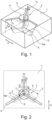
- Fig. 1 and Fig. 2 show views of a tread block 1 of a tread of a radial-type pneumatic vehicle tire, in particular for a passenger car.
- the tread block 1 shown only schematically and therefore in the shape of a cuboid, is part of a row of blocks (not shown) running in the circumferential direction of the tread, the tread blocks of which are separated from one another by transverse grooves. Rows of blocks that run in the middle area of the tread usually have circumferential grooves running in the circumferential direction on both sides, rows of blocks running on the shoulder side are only limited on the inside of the tread by a circumferential groove running in the circumferential direction. In Fig. 1 and Fig. 2 the circumferential direction of the tread is indicated by the double arrow U.
- an incision group 2 is formed from three incisions 3, which radiate from a common central area and end in the profile block 1 and therefore do not open into any groove.
- the center lines m ( Fig. 2 ) of the incisions 3 therefore each form an angle ⁇ , which in the example is 120° and can deviate from 120° by up to +/- 30°.
- the incisions 3 open into one another over their radial extent in the central area, which forms an intersection, with a generally round recess 4 being formed on the surface of the outer surface of the profile block 1 in the area of the intersection.
- the depression 4 is circular in plan view, otherwise it is in the shape of a spherical section and at most hemispherical.
- the diameter d 1 of the recess 4 on the outer surface of the profile block 1 is 2.0 mm to 4.0 mm, its greatest depth t 1 is 1.5 mm to 2.5 mm.
- the recess 4 can be elliptical or oval in plan view.
- the incisions 3 extend in the radial direction to a particularly constant depth tz, which is 50% to 90% of the intended tread depth - this is usually the depth of the wide circumferential grooves in the tire. In each case a narrow end flank 5 runs at the closed ends of the incisions 3.
- the end flanks 5 therefore connect the incision walls and extend to the radial direction at an acute angle ⁇ of 25° to 35°, in particular of the order of 30°, so that the extent of each Incision 3, parallel to the outer surface of the profile block 1, starting from the outer surface of the profile block 1 over its course in the radial direction becomes increasingly smaller.
- Each incision 3 opens into a cylindrical cavity 6, which extends over the length of the incision 3 at a depth t 2 and has a particularly constant diameter d 2 , which is 1.5 to 2.5 times the width b 1 of incision 3 is. After each incision 3 is provided with a cavity 6, all of the cavities 6 open into one another at the intersection within the profile block 1.
- the cavities 6 In extension of the end flanks 5, the cavities 6 have end surfaces 6a, which enclose the angle ⁇ with the radial direction analogous to the end flanks 5.
- the incisions 3 and the cavities 6 are matched to one another with regard to their longitudinal extent in such a way that the cavities 6 extend over a length l of 10.0 mm to 30.0 mm starting from the center of the intersection.
- the dimensions of the incisions 3 and the cavities 6 are coordinated with one another in such a way that the Helmholtz resonator, as a resonance absorber, specifically absorbs disruptive frequencies.
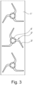
- Fig. 3 and Fig. 4 show a further embodiment of the invention, Fig. 3 based on a circumferential section of a profile rib 1 ', in which a large number of incision groups 2 ' are formed one after the other in the circumferential direction, Fig. 4 based on a top view of a section of the profile rib 1 'with a group of cuts 2'.
- the incision group 2' differs from that of the first embodiment in the course of the incisions 3' forming the incision group 2', which in plan view are not straight but run in a flat V-shaped arc starting from the central recess 4' and the crossing point.
- the incisions 3' are therefore composed, in plan view, of two incision sections 3'a, 3'b, with the incision sections 3'a, which adjoin the crossing point, extending to one another at the aforementioned angle ⁇ .
- the incision sections 3'a merge into the incision sections 3'b via curves, so that the two incision sections 3'a, 3'b enclose an angle ⁇ with one another, which is 90° to 170°, in particular 130° to 160°.
- Cavities 6' adjoin each incision 3' at depth t 2 in an analogous manner to the cavities 6 of the first embodiment and also run in an arc shape, due to the inclination of the end flanks 5' of the incisions 3' relative to the radial direction - angle ⁇ out Fig.
- the end faces 6'a of the cavities 6' extend in continuation of the end flanks 5'.
- the crossing point is designed like a hole through rounded transitions between the opening incisions 3'.
- the cavities 6' each have a length l' of 10.0 mm to 30.0 mm along the center lines m' - between the center of the recess 4' and its ends.
- the preferred arrangement of the incision groups 2, 2' within the profile blocks 1 of a profile block row or within a profile rib 1' is such that one of the incisions 3, 3' extends in the circumferential direction or essentially in the circumferential direction.
- Fig. 5 shows an embodiment variant in which one of the three incisions 3" of an incision group 2" extending from a common intersection with a recess 4" extends to the lateral edge of the profile rib 1".
- the incisions 3" are positioned analogously to the incisions 3' Fig. 4 in plan view from two incision sections 3"a, 3"b, the incision sections 3"a, which adjoin the crossing point, extending to one another at the mentioned angle ⁇ .
- the incision 3" which extends to the lateral edge of the profile rib 1" has a longer incision section 3"b than the two other incisions 3".
- the cavities 6" run in the same direction Fig. 4 , in which up to the side Incision 3" running on the edge of the profile rib 1", the cavity 6" can also open into the circumferential groove, not shown, which adjoins the profile rib 1" laterally.
Landscapes
- Engineering & Computer Science (AREA)
- Mechanical Engineering (AREA)
- Tires In General (AREA)
Description
- Die Erfindung einen Fahrzeugluftreifen mit einem profilierten Laufstreifen mit Profilelementen, wie Profilblöcken oder Profilrippen, in welchen Einschnitte mit einer Breite von 0,4 mm bis 1,0 mm jeweils eine Einschnittgruppe bilden und an einer Kreuzungsstelle ineinander einmünden, wobei an die Einschnitte in einer insbesondere konstanten Tiefe von 50% bis 80% der Profiltiefe des Reifens zylinderförmige oder rohrabschnittsförmige Hohlräume anschließen.
- Ein derartiger Fahrzeugluftreifen ist aus der
DE 10 2013 111 197 A1 bekannt. Dieser Reifen ist mit einem Laufstreifen versehen, welcher zumindest eine Profilrippe aufweist, in welcher in Umfangsrichtung aneinandergereiht eine Vielzahl von Einschnittgruppen aus kreuzschlitzförmig ausgebildeten Einschnitten vorgesehen ist. Zwei dieser Einschnitte verlaufen in Umfangsrichtung fluchtend zueinander und gehen im Inneren der Profilrippe jeweils in einen sich in Umfangsrichtung erstreckenden Hohlraum über. Auf diese Weise sind in der Profilrippe Helmholtz-Resonatoren ausgebildet. Die Formelemente, die während der Vulkanisation des Fahrzeugluftreifens in einer Vulkanisationsform derartige Einschnitte mit Hohlräumen ausbilden, lassen sich durch ihre Kreuzform nach der Vulkanisation aus dem Gummimaterial des Laufstreifens gut ausformen. Bei dieser bekannten Ausführung ist die Schallabsorption hinsichtlich der Frequenzen eingeschränkt. - Ferner ist aus der
EP 3 521 064 A1 ein Fahrzeugluftreifen mit einem Laufstreifen mit Profilrippen bekannt. Gemäß einem Ausführungsbeispiel sind in einer Profilrippe Einschnitte vorgesehen, welche eine Einschnittgruppe bilden, gemeinsam in einen in radialer Richtung verlaufenden rohrförmigen Kanal einmünden und ausgehend vom Kanal strahlenförmig auseinanderlaufen. Ferner münden die Einschnitte in radialer Richtung über ihre gesamte Erstreckung jeweils in einen in einer konstanten Tiefe verlaufenden weiteren rohrförmigen Kanal ein, welcher ebenfalls zum in den radialer Richtung verlaufenden rohrförmigen Kanal verläuft. Der Reifen soll eine gute Nässe- und Eisperformance aufweisen. - Aus der
EP 2 450 200 A1 ist ein Fahrzeugluftreifen mit einem Laufstreifen mit Profilelementen bekannt, in welchen zumindest jeweils drei Einschnitte eine Einschnittgruppe bilden, wobei die Einschnitte innerhalb des jeweiligen Profilelementes enden, an einer Kreuzungsstelle ineinander einmünden und sich über ihren in radialer Richtung vorliegenden Tiefenverlauf spiralförmig verdrehen. Die Einschnitte sollen unter anderem für die Bremseigenschaften auf Eis günstig sein. - Weiter ist aus der
EP 2 450 201 A1 ein Fahrzeugluftreifen mit einem Laufstreifen Profilelementen bekannt, in welchen zumindest jeweils drei Einschnitte eine Einschnittgruppe bilden, wobei die Einschnitte innerhalb des jeweiligen Profilelementes enden, an einer Kreuzungsstelle ineinander einmünden und jeweils über einen lokalen in radialer Richtung verlaufenden Kanal verbreitert sind. Der Reifen soll gute Bremseigenschaften auf Eis aufweisen. - Der Erfindung liegt die Aufgabe zugrunde, bei einem Fahrzeugluftreifen eingangs genannter Art die von Einschnitten und Hohlräumen gebildeten Helmholtz-Resonatoren derart auszubilden, dass ein breiteres Band an störenden Frequenzen absorbiert werden kann, wobei eine beschädigungsfreie Entformung der die Einschnitte und Hohlräume im Gummimaterial ausbildenden Formelemente weiterhin gewährleistet sein soll. Darüber hinaus sollen die derart gebildeten Helmholtz-Resonatoren die Stabilität der Profilelemente nicht beeinträchtigen.
- Gelöst wird die gestellte Aufgabe erfindungsgemäß dadurch, dass die Einschnittgruppe aus drei Einschnitten besteht, welche von ihrer Kreuzungsstelle ausgehend strahlenförmig auseinanderlaufen und an welche im Profilelementinneren jeweils ein Hohlraum anschließt, wobei sämtliche Hohlräume an der Kreuzungsstelle ineinander einmünden, wobei entweder sämtliche Einschnitte der Einschnittgruppe innerhalb des Profilelementes verlaufen und enden oder
wobei zumindest ein Einschnitt, höchstens zwei Einschnitte, einer Einschnittgruppe bis zu einer das Profilelement begrenzenden Rille verläuft bzw. verlaufen, wobei der zu diesem Einschnitt gehörende Hohlraum entweder in die Rille einmündet oder innerhalb des Profilelementes endet. - Gemäß der Erfindung bilden daher drei Einschnitte gemeinsam mit Hohlräumen einen Helmholtz-Resonator mit einer Kavität aus drei Kammern, die miteinander in Verbindung sind. Die derart gebildete größere Kavität erlaubt gegenüber der bekannten Ausführung eine wesentlich bessere Einstellung der zu absorbierenden, störenden Frequenzen. Darüber hinaus hat die strahlenförmige Anordnung der Einschnitte keine oder kaum Auswirkungen auf die Stabilität der Profilelemente. Die die Einschnitte und Hohlräume bei der Vulkanisation des Reifens ausformenden Formelemente lassen sich in Folge ihrer strahlenförmigen Ausgestaltung bei der Ausformung des Reifens aus der Vulkanisationsform unter Öffnen der Einschnitte leicht entfernen.
- Dabei können die Einschnitte einer Einschnittgruppe gleich lang oder auch unterschiedlich lang ausgeführt sein. Die Länge der Hohlräume kann, muss jedoch nicht an die Länge der Einschnitte entsprechend angepasst sein. Die diesbezüglich möglichen Ausgestaltungen erlauben vorteilhafterweise eine gute Anpassung an die zu absorbierenden Frequenzen.
- Hohlräume, die wie ein Einschnitt in eine Umfangs- oder Querrille einmünden, können zusätzlich einen Beitrag zur Entwässerung des Laufstreifens leisten.
- Bei einer weiteren bevorzugten Ausführung ist an der Kreuzungsstelle der Einschnitte an der Außenfläche des Profilelementes eine insgesamt runde Vertiefung ausgebildet, die eine größte Tiefe von 1,5 mm bis 2,5 mm aufweist. Die Vertiefung sorgt für einen gleichmäßigen Abrieb des Laufstreifens im Bereich der Kreuzungsstellen, da ungünstige spitzwinkelige Ecken vermieden sind. Dabei sind die Vertiefungen in Draufsicht insbesondere kreisförmig und weisen einen Durchmesser von 2,0 mm bis 4,0 mm auf. Besonders wirkungsvoll sind ferner zylinder- oder rohrabschnittförmige Hohlräume mit einem größten Durchmesser, welcher das 1,5- bis 2,5- Fache der Breite der Einschnitte beträgt.
- Für die Stabilität der Profilelemente mit zunehmendem Laufstreifenabrieb ist es ferner von Vorteil, wenn die Einschnitte an ihren von der Kreuzungsstelle abgewandten Endbereichen in radialer Richtung von einer Endflanke begrenzt sind, die zur radialen Richtung unter einem Winkel von 25° bis 35° verläuft, derart, dass die Erstreckung jedes Einschnittes ausgehend von der Außenfläche des Profilelementes über seinen Verlauf in radialer Richtung zunehmend kleiner wird.
- Die Einschnitte selbst haben auch eine Wirkung auf die Traktions- und die Bremsperformance des Reifens. Bei diesbezüglich bevorzugten und vorteilhaften Ausgestaltungen verlaufen die Einschnitte und ihrer Hohlräume in Draufsicht gerade oder gebogen, insbesondere flach V-förmig gebogen.
- Bei einer weiteren diesbezüglich vorteilhaften Maßnahme ist vorgesehen, dass die Einschnitte einer Einschnittgruppe an der Kreuzungsstelle miteinander einen Winkel einschließen, welcher 120° +/- 30° beträgt.
- Für eine optimale Wirkung der Hohlräume ist es von Vorteil, wenn innerhalb des Profilelementes endende Hohlräume eine Länge von 10,0 mm bis 30,0 mm aufweisen.
- Weitere Merkmale, Vorteile und Einzelheiten der Erfindung werden nun anhand der schematischen Zeichnung, die Ausführungsbeispiele darstellt, näher beschrieben. Dabei zeigen
-
Fig. 1 eine Schrägansicht eines Profilblockes eines Laufstreifens eines Fahrzeugluftreifens mit einer ersten Ausführungsvariante der Erfindung, -
Fig. 2 eine Draufsicht auf den Profilblock ausFig. 1 , -
Fig. 3 eine Draufsicht auf einen Umfangsabschnitt einer Profilrippe mit einer zweiten Ausführungsvariante der Erfindung, -
Fig. 4 eine Schrägansicht eines Ausschnittes der Profilrippe ausFig.3 und -
Fig. 5 eine Draufsicht auf einen Umfangsabschnitt einer Profilrippe mit einer dritten Ausführungsvariante der Erfindung. -
Fig. 1 und Fig. 2 zeigen Ansichten eines Profilblockes 1 eines Laufstreifens eines Fahrzeugluftreifens radialer Bauart, insbesondere für einen Personenkraftwagen. Der lediglich schematisch und daher quaderförmig dargestellte Profilblock 1 ist Bestandteil einer in Umfangsrichtung des Laufstreifens umlaufenden, nicht dargestellten Blockreihe, deren Profilblöcke voneinander durch Querrillen getrennt sind. Blockreihen, die im mittleren Bereich des Laufstreifens verlaufen, weisen üblicherweise an beiden Seiten in Umfangsrichtung umlaufende Umfangsrillen auf, schulterseitig verlaufende Blockreihen sind nur laufstreifeninnenseitig von einer in Umfangsrichtung umlaufenden Umfangsrille begrenzt. InFig. 1 und Fig. 2 ist die Umfangsrichtung des Laufstreifens durch den Doppelpfeil U angedeutet. - Im Profilblock 1 ist eine Einschnittgruppe 2 aus drei Einschnitten 3 ausgebildet, die ausgehend von einem gemeinsamen zentralen Bereich strahlenförmig verlaufen und im Profilblock 1 enden, daher in keine Rille münden. Die Mittellinien m (
Fig. 2 ) der Einschnitte 3 schließen daher miteinander jeweils einen Winkel α ein, welcher im Beispiel 120° beträgt und um bis zu +/- 30° von 120° abweichen kann. Die Einschnitte 3 münden im zentralen Bereich, der ein Kreuzungsstelle bildet, über ihre radiale Erstreckung ineinander, wobei an der Außenfläche des Profilblockes 1 im Bereich der Kreuzungsstelle oberflächlich eine insgesamt runde Vertiefung 4 ausgebildet ist. Die Vertiefung 4 ist im Beispiel in Draufsicht kreisförmig, ansonsten kugelabschnittsförmig und dabei höchstens halbkugelförmig. Der Durchmesser d1 der Vertiefung 4 an der Außenfläche des Profilblockes 1 beträgt 2,0 mm bis 4,0 mm, ihre größte Tiefe t1 1,5 mm bis 2,5 mm. Bei weiteren, nicht gezeigten Ausgestaltungen kann die Vertiefung 4 in Draufsicht elliptisch bzw. oval ausgeführt sein. - Die an der Kreuzungsstelle ineinander mündenden Einschnitte 3 verlaufen bei dem in
Fig. 1 und 2 gezeigten Beispiel gerade und weisen eine konstante Breite b1 auf, die 0,4 mm bis 1,0 mm beträgt. Die Einschnitte 3 reichen in radialer Richtung bis in eine insbesondere konstante Tiefe tz, die 50 % bis 90 % der vorgesehenen Profiltiefe - dies ist üblicherweise die Tiefe der breiten Umfangsrillen im Reifen - beträgt. Jeweils eine schmale Endflanke 5 verläuft an den geschlossenen Enden der Einschnitte 3. Die Endflanken 5 verbinden daher die Einschnittwände und verlaufen zur radialen Richtung unter einem spitzen Winkel β von 25° bis 35°, insbesondere in der Größenordnung von 30°, sodass die Erstreckung jedes Einschnittes 3, parallel zur Außenfläche des Profilblockes 1, ausgehend von der Außenfläche des Profilblockes 1 über seinen Verlauf in radialer Richtung zunehmend kleiner wird. Jeder Einschnitt 3 mündet in einen zylinderförmig ausgebildeten Hohlraum 6, welcher sich über die Länge des Einschnittes 3 in der Tiefe t2 erstreckt und einen insbesondere konstanten Durchmesser d2 aufweist, welcher das 1,5- bis 2,5-Fache der Breite b1 des Einschnittes 3 beträgt. Nachdem jeder Einschnitt 3 mit einem Hohlraum 6 versehen ist, münden sämtlich Hohlräume 6 an der Kreuzungsstelle innerhalb des Profilblockes 1 ineinander. In Verlängerung der Endflanken 5 weisen die Hohlräume 6 Endflächen 6a auf, welche mit der radialen Richtung analog zu den Endflanken 5 den Winkel β einschließen. Die Einschnitte 3 und die Hohlräume 6 sind bezüglich ihrer Längserstreckung derart aufeinander angestimmt, dass sich die Hohlräume 6 ausgehend vom Mittelpunkt der Kreuzungsstelle über eine Länge l von 10,0 mm bis 30,0 mm erstrecken. - Die Einschnitte 3 bilden gemeinsam mit den Hohlräumen 6 einen aus drei Kammern bestehenden Helmholtz-Resonator. Die Dimensionen der Einschnitte 3 und der Hohlräume 6 werden derart aufeinander abgestimmt, dass der Helmholtz-Resonator als Resonanzabsorber gezielt störende Frequenzen absorbiert.
-
Fig. 3 undFig. 4 zeigen eine weitere Ausführungsform der Erfindung,Fig. 3 anhand eines Umfangsabschnitt einer Profilrippe 1', in welcher eine Vielzahl von Einschnittgruppen 2` in Umfangsrichtung aufeinanderfolgend ausgebildet ist,Fig. 4 anhand einer Draufsicht eines Ausschnittes der Profilrippe 1' mit einer Einschnittgruppe 2`. Die Einschnittgruppe 2' unterscheidet sich von jener der ersten Ausführungsform durch den Verlauf der die Einschnittgruppe 2' bildenden Einschnitte 3', welche in Draufsicht nicht gerade sondern von der zentralen Vertiefung 4` und der Kreuzungsstelle ausgehend in einem flach V-förmigen Bogen verlaufen. Die Einschnitte 3' setzen sich daher in Draufsicht aus zwei Einschnittabschnitten 3'a, 3'b zusammen, wobei die Einschnittabschnitte 3'a, welche an die Kreuzungsstelle anschließen, zueinander unter dem erwähnten Winkel α verlaufen. Die Einschnittabschnitte 3'a gehen über Rundungen in die Einschnittabschnitte 3'b über, sodass die beiden Einschnittabschnitte 3'a, 3'b miteinander einen Winkel γ einschließen, welcher 90° bis 170°, insbesondere 130° bis 160°, beträgt. Hohlräume 6' schließen auf analoge Weise wie die Hohlräume 6 der ersten Ausführungsform in der Tiefe t2 an jeden Einschnitt 3' an und verlaufen dabei ebenfalls in Bogenform, bedingt durch die Neigung der Endflanken 5' der Einschnitte 3' relativ zur radialen Richtung - Winkel β ausFig. 1 von insbesondere 30° - über die kleinere Erstreckung der Einschnitte 3' in der Tiefe t2. Auch bei dieser Ausführungsform verlaufen die Endflächen 6'a der Hohlräume 6' in Fortsetzung der Endflanken 5'. Bei dieser Ausführung ist die Kreuzungsstelle durch gerundete Übergänge zwischen den einmündenden Einschnitten 3' lochartig gestaltet. Die Hohlräume 6' weisen entlang der Mittellinien m' - zwischen dem Mittelpunkt der Vertiefung 4` und ihren Enden - jeweils eine Länge l' von 10,0 mm bis 30, 0 mm auf. - Die bevorzugte Anordnung der Einschnittgruppen 2, 2` innerhalb der Profilblöcke 1 einer Profilblockreihe oder innerhalb einer Profilrippe 1' ist derart, dass sich einer der Einschnitte 3, 3' in Umfangsrichtung bzw. im Wesentlichen in Umfangsrichtung erstreckt.
-
Fig. 5 zeigt eine Ausführungsvariante, bei welcher einer der drei, von einer gemeinsamen Kreuzungsstelle mit einer Vertiefung 4" ausgehenden Einschnitte 3" einer Einschnittgruppe 2" bis zum seitlichen Rand der Profilrippe 1" reicht. Die Einschnitte 3" setzen sich anlog zu den Einschnitten 3' gemäßFig. 4 in Draufsicht aus zwei Einschnittabschnitten 3"a, 3"b zusammen, wobei die Einschnittabschnitte 3"a, welche an die Kreuzungsstelle anschließen, zueinander unter dem erwähnten Winkel α verlaufen. Der bis zum seitlichen Rand der Profilrippe 1" verlaufende Einschnitt 3" weist einen längeren Einschnittabschnitt 3"b auf als die beiden weiteren Einschnitte 3". Bei den kürzeren Einschnitten 3" verlaufen die Hohlräume 6" anlog zuFig. 4 , bei dem bis zum seitlichen Rand der Profilrippe 1" verlaufende Einschnitt 3" kann der Hohlraum 6" auch in die an die Profilrippe 1" seitlich anschließende, nicht dargestellte Umfangsrille einmünden. -
- 1
- Profilblock
- 1', 1"
- Profilrippe
- 2, 2', 2"
- Einschnittgruppe
- 3, 3', 3"
- Einschnitt
- 3'a, 3'b
- Einschnittabschnitt
- 3"a, 3"b
- Einschnittabschnitt
- 4, 4', 4"
- Vertiefung
- 5, 5'
- Endflanke
- 6, 6', 6"
- Hohlraum
- 6a, 6'a
- Endfläche
- α, β, γ
- Winkel
- b1
- Breite
- t1, t2
- Tiefe
- d1, d2
- Durchmesser
- l, l'
- Länge
- m, m'
- Mittellinie
- U
- Umfangsrichtung
Claims (9)
- Fahrzeugluftreifen mit einem profilierten Laufstreifen mit Profilelementen (1, 1', 1"), wie Profilblöcken (1) oder Profilrippen (1', 1"), in welchen Einschnitte (3, 3', 3") mit einer Breite (b1) von 0,4 mm bis 1,0 mm jeweils eine Einschnittgruppe (2, 2', 2") bilden und an einer Kreuzungsstelle ineinander einmünden, wobei an die Einschnitte (3, 3', 3") in einer insbesondere konstanten Tiefe (t2) von 50% bis 80% der Profiltiefe des Reifens zylinderförmige oder rohrabschnittsförmige Hohlräume (6, 6', 6") anschließen, dadurch gekennzeichnet,dass die Einschnittgruppe (2, 2', 2") aus drei Einschnitten (3, 3', 3") besteht, welche von ihrer Kreuzungsstelle ausgehend strahlenförmig auseinanderlaufen und an welche im Profilelementinneren jeweils ein Hohlraum (6, 6', 6") anschließt, wobei sämtliche Hohlräume (6, 6', 6") an der Kreuzungsstelle ineinander einmünden,wobei entweder sämtliche Einschnitte (3, 3') der Einschnittgruppe (2, 2') innerhalb des Profilelementes (1, 1") verlaufen und enden oderwobei zumindest ein Einschnitt (3"), höchstens zwei Einschnitte, einer Einschnittgruppe (2") bis zu einer das Profilelement (1") begrenzenden Rille verläuft bzw. verlaufen, wobei der zu diesem Einschnitt (3") gehörende Hohlraum (6") entweder in die Rille einmündet oder innerhalb des Profilelementes (1") endet.
- Fahrzeugluftreifen nach Anspruch 1, dadurch gekennzeichnet, dass an der Kreuzungsstelle der Einschnitte (3, 3', 3") an der Außenfläche des Profilelementes (1, 1`, 1") eine insgesamt runde Vertiefung (4, 4', 4") ausgebildet ist, die eine größte Tiefe (t1) von 1,5 mm bis 2,5 mm aufweist.
- Fahrzeugluftreifen nach Anspruch 2, dadurch gekennzeichnet, dass die Vertiefung (4, 4', 4") in Draufsicht kreisförmig ist und einen Durchmesser (d1) von 2,0 mm bis 4,0 mm aufweist.
- Fahrzeugluftreifen nach einem der Ansprüche 1 bis 3, dadurch gekennzeichnet, dass die zylinder- oder rohrabschnittsförmigen Hohlräume (6, 6', 6") einen größten Durchmesser aufweisen, welcher das 1,5- bis 2,5-Fache der Breite (b1) der Einschnitte (3) beträgt.
- Fahrzeugluftreifen nach einem der Ansprüche 1 bis 4, dadurch gekennzeichnet, dass die Einschnitte (3, 3', 3") an ihren der Kreuzungsstelle abgewandten Endbereichen in radialer Richtung von einer Endflanke (5, 5') begrenzt sind, die zur radialen Richtung unter einem Winkel (β) von 25° bis 35° verläuft, derart, dass die Erstreckung jedes Einschnitt (3, 3', 3") ausgehend von der Außenfläche des Profilelementes (1, 1 `, 1 ") über seinen Verlauf in radialer Richtung zunehmend kleiner wird.
- Fahrzeugluftreifen nach einem der Ansprüche 1 bis 5, dadurch gekennzeichnet, dass die Einschnitte (3) einer Einschnittgruppe (2) und ihre Hohlräume (6) in Draufsicht gerade verlaufen.
- Fahrzeugluftreifen nach einem der Ansprüche 1 bis 6, dadurch gekennzeichnet, dass die Einschnitte (3', 3") einer Einschnittgruppe (2', 2") und ihre Hohlräume (6', 6") in Draufsicht gebogen, insbesondere flach V-förmig gebogen, verlaufen.
- Fahrzeugluftreifen nach einem der Ansprüche 1 bis 7, dadurch gekennzeichnet, dass die Einschnitte (3, 3', 3") einer Einschnittgruppe (2, 2', 2") an der Kreuzungsstelle miteinander einen Winkel (α) einschließen, welcher 120° ± 30° beträgt.
- Fahrzeugluftreifen nach einem der Ansprüche 1 bis 8, dadurch gekennzeichnet, dass innerhalb des Profilelementes (1, 1', 1") endende Hohlräume (6, 6', 6") eine Länge (l, l') von 10,0 mm bis 30,0 mm aufweisen.
Applications Claiming Priority (2)
| Application Number | Priority Date | Filing Date | Title |
|---|---|---|---|
| DE102019218601.7A DE102019218601A1 (de) | 2019-11-29 | 2019-11-29 | Fahrzeugluftreifen |
| PCT/EP2020/078746 WO2021104738A1 (de) | 2019-11-29 | 2020-10-13 | Fahrzeugluftreifen |
Publications (2)
| Publication Number | Publication Date |
|---|---|
| EP4065387A1 EP4065387A1 (de) | 2022-10-05 |
| EP4065387B1 true EP4065387B1 (de) | 2023-12-20 |
Family
ID=72885558
Family Applications (1)
| Application Number | Title | Priority Date | Filing Date |
|---|---|---|---|
| EP20792371.5A Active EP4065387B1 (de) | 2019-11-29 | 2020-10-13 | Fahrzeugluftreifen |
Country Status (4)
| Country | Link |
|---|---|
| EP (1) | EP4065387B1 (de) |
| CN (1) | CN114746289A (de) |
| DE (1) | DE102019218601A1 (de) |
| WO (1) | WO2021104738A1 (de) |
Families Citing this family (1)
| Publication number | Priority date | Publication date | Assignee | Title |
|---|---|---|---|---|
| JP7780303B2 (ja) * | 2021-10-28 | 2025-12-04 | 株式会社ブリヂストン | タイヤ |
Citations (1)
| Publication number | Priority date | Publication date | Assignee | Title |
|---|---|---|---|---|
| EP2450201B1 (de) * | 2009-07-01 | 2014-10-22 | The Yokohama Rubber Company, Limited | Luftreifen |
Family Cites Families (5)
| Publication number | Priority date | Publication date | Assignee | Title |
|---|---|---|---|---|
| IT1054822B (it) * | 1976-01-26 | 1981-11-30 | Pirelli | Pneumatico in grado di offrire caratteristiche di comportamento alla guida e di tenuta di strada sostanzialmente costanti al crescere dell usura |
| JP4605298B1 (ja) * | 2009-07-03 | 2011-01-05 | 横浜ゴム株式会社 | 空気入りタイヤ |
| DE102013111197B4 (de) * | 2013-10-10 | 2024-05-29 | Continental Reifen Deutschland Gmbh | Fahrzeugluftreifen |
| JP7081185B2 (ja) * | 2018-02-05 | 2022-06-07 | 住友ゴム工業株式会社 | タイヤ |
| CN208530178U (zh) * | 2018-05-30 | 2019-02-22 | 万达集团股份有限公司 | 一种新型散热轮胎 |
-
2019
- 2019-11-29 DE DE102019218601.7A patent/DE102019218601A1/de not_active Withdrawn
-
2020
- 2020-10-13 CN CN202080081968.5A patent/CN114746289A/zh active Pending
- 2020-10-13 WO PCT/EP2020/078746 patent/WO2021104738A1/de not_active Ceased
- 2020-10-13 EP EP20792371.5A patent/EP4065387B1/de active Active
Patent Citations (1)
| Publication number | Priority date | Publication date | Assignee | Title |
|---|---|---|---|---|
| EP2450201B1 (de) * | 2009-07-01 | 2014-10-22 | The Yokohama Rubber Company, Limited | Luftreifen |
Also Published As
| Publication number | Publication date |
|---|---|
| WO2021104738A1 (de) | 2021-06-03 |
| EP4065387A1 (de) | 2022-10-05 |
| DE102019218601A1 (de) | 2021-06-02 |
| CN114746289A (zh) | 2022-07-12 |
Similar Documents
| Publication | Publication Date | Title |
|---|---|---|
| EP2193038B1 (de) | Fahrzeugluftreifen | |
| EP3334612B1 (de) | Fahrzeugluftreifen | |
| WO2009077231A1 (de) | Fahrzeugluftreifen | |
| EP2636544B1 (de) | Fahrzeugluftreifen | |
| EP3208113B1 (de) | Fahrzeugluftreifen | |
| EP3300926B1 (de) | Fahrzeugluftreifen | |
| DE102013111197B4 (de) | Fahrzeugluftreifen | |
| EP3204243B1 (de) | Fahrzeugluftreifen | |
| EP3620311B1 (de) | Fahrzeugluftreifen | |
| EP2217455B1 (de) | Fahrzeugluftreifen | |
| DE202008018041U1 (de) | Fahrzeugluftreifen | |
| EP4244079B1 (de) | Fahrzeugluftreifen | |
| WO2023208292A1 (de) | Fahrzeugreifen | |
| EP3659825A1 (de) | Fahrzeugluftreifen | |
| EP4058304B1 (de) | Fahrzeugluftreifen | |
| WO2021104738A1 (de) | Fahrzeugluftreifen | |
| EP3560735B1 (de) | Nutzfahrzeugreifen | |
| EP1616721B1 (de) | Fahrzeugluftreifen | |
| EP4688463A1 (de) | Fahrzeugluftreifen | |
| EP4347276B1 (de) | Fahrzeugluftreifen | |
| EP3300925B1 (de) | Fahrzeugluftreifen | |
| EP3890994B1 (de) | Laufstreifenprofil eines fahrzeugreifens | |
| EP4147885B1 (de) | Fahrzeugreifen | |
| EP3230089B1 (de) | Fahrzeugluftreifen mit zickzackverlaufsmuster | |
| EP4385761A1 (de) | Fahrzeugluftreifen |
Legal Events
| Date | Code | Title | Description |
|---|---|---|---|
| STAA | Information on the status of an ep patent application or granted ep patent |
Free format text: STATUS: UNKNOWN |
|
| STAA | Information on the status of an ep patent application or granted ep patent |
Free format text: STATUS: THE INTERNATIONAL PUBLICATION HAS BEEN MADE |
|
| PUAI | Public reference made under article 153(3) epc to a published international application that has entered the european phase |
Free format text: ORIGINAL CODE: 0009012 |
|
| STAA | Information on the status of an ep patent application or granted ep patent |
Free format text: STATUS: REQUEST FOR EXAMINATION WAS MADE |
|
| 17P | Request for examination filed |
Effective date: 20220629 |
|
| AK | Designated contracting states |
Kind code of ref document: A1 Designated state(s): AL AT BE BG CH CY CZ DE DK EE ES FI FR GB GR HR HU IE IS IT LI LT LU LV MC MK MT NL NO PL PT RO RS SE SI SK SM TR |
|
| DAV | Request for validation of the european patent (deleted) | ||
| DAX | Request for extension of the european patent (deleted) | ||
| REG | Reference to a national code |
Ref country code: DE Ref legal event code: R079 Ipc: B60C0011030000 Ref country code: DE Ref legal event code: R079 Ref document number: 502020006469 Country of ref document: DE Free format text: PREVIOUS MAIN CLASS: B60C0011120000 Ipc: B60C0011030000 |
|
| GRAP | Despatch of communication of intention to grant a patent |
Free format text: ORIGINAL CODE: EPIDOSNIGR1 |
|
| STAA | Information on the status of an ep patent application or granted ep patent |
Free format text: STATUS: GRANT OF PATENT IS INTENDED |
|
| RIC1 | Information provided on ipc code assigned before grant |
Ipc: B60C 11/12 20060101ALI20230619BHEP Ipc: B60C 11/03 20060101AFI20230619BHEP |
|
| INTG | Intention to grant announced |
Effective date: 20230710 |
|
| GRAS | Grant fee paid |
Free format text: ORIGINAL CODE: EPIDOSNIGR3 |
|
| GRAA | (expected) grant |
Free format text: ORIGINAL CODE: 0009210 |
|
| STAA | Information on the status of an ep patent application or granted ep patent |
Free format text: STATUS: THE PATENT HAS BEEN GRANTED |
|
| P01 | Opt-out of the competence of the unified patent court (upc) registered |
Effective date: 20231107 |
|
| AK | Designated contracting states |
Kind code of ref document: B1 Designated state(s): AL AT BE BG CH CY CZ DE DK EE ES FI FR GB GR HR HU IE IS IT LI LT LU LV MC MK MT NL NO PL PT RO RS SE SI SK SM TR |
|
| REG | Reference to a national code |
Ref country code: GB Ref legal event code: FG4D Free format text: NOT ENGLISH |
|
| REG | Reference to a national code |
Ref country code: DE Ref legal event code: R096 Ref document number: 502020006469 Country of ref document: DE |
|
| REG | Reference to a national code |
Ref country code: CH Ref legal event code: EP |
|
| REG | Reference to a national code |
Ref country code: IE Ref legal event code: FG4D Free format text: LANGUAGE OF EP DOCUMENT: GERMAN |
|
| RAP4 | Party data changed (patent owner data changed or rights of a patent transferred) |
Owner name: CONTINENTAL REIFEN DEUTSCHLAND GMBH |
|
| REG | Reference to a national code |
Ref country code: NL Ref legal event code: FP Ref country code: DE Ref legal event code: R081 Ref document number: 502020006469 Country of ref document: DE Owner name: CONTINENTAL REIFEN DEUTSCHLAND GMBH, DE Free format text: FORMER OWNER: CONTINENTAL REIFEN DEUTSCHLAND GMBH, 30165 HANNOVER, DE |
|
| PG25 | Lapsed in a contracting state [announced via postgrant information from national office to epo] |
Ref country code: GR Free format text: LAPSE BECAUSE OF FAILURE TO SUBMIT A TRANSLATION OF THE DESCRIPTION OR TO PAY THE FEE WITHIN THE PRESCRIBED TIME-LIMIT Effective date: 20240321 |
|
| REG | Reference to a national code |
Ref country code: LT Ref legal event code: MG9D |
|
| PG25 | Lapsed in a contracting state [announced via postgrant information from national office to epo] |
Ref country code: LT Free format text: LAPSE BECAUSE OF FAILURE TO SUBMIT A TRANSLATION OF THE DESCRIPTION OR TO PAY THE FEE WITHIN THE PRESCRIBED TIME-LIMIT Effective date: 20231220 |
|
| PG25 | Lapsed in a contracting state [announced via postgrant information from national office to epo] |
Ref country code: ES Free format text: LAPSE BECAUSE OF FAILURE TO SUBMIT A TRANSLATION OF THE DESCRIPTION OR TO PAY THE FEE WITHIN THE PRESCRIBED TIME-LIMIT Effective date: 20231220 |
|
| PG25 | Lapsed in a contracting state [announced via postgrant information from national office to epo] |
Ref country code: LT Free format text: LAPSE BECAUSE OF FAILURE TO SUBMIT A TRANSLATION OF THE DESCRIPTION OR TO PAY THE FEE WITHIN THE PRESCRIBED TIME-LIMIT Effective date: 20231220 Ref country code: GR Free format text: LAPSE BECAUSE OF FAILURE TO SUBMIT A TRANSLATION OF THE DESCRIPTION OR TO PAY THE FEE WITHIN THE PRESCRIBED TIME-LIMIT Effective date: 20240321 Ref country code: FI Free format text: LAPSE BECAUSE OF FAILURE TO SUBMIT A TRANSLATION OF THE DESCRIPTION OR TO PAY THE FEE WITHIN THE PRESCRIBED TIME-LIMIT Effective date: 20231220 Ref country code: ES Free format text: LAPSE BECAUSE OF FAILURE TO SUBMIT A TRANSLATION OF THE DESCRIPTION OR TO PAY THE FEE WITHIN THE PRESCRIBED TIME-LIMIT Effective date: 20231220 Ref country code: BG Free format text: LAPSE BECAUSE OF FAILURE TO SUBMIT A TRANSLATION OF THE DESCRIPTION OR TO PAY THE FEE WITHIN THE PRESCRIBED TIME-LIMIT Effective date: 20240320 |
|
| PG25 | Lapsed in a contracting state [announced via postgrant information from national office to epo] |
Ref country code: SE Free format text: LAPSE BECAUSE OF FAILURE TO SUBMIT A TRANSLATION OF THE DESCRIPTION OR TO PAY THE FEE WITHIN THE PRESCRIBED TIME-LIMIT Effective date: 20231220 Ref country code: RS Free format text: LAPSE BECAUSE OF FAILURE TO SUBMIT A TRANSLATION OF THE DESCRIPTION OR TO PAY THE FEE WITHIN THE PRESCRIBED TIME-LIMIT Effective date: 20231220 Ref country code: NO Free format text: LAPSE BECAUSE OF FAILURE TO SUBMIT A TRANSLATION OF THE DESCRIPTION OR TO PAY THE FEE WITHIN THE PRESCRIBED TIME-LIMIT Effective date: 20240320 Ref country code: LV Free format text: LAPSE BECAUSE OF FAILURE TO SUBMIT A TRANSLATION OF THE DESCRIPTION OR TO PAY THE FEE WITHIN THE PRESCRIBED TIME-LIMIT Effective date: 20231220 Ref country code: HR Free format text: LAPSE BECAUSE OF FAILURE TO SUBMIT A TRANSLATION OF THE DESCRIPTION OR TO PAY THE FEE WITHIN THE PRESCRIBED TIME-LIMIT Effective date: 20231220 |
|
| PG25 | Lapsed in a contracting state [announced via postgrant information from national office to epo] |
Ref country code: IS Free format text: LAPSE BECAUSE OF FAILURE TO SUBMIT A TRANSLATION OF THE DESCRIPTION OR TO PAY THE FEE WITHIN THE PRESCRIBED TIME-LIMIT Effective date: 20240420 |
|
| PG25 | Lapsed in a contracting state [announced via postgrant information from national office to epo] |
Ref country code: CZ Free format text: LAPSE BECAUSE OF FAILURE TO SUBMIT A TRANSLATION OF THE DESCRIPTION OR TO PAY THE FEE WITHIN THE PRESCRIBED TIME-LIMIT Effective date: 20231220 |
|
| PG25 | Lapsed in a contracting state [announced via postgrant information from national office to epo] |
Ref country code: SK Free format text: LAPSE BECAUSE OF FAILURE TO SUBMIT A TRANSLATION OF THE DESCRIPTION OR TO PAY THE FEE WITHIN THE PRESCRIBED TIME-LIMIT Effective date: 20231220 |
|
| PG25 | Lapsed in a contracting state [announced via postgrant information from national office to epo] |
Ref country code: SM Free format text: LAPSE BECAUSE OF FAILURE TO SUBMIT A TRANSLATION OF THE DESCRIPTION OR TO PAY THE FEE WITHIN THE PRESCRIBED TIME-LIMIT Effective date: 20231220 Ref country code: SK Free format text: LAPSE BECAUSE OF FAILURE TO SUBMIT A TRANSLATION OF THE DESCRIPTION OR TO PAY THE FEE WITHIN THE PRESCRIBED TIME-LIMIT Effective date: 20231220 Ref country code: RO Free format text: LAPSE BECAUSE OF FAILURE TO SUBMIT A TRANSLATION OF THE DESCRIPTION OR TO PAY THE FEE WITHIN THE PRESCRIBED TIME-LIMIT Effective date: 20231220 Ref country code: IT Free format text: LAPSE BECAUSE OF FAILURE TO SUBMIT A TRANSLATION OF THE DESCRIPTION OR TO PAY THE FEE WITHIN THE PRESCRIBED TIME-LIMIT Effective date: 20231220 Ref country code: IS Free format text: LAPSE BECAUSE OF FAILURE TO SUBMIT A TRANSLATION OF THE DESCRIPTION OR TO PAY THE FEE WITHIN THE PRESCRIBED TIME-LIMIT Effective date: 20240420 Ref country code: EE Free format text: LAPSE BECAUSE OF FAILURE TO SUBMIT A TRANSLATION OF THE DESCRIPTION OR TO PAY THE FEE WITHIN THE PRESCRIBED TIME-LIMIT Effective date: 20231220 Ref country code: CZ Free format text: LAPSE BECAUSE OF FAILURE TO SUBMIT A TRANSLATION OF THE DESCRIPTION OR TO PAY THE FEE WITHIN THE PRESCRIBED TIME-LIMIT Effective date: 20231220 |
|
| PG25 | Lapsed in a contracting state [announced via postgrant information from national office to epo] |
Ref country code: PL Free format text: LAPSE BECAUSE OF FAILURE TO SUBMIT A TRANSLATION OF THE DESCRIPTION OR TO PAY THE FEE WITHIN THE PRESCRIBED TIME-LIMIT Effective date: 20231220 Ref country code: PT Free format text: LAPSE BECAUSE OF FAILURE TO SUBMIT A TRANSLATION OF THE DESCRIPTION OR TO PAY THE FEE WITHIN THE PRESCRIBED TIME-LIMIT Effective date: 20240422 |
|
| PG25 | Lapsed in a contracting state [announced via postgrant information from national office to epo] |
Ref country code: PT Free format text: LAPSE BECAUSE OF FAILURE TO SUBMIT A TRANSLATION OF THE DESCRIPTION OR TO PAY THE FEE WITHIN THE PRESCRIBED TIME-LIMIT Effective date: 20240422 Ref country code: PL Free format text: LAPSE BECAUSE OF FAILURE TO SUBMIT A TRANSLATION OF THE DESCRIPTION OR TO PAY THE FEE WITHIN THE PRESCRIBED TIME-LIMIT Effective date: 20231220 |
|
| REG | Reference to a national code |
Ref country code: DE Ref legal event code: R097 Ref document number: 502020006469 Country of ref document: DE |
|
| PG25 | Lapsed in a contracting state [announced via postgrant information from national office to epo] |
Ref country code: DK Free format text: LAPSE BECAUSE OF FAILURE TO SUBMIT A TRANSLATION OF THE DESCRIPTION OR TO PAY THE FEE WITHIN THE PRESCRIBED TIME-LIMIT Effective date: 20231220 |
|
| PLBE | No opposition filed within time limit |
Free format text: ORIGINAL CODE: 0009261 |
|
| STAA | Information on the status of an ep patent application or granted ep patent |
Free format text: STATUS: NO OPPOSITION FILED WITHIN TIME LIMIT |
|
| PG25 | Lapsed in a contracting state [announced via postgrant information from national office to epo] |
Ref country code: SI Free format text: LAPSE BECAUSE OF FAILURE TO SUBMIT A TRANSLATION OF THE DESCRIPTION OR TO PAY THE FEE WITHIN THE PRESCRIBED TIME-LIMIT Effective date: 20231220 |
|
| PG25 | Lapsed in a contracting state [announced via postgrant information from national office to epo] |
Ref country code: SI Free format text: LAPSE BECAUSE OF FAILURE TO SUBMIT A TRANSLATION OF THE DESCRIPTION OR TO PAY THE FEE WITHIN THE PRESCRIBED TIME-LIMIT Effective date: 20231220 Ref country code: DK Free format text: LAPSE BECAUSE OF FAILURE TO SUBMIT A TRANSLATION OF THE DESCRIPTION OR TO PAY THE FEE WITHIN THE PRESCRIBED TIME-LIMIT Effective date: 20231220 |
|
| 26N | No opposition filed |
Effective date: 20240923 |
|
| REG | Reference to a national code |
Ref country code: CH Ref legal event code: PL |
|
| GBPC | Gb: european patent ceased through non-payment of renewal fee |
Effective date: 20241013 |
|
| PG25 | Lapsed in a contracting state [announced via postgrant information from national office to epo] |
Ref country code: MC Free format text: LAPSE BECAUSE OF FAILURE TO SUBMIT A TRANSLATION OF THE DESCRIPTION OR TO PAY THE FEE WITHIN THE PRESCRIBED TIME-LIMIT Effective date: 20231220 |
|
| PG25 | Lapsed in a contracting state [announced via postgrant information from national office to epo] |
Ref country code: GB Free format text: LAPSE BECAUSE OF NON-PAYMENT OF DUE FEES Effective date: 20241013 |
|
| PG25 | Lapsed in a contracting state [announced via postgrant information from national office to epo] |
Ref country code: LU Free format text: LAPSE BECAUSE OF NON-PAYMENT OF DUE FEES Effective date: 20241013 Ref country code: BE Free format text: LAPSE BECAUSE OF NON-PAYMENT OF DUE FEES Effective date: 20241031 |
|
| PG25 | Lapsed in a contracting state [announced via postgrant information from national office to epo] |
Ref country code: CH Free format text: LAPSE BECAUSE OF NON-PAYMENT OF DUE FEES Effective date: 20241031 |
|
| REG | Reference to a national code |
Ref country code: BE Ref legal event code: MM Effective date: 20241031 |
|
| PG25 | Lapsed in a contracting state [announced via postgrant information from national office to epo] |
Ref country code: IE Free format text: LAPSE BECAUSE OF NON-PAYMENT OF DUE FEES Effective date: 20241013 |
|
| PGFP | Annual fee paid to national office [announced via postgrant information from national office to epo] |
Ref country code: NL Payment date: 20251021 Year of fee payment: 6 |
|
| PGFP | Annual fee paid to national office [announced via postgrant information from national office to epo] |
Ref country code: DE Payment date: 20251031 Year of fee payment: 6 |
|
| PGFP | Annual fee paid to national office [announced via postgrant information from national office to epo] |
Ref country code: AT Payment date: 20260113 Year of fee payment: 5 |
|
| PGFP | Annual fee paid to national office [announced via postgrant information from national office to epo] |
Ref country code: FR Payment date: 20251030 Year of fee payment: 6 |
|
| PG25 | Lapsed in a contracting state [announced via postgrant information from national office to epo] |
Ref country code: CY Free format text: LAPSE BECAUSE OF FAILURE TO SUBMIT A TRANSLATION OF THE DESCRIPTION OR TO PAY THE FEE WITHIN THE PRESCRIBED TIME-LIMIT; INVALID AB INITIO Effective date: 20201013 |
|
| PG25 | Lapsed in a contracting state [announced via postgrant information from national office to epo] |
Ref country code: HU Free format text: LAPSE BECAUSE OF FAILURE TO SUBMIT A TRANSLATION OF THE DESCRIPTION OR TO PAY THE FEE WITHIN THE PRESCRIBED TIME-LIMIT; INVALID AB INITIO Effective date: 20201013 |
|
| PG25 | Lapsed in a contracting state [announced via postgrant information from national office to epo] |
Ref country code: TR Free format text: LAPSE BECAUSE OF FAILURE TO SUBMIT A TRANSLATION OF THE DESCRIPTION OR TO PAY THE FEE WITHIN THE PRESCRIBED TIME-LIMIT Effective date: 20231220 |