EP4065400B1 - Système de détection de fuites - Google Patents
Système de détection de fuites Download PDFInfo
- Publication number
- EP4065400B1 EP4065400B1 EP20811671.5A EP20811671A EP4065400B1 EP 4065400 B1 EP4065400 B1 EP 4065400B1 EP 20811671 A EP20811671 A EP 20811671A EP 4065400 B1 EP4065400 B1 EP 4065400B1
- Authority
- EP
- European Patent Office
- Prior art keywords
- pressure
- fuel system
- filler pipe
- venting line
- leak
- Prior art date
- Legal status (The legal status is an assumption and is not a legal conclusion. Google has not performed a legal analysis and makes no representation as to the accuracy of the status listed.)
- Active
Links
Images

Classifications
-
- B—PERFORMING OPERATIONS; TRANSPORTING
- B60—VEHICLES IN GENERAL
- B60K—ARRANGEMENT OR MOUNTING OF PROPULSION UNITS OR OF TRANSMISSIONS IN VEHICLES; ARRANGEMENT OR MOUNTING OF PLURAL DIVERSE PRIME-MOVERS IN VEHICLES; AUXILIARY DRIVES FOR VEHICLES; INSTRUMENTATION OR DASHBOARDS FOR VEHICLES; ARRANGEMENTS IN CONNECTION WITH COOLING, AIR INTAKE, GAS EXHAUST OR FUEL SUPPLY OF PROPULSION UNITS IN VEHICLES
- B60K15/00—Arrangement in connection with fuel supply of combustion engines or other fuel consuming energy converters, e.g. fuel cells; Mounting or construction of fuel tanks
- B60K15/03—Fuel tanks
-
- G—PHYSICS
- G01—MEASURING; TESTING
- G01M—TESTING STATIC OR DYNAMIC BALANCE OF MACHINES OR STRUCTURES; TESTING OF STRUCTURES OR APPARATUS, NOT OTHERWISE PROVIDED FOR
- G01M3/00—Investigating fluid-tightness of structures
- G01M3/02—Investigating fluid-tightness of structures by using fluid or vacuum
- G01M3/025—Details with respect to the testing of engines or engine parts
-
- B—PERFORMING OPERATIONS; TRANSPORTING
- B60—VEHICLES IN GENERAL
- B60K—ARRANGEMENT OR MOUNTING OF PROPULSION UNITS OR OF TRANSMISSIONS IN VEHICLES; ARRANGEMENT OR MOUNTING OF PLURAL DIVERSE PRIME-MOVERS IN VEHICLES; AUXILIARY DRIVES FOR VEHICLES; INSTRUMENTATION OR DASHBOARDS FOR VEHICLES; ARRANGEMENTS IN CONNECTION WITH COOLING, AIR INTAKE, GAS EXHAUST OR FUEL SUPPLY OF PROPULSION UNITS IN VEHICLES
- B60K15/00—Arrangement in connection with fuel supply of combustion engines or other fuel consuming energy converters, e.g. fuel cells; Mounting or construction of fuel tanks
- B60K15/03—Fuel tanks
- B60K15/035—Fuel tanks characterised by venting means
- B60K15/03504—Fuel tanks characterised by venting means adapted to avoid loss of fuel or fuel vapour, e.g. with vapour recovery systems
-
- G—PHYSICS
- G01—MEASURING; TESTING
- G01L—MEASURING FORCE, STRESS, TORQUE, WORK, MECHANICAL POWER, MECHANICAL EFFICIENCY, OR FLUID PRESSURE
- G01L27/00—Testing or calibrating of apparatus for measuring fluid pressure
- G01L27/007—Malfunction diagnosis, i.e. diagnosing a sensor defect
-
- G—PHYSICS
- G01—MEASURING; TESTING
- G01M—TESTING STATIC OR DYNAMIC BALANCE OF MACHINES OR STRUCTURES; TESTING OF STRUCTURES OR APPARATUS, NOT OTHERWISE PROVIDED FOR
- G01M3/00—Investigating fluid-tightness of structures
- G01M3/02—Investigating fluid-tightness of structures by using fluid or vacuum
- G01M3/26—Investigating fluid-tightness of structures by using fluid or vacuum by measuring rate of loss or gain of fluid, e.g. by pressure-responsive devices, by flow detectors
- G01M3/32—Investigating fluid-tightness of structures by using fluid or vacuum by measuring rate of loss or gain of fluid, e.g. by pressure-responsive devices, by flow detectors for containers, e.g. radiators
- G01M3/3236—Investigating fluid-tightness of structures by using fluid or vacuum by measuring rate of loss or gain of fluid, e.g. by pressure-responsive devices, by flow detectors for containers, e.g. radiators by monitoring the interior space of the containers
- G01M3/3263—Investigating fluid-tightness of structures by using fluid or vacuum by measuring rate of loss or gain of fluid, e.g. by pressure-responsive devices, by flow detectors for containers, e.g. radiators by monitoring the interior space of the containers using a differential pressure detector
-
- B—PERFORMING OPERATIONS; TRANSPORTING
- B60—VEHICLES IN GENERAL
- B60K—ARRANGEMENT OR MOUNTING OF PROPULSION UNITS OR OF TRANSMISSIONS IN VEHICLES; ARRANGEMENT OR MOUNTING OF PLURAL DIVERSE PRIME-MOVERS IN VEHICLES; AUXILIARY DRIVES FOR VEHICLES; INSTRUMENTATION OR DASHBOARDS FOR VEHICLES; ARRANGEMENTS IN CONNECTION WITH COOLING, AIR INTAKE, GAS EXHAUST OR FUEL SUPPLY OF PROPULSION UNITS IN VEHICLES
- B60K15/00—Arrangement in connection with fuel supply of combustion engines or other fuel consuming energy converters, e.g. fuel cells; Mounting or construction of fuel tanks
- B60K15/03—Fuel tanks
- B60K2015/0321—Fuel tanks characterised by special sensors, the mounting thereof
-
- B—PERFORMING OPERATIONS; TRANSPORTING
- B60—VEHICLES IN GENERAL
- B60K—ARRANGEMENT OR MOUNTING OF PROPULSION UNITS OR OF TRANSMISSIONS IN VEHICLES; ARRANGEMENT OR MOUNTING OF PLURAL DIVERSE PRIME-MOVERS IN VEHICLES; AUXILIARY DRIVES FOR VEHICLES; INSTRUMENTATION OR DASHBOARDS FOR VEHICLES; ARRANGEMENTS IN CONNECTION WITH COOLING, AIR INTAKE, GAS EXHAUST OR FUEL SUPPLY OF PROPULSION UNITS IN VEHICLES
- B60K15/00—Arrangement in connection with fuel supply of combustion engines or other fuel consuming energy converters, e.g. fuel cells; Mounting or construction of fuel tanks
- B60K15/03—Fuel tanks
- B60K2015/03328—Arrangements or special measures related to fuel tanks or fuel handling
- B60K2015/03375—Arrangements or special measures related to fuel tanks or fuel handling to improve security
-
- B—PERFORMING OPERATIONS; TRANSPORTING
- B60—VEHICLES IN GENERAL
- B60K—ARRANGEMENT OR MOUNTING OF PROPULSION UNITS OR OF TRANSMISSIONS IN VEHICLES; ARRANGEMENT OR MOUNTING OF PLURAL DIVERSE PRIME-MOVERS IN VEHICLES; AUXILIARY DRIVES FOR VEHICLES; INSTRUMENTATION OR DASHBOARDS FOR VEHICLES; ARRANGEMENTS IN CONNECTION WITH COOLING, AIR INTAKE, GAS EXHAUST OR FUEL SUPPLY OF PROPULSION UNITS IN VEHICLES
- B60K15/00—Arrangement in connection with fuel supply of combustion engines or other fuel consuming energy converters, e.g. fuel cells; Mounting or construction of fuel tanks
- B60K15/03—Fuel tanks
- B60K15/035—Fuel tanks characterised by venting means
- B60K2015/03523—Arrangements of the venting tube
- B60K2015/03538—Arrangements of the venting tube the venting tube being connected with the filler tube
-
- B—PERFORMING OPERATIONS; TRANSPORTING
- B60—VEHICLES IN GENERAL
- B60K—ARRANGEMENT OR MOUNTING OF PROPULSION UNITS OR OF TRANSMISSIONS IN VEHICLES; ARRANGEMENT OR MOUNTING OF PLURAL DIVERSE PRIME-MOVERS IN VEHICLES; AUXILIARY DRIVES FOR VEHICLES; INSTRUMENTATION OR DASHBOARDS FOR VEHICLES; ARRANGEMENTS IN CONNECTION WITH COOLING, AIR INTAKE, GAS EXHAUST OR FUEL SUPPLY OF PROPULSION UNITS IN VEHICLES
- B60K15/00—Arrangement in connection with fuel supply of combustion engines or other fuel consuming energy converters, e.g. fuel cells; Mounting or construction of fuel tanks
- B60K15/03—Fuel tanks
- B60K15/035—Fuel tanks characterised by venting means
- B60K2015/03542—Mounting of the venting means
- B60K2015/03552—Mounting of the venting means the venting means are integrated into the fuel filler pipe
-
- B—PERFORMING OPERATIONS; TRANSPORTING
- B60—VEHICLES IN GENERAL
- B60Y—INDEXING SCHEME RELATING TO ASPECTS CROSS-CUTTING VEHICLE TECHNOLOGY
- B60Y2400/00—Special features of vehicle units
- B60Y2400/10—Energy storage devices
-
- B—PERFORMING OPERATIONS; TRANSPORTING
- B60—VEHICLES IN GENERAL
- B60Y—INDEXING SCHEME RELATING TO ASPECTS CROSS-CUTTING VEHICLE TECHNOLOGY
- B60Y2400/00—Special features of vehicle units
- B60Y2400/30—Sensors
- B60Y2400/302—Temperature sensors
-
- B—PERFORMING OPERATIONS; TRANSPORTING
- B60—VEHICLES IN GENERAL
- B60Y—INDEXING SCHEME RELATING TO ASPECTS CROSS-CUTTING VEHICLE TECHNOLOGY
- B60Y2400/00—Special features of vehicle units
- B60Y2400/30—Sensors
- B60Y2400/306—Pressure sensors
Definitions
- the invention relates to a sealed fuel system for a vehicle comprising a leak detection device.
- the invention further relates to a method for detecting a leak in a sealed fuel system of a vehicle and a method for detecting a malfunctioning of a pressure sensor in a sealed fuel system for a vehicle.
- leak detection systems are required to detect a leak in the complete evaporative emission system of a sealed fuel system, which includes any component internally exposed to fuel vapor. More specifically leak detection systems, which are able to detect and find small leaks within a sealed fuel system and signal the vehicle owner to take the vehicle for repair of the system, in order to reduce the amount of volatile organic compounds present in the environment.
- the leak detection systems and methods in the market work in two basic ways. The first is a method that induces pressure or vacuum in the interior of the sealed fuel system components via a mechanical pump, said method is called "active leak detection method".
- documents JP 2015/096710 A and JP 2015/096711 A both disclose a fuel system for a vehicle, wherein two pressure sensors are provided in order to detect an abnormality of one pressure sensor
- document US 2015/158378 A1 discloses a method and a system for a plug-in hybrid electric vehicle, wherein a pressure sensor is coupled to a fuel tank
- document US 2015/019066 A1 discloses a method for a vehicle with an engine, wherein a pressure sensor is coupled to a fuel tank.
- the leak detection device permits the use of venting line having a sump shape in a sealed fuel system, which leads to a simplified assembly procedure of the fuel system in the vehicle during the production line. Furthermore, additional holes drilled in the vehicle frame to pass the venting line are unnecessary which can add weight due to additional reinforcement pieces to counteract decreases in stiffness from the resulting holes. Finally, two pressure sensors enables to detect a leak if vehicle-operating condition can create unconnected vapor volumes in the fuel system, said unconnected volumes being the vapor dome of the tank and the top of the filler pipe or the vapor dome of the tank and the top of the venting line.
- the filler pipe is usually connected at the bottom of the fuel tank and in most situations; the fuel in the tank will fill the connection between them. Additionally the sealing means has a normally closed position.
- the role of the venting line is to ensure a secondary connection, but the vapor disconnection will come from liquid fuel in the sump between the two volumes. The liquid can ingress inside the sump due to dynamic vehicle conditions during driving or due to slow filling of the venting line if the vehicle is parked in an inclined configuration.
- sealed fuel system we intend to mean that the openings of the fuel system are normally closed.
- controller we intend to mean an electronic control unit (ECU).
- the first pressure sensor is mounted in the vapor dome of the fuel tank.
- the second pressure sensor is located in the venting line above the highest possible liquid level that could be present in the venting line or is located in the filler pipe above the highest possible liquid level that could be present in said filler pipe.
- the second pressure sensor is located in the venting line between the sump and the top of the filler pipe, above the highest possible liquid level that could be present in the venting line.
- the sealing means is an Inlet Check Valve.
- the Inlet Check Valve is a one-way check valve that is a sealing valve that allows creating a seal between the fuel tank and the filler pipe for preventing pressure built in the fuel tank from being transferred into the filler pipe.
- the temperature sensor is mounted in the vapor dome of the fuel tank.
- the sealed fuel system for a vehicle according to the invention is such that the part of the venting line forming a sump has a shape selected from the group consisting of a U-shape, a V-shape and a J-shape, preferably the part of the venting line forming a sump has a J-shape.
- the different shapes of the sump permits a higher fuel systems adaptability to different vehicle architectures.
- the J-shape is preferred to improve refueling performance.
- the venting line connecting the filler pipe to the tank has a higher length on the filler pipe side than on tank side.
- the highest point of the filler pipe is generally higher than the highest point of the tank relative to a horizontal ground (highest in the Z direction once installed in the vehicle); it reduces fuel going out of the filler pipe at the end of a refueling event.
- the method is provided for detecting a leak in a sealed fuel system of a vehicle as defined above.
- the method for detecting a leak in a sealed fuel system of a vehicle comprising a fuel tank, a filler pipe, a venting line for recirculating fuel vapors from the tank to the filler pipe, wherein a part of the venting line forms a sump, is such that said method comprising at least the steps of:
- the method for detecting a leak in a sealed fuel system of a vehicle permits to obtain reliable results even if the vapor dome of the fuel tank and the top of the filler pipe or the top of the venting line are not in direct communication.
- direct communication we intend to mean that there is a continuous gas flow in the venting line and no or a very small quantity of liquid that does not block the gas flow is present.
- the method according to the invention is exhaustive in covering all vehicle life situations that can produce different situation inside the fuel system: situations where the pressure evolves similarly or differently in the vapor dome of the fuel tank and in the top of the venting line or the top of the filler pipe.
- the predetermined time points for measuring the pressure in the vapor dome of the fuel tank are preferably 0.5, 2, 3, 6, 8, 10, 12 and 24 hours after the vehicle is key-off.
- the method for detecting a leak in a sealed fuel system of a vehicle according to the invention is such that the step c) and d) comprise the steps of:
- the method permits to detect a leak in the case of the pressures in the vapor dome of the tank and in the top of the filler pipe or in the top of the venting line evolve similarly.
- the principle of the method relies on the pressure and the temperature evolution in the vapor dome to detect a leak in the system.
- evolution we intend to mean that there are several measurements of the couple pressure/temperature catching the change in temperature and pressure.
- the algorithm shows that the relation between pressure and temperature can be predicted as disclosed in document EP 3 409 936 A1 . If the pressure difference is lower than Th1, it means that possibly there is no liquid in the venting line connecting the tank to the filler pipe. In such a case, the analysis can rely only on one pressure sensor, which reduces the needs in term of accuracy on the second sensor, thus reducing its cost. The electrical consumption can also be reduced, as the second sensor can be unpowered for ulterior pressure measurements.
- steps c) and d) comprise the steps of:
- the method permits to detect a leak in the case of the pressures in the vapor dome of the tank and in the top of the filler pipe or in the top of the venting line evolve differently (the difference between the two pressures is higher than Th1). In such a case, there is possibly liquid in the venting line connecting the vapor dome of the fuel tank and the top of the filler pipe. As there is a doubt on the presence of liquid in the venting line sump or the presence of a leak, the method has advanced steps to avoid falsely predicting a leak.
- this step of the method allows the disabling of the algorithm and thus reduce electrical consumption of the control unit.
- the method compares the pressure in the filler pipe to Th4. In this case, a lower value than the threshold indicates that a full or partial gas connection does not lead to a pressure equilibrium between the two volumes so there is a leak in the system on the filler pipe side.
- the method for detecting a leak in a sealed fuel system of a vehicle according to the invention is such that the first threshold Th1 is defined taking into account the precision and the accuracy of the two pressure sensors.
- Th1 is the maximum difference acceptable between the two sensors when they are measuring the same actual pressure. This threshold cumulates the precision and the accuracy of the two sensors plus a safety margin.
- the margin is comprised in the range of 1 to 10 mbar, preferably in the range from 1 to 5 mbar.
- the individual accuracy and precision of a sensor can be technologically reduced, but it increases the cost of the sensor. There is thus a compromise to be made between the cost and the efficiency of the sensor.
- a preferred sensor would have a precision between 1 to 5 mbar, preferably equal 2 mbar, and an accuracy between 0,5 to 3 mbar, preferably equal to 1 mbar. Therefore, Th1 would be comprised between 4 mbar and 26 mbar, preferably comprised between 5 and 10 mbar.
- the method for detecting a leak in a sealed fuel system of a vehicle according to the invention is such that the second threshold Th2 is chosen in the range of 5 mbar and 35 mbar and the temperature threshold Th5 is chosen between 1°C and 5°C, preferably between 2°C and 3°C.
- the method for detecting a leak in a sealed fuel system of a vehicle according to the invention is such that the third threshold (Th3) is adapted to the potential maximum hydraulic pressure of the liquid in the sump part of the venting line in function of the sign of the value of the pressure in the fuel tank vapor dome.
- the third threshold Th3 is the pressure needed to push or aspire the liquid from the sump.
- the pressure in the fuel tank vapor dome is higher than the pressure in the filler pipe, the liquid in the venting line will be pushed in the filler pipe.
- Th3 is the hydraulic pressure equivalent to the sump volume when all the liquid is in the highest length of the connecting line (of J) and the liquid density. This value is directly driven by the design of the vehicle. A common value for instance could be 40 mbar.
- Th3 is the hydraulic pressure equivalent to the liquid density and the volume between the lowest level of the sump and the top of the tank height. This value is directly driven by the design of the vehicle. A common value for instance could be 20 mbar.
- the adjustment of Th3 to the fact that the liquid in the sump will be pushed or aspired regarding the pressure difference allows reducing the pressure needed in the tank. It further allows taking a quicker decision and thus reducing electrical consumption and increasing the occurrence of the decision.
- the method for detecting a leak in a sealed fuel system of a vehicle according to the invention is such that the fourth threshold Th4 is defined relatively to the sensor accuracy and precision of the pressure sensor located in the venting line above the highest possible liquid level that could be present in the venting line or located in the filler pipe above the highest possible liquid level that could be present in said filler pipe.
- the method for detecting a leak in a sealed fuel system of a vehicle according to the invention is such that the third and the fourth threshold Th3, Th4 are augmented by temperature evolution between two predetermined time points when said evolution is greater than the temperature threshold Th5.
- the readjustment of the third threshold and the fourth threshold based on the temperature evolution in the fuel tank vapor dome, Th3 and Th4 allows quicker decisions, reduces electrical consumption and increases the occurrence of the decision.
- the method for detecting a leak in a sealed fuel system of a vehicle is such that said method is started with the temperature evolution measured by a temperature sensor is higher than the temperature threshold Th5.
- the method for detecting a malfunctioning of a pressure sensor in a sealed fuel system for a vehicle comprises at least the steps of:
- the predetermined time points for measuring the pressure in the vapor dome of the fuel tank are preferably 0.5, 2, 3, 6, 8, 10, 12 and 24 hours after the vehicle is key-off.
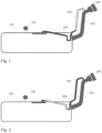
- Figure 1 shows a sealed fuel system for a vehicle comprising a leak detection device according to the prior art, the fuel systems comprising a fuel tank 101, with a filler pipe 102, a venting line 103, used to provide vapor communication between the head of the filler pipe 102 and the fuel tank 101, in order to be able detect a leak at the head 104 of said filler pipe 102 primarily induced by the improper replacement of the fuel cap 104.
- a first pressure sensor 105 on the fuel tank 101 to measure the internal pressure and determine whether or not a leak exists.
- the figure illustrates also the fact that liquid fuel 106 could be present in the venting line 103 by spilling over from either the refueling process or the tank itself.
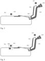
- FIG. 2 shows a sealed fuel system for a vehicle comprising a leak detection device according to the prior art, wherein a fuel cap 204 is improperly placed on the head of a fuel filler pipe 202 of the fuel tank 201 and there is liquid fuel 206 in a venting line 203.
- an internal tank pressure can be achieved that is higher than the threshold pressure defined to ensure the leak integrity of the fuel system due to the hydrostatic pressure the fluid 206 applies on the fuel tank.
- the pressure value measured by a first pressure sensor 205 can falsely indicate that the entire fuel system 201, 202, 203 and205 is leak tight.
Landscapes
- Engineering & Computer Science (AREA)
- Chemical & Material Sciences (AREA)
- Sustainable Development (AREA)
- Mechanical Engineering (AREA)
- Transportation (AREA)
- Combustion & Propulsion (AREA)
- Sustainable Energy (AREA)
- Life Sciences & Earth Sciences (AREA)
- Physics & Mathematics (AREA)
- General Physics & Mathematics (AREA)
- Biomedical Technology (AREA)
- Analytical Chemistry (AREA)
- Health & Medical Sciences (AREA)
- Cooling, Air Intake And Gas Exhaust, And Fuel Tank Arrangements In Propulsion Units (AREA)
- Supplying Secondary Fuel Or The Like To Fuel, Air Or Fuel-Air Mixtures (AREA)
- Examining Or Testing Airtightness (AREA)
Claims (14)
- Système d'alimentation en carburant étanche pour véhicule comprenant un réservoir de carburant (301, 401), un tuyau de remplissage (302, 402), une conduite de ventilation (303, 403) pour la recirculation des vapeurs de carburant du réservoir (301, 401) vers le tuyau de remplissage (302, 402) et un dispositif de détection de fuite, dans lequel le dispositif de détection de fuite comprend :- un premier capteur de pression (305, 405) prévu pour mesurer la pression dans le dôme de vapeur du réservoir de carburant (301, 401),- un second capteur de pression (307, 407), et- un contrôleur,- le tuyau de remplissage dispose d'un moyen d'étanchéité situé à proximité du réservoir de carburant,le circuit d'alimentation en carburant étanche étant caractérisé en ce que :- une partie de la conduite de ventilation (303, 403) forme un puisard, et- le second capteur de pression (307, 407) est prévu pour mesurer la pression dans la conduite de ventilation (303, 403) au-dessus du niveau de liquide le plus élevé possible (306, 406) qui pourrait être présent dans la conduite de ventilation (303, 403) ou pour mesurer la pression dans le tuyau de remplissage (302, 402) au-dessus du niveau de liquide le plus élevé possible (306, 406) qui pourrait être présent dans ledit tuyau de remplissage (302, 402).
- Système d'alimentation en carburant étanche pour un véhicule selon la revendication 1, dans lequel le moyen d'étanchéité est un clapet anti-retour d'entrée.
- Système d'alimentation en carburant étanche pour véhicule selon l'une quelconque des revendications 1 à 2, dans lequel le dispositif de détection de fuite comprend un capteur de température (408) prévu pour mesurer la température dans le dôme de vapeur du réservoir de carburant (301, 401).
- Système d'alimentation en carburant étanche pour un véhicule selon l'une quelconque des revendications 1 à 3, dans lequel la partie de la conduite de ventilation (303, 403) formant un puisard a une forme choisie dans le groupe composé d'une forme en U, d'une forme en V et d'une forme en J, de préférence la partie de la conduite de ventilation formant un puisard a une forme en J.
- Procédé de détection d'une fuite dans un système d'alimentation en carburant étanche d'un véhicule comprenant un réservoir de carburant (301, 401), un tuyau de remplissage (302, 402), une conduite de ventilation (303, 403) pour la recirculation des vapeurs de carburant du réservoir (301, 401) vers le tuyau de remplissage (302, 402), dans lequel une partie de la conduite de ventilation (303, 403) forme un puisard, dans lequel ledit procédé comprend au moins les étapes de :a) mesure et stockage de la pression (P1), et si nécessaire de la température, dans le dôme de vapeur d'un réservoir du réservoir de carburant (301, 401) à des points temporels prédéterminés ;b) mesure de la pression (P2) dans le tuyau de remplissage (302, 402) du système de carburant ou dans la conduite de ventilation (303, 403) du système de carburant au-dessus du niveau de liquide le plus élevé possible qui pourrait être présent dans la conduite de ventilation (303, 403) ou dans le tuyau de remplissage (302, 402) à des points temporels prédéterminés ;c) comparaison de la valeur de pression (P1) dans le dôme de vapeur d'un réservoir du réservoir de carburant (301, 401) et de la valeur de pression (P2) dans le tuyau de remplissage (302, 402) du système de carburant ou dans la conduite de ventilation (303, 403) du système de carburant au-dessus du niveau de liquide le plus élevé possible au même point temporel prédéterminé qui pourrait être présent dans la conduite de ventilation (303, 403) ou dans le tuyau de remplissage (302, 402) ;d) détection d'une fuite à l'aide du résultat obtenu à l'étape c).
- Procédé de détection d'une fuite dans un système d'alimentation en carburant étanche d'un véhicule selon la revendication 5, dans lequel les étapes c) et d) comprennent les étapes de :e) comparaison de la valeur absolue de la différence entre les deux pressions mesurées (P1, P2) à un premier seuil (Th1) ;f) si la valeur absolue de la différence est inférieure au premier seuil (Th1), comparaison des températures et des pressions dans le dôme de vapeur du réservoir de carburant (301, 401) mesurées aux points temporels prédéterminés ;g) si la différence entre les températures mesurées au premier moment et au second moment ultérieure est supérieure à un seuil de température (Th5), calcul d'une pression (Ppredicted) attendue dans le système d'alimentation en carburant au second moment, sur la base de l'évolution de température mesurée entre le premier et le second moment et de la pression obtenue au premier moment, et d'un coefficient qui représente l'évolution naturelle de la pression dans le système de carburant au fil du temps ;h) détection d'une fuite en comparant la pression attendue calculée et la pression obtenue au second moment à au moins un second seuil prédéterminé (Th2).
- Procédé de détection d'une fuite dans un système d'alimentation en carburant étanche d'un véhicule selon l'une quelconque des revendications 5 à 6, dans lequel les étapes c) et d) comprennent les étapes de :i) comparaison de la valeur absolue de la différence entre les deux pressions mesurées (P1, P2) au premier seuil (Th1) ;j) si la valeur absolue de la différence est supérieure au premier seuil (Th1), comparaison de la valeur absolue de la pression (P1) dans le dôme de vapeur d'un réservoir (301, 401) du système d'alimentation en carburant à un troisième seuil (Th3) et comparaison de la valeur absolue de la pression (P2) dans le tuyau de remplissage (302, 402) du système d'alimentation en carburant ou dans la conduite de ventilation (303, 403) du système de carburant au-dessus du niveau de liquide le plus élevé possible qui pourrait être présent dans la conduite de ventilation (303, 403) ou dans le tuyau de remplissage (302, 402), à un quatrième seuil (Th4) ;k) si la valeur absolue de la pression (P1) dans le dôme de vapeur d'un réservoir (301, 401) du système de carburant est inférieure au troisième seuil (Th3), conclusion à l'impossibilité de détecter une fuite ;l) si la valeur absolue de la pression (P2) dans le tuyau de remplissage (302, 402) du système de carburant ou dans la conduite de ventilation (303, 403) du système de carburant au-dessus du niveau de liquide le plus élevé possible qui pourrait être présent dans la conduite de purge (303, 403) ou dans le tuyau de remplissage (302, 402) est supérieure à un quatrième seuil (Th4), conclusion que le système est étanche ;m) si la valeur absolue de la pression (P2) dans le tuyau de remplissage (302, 402) du système de carburant ou dans la conduite de ventilation (303, 403) du système de carburant au-dessus du niveau de liquide le plus élevé possible qui pourrait être présent dans la conduite de purge (303, 403) ou dans le tuyau de remplissage (302, 402) est inférieure au quatrième seuil, conclusion que le système présente une fuite.
- Procédé de détection d'une fuite dans un système d'alimentation en carburant étanche d'un véhicule selon l'une quelconque des revendications 6 à 7, dans lequel le premier seuil (Th1) est défini en tenant compte de la précision et de l'exactitude des deux capteurs de pression.
- Procédé de détection d'une fuite dans un système d'alimentation en carburant étanche d'un véhicule selon la revendication 6, dans lequel le deuxième seuil (Th2) est choisi dans la plage de 5 mbar à 35 mbar et le seuil de température (Th5) est choisi entre 1 ° C et 5 °C, de préférence entre 2 °C et 3 °C.
- Procédé de détection d'une fuite dans un système d'alimentation en carburant étanche d'un véhicule selon la revendication 7, dans lequel le troisième seuil (Th3) est adapté à la pression hydraulique maximale potentielle du liquide dans la partie du puisard de la conduite de ventilation (303, 403) en fonction du signe de la valeur de la pression sur le dôme de vapeur.
- Procédé de détection d'une fuite dans un système d'alimentation en carburant étanche d'un véhicule selon la revendication 7, dans lequel le quatrième seuil (Th4) est défini par rapport à l'exactitude et à la précision du capteur de pression situé dans la conduite de ventilation (303, 403) au-dessus du niveau de liquide le plus élevé possible qui pourrait être présent dans la conduite de ventilation (303, 403) ou situé dans le tuyau de remplissage (302, 402) au-dessus du niveau de liquide le plus élevé possible qui pourrait être présent dans ledit tuyau de remplissage (302, 402).
- Procédé de détection d'une fuite dans un système d'alimentation en carburant étanche d'un véhicule selon l'une quelconque des revendications 7, 8, 10 et 11, dans lequel le troisième et le quatrième seuil (Th3, Th4) sont augmentés de l'évolution de la température entre deux points temporels prédéterminés lorsque ladite évolution est supérieure au seuil de température (Th5).
- Procédé de détection d'une fuite dans un système d'alimentation en carburant étanche d'un véhicule selon l'une quelconque des revendications 6 à 8, dans lequel ledit procédé est démarré lorsque l'évolution de la température mesurée par un capteur de température est supérieure au seuil de température (Th5).
- Procédé de détection d'un dysfonctionnement d'un capteur de pression dans un système d'alimentation en carburant étanche pour un véhicule selon l'une quelconque des revendications 1 à 4, ledit procédé comprenant au moins les étapes de :• mesure de la pression (P1) dans le dôme de vapeur d'un réservoir du réservoir de carburant (301, 401) à des points temporels prédéterminés ;• mesure de la pression (P2) dans le tuyau de remplissage (302, 402) du système de carburant ou dans la conduite de ventilation (303, 403) du système de carburant au-dessus du niveau de liquide le plus élevé possible qui pourrait être présent dans la conduite de ventilation (303, 403) ou dans le tuyau de remplissage (302, 402) à des points temporels prédéterminés ;• comparaison de la valeur de pression (P1) dans le dôme de vapeur d'un réservoir du réservoir de carburant (301, 401) et de la valeur de pression (P2) dans le tuyau de remplissage (302, 402) du système de carburant ou dans la conduite de ventilation (303, 403) du système de carburant au-dessus du niveau de liquide le plus élevé possible qui pourrait être présent dans la conduite de ventilation (303, 403) ou dans le tuyau de remplissage (302, 402) ;• détection du dysfonctionnement d'un capteur de pression.
Applications Claiming Priority (2)
| Application Number | Priority Date | Filing Date | Title |
|---|---|---|---|
| EP19212718 | 2019-11-29 | ||
| PCT/EP2020/083834 WO2021105493A1 (fr) | 2019-11-29 | 2020-11-30 | Système de détection de fuite |
Publications (3)
| Publication Number | Publication Date |
|---|---|
| EP4065400A1 EP4065400A1 (fr) | 2022-10-05 |
| EP4065400B1 true EP4065400B1 (fr) | 2025-07-02 |
| EP4065400B8 EP4065400B8 (fr) | 2025-08-06 |
Family
ID=68762492
Family Applications (1)
| Application Number | Title | Priority Date | Filing Date |
|---|---|---|---|
| EP20811671.5A Active EP4065400B8 (fr) | 2019-11-29 | 2020-11-30 | Système de détection de fuites |
Country Status (6)
| Country | Link |
|---|---|
| US (1) | US12140503B2 (fr) |
| EP (1) | EP4065400B8 (fr) |
| JP (1) | JP7568718B2 (fr) |
| KR (1) | KR102834625B1 (fr) |
| CN (1) | CN114502405A (fr) |
| WO (1) | WO2021105493A1 (fr) |
Families Citing this family (2)
| Publication number | Priority date | Publication date | Assignee | Title |
|---|---|---|---|---|
| US20220200070A1 (en) * | 2020-12-23 | 2022-06-23 | Brunswick Corporation | Marine battery with water ingress and shock detection |
| CN116576910B (zh) * | 2023-04-10 | 2025-10-03 | 宁波格劳博智能工业有限公司 | 一种基于物联网模块和在线监测的智能仪表系统 |
Family Cites Families (15)
| Publication number | Priority date | Publication date | Assignee | Title |
|---|---|---|---|---|
| DE4427688C2 (de) * | 1994-08-04 | 1998-07-23 | Siemens Ag | Verfahren zum Überprüfen der Funktionstüchtigkeit einer Tankentlüftungsanlage für ein Kraftfahrzeug |
| JP2001165006A (ja) | 1999-12-10 | 2001-06-19 | Toyota Motor Corp | 蒸発燃料処理システムの異常診断装置 |
| JP4441498B2 (ja) | 2006-02-24 | 2010-03-31 | 本田技研工業株式会社 | 燃料タンクシステム |
| JP5573467B2 (ja) * | 2010-08-04 | 2014-08-20 | トヨタ自動車株式会社 | 燃料供給系リーク検出方法及び燃料供給系リーク診断装置 |
| US8746215B2 (en) * | 2011-12-02 | 2014-06-10 | Continental Automotive Systems, Inc. | Sample tube structure for automotive fuel tank leak detection |
| US9255553B2 (en) * | 2013-07-10 | 2016-02-09 | Ford Global Technologies, Llc | Leak detection for canister purge valve |
| JP6183605B2 (ja) | 2013-11-15 | 2017-08-23 | 三菱自動車工業株式会社 | 車両の燃料装置 |
| JP6269929B2 (ja) * | 2013-11-15 | 2018-01-31 | 三菱自動車工業株式会社 | 車両の燃料装置 |
| US9145051B2 (en) * | 2013-12-09 | 2015-09-29 | Ford Global Technologies, Llc | Systems and methods for managing bleed emissions in plug-in hybrid electric vehicles |
| DE102014009634A1 (de) * | 2014-06-27 | 2015-12-31 | Audi Ag | Kraftstofftank mit einem Aktivkohlefilter und Verfahren zum Anzeigen des Kraftstofffüllstands im Kraftstofftank mit Signalunterdrückung bei einem kritischen Unterdruck während der Regeneration des Aktivkohlefilters |
| US9745907B2 (en) | 2015-01-27 | 2017-08-29 | Ford Global Technologies, Llc | Systems and methods for inferring fuel vapor canister loading rate |
| DE102015221536A1 (de) * | 2015-11-03 | 2017-05-04 | Volkswagen Aktiengesellschaft | Vorrichtung und Verfahren zur Tankleckagediagnose |
| CN107542598B (zh) | 2016-06-28 | 2019-07-26 | 长城汽车股份有限公司 | 高压燃油蒸发系统及其控制方法、车辆 |
| EP3409936A1 (fr) * | 2017-05-31 | 2018-12-05 | Plastic Omnium Advanced Innovation and Research | Procédé et système permettant de détecter une fuite dans un système de carburant sous pression |
| CN110095228A (zh) * | 2019-05-29 | 2019-08-06 | 深圳市康士柏实业有限公司 | 用于燃油蒸发检测诊断设备的检测与计量校准的测试系统及测试方法 |
-
2020
- 2020-11-30 KR KR1020227016962A patent/KR102834625B1/ko active Active
- 2020-11-30 WO PCT/EP2020/083834 patent/WO2021105493A1/fr not_active Ceased
- 2020-11-30 CN CN202080070959.6A patent/CN114502405A/zh active Pending
- 2020-11-30 US US17/780,386 patent/US12140503B2/en active Active
- 2020-11-30 EP EP20811671.5A patent/EP4065400B8/fr active Active
- 2020-11-30 JP JP2022522051A patent/JP7568718B2/ja active Active
Also Published As
| Publication number | Publication date |
|---|---|
| CN114502405A (zh) | 2022-05-13 |
| KR102834625B1 (ko) | 2025-07-15 |
| JP2023503799A (ja) | 2023-02-01 |
| JP7568718B2 (ja) | 2024-10-16 |
| KR20220106971A (ko) | 2022-08-01 |
| US20230008799A1 (en) | 2023-01-12 |
| WO2021105493A1 (fr) | 2021-06-03 |
| US12140503B2 (en) | 2024-11-12 |
| EP4065400A1 (fr) | 2022-10-05 |
| EP4065400B8 (fr) | 2025-08-06 |
Similar Documents
| Publication | Publication Date | Title |
|---|---|---|
| EP4065400B1 (fr) | Système de détection de fuites | |
| US8630786B2 (en) | Low purge flow vehicle diagnostic tool | |
| CN108407607B (zh) | 一种新式电控燃油系统 | |
| CN110044556A (zh) | 一种汽车燃油蒸发系统密封性的检测装置及检测方法 | |
| US20100098130A1 (en) | High-pressure tank temperature detection system and high-pressure tank system | |
| US20150075267A1 (en) | Fuel tank pressure sensor rationality test for a phev | |
| GB2354331A (en) | Fuel system leak detection | |
| CN110112443B (zh) | 一种燃料电池氢系统的加氢故障诊断方法 | |
| US20130118456A1 (en) | Optimization of tank venting of a fuel tank | |
| CN111608823B (zh) | 炭罐阀开启延迟、油箱泄漏的检测方法及泄漏检测装置 | |
| EP2333290B1 (fr) | Procédé et système pour détecter une fuite dans un réservoir de carburant de véhicule | |
| JP5573467B2 (ja) | 燃料供給系リーク検出方法及び燃料供給系リーク診断装置 | |
| CN207790317U (zh) | 一种新式电控燃油系统 | |
| EP3409936A1 (fr) | Procédé et système permettant de détecter une fuite dans un système de carburant sous pression | |
| US6829555B2 (en) | Method and arrangement for monitoring the emissions during operation of a supply vessel for supplying a volatile medium including a fuel supply tank of a motor vehicle | |
| US6216674B1 (en) | Fuel system vapor integrity testing with temperature compensation | |
| US11118958B2 (en) | System for determining a filling level in a fuel tank | |
| US12241592B2 (en) | Arrangement for a cryogenic system | |
| EP2151565B1 (fr) | Procédé de commande de protection d'injecteur et dispositif de commande d'injection de carburant comportant un rail commun | |
| US8176774B2 (en) | Process and device for testing the mobility of a negative pressure relief valve of the fuel system of a motor vehicle | |
| US10428766B2 (en) | Apparatus and method for filling LPG vehicle with LPG | |
| KR100927349B1 (ko) | Lng 연료용기의 과충전방지방법 | |
| US20130312495A1 (en) | Method and system for quickly detecting an absence of a leak in a fuel system | |
| KR101952717B1 (ko) | 연료레벨 모델링을 이용한 연료캡 열림상태 오판정 방지 장치 및 방법 | |
| KR200310213Y1 (ko) | 차량용 연료탱크의 벤트밸브 테스터기 |
Legal Events
| Date | Code | Title | Description |
|---|---|---|---|
| STAA | Information on the status of an ep patent application or granted ep patent |
Free format text: STATUS: UNKNOWN |
|
| STAA | Information on the status of an ep patent application or granted ep patent |
Free format text: STATUS: THE INTERNATIONAL PUBLICATION HAS BEEN MADE |
|
| PUAI | Public reference made under article 153(3) epc to a published international application that has entered the european phase |
Free format text: ORIGINAL CODE: 0009012 |
|
| STAA | Information on the status of an ep patent application or granted ep patent |
Free format text: STATUS: REQUEST FOR EXAMINATION WAS MADE |
|
| 17P | Request for examination filed |
Effective date: 20220627 |
|
| AK | Designated contracting states |
Kind code of ref document: A1 Designated state(s): AL AT BE BG CH CY CZ DE DK EE ES FI FR GB GR HR HU IE IS IT LI LT LU LV MC MK MT NL NO PL PT RO RS SE SI SK SM TR |
|
| DAV | Request for validation of the european patent (deleted) | ||
| DAX | Request for extension of the european patent (deleted) | ||
| P01 | Opt-out of the competence of the unified patent court (upc) registered |
Effective date: 20230515 |
|
| GRAP | Despatch of communication of intention to grant a patent |
Free format text: ORIGINAL CODE: EPIDOSNIGR1 |
|
| STAA | Information on the status of an ep patent application or granted ep patent |
Free format text: STATUS: GRANT OF PATENT IS INTENDED |
|
| INTG | Intention to grant announced |
Effective date: 20250327 |
|
| GRAS | Grant fee paid |
Free format text: ORIGINAL CODE: EPIDOSNIGR3 |
|
| GRAA | (expected) grant |
Free format text: ORIGINAL CODE: 0009210 |
|
| STAA | Information on the status of an ep patent application or granted ep patent |
Free format text: STATUS: THE PATENT HAS BEEN GRANTED |
|
| GRAT | Correction requested after decision to grant or after decision to maintain patent in amended form |
Free format text: ORIGINAL CODE: EPIDOSNCDEC |
|
| REG | Reference to a national code |
Ref country code: DE Ref legal event code: R081 Ref document number: 602020053916 Country of ref document: DE Owner name: OPMOBILITY C-POWER BELGIUM RESEARCH, BE Free format text: FORMER OWNER: PLASTIC OMNIUM ADVANCED INNOVATION AND RESEARCH, BRUXELLES, BE |
|
| AK | Designated contracting states |
Kind code of ref document: B1 Designated state(s): AL AT BE BG CH CY CZ DE DK EE ES FI FR GB GR HR HU IE IS IT LI LT LU LV MC MK MT NL NO PL PT RO RS SE SI SK SM TR |
|
| REG | Reference to a national code |
Ref country code: GB Ref legal event code: FG4D |
|
| REG | Reference to a national code |
Ref country code: CH Ref legal event code: EP Ref country code: CH Ref legal event code: PK Free format text: BERICHTIGUNG B8 |
|
| RAP4 | Party data changed (patent owner data changed or rights of a patent transferred) |
Owner name: OPMOBILITY C-POWER BELGIUM RESEARCH |
|
| REG | Reference to a national code |
Ref country code: DE Ref legal event code: R096 Ref document number: 602020053916 Country of ref document: DE |
|
| REG | Reference to a national code |
Ref country code: IE Ref legal event code: FG4D |
|
| REG | Reference to a national code |
Ref country code: NL Ref legal event code: MP Effective date: 20250702 |
|
| PG25 | Lapsed in a contracting state [announced via postgrant information from national office to epo] |
Ref country code: PT Free format text: LAPSE BECAUSE OF FAILURE TO SUBMIT A TRANSLATION OF THE DESCRIPTION OR TO PAY THE FEE WITHIN THE PRESCRIBED TIME-LIMIT Effective date: 20251103 |
|
| PG25 | Lapsed in a contracting state [announced via postgrant information from national office to epo] |
Ref country code: NL Free format text: LAPSE BECAUSE OF FAILURE TO SUBMIT A TRANSLATION OF THE DESCRIPTION OR TO PAY THE FEE WITHIN THE PRESCRIBED TIME-LIMIT Effective date: 20250702 |
|
| REG | Reference to a national code |
Ref country code: AT Ref legal event code: MK05 Ref document number: 1808871 Country of ref document: AT Kind code of ref document: T Effective date: 20250702 |
|
| PG25 | Lapsed in a contracting state [announced via postgrant information from national office to epo] |
Ref country code: IS Free format text: LAPSE BECAUSE OF FAILURE TO SUBMIT A TRANSLATION OF THE DESCRIPTION OR TO PAY THE FEE WITHIN THE PRESCRIBED TIME-LIMIT Effective date: 20251102 |
|
| PG25 | Lapsed in a contracting state [announced via postgrant information from national office to epo] |
Ref country code: NO Free format text: LAPSE BECAUSE OF FAILURE TO SUBMIT A TRANSLATION OF THE DESCRIPTION OR TO PAY THE FEE WITHIN THE PRESCRIBED TIME-LIMIT Effective date: 20251002 |
|
| REG | Reference to a national code |
Ref country code: LT Ref legal event code: MG9D |
|
| PG25 | Lapsed in a contracting state [announced via postgrant information from national office to epo] |
Ref country code: AT Free format text: LAPSE BECAUSE OF FAILURE TO SUBMIT A TRANSLATION OF THE DESCRIPTION OR TO PAY THE FEE WITHIN THE PRESCRIBED TIME-LIMIT Effective date: 20250702 |
|
| PG25 | Lapsed in a contracting state [announced via postgrant information from national office to epo] |
Ref country code: FI Free format text: LAPSE BECAUSE OF FAILURE TO SUBMIT A TRANSLATION OF THE DESCRIPTION OR TO PAY THE FEE WITHIN THE PRESCRIBED TIME-LIMIT Effective date: 20250702 |
|
| PG25 | Lapsed in a contracting state [announced via postgrant information from national office to epo] |
Ref country code: HR Free format text: LAPSE BECAUSE OF FAILURE TO SUBMIT A TRANSLATION OF THE DESCRIPTION OR TO PAY THE FEE WITHIN THE PRESCRIBED TIME-LIMIT Effective date: 20250702 |
|
| PG25 | Lapsed in a contracting state [announced via postgrant information from national office to epo] |
Ref country code: GR Free format text: LAPSE BECAUSE OF FAILURE TO SUBMIT A TRANSLATION OF THE DESCRIPTION OR TO PAY THE FEE WITHIN THE PRESCRIBED TIME-LIMIT Effective date: 20251003 |
|
| PG25 | Lapsed in a contracting state [announced via postgrant information from national office to epo] |
Ref country code: CZ Free format text: LAPSE BECAUSE OF FAILURE TO SUBMIT A TRANSLATION OF THE DESCRIPTION OR TO PAY THE FEE WITHIN THE PRESCRIBED TIME-LIMIT Effective date: 20250702 Ref country code: SE Free format text: LAPSE BECAUSE OF FAILURE TO SUBMIT A TRANSLATION OF THE DESCRIPTION OR TO PAY THE FEE WITHIN THE PRESCRIBED TIME-LIMIT Effective date: 20250702 |
|
| PG25 | Lapsed in a contracting state [announced via postgrant information from national office to epo] |
Ref country code: LV Free format text: LAPSE BECAUSE OF FAILURE TO SUBMIT A TRANSLATION OF THE DESCRIPTION OR TO PAY THE FEE WITHIN THE PRESCRIBED TIME-LIMIT Effective date: 20250702 |
|
| PG25 | Lapsed in a contracting state [announced via postgrant information from national office to epo] |
Ref country code: PL Free format text: LAPSE BECAUSE OF FAILURE TO SUBMIT A TRANSLATION OF THE DESCRIPTION OR TO PAY THE FEE WITHIN THE PRESCRIBED TIME-LIMIT Effective date: 20250702 Ref country code: BG Free format text: LAPSE BECAUSE OF FAILURE TO SUBMIT A TRANSLATION OF THE DESCRIPTION OR TO PAY THE FEE WITHIN THE PRESCRIBED TIME-LIMIT Effective date: 20250702 |
|
| PG25 | Lapsed in a contracting state [announced via postgrant information from national office to epo] |
Ref country code: RS Free format text: LAPSE BECAUSE OF FAILURE TO SUBMIT A TRANSLATION OF THE DESCRIPTION OR TO PAY THE FEE WITHIN THE PRESCRIBED TIME-LIMIT Effective date: 20251002 |
|
| PG25 | Lapsed in a contracting state [announced via postgrant information from national office to epo] |
Ref country code: ES Free format text: LAPSE BECAUSE OF FAILURE TO SUBMIT A TRANSLATION OF THE DESCRIPTION OR TO PAY THE FEE WITHIN THE PRESCRIBED TIME-LIMIT Effective date: 20250702 |
|
| PG25 | Lapsed in a contracting state [announced via postgrant information from national office to epo] |
Ref country code: RO Free format text: LAPSE BECAUSE OF FAILURE TO SUBMIT A TRANSLATION OF THE DESCRIPTION OR TO PAY THE FEE WITHIN THE PRESCRIBED TIME-LIMIT Effective date: 20250702 |
|
| PG25 | Lapsed in a contracting state [announced via postgrant information from national office to epo] |
Ref country code: SM Free format text: LAPSE BECAUSE OF FAILURE TO SUBMIT A TRANSLATION OF THE DESCRIPTION OR TO PAY THE FEE WITHIN THE PRESCRIBED TIME-LIMIT Effective date: 20250702 |
|
| PG25 | Lapsed in a contracting state [announced via postgrant information from national office to epo] |
Ref country code: DK Free format text: LAPSE BECAUSE OF FAILURE TO SUBMIT A TRANSLATION OF THE DESCRIPTION OR TO PAY THE FEE WITHIN THE PRESCRIBED TIME-LIMIT Effective date: 20250702 |
|
| PG25 | Lapsed in a contracting state [announced via postgrant information from national office to epo] |
Ref country code: IT Free format text: LAPSE BECAUSE OF FAILURE TO SUBMIT A TRANSLATION OF THE DESCRIPTION OR TO PAY THE FEE WITHIN THE PRESCRIBED TIME-LIMIT Effective date: 20250702 |
|
| PG25 | Lapsed in a contracting state [announced via postgrant information from national office to epo] |
Ref country code: SK Free format text: LAPSE BECAUSE OF FAILURE TO SUBMIT A TRANSLATION OF THE DESCRIPTION OR TO PAY THE FEE WITHIN THE PRESCRIBED TIME-LIMIT Effective date: 20250702 |