EP4065826B1 - Dispositif de post-traitement de gaz d'échappement - Google Patents
Dispositif de post-traitement de gaz d'échappement Download PDFInfo
- Publication number
- EP4065826B1 EP4065826B1 EP20808357.6A EP20808357A EP4065826B1 EP 4065826 B1 EP4065826 B1 EP 4065826B1 EP 20808357 A EP20808357 A EP 20808357A EP 4065826 B1 EP4065826 B1 EP 4065826B1
- Authority
- EP
- European Patent Office
- Prior art keywords
- heating
- heating disk
- honeycomb body
- ceramic
- catalyst
- Prior art date
- Legal status (The legal status is an assumption and is not a legal conclusion. Google has not performed a legal analysis and makes no representation as to the accuracy of the status listed.)
- Active
Links
Images


Classifications
-
- F—MECHANICAL ENGINEERING; LIGHTING; HEATING; WEAPONS; BLASTING
- F01—MACHINES OR ENGINES IN GENERAL; ENGINE PLANTS IN GENERAL; STEAM ENGINES
- F01N—GAS-FLOW SILENCERS OR EXHAUST APPARATUS FOR MACHINES OR ENGINES IN GENERAL; GAS-FLOW SILENCERS OR EXHAUST APPARATUS FOR INTERNAL-COMBUSTION ENGINES
- F01N3/00—Exhaust or silencing apparatus having means for purifying, rendering innocuous, or otherwise treating exhaust
- F01N3/08—Exhaust or silencing apparatus having means for purifying, rendering innocuous, or otherwise treating exhaust for rendering innocuous
- F01N3/10—Exhaust or silencing apparatus having means for purifying, rendering innocuous, or otherwise treating exhaust for rendering innocuous by thermal or catalytic conversion of noxious components of exhaust
- F01N3/18—Exhaust or silencing apparatus having means for purifying, rendering innocuous, or otherwise treating exhaust for rendering innocuous by thermal or catalytic conversion of noxious components of exhaust characterised by methods of operation; Control
- F01N3/20—Exhaust or silencing apparatus having means for purifying, rendering innocuous, or otherwise treating exhaust for rendering innocuous by thermal or catalytic conversion of noxious components of exhaust characterised by methods of operation; Control specially adapted for catalytic conversion
- F01N3/2006—Periodically heating or cooling catalytic reactors, e.g. at cold starting or overheating
-
- F—MECHANICAL ENGINEERING; LIGHTING; HEATING; WEAPONS; BLASTING
- F01—MACHINES OR ENGINES IN GENERAL; ENGINE PLANTS IN GENERAL; STEAM ENGINES
- F01N—GAS-FLOW SILENCERS OR EXHAUST APPARATUS FOR MACHINES OR ENGINES IN GENERAL; GAS-FLOW SILENCERS OR EXHAUST APPARATUS FOR INTERNAL-COMBUSTION ENGINES
- F01N13/00—Exhaust or silencing apparatus characterised by constructional features
- F01N13/009—Exhaust or silencing apparatus characterised by constructional features having two or more separate purifying devices arranged in series
- F01N13/0093—Exhaust or silencing apparatus characterised by constructional features having two or more separate purifying devices arranged in series the purifying devices are of the same type
-
- F—MECHANICAL ENGINEERING; LIGHTING; HEATING; WEAPONS; BLASTING
- F01—MACHINES OR ENGINES IN GENERAL; ENGINE PLANTS IN GENERAL; STEAM ENGINES
- F01N—GAS-FLOW SILENCERS OR EXHAUST APPARATUS FOR MACHINES OR ENGINES IN GENERAL; GAS-FLOW SILENCERS OR EXHAUST APPARATUS FOR INTERNAL-COMBUSTION ENGINES
- F01N13/00—Exhaust or silencing apparatus characterised by constructional features
- F01N13/009—Exhaust or silencing apparatus characterised by constructional features having two or more separate purifying devices arranged in series
- F01N13/0097—Exhaust or silencing apparatus characterised by constructional features having two or more separate purifying devices arranged in series the purifying devices are arranged in a single housing
-
- F—MECHANICAL ENGINEERING; LIGHTING; HEATING; WEAPONS; BLASTING
- F01—MACHINES OR ENGINES IN GENERAL; ENGINE PLANTS IN GENERAL; STEAM ENGINES
- F01N—GAS-FLOW SILENCERS OR EXHAUST APPARATUS FOR MACHINES OR ENGINES IN GENERAL; GAS-FLOW SILENCERS OR EXHAUST APPARATUS FOR INTERNAL-COMBUSTION ENGINES
- F01N3/00—Exhaust or silencing apparatus having means for purifying, rendering innocuous, or otherwise treating exhaust
- F01N3/08—Exhaust or silencing apparatus having means for purifying, rendering innocuous, or otherwise treating exhaust for rendering innocuous
- F01N3/10—Exhaust or silencing apparatus having means for purifying, rendering innocuous, or otherwise treating exhaust for rendering innocuous by thermal or catalytic conversion of noxious components of exhaust
- F01N3/18—Exhaust or silencing apparatus having means for purifying, rendering innocuous, or otherwise treating exhaust for rendering innocuous by thermal or catalytic conversion of noxious components of exhaust characterised by methods of operation; Control
- F01N3/20—Exhaust or silencing apparatus having means for purifying, rendering innocuous, or otherwise treating exhaust for rendering innocuous by thermal or catalytic conversion of noxious components of exhaust characterised by methods of operation; Control specially adapted for catalytic conversion
- F01N3/2006—Periodically heating or cooling catalytic reactors, e.g. at cold starting or overheating
- F01N3/2013—Periodically heating or cooling catalytic reactors, e.g. at cold starting or overheating using electric or magnetic heating means
- F01N3/2026—Periodically heating or cooling catalytic reactors, e.g. at cold starting or overheating using electric or magnetic heating means directly electrifying the catalyst substrate, i.e. heating the electrically conductive catalyst substrate by joule effect
-
- F—MECHANICAL ENGINEERING; LIGHTING; HEATING; WEAPONS; BLASTING
- F01—MACHINES OR ENGINES IN GENERAL; ENGINE PLANTS IN GENERAL; STEAM ENGINES
- F01N—GAS-FLOW SILENCERS OR EXHAUST APPARATUS FOR MACHINES OR ENGINES IN GENERAL; GAS-FLOW SILENCERS OR EXHAUST APPARATUS FOR INTERNAL-COMBUSTION ENGINES
- F01N3/00—Exhaust or silencing apparatus having means for purifying, rendering innocuous, or otherwise treating exhaust
- F01N3/08—Exhaust or silencing apparatus having means for purifying, rendering innocuous, or otherwise treating exhaust for rendering innocuous
- F01N3/10—Exhaust or silencing apparatus having means for purifying, rendering innocuous, or otherwise treating exhaust for rendering innocuous by thermal or catalytic conversion of noxious components of exhaust
- F01N3/24—Exhaust or silencing apparatus having means for purifying, rendering innocuous, or otherwise treating exhaust for rendering innocuous by thermal or catalytic conversion of noxious components of exhaust characterised by constructional aspects of converting apparatus
- F01N3/28—Construction of catalytic reactors
- F01N3/2803—Construction of catalytic reactors characterised by structure, by material or by manufacturing of catalyst support
- F01N3/2807—Metal other than sintered metal
-
- F—MECHANICAL ENGINEERING; LIGHTING; HEATING; WEAPONS; BLASTING
- F01—MACHINES OR ENGINES IN GENERAL; ENGINE PLANTS IN GENERAL; STEAM ENGINES
- F01N—GAS-FLOW SILENCERS OR EXHAUST APPARATUS FOR MACHINES OR ENGINES IN GENERAL; GAS-FLOW SILENCERS OR EXHAUST APPARATUS FOR INTERNAL-COMBUSTION ENGINES
- F01N3/00—Exhaust or silencing apparatus having means for purifying, rendering innocuous, or otherwise treating exhaust
- F01N3/08—Exhaust or silencing apparatus having means for purifying, rendering innocuous, or otherwise treating exhaust for rendering innocuous
- F01N3/10—Exhaust or silencing apparatus having means for purifying, rendering innocuous, or otherwise treating exhaust for rendering innocuous by thermal or catalytic conversion of noxious components of exhaust
- F01N3/24—Exhaust or silencing apparatus having means for purifying, rendering innocuous, or otherwise treating exhaust for rendering innocuous by thermal or catalytic conversion of noxious components of exhaust characterised by constructional aspects of converting apparatus
- F01N3/28—Construction of catalytic reactors
- F01N3/2803—Construction of catalytic reactors characterised by structure, by material or by manufacturing of catalyst support
- F01N3/2807—Metal other than sintered metal
- F01N3/281—Metallic honeycomb monoliths made of stacked or rolled sheets, foils or plates
-
- F—MECHANICAL ENGINEERING; LIGHTING; HEATING; WEAPONS; BLASTING
- F01—MACHINES OR ENGINES IN GENERAL; ENGINE PLANTS IN GENERAL; STEAM ENGINES
- F01N—GAS-FLOW SILENCERS OR EXHAUST APPARATUS FOR MACHINES OR ENGINES IN GENERAL; GAS-FLOW SILENCERS OR EXHAUST APPARATUS FOR INTERNAL-COMBUSTION ENGINES
- F01N3/00—Exhaust or silencing apparatus having means for purifying, rendering innocuous, or otherwise treating exhaust
- F01N3/08—Exhaust or silencing apparatus having means for purifying, rendering innocuous, or otherwise treating exhaust for rendering innocuous
- F01N3/10—Exhaust or silencing apparatus having means for purifying, rendering innocuous, or otherwise treating exhaust for rendering innocuous by thermal or catalytic conversion of noxious components of exhaust
- F01N3/24—Exhaust or silencing apparatus having means for purifying, rendering innocuous, or otherwise treating exhaust for rendering innocuous by thermal or catalytic conversion of noxious components of exhaust characterised by constructional aspects of converting apparatus
- F01N3/28—Construction of catalytic reactors
- F01N3/2803—Construction of catalytic reactors characterised by structure, by material or by manufacturing of catalyst support
- F01N3/2825—Ceramics
- F01N3/2828—Ceramic multi-channel monoliths, e.g. honeycombs
-
- F—MECHANICAL ENGINEERING; LIGHTING; HEATING; WEAPONS; BLASTING
- F01—MACHINES OR ENGINES IN GENERAL; ENGINE PLANTS IN GENERAL; STEAM ENGINES
- F01N—GAS-FLOW SILENCERS OR EXHAUST APPARATUS FOR MACHINES OR ENGINES IN GENERAL; GAS-FLOW SILENCERS OR EXHAUST APPARATUS FOR INTERNAL-COMBUSTION ENGINES
- F01N3/00—Exhaust or silencing apparatus having means for purifying, rendering innocuous, or otherwise treating exhaust
- F01N3/08—Exhaust or silencing apparatus having means for purifying, rendering innocuous, or otherwise treating exhaust for rendering innocuous
- F01N3/10—Exhaust or silencing apparatus having means for purifying, rendering innocuous, or otherwise treating exhaust for rendering innocuous by thermal or catalytic conversion of noxious components of exhaust
- F01N3/24—Exhaust or silencing apparatus having means for purifying, rendering innocuous, or otherwise treating exhaust for rendering innocuous by thermal or catalytic conversion of noxious components of exhaust characterised by constructional aspects of converting apparatus
- F01N3/28—Construction of catalytic reactors
- F01N3/2839—Arrangements for mounting catalyst support in housing, e.g. with means for compensating thermal expansion or vibration
- F01N3/2842—Arrangements for mounting catalyst support in housing, e.g. with means for compensating thermal expansion or vibration specially adapted for monolithic supports, e.g. of honeycomb type
-
- F—MECHANICAL ENGINEERING; LIGHTING; HEATING; WEAPONS; BLASTING
- F01—MACHINES OR ENGINES IN GENERAL; ENGINE PLANTS IN GENERAL; STEAM ENGINES
- F01N—GAS-FLOW SILENCERS OR EXHAUST APPARATUS FOR MACHINES OR ENGINES IN GENERAL; GAS-FLOW SILENCERS OR EXHAUST APPARATUS FOR INTERNAL-COMBUSTION ENGINES
- F01N3/00—Exhaust or silencing apparatus having means for purifying, rendering innocuous, or otherwise treating exhaust
- F01N3/08—Exhaust or silencing apparatus having means for purifying, rendering innocuous, or otherwise treating exhaust for rendering innocuous
- F01N3/10—Exhaust or silencing apparatus having means for purifying, rendering innocuous, or otherwise treating exhaust for rendering innocuous by thermal or catalytic conversion of noxious components of exhaust
- F01N3/24—Exhaust or silencing apparatus having means for purifying, rendering innocuous, or otherwise treating exhaust for rendering innocuous by thermal or catalytic conversion of noxious components of exhaust characterised by constructional aspects of converting apparatus
- F01N3/28—Construction of catalytic reactors
- F01N3/2839—Arrangements for mounting catalyst support in housing, e.g. with means for compensating thermal expansion or vibration
- F01N3/2853—Arrangements for mounting catalyst support in housing, e.g. with means for compensating thermal expansion or vibration using mats or gaskets between catalyst body and housing
-
- F—MECHANICAL ENGINEERING; LIGHTING; HEATING; WEAPONS; BLASTING
- F01—MACHINES OR ENGINES IN GENERAL; ENGINE PLANTS IN GENERAL; STEAM ENGINES
- F01N—GAS-FLOW SILENCERS OR EXHAUST APPARATUS FOR MACHINES OR ENGINES IN GENERAL; GAS-FLOW SILENCERS OR EXHAUST APPARATUS FOR INTERNAL-COMBUSTION ENGINES
- F01N2240/00—Combination or association of two or more different exhaust treating devices, or of at least one such device with an auxiliary device, not covered by indexing codes F01N2230/00 or F01N2250/00, one of the devices being
- F01N2240/16—Combination or association of two or more different exhaust treating devices, or of at least one such device with an auxiliary device, not covered by indexing codes F01N2230/00 or F01N2250/00, one of the devices being an electric heater, i.e. a resistance heater
-
- F—MECHANICAL ENGINEERING; LIGHTING; HEATING; WEAPONS; BLASTING
- F01—MACHINES OR ENGINES IN GENERAL; ENGINE PLANTS IN GENERAL; STEAM ENGINES
- F01N—GAS-FLOW SILENCERS OR EXHAUST APPARATUS FOR MACHINES OR ENGINES IN GENERAL; GAS-FLOW SILENCERS OR EXHAUST APPARATUS FOR INTERNAL-COMBUSTION ENGINES
- F01N2330/00—Structure of catalyst support or particle filter
- F01N2330/02—Metallic plates or honeycombs, e.g. superposed or rolled-up corrugated or otherwise deformed sheet metal
-
- F—MECHANICAL ENGINEERING; LIGHTING; HEATING; WEAPONS; BLASTING
- F01—MACHINES OR ENGINES IN GENERAL; ENGINE PLANTS IN GENERAL; STEAM ENGINES
- F01N—GAS-FLOW SILENCERS OR EXHAUST APPARATUS FOR MACHINES OR ENGINES IN GENERAL; GAS-FLOW SILENCERS OR EXHAUST APPARATUS FOR INTERNAL-COMBUSTION ENGINES
- F01N2330/00—Structure of catalyst support or particle filter
- F01N2330/06—Ceramic, e.g. monoliths
-
- Y—GENERAL TAGGING OF NEW TECHNOLOGICAL DEVELOPMENTS; GENERAL TAGGING OF CROSS-SECTIONAL TECHNOLOGIES SPANNING OVER SEVERAL SECTIONS OF THE IPC; TECHNICAL SUBJECTS COVERED BY FORMER USPC CROSS-REFERENCE ART COLLECTIONS [XRACs] AND DIGESTS
- Y02—TECHNOLOGIES OR APPLICATIONS FOR MITIGATION OR ADAPTATION AGAINST CLIMATE CHANGE
- Y02T—CLIMATE CHANGE MITIGATION TECHNOLOGIES RELATED TO TRANSPORTATION
- Y02T10/00—Road transport of goods or passengers
- Y02T10/10—Internal combustion engine [ICE] based vehicles
- Y02T10/12—Improving ICE efficiencies
Definitions
- the invention relates to a device for treating exhaust gases of an internal combustion engine, with a heating disk arranged in a housing and with a main catalyst arranged in the housing downstream of the heating disk in the flow direction, wherein the heating disk and the main catalyst can be flowed through along the flow direction along a plurality of flow channels.
- Electric heating devices are used, among other things, to heat the exhaust gas flowing in exhaust systems and the catalysts arranged in the exhaust system.
- Known examples include electric heating catalysts that have a honeycomb body through which the exhaust gas can flow and also a heating device, such as a heating conductor.
- a heating catalyst or a heating disk is supported by suitable support means against a so-called supporting catalyst.
- a supporting catalyst can be, for example, an oxidation catalyst, an SCR catalyst or another catalyst suitable for exhaust gas aftertreatment.
- These main catalysts are also regularly formed by coated metallic honeycomb bodies.
- the DE 44 34 673 A1 discloses a device for the catalytic conversion of exhaust gases in an exhaust system, in particular for an exhaust system of an internal combustion engine, preferably for gasoline engines.
- the device comprises at least two honeycomb bodies arranged in an outer jacket tube, through which an exhaust gas can flow one after the other, wherein the honeycomb bodies are mechanically connected to one another by means of support elements projecting into the honeycomb bodies.
- One of the honeycomb bodies is arranged at a distance from the outer jacket tube and has at least two shells connected to the jacket surface of the honeycomb body, each of which is connected to an electrical power connection.
- the device has electrically insulating connecting elements, wherein each connecting element is connected at one end to the shell and at its other end to the adjacent honeycomb body.
- the DE 196 02 266 A1 discloses an internal combustion engine exhaust gas catalyst with a heating zone designed as a metal carrier catalyst, downstream of which a further catalyst body is provided.
- the heating zone extends only over a partial area of the exhaust gas flow cross-section, so that only a small amount of heat capacity needs to be heated with the electrical heating energy provided.
- a nozzle-like constriction of the flow cross-section is provided upstream of the heating zone.
- the heating zone can be surrounded by a supporting catalyst body.
- the DE 10 2009 018182 A1 discloses an electrically heatable honeycomb body with channels, comprising at least one heating disk with at least a first layer stack made of an electrically conductive material and a second layer stack made of an electrically conductive material, wherein the first layer stack and the second layer stack are intertwined with one another and electrically insulated from one another, wherein the first layer stack forms a first current path for conducting an electrical current for a first heating circuit and the second layer stack forms a second current path for conducting an electrical current for a second heating circuit.
- the WO 2004/112433 A1 discloses a method of manufacturing an electric heater, the method comprising the steps of laminating a corrugated strip and a flat strip each made of a thin metal plate to form a heating line, applying a filler metal or a sheet-like brazing foil to the heating line, and brazing in a vacuum furnace.
- the method uses a template to maintain a predetermined shape of the heating line.
- the JP H07 54644 A discloses a method for reducing energy consumption by partially heating a catalyst carrier.
- a heating part is provided which is connected to the catalyst carrier so as to be partially electrified.
- a metallic carrier forming a short-circuit passage in the radial direction is attached to the position of a first catalyst device, and only the metallic carrier is connected to the power supply such as a battery.
- the short-circuit channel is connected to the end face on the upstream side, and the electrical resistance of the short-circuit channel is smaller than that of a tape-like body for forming a honeycomb structure, so that a large current flows to the short-circuit channel.
- the object of the present invention is to provide a device which exploits the advantages of a metallic heating catalyst and at the same time minimizes the disadvantages due to the need for additional electrical insulation.
- One embodiment of the invention relates to a device for treating exhaust gases from an internal combustion engine, with a heating disk arranged in a housing and with a main catalyst arranged in the housing downstream of the heating disk in the flow direction, wherein the heating disk and the main catalyst can be flowed through along the flow direction along several flow channels, wherein the heating disk is formed by a metallic honeycomb body and the main catalyst is formed from a ceramic honeycomb body which is fixed relative to the housing by means of a fixing means, such as a swelling mat or a bearing mat, wherein the heating disk is electrically contacted by means of an electrical feedthrough which is led through the housing from the outside to the inside, wherein the heating disk is inserted into a ceramic half-shell.
- a housing can preferably be a casing tube into which the respective elements, such as the heating disk and the main catalyst, are inserted.
- the jacket pipe is part of the exhaust gas line and the exhaust gas can flow through it along a main flow direction.
- the heating disk is preferably formed from a metallic honeycomb body which has a plurality of flow channels through which flow can pass along a main flow direction.
- the main catalyst is advantageously made of a ceramic material and also has a plurality of flow channels through which flow can pass.
- the main catalyst can be, for example, an oxidation catalyst, an SCR catalyst or another catalyst which is regularly used for exhaust gas aftertreatment.
- the coating of the ceramic and the material composition of the ceramic can be varied for the corresponding application.
- the fixing means can preferably be formed by a swelling mat or a storage mat.
- a swelling mat is a fiber fabric that is used to securely fix the ceramic honeycomb body in the casing tube. This includes preventing relative movement relative to the casing tube and also preventing mechanical damage to the honeycomb body.
- This mat can be designed in such a way that it changes its volume during the usual heat treatments and other processing steps, in particular it swells up, in order to enable secure fixing.
- suitably dimensioned storage mats can be used that do not experience any change in volume.
- One or more electronic feedthroughs can be provided for electrical contact.
- Various concepts for temperature-safe and stable, long-lasting feedthroughs of electrical conductors are already known in the state of the art.
- a ceramic half-shell can in particular be a structure through which fluid can flow. This can, for example, be porous or also have a large number of openings that allow fluid to flow through.
- the half-shell can preferably be pot-shaped and have a base area through which fluid can flow and side walls that run at least partially in the circumferential direction.
- the heating disk can in turn be inserted into the ceramic half-shell or pressed into it.
- the ceramic half-shell can extend over the entire cross-section of the heating disc or can only run in the form of a band-shaped web under the heating disc.
- connection of the heating disc with the ceramic half-shell can be made, for example, via mandrels which are formed as part of the ceramic half-shell and engage in flow channels of the heating disc.
- the outer diameter of the heating disk is smaller than the inner diameter of the housing, with an annular air gap being formed between the housing and the heating disk.
- the air gap serves in particular to electrically insulate the heating disk from the casing tube in order to prevent short circuits and other unwanted current flows.
- the heating disk is supported by several support pins relative to the main catalyst and is spaced apart from it.
- Support pins can particularly preferably be made of metal or of ceramic. Due to the ceramic main catalyst, additional electrical insulation between the metal heating disk and the main catalyst, which is connected to the jacket tube, is not necessary. Therefore, the most suitable support pins for the individual application can be used.
- the support pins can be pressed into the heating disk and soldered to it. The component produced from the heating disk and support pins can then be inserted into the main catalyst. Alternatively, the support pins can also be attached to the main catalyst first and the metal heating disk can be pressed on afterwards.
- the support pins can be clamped, glued, soldered or screwed to the main catalyst and/or the heating disk.
- the ceramic half-shell is fixed to the housing by means of a fixing means, such as a swelling mat or a bearing mat.
- the ceramic holding shell can also be supported by a swelling mat in relation to the casing tube.
- the casing tube preferably has receiving areas for this purpose, which are used to receive the fixing agent and the corresponding honeycomb body or the ceramic half-shell.
- the heating disk formed by a metallic honeycomb body is pressed into the ceramic half-shell.
- the ceramic half-shell does not block the exhaust gas flow, for example by covering the flow channels of the heating disk.
- the surface of the ceramic half-shell located on the gas outlet side of the heating disk has a grid-like structure, which ideally has openings that coincide with the flow channels of the heating disk.
- the ceramic half-shell can, for example, have locking elements with which the heating disk is fixed after being pressed into the ceramic half-shell.
- a material connection between the heating disk and the ceramic half-shell is also possible.
- the honeycomb body of the main catalyst has a recess on one of its end faces that is adapted to the shape of the heating disk, with the heating disk being pressed into the recess in the honeycomb body.
- This is particularly advantageous in order to enable the heating disk to be integrated into the ceramic main catalyst.
- the recess can be created directly when the honeycomb body is shaped or subsequently by a machining process, for example milling.
- the flow channels of the heating disk should not be covered by the structure of the main catalyst. Ideally, the flow channels of the heating disk and the main catalyst are congruent with each other.
- the main catalyst can have mandrels which engage in individual flow channels of the heating disk for the purpose of fixing.
- the honeycomb body of the main catalyst has at least one bore extending in the radial direction in the region of the recess, wherein the electrical contact of the heating disc is led through this hole to the heating disc.
- Such a hole is necessary to lead the electrical conductor to the metal heating disk.
- a corresponding number of holes must be provided on the honeycomb body of the main catalyst.
- support pins are guided through individual flow channels formed in the honeycomb body of the main catalyst from the gas inlet side to the gas outlet side of the honeycomb body.
- the support pins are advantageously fixed relative to the gas inlet side and/or the gas outlet side.
- Support pins that run completely along the flow channels through the ceramic honeycomb body of the main catalyst offer particularly high stability due to the long distance they cover. These can be fixed to the honeycomb body using screw connections or clamping plates, for example, which are attached to the gas inlet side and the gas outlet side.
- the support pins protrude beyond the gas inlet side of the honeycomb body of the main catalyst and the heating disk is pressed onto the protruding areas of the support pins.
- the heating disk is supported by means of support pins against a metallic honeycomb body serving as a supporting catalyst, the supporting catalyst being connected to the inner surface of the housing on its outer circumference.
- the heating disk is thus fixed to the casing tube via the connection to the supporting catalyst.
- the support pins for connecting the heating disk to the supporting catalyst are electrically conductive, it must be noted that an electrical current flow is generated towards the casing tube. This can be prevented by using suitably insulated support pins.
- the Figure 1 shows a sectional view, showing a casing tube 1 serving as a housing, a heating disk 2, a main catalyst 3, an electrical feedthrough 4, and support pins 5 which space the heating disk 2 from the main catalyst 3.
- the Figure 1 shows a general embodiment which is not part of the invention.
- the heating disk 2 is formed by a metallic honeycomb body.
- the main catalyst 3 is a ceramic honeycomb body, which Depending on the intended use, it can be coated with a suitable coating, for example.
- the main catalyst is fixed to the casing tube 1 by means of a swelling mat 6. In addition to its fixing effect, the swelling mat 6 can also have an electrical insulating effect.
- the electrical feedthrough 4 in the example of Figure 1 Two electrical feedthroughs 4 are provided, used for electrical contact with the heating disk 2.
- the electrical feedthrough 4 forms a temperature-resistant guide for an electrical conductor that is electrically insulated from the jacket tube 1.
- the electrical feedthrough 4, which is formed by a sleeve, for example, can preferably be welded to the jacket tube 1.
- the support pins 5 can be made from a metallic material or from a ceramic material.
- the support pins 5 are preferably inserted into individual flow channels of the honeycomb bodies of the heating disk 2 and the main catalyst 3. To further secure the connection, the support pins 5 can be soldered to the honeycomb bodies, for example.
- the core task of the support pins 5 is to fix the heating disk 2 within the casing tube 1 so that the electrically contacted heating disk 2 does not come into electrically conductive contact with the casing tube 1.
- FIG. 2 shows a device according to the invention for exhaust gas aftertreatment. Identical parts are given the same reference numerals as Figure 1 provided.
- the main catalyst 3 is also supported against the interior of the casing tube 7 using a swelling mat 6.
- the casing tube 7 has shoulders 8 on its inner surface, which serve to axially fix the honeycomb bodies 3, 2 and the swelling mats 6, 9 used.
- the shoulders can be arranged completely circumferentially or only in sections.
- the heating disk 2 is inserted into a ceramic half-shell 11.
- the heating disk 2 is fixed by means of mandrels 10, which can engage in individual flow channels of the heating disk 2 or rest on the outer circumference of the heating disk 2.
- the heating disk 2 can form a press fit with the ceramic half-shell 11, whereby it is fixed in the half-shell.
- the ceramic half-shell 11 is fixed between the shoulders 8 by means of a second swelling mat 9.
- An air gap is formed between the heating disk 2 and the ceramic honeycomb body 3, whereby the two elements are spaced apart from one another in the axial direction.
- the electrical feedthrough 4 is guided in the radial direction through the jacket tube 7, the swelling mat 9 and, if applicable, through the ceramic half-shell 11 in order to contact the heating disk 2.
- Figure 3 shows a further arrangement not belonging to the invention, wherein the heating disk 2 is inserted into a recess 12 in the ceramic honeycomb body 13.
- the honeycomb body 13 is supported by means of a swelling mat 6 relative to the casing tube 1.
- the electrical feedthrough 4 is guided through the casing tube 1, the swelling mat 6 and the honeycomb body 13 to the heating disk 2.
- the recess 12 is made in the front side of the honeycomb body 13 and can form a press fit with the heating disc 2 or have other fixing means for the heating disc 2 in the honeycomb body 13. As with Figure 2 Mandrels which engage in the flow channels of the heating disc 2 can also be provided.
- the Figure 4 shows a structure not belonging to the invention with a ceramic honeycomb body 3, which is supported by a swelling mat 6 opposite the casing tube 1.
- the heating disk 2 is electrically contacted by means of the electrical feedthrough or feedthroughs 4.
- Support pins 14 are shown here, which are guided through the ceramic honeycomb body 3.
- the support pins 14 are guided along individual flow channels from the gas inlet side to the gas outlet side.
- the support pins 14 are fixed to the ceramic honeycomb body 3 with locking devices 15, for example screwed or clamped.
- the heating disk 2 is then pressed onto the protruding end regions of the support pins 14, whereby the heating disk 2 is fixed at a distance from the ceramic honeycomb body 2 and the inner wall of the jacket tube 1.
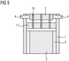
- Figure 5 shows a further alternative embodiment not belonging to the invention with the ceramic honeycomb body 3, the swelling mat 6, the jacket tube 1, the heating disk 2 and the electrical feedthroughs 4, as already shown in previous figures.
- the heating disk 2 is connected to another metallic honeycomb body 17 by means of support pins 16.
- the other metallic honeycomb body 17 forms a so-called supporting catalyst.
- the supporting catalyst serves to fix the heating disk 2 within the casing tube 1.
- the supporting catalyst 17 has a larger diameter than the heating disk 2 and is in particular large enough to support itself against the inner wall of the jacket tube 1.
- the heating disk 2 is spaced axially from the supporting catalyst 17, which in turn is spaced from the ceramic honeycomb body 3.
- the supporting catalyst can, for example, be soldered to the jacket tube to ensure secure fixation.
Landscapes
- Chemical & Material Sciences (AREA)
- Engineering & Computer Science (AREA)
- Chemical Kinetics & Catalysis (AREA)
- Combustion & Propulsion (AREA)
- Mechanical Engineering (AREA)
- General Engineering & Computer Science (AREA)
- Health & Medical Sciences (AREA)
- Toxicology (AREA)
- Ceramic Engineering (AREA)
- Exhaust Gas After Treatment (AREA)
Claims (4)
- Dispositif de traitement de gaz d'échappement d'un moteur à combustion interne, avec un disque chauffant (2) agencé dans un boîtier (1) et avec un catalyseur principal (3, 13) agencé dans le boîtier (1) en aval du disque chauffant (2) dans la direction d'écoulement, le disque chauffant (2) et le catalyseur principal (3, 13) pouvant être traversés par un écoulement le long de la direction d'écoulement le long de plusieurs canaux d'écoulement, le disque chauffant (2) étant formé par un corps métallique en nid d'abeilles et le catalyseur principal (3, 13) étant formé par un corps céramique en nid d'abeilles qui est fixé par rapport au boîtier (1) au moyen d'un moyen de fixation (6), le disque chauffant (2) étant mis en contact électrique au moyen d'un passage électrique (4) qui est guidé à travers le boîtier (1) de l'extérieur vers l'intérieur, caractérisé en ce que le disque chauffant (2) est inséré dans une demi-coque céramique (11).
- Dispositif selon la revendication 1, caractérisé en ce que la demi-coque céramique (11) est fixée par rapport au boîtier (1) au moyen d'un moyen de fixation (9).
- Dispositif selon l'une quelconque des revendications 1 ou 2 précédentes, caractérisé en ce que le disque chauffant (2) formé par un corps métallique en nid d'abeilles est enfoncé dans la demi-coque céramique (11).
- Dispositif selon l'une quelconque des revendications précédentes, caractérisé en ce que le corps en nid d'abeilles du catalyseur principal (13) présente sur l'une de ses faces frontales un évidement (12) adapté à la forme du disque chauffant (2), le disque chauffant (2) étant enfoncé dans l'évidement (12) dans le corps en nid d'abeilles (13).
Applications Claiming Priority (2)
| Application Number | Priority Date | Filing Date | Title |
|---|---|---|---|
| DE102019218354.9A DE102019218354A1 (de) | 2019-11-27 | 2019-11-27 | Vorrichtung zur Abgasnachbehandlung |
| PCT/EP2020/082362 WO2021104936A1 (fr) | 2019-11-27 | 2020-11-17 | Dispositif de post-traitement de gaz d'échappement |
Publications (2)
| Publication Number | Publication Date |
|---|---|
| EP4065826A1 EP4065826A1 (fr) | 2022-10-05 |
| EP4065826B1 true EP4065826B1 (fr) | 2025-01-08 |
Family
ID=73476129
Family Applications (1)
| Application Number | Title | Priority Date | Filing Date |
|---|---|---|---|
| EP20808357.6A Active EP4065826B1 (fr) | 2019-11-27 | 2020-11-17 | Dispositif de post-traitement de gaz d'échappement |
Country Status (5)
| Country | Link |
|---|---|
| US (1) | US11802501B2 (fr) |
| EP (1) | EP4065826B1 (fr) |
| CN (1) | CN114761677A (fr) |
| DE (1) | DE102019218354A1 (fr) |
| WO (1) | WO2021104936A1 (fr) |
Families Citing this family (1)
| Publication number | Priority date | Publication date | Assignee | Title |
|---|---|---|---|---|
| DE102022212260A1 (de) * | 2022-11-17 | 2024-05-23 | Vitesco Technologies GmbH | Vorrichtung zur Aufheizung von Abgasen |
Citations (1)
| Publication number | Priority date | Publication date | Assignee | Title |
|---|---|---|---|---|
| US20070056263A1 (en) * | 2005-08-11 | 2007-03-15 | Michael Roach | Device and method for heating exhaust gas |
Family Cites Families (14)
| Publication number | Priority date | Publication date | Assignee | Title |
|---|---|---|---|---|
| US5140813A (en) * | 1990-10-31 | 1992-08-25 | Whittenberger William A | Composite catalytic converter |
| US5525309A (en) * | 1991-01-31 | 1996-06-11 | Emitec Gesellschaft Fuer Emissionstechnologie Mbh | Honeycomb body with a plurality of disks braced against one another |
| EP0569403B1 (fr) * | 1991-01-31 | 1995-06-07 | Emitec Gesellschaft für Emissionstechnologie mbH | Corps en nid d'abeilles ayant une pluralite de disques appuyes les uns sur les autres |
| JP2913868B2 (ja) * | 1991-03-08 | 1999-06-28 | トヨタ自動車株式会社 | 内燃機関の排ガス浄化装置 |
| US5254840A (en) * | 1991-12-12 | 1993-10-19 | Corning Incorporated | Mounting for metal honeycomb structures |
| JPH0754644A (ja) * | 1992-12-21 | 1995-02-28 | Toyota Motor Corp | 電気加熱式触媒装置 |
| DE4434673A1 (de) * | 1994-09-28 | 1996-04-04 | Emitec Emissionstechnologie | Elektrisch beheizbarer Katalysator |
| DE19602266A1 (de) | 1996-01-23 | 1997-07-24 | Bayerische Motoren Werke Ag | Elektrisch beheizbarer Abgas-Katalysator einer Brennkraftmaschine |
| DE10254764A1 (de) * | 2002-11-22 | 2004-06-03 | Emitec Gesellschaft Für Emissionstechnologie Mbh | Abgasanlage |
| KR100534081B1 (ko) * | 2003-06-12 | 2005-12-07 | 일진전기 주식회사 | 지그를 이용한 전기히터 제작방법 및 그 전기히터 |
| CN1680689A (zh) * | 2004-04-08 | 2005-10-12 | 中国环境科学研究院 | 用于内燃机排气净化装置的电加热器 |
| DE102007010758A1 (de) * | 2007-03-06 | 2008-09-11 | Emitec Gesellschaft Für Emissionstechnologie Mbh | Elektrisch beheizbarer Wabenkörper und Verfahren zu dessen Betrieb |
| DE102009018182A1 (de) | 2009-04-22 | 2010-10-28 | Emitec Gesellschaft Für Emissionstechnologie Mbh | Mehrstufig beheizbarer Wabenkörper |
| DE102011110664A1 (de) * | 2011-08-19 | 2013-02-21 | Emitec Gesellschaft Für Emissionstechnologie Mbh | Vorrichtung zur Behandlung von Abgasen |
-
2019
- 2019-11-27 DE DE102019218354.9A patent/DE102019218354A1/de active Pending
-
2020
- 2020-11-17 US US17/780,316 patent/US11802501B2/en active Active
- 2020-11-17 CN CN202080082400.5A patent/CN114761677A/zh active Pending
- 2020-11-17 WO PCT/EP2020/082362 patent/WO2021104936A1/fr not_active Ceased
- 2020-11-17 EP EP20808357.6A patent/EP4065826B1/fr active Active
Patent Citations (1)
| Publication number | Priority date | Publication date | Assignee | Title |
|---|---|---|---|---|
| US20070056263A1 (en) * | 2005-08-11 | 2007-03-15 | Michael Roach | Device and method for heating exhaust gas |
Also Published As
| Publication number | Publication date |
|---|---|
| CN114761677A (zh) | 2022-07-15 |
| WO2021104936A1 (fr) | 2021-06-03 |
| US11802501B2 (en) | 2023-10-31 |
| US20220412242A1 (en) | 2022-12-29 |
| DE102019218354A1 (de) | 2021-05-27 |
| EP4065826A1 (fr) | 2022-10-05 |
Similar Documents
| Publication | Publication Date | Title |
|---|---|---|
| EP3964696B1 (fr) | Chauffage de gaz d'échappement | |
| EP2150688B1 (fr) | Dispositif comprenant un corps alvéolaire volumineux à chauffage électrique | |
| EP0581784B1 (fr) | Corps en nid d'abeille pouvant etre chauffe electriquement | |
| EP3685025B1 (fr) | Plaque chauffante pour être chauffée électriquement pour post-traitement de gaz d'échappement | |
| EP2836687B1 (fr) | Connection électrique de plusieurs couches en tôle d'un corps en nid d'abeille et corps en nid d'abeille correspondant | |
| EP3207229B1 (fr) | Structure porteur, dispositif pour le traitement de gaz d'échappement et son procédé de fabrication | |
| DE102021205198A1 (de) | Vorrichtung zur Erwärmung eines Abgasstroms | |
| EP4314508B1 (fr) | Dispositif de traitement des gaz d'échappement et son procédé de production | |
| EP4174294B1 (fr) | Unité de chauffage pour un système d'échappement d'un moteur à combustion interne | |
| DE102011110664A1 (de) | Vorrichtung zur Behandlung von Abgasen | |
| EP4065826B1 (fr) | Dispositif de post-traitement de gaz d'échappement | |
| EP4223991B1 (fr) | Dispositif de chauffage électrique de gaz d'échappement | |
| EP3864262B1 (fr) | Dispositif pour traitement des gaz d'échappement | |
| DE102022130442A1 (de) | Heizelement für Abgasleitung | |
| EP4069952B1 (fr) | Broche de support pour convertisseur catalytique à disque chauffant électrique | |
| EP3864263B1 (fr) | Dispositif pour traitement des gaz d'échappement | |
| DE102021006655A1 (de) | Heizvorrichtung sowie Verfahren zur Herstellung einer Heizvorrichtung | |
| EP4144964B1 (fr) | Système d'échappement | |
| DE102022111864B4 (de) | Heizvorrichtung | |
| DE102019219150B4 (de) | Vorrichtung zur Abgasnachbehandlung und Verfahren zur Herstellung dieser | |
| DE102022114107A1 (de) | Abgasheizer | |
| DE102022206145A1 (de) | Vorrichtung zur Erwärmung von in einer Abgasleitung strömbaren Abgas | |
| DE102022111865A1 (de) | Heizvorrichtung | |
| DE102021132931A1 (de) | Abgasheizanordnung für eine Abgasanlage einer Brennkraftmaschine | |
| DE102021113760A1 (de) | Heizvorrichtung sowie Verfahren zur Herstellung einer Heizvorrichtung |
Legal Events
| Date | Code | Title | Description |
|---|---|---|---|
| STAA | Information on the status of an ep patent application or granted ep patent |
Free format text: STATUS: UNKNOWN |
|
| STAA | Information on the status of an ep patent application or granted ep patent |
Free format text: STATUS: THE INTERNATIONAL PUBLICATION HAS BEEN MADE |
|
| PUAI | Public reference made under article 153(3) epc to a published international application that has entered the european phase |
Free format text: ORIGINAL CODE: 0009012 |
|
| STAA | Information on the status of an ep patent application or granted ep patent |
Free format text: STATUS: REQUEST FOR EXAMINATION WAS MADE |
|
| 17P | Request for examination filed |
Effective date: 20220627 |
|
| AK | Designated contracting states |
Kind code of ref document: A1 Designated state(s): AL AT BE BG CH CY CZ DE DK EE ES FI FR GB GR HR HU IE IS IT LI LT LU LV MC MK MT NL NO PL PT RO RS SE SI SK SM TR |
|
| DAV | Request for validation of the european patent (deleted) | ||
| DAX | Request for extension of the european patent (deleted) | ||
| P01 | Opt-out of the competence of the unified patent court (upc) registered |
Effective date: 20230530 |
|
| STAA | Information on the status of an ep patent application or granted ep patent |
Free format text: STATUS: EXAMINATION IS IN PROGRESS |
|
| 17Q | First examination report despatched |
Effective date: 20231122 |
|
| GRAP | Despatch of communication of intention to grant a patent |
Free format text: ORIGINAL CODE: EPIDOSNIGR1 |
|
| STAA | Information on the status of an ep patent application or granted ep patent |
Free format text: STATUS: GRANT OF PATENT IS INTENDED |
|
| INTG | Intention to grant announced |
Effective date: 20240710 |
|
| GRAS | Grant fee paid |
Free format text: ORIGINAL CODE: EPIDOSNIGR3 |
|
| GRAA | (expected) grant |
Free format text: ORIGINAL CODE: 0009210 |
|
| STAA | Information on the status of an ep patent application or granted ep patent |
Free format text: STATUS: THE PATENT HAS BEEN GRANTED |
|
| AK | Designated contracting states |
Kind code of ref document: B1 Designated state(s): AL AT BE BG CH CY CZ DE DK EE ES FI FR GB GR HR HU IE IS IT LI LT LU LV MC MK MT NL NO PL PT RO RS SE SI SK SM TR |
|
| REG | Reference to a national code |
Ref country code: GB Ref legal event code: FG4D Free format text: NOT ENGLISH |
|
| REG | Reference to a national code |
Ref country code: CH Ref legal event code: EP |
|
| REG | Reference to a national code |
Ref country code: DE Ref legal event code: R096 Ref document number: 502020010172 Country of ref document: DE |
|
| REG | Reference to a national code |
Ref country code: IE Ref legal event code: FG4D Free format text: LANGUAGE OF EP DOCUMENT: GERMAN |
|
| REG | Reference to a national code |
Ref country code: DE Ref legal event code: R081 Ref document number: 502020010172 Country of ref document: DE Owner name: SCHAEFFLER TECHNOLOGIES AG & CO. KG, DE Free format text: FORMER OWNER: VITESCO TECHNOLOGIES GMBH, 93055 REGENSBURG, DE |
|
| RAP2 | Party data changed (patent owner data changed or rights of a patent transferred) |
Owner name: SCHAEFFLER TECHNOLOGIES AG & CO. KG |
|
| REG | Reference to a national code |
Ref country code: LT Ref legal event code: MG9D |
|
| REG | Reference to a national code |
Ref country code: NL Ref legal event code: MP Effective date: 20250108 |
|
| PG25 | Lapsed in a contracting state [announced via postgrant information from national office to epo] |
Ref country code: NL Free format text: LAPSE BECAUSE OF FAILURE TO SUBMIT A TRANSLATION OF THE DESCRIPTION OR TO PAY THE FEE WITHIN THE PRESCRIBED TIME-LIMIT Effective date: 20250108 |
|
| PG25 | Lapsed in a contracting state [announced via postgrant information from national office to epo] |
Ref country code: RS Free format text: LAPSE BECAUSE OF FAILURE TO SUBMIT A TRANSLATION OF THE DESCRIPTION OR TO PAY THE FEE WITHIN THE PRESCRIBED TIME-LIMIT Effective date: 20250408 |
|
| PG25 | Lapsed in a contracting state [announced via postgrant information from national office to epo] |
Ref country code: FI Free format text: LAPSE BECAUSE OF FAILURE TO SUBMIT A TRANSLATION OF THE DESCRIPTION OR TO PAY THE FEE WITHIN THE PRESCRIBED TIME-LIMIT Effective date: 20250108 |
|
| PG25 | Lapsed in a contracting state [announced via postgrant information from national office to epo] |
Ref country code: PL Free format text: LAPSE BECAUSE OF FAILURE TO SUBMIT A TRANSLATION OF THE DESCRIPTION OR TO PAY THE FEE WITHIN THE PRESCRIBED TIME-LIMIT Effective date: 20250108 |
|
| PG25 | Lapsed in a contracting state [announced via postgrant information from national office to epo] |
Ref country code: ES Free format text: LAPSE BECAUSE OF FAILURE TO SUBMIT A TRANSLATION OF THE DESCRIPTION OR TO PAY THE FEE WITHIN THE PRESCRIBED TIME-LIMIT Effective date: 20250108 |
|
| PG25 | Lapsed in a contracting state [announced via postgrant information from national office to epo] |
Ref country code: NO Free format text: LAPSE BECAUSE OF FAILURE TO SUBMIT A TRANSLATION OF THE DESCRIPTION OR TO PAY THE FEE WITHIN THE PRESCRIBED TIME-LIMIT Effective date: 20250408 Ref country code: IS Free format text: LAPSE BECAUSE OF FAILURE TO SUBMIT A TRANSLATION OF THE DESCRIPTION OR TO PAY THE FEE WITHIN THE PRESCRIBED TIME-LIMIT Effective date: 20250508 |
|
| PG25 | Lapsed in a contracting state [announced via postgrant information from national office to epo] |
Ref country code: HR Free format text: LAPSE BECAUSE OF FAILURE TO SUBMIT A TRANSLATION OF THE DESCRIPTION OR TO PAY THE FEE WITHIN THE PRESCRIBED TIME-LIMIT Effective date: 20250108 |
|
| PG25 | Lapsed in a contracting state [announced via postgrant information from national office to epo] |
Ref country code: PT Free format text: LAPSE BECAUSE OF FAILURE TO SUBMIT A TRANSLATION OF THE DESCRIPTION OR TO PAY THE FEE WITHIN THE PRESCRIBED TIME-LIMIT Effective date: 20250508 Ref country code: LV Free format text: LAPSE BECAUSE OF FAILURE TO SUBMIT A TRANSLATION OF THE DESCRIPTION OR TO PAY THE FEE WITHIN THE PRESCRIBED TIME-LIMIT Effective date: 20250108 |
|
| PG25 | Lapsed in a contracting state [announced via postgrant information from national office to epo] |
Ref country code: GR Free format text: LAPSE BECAUSE OF FAILURE TO SUBMIT A TRANSLATION OF THE DESCRIPTION OR TO PAY THE FEE WITHIN THE PRESCRIBED TIME-LIMIT Effective date: 20250409 Ref country code: BG Free format text: LAPSE BECAUSE OF FAILURE TO SUBMIT A TRANSLATION OF THE DESCRIPTION OR TO PAY THE FEE WITHIN THE PRESCRIBED TIME-LIMIT Effective date: 20250108 |
|
| PG25 | Lapsed in a contracting state [announced via postgrant information from national office to epo] |
Ref country code: SE Free format text: LAPSE BECAUSE OF FAILURE TO SUBMIT A TRANSLATION OF THE DESCRIPTION OR TO PAY THE FEE WITHIN THE PRESCRIBED TIME-LIMIT Effective date: 20250108 |
|
| PG25 | Lapsed in a contracting state [announced via postgrant information from national office to epo] |
Ref country code: SM Free format text: LAPSE BECAUSE OF FAILURE TO SUBMIT A TRANSLATION OF THE DESCRIPTION OR TO PAY THE FEE WITHIN THE PRESCRIBED TIME-LIMIT Effective date: 20250108 |
|
| REG | Reference to a national code |
Ref country code: DE Ref legal event code: R097 Ref document number: 502020010172 Country of ref document: DE |
|
| PG25 | Lapsed in a contracting state [announced via postgrant information from national office to epo] |
Ref country code: DK Free format text: LAPSE BECAUSE OF FAILURE TO SUBMIT A TRANSLATION OF THE DESCRIPTION OR TO PAY THE FEE WITHIN THE PRESCRIBED TIME-LIMIT Effective date: 20250108 |
|
| PG25 | Lapsed in a contracting state [announced via postgrant information from national office to epo] |
Ref country code: CZ Free format text: LAPSE BECAUSE OF FAILURE TO SUBMIT A TRANSLATION OF THE DESCRIPTION OR TO PAY THE FEE WITHIN THE PRESCRIBED TIME-LIMIT Effective date: 20250108 Ref country code: EE Free format text: LAPSE BECAUSE OF FAILURE TO SUBMIT A TRANSLATION OF THE DESCRIPTION OR TO PAY THE FEE WITHIN THE PRESCRIBED TIME-LIMIT Effective date: 20250108 |
|
| PG25 | Lapsed in a contracting state [announced via postgrant information from national office to epo] |
Ref country code: RO Free format text: LAPSE BECAUSE OF FAILURE TO SUBMIT A TRANSLATION OF THE DESCRIPTION OR TO PAY THE FEE WITHIN THE PRESCRIBED TIME-LIMIT Effective date: 20250108 |
|
| PG25 | Lapsed in a contracting state [announced via postgrant information from national office to epo] |
Ref country code: SK Free format text: LAPSE BECAUSE OF FAILURE TO SUBMIT A TRANSLATION OF THE DESCRIPTION OR TO PAY THE FEE WITHIN THE PRESCRIBED TIME-LIMIT Effective date: 20250108 |
|
| PLBE | No opposition filed within time limit |
Free format text: ORIGINAL CODE: 0009261 |
|
| STAA | Information on the status of an ep patent application or granted ep patent |
Free format text: STATUS: NO OPPOSITION FILED WITHIN TIME LIMIT |
|
| 26N | No opposition filed |
Effective date: 20251009 |
|
| PGFP | Annual fee paid to national office [announced via postgrant information from national office to epo] |
Ref country code: DE Payment date: 20251130 Year of fee payment: 6 |
|
| PGFP | Annual fee paid to national office [announced via postgrant information from national office to epo] |
Ref country code: FR Payment date: 20251126 Year of fee payment: 6 |
|
| PG25 | Lapsed in a contracting state [announced via postgrant information from national office to epo] |
Ref country code: IT Free format text: LAPSE BECAUSE OF FAILURE TO SUBMIT A TRANSLATION OF THE DESCRIPTION OR TO PAY THE FEE WITHIN THE PRESCRIBED TIME-LIMIT Effective date: 20250108 |