EP4065901B1 - Vorrichtung zum produzieren von heisser flüssigkeit - Google Patents
Vorrichtung zum produzieren von heisser flüssigkeit Download PDFInfo
- Publication number
- EP4065901B1 EP4065901B1 EP20820512.0A EP20820512A EP4065901B1 EP 4065901 B1 EP4065901 B1 EP 4065901B1 EP 20820512 A EP20820512 A EP 20820512A EP 4065901 B1 EP4065901 B1 EP 4065901B1
- Authority
- EP
- European Patent Office
- Prior art keywords
- tank
- circuit
- heat exchanger
- inlet
- pump
- Prior art date
- Legal status (The legal status is an assumption and is not a legal conclusion. Google has not performed a legal analysis and makes no representation as to the accuracy of the status listed.)
- Active
Links
Images





Classifications
-
- F—MECHANICAL ENGINEERING; LIGHTING; HEATING; WEAPONS; BLASTING
- F24—HEATING; RANGES; VENTILATING
- F24H—FLUID HEATERS, e.g. WATER OR AIR HEATERS, HAVING HEAT-GENERATING MEANS, e.g. HEAT PUMPS, IN GENERAL
- F24H1/00—Water heaters, e.g. boilers, continuous-flow heaters or water-storage heaters
- F24H1/18—Water-storage heaters
- F24H1/181—Construction of the tank
-
- F—MECHANICAL ENGINEERING; LIGHTING; HEATING; WEAPONS; BLASTING
- F24—HEATING; RANGES; VENTILATING
- F24H—FLUID HEATERS, e.g. WATER OR AIR HEATERS, HAVING HEAT-GENERATING MEANS, e.g. HEAT PUMPS, IN GENERAL
- F24H1/00—Water heaters, e.g. boilers, continuous-flow heaters or water-storage heaters
- F24H1/18—Water-storage heaters
- F24H1/20—Water-storage heaters with immersed heating elements, e.g. electric elements or furnace tubes
- F24H1/201—Water-storage heaters with immersed heating elements, e.g. electric elements or furnace tubes using electric energy supply
- F24H1/202—Water-storage heaters with immersed heating elements, e.g. electric elements or furnace tubes using electric energy supply with resistances
-
- F—MECHANICAL ENGINEERING; LIGHTING; HEATING; WEAPONS; BLASTING
- F24—HEATING; RANGES; VENTILATING
- F24H—FLUID HEATERS, e.g. WATER OR AIR HEATERS, HAVING HEAT-GENERATING MEANS, e.g. HEAT PUMPS, IN GENERAL
- F24H15/00—Control of fluid heaters
- F24H15/20—Control of fluid heaters characterised by control inputs
- F24H15/212—Temperature of the water
-
- F—MECHANICAL ENGINEERING; LIGHTING; HEATING; WEAPONS; BLASTING
- F24—HEATING; RANGES; VENTILATING
- F24H—FLUID HEATERS, e.g. WATER OR AIR HEATERS, HAVING HEAT-GENERATING MEANS, e.g. HEAT PUMPS, IN GENERAL
- F24H15/00—Control of fluid heaters
- F24H15/20—Control of fluid heaters characterised by control inputs
- F24H15/238—Flow rate
-
- F—MECHANICAL ENGINEERING; LIGHTING; HEATING; WEAPONS; BLASTING
- F24—HEATING; RANGES; VENTILATING
- F24H—FLUID HEATERS, e.g. WATER OR AIR HEATERS, HAVING HEAT-GENERATING MEANS, e.g. HEAT PUMPS, IN GENERAL
- F24H15/00—Control of fluid heaters
- F24H15/30—Control of fluid heaters characterised by control outputs; characterised by the components to be controlled
- F24H15/305—Control of valves
- F24H15/31—Control of valves of valves having only one inlet port and one outlet port, e.g. flow rate regulating valves
-
- F—MECHANICAL ENGINEERING; LIGHTING; HEATING; WEAPONS; BLASTING
- F24—HEATING; RANGES; VENTILATING
- F24H—FLUID HEATERS, e.g. WATER OR AIR HEATERS, HAVING HEAT-GENERATING MEANS, e.g. HEAT PUMPS, IN GENERAL
- F24H15/00—Control of fluid heaters
- F24H15/30—Control of fluid heaters characterised by control outputs; characterised by the components to be controlled
- F24H15/335—Control of pumps, e.g. on-off control
-
- F—MECHANICAL ENGINEERING; LIGHTING; HEATING; WEAPONS; BLASTING
- F24—HEATING; RANGES; VENTILATING
- F24H—FLUID HEATERS, e.g. WATER OR AIR HEATERS, HAVING HEAT-GENERATING MEANS, e.g. HEAT PUMPS, IN GENERAL
- F24H15/00—Control of fluid heaters
- F24H15/30—Control of fluid heaters characterised by control outputs; characterised by the components to be controlled
- F24H15/335—Control of pumps, e.g. on-off control
- F24H15/34—Control of the speed of pumps
-
- F—MECHANICAL ENGINEERING; LIGHTING; HEATING; WEAPONS; BLASTING
- F24—HEATING; RANGES; VENTILATING
- F24H—FLUID HEATERS, e.g. WATER OR AIR HEATERS, HAVING HEAT-GENERATING MEANS, e.g. HEAT PUMPS, IN GENERAL
- F24H9/00—Details
- F24H9/18—Arrangement or mounting of grates or heating means
- F24H9/1809—Arrangement or mounting of grates or heating means for water heaters
- F24H9/1818—Arrangement or mounting of electric heating means
-
- F—MECHANICAL ENGINEERING; LIGHTING; HEATING; WEAPONS; BLASTING
- F24—HEATING; RANGES; VENTILATING
- F24H—FLUID HEATERS, e.g. WATER OR AIR HEATERS, HAVING HEAT-GENERATING MEANS, e.g. HEAT PUMPS, IN GENERAL
- F24H9/00—Details
- F24H9/20—Arrangement or mounting of control or safety devices
- F24H9/2007—Arrangement or mounting of control or safety devices for water heaters
- F24H9/2014—Arrangement or mounting of control or safety devices for water heaters using electrical energy supply
- F24H9/2021—Storage heaters
Definitions
- the present invention relates to a device for producing hot fluid, in particular domestic hot water.
- Such a device for producing hot fluid is known as illustrated in the patent DE-4206074 .
- the design of current devices does not give complete satisfaction in terms of longevity, maintenance and performance of the device.
- the quantity of hot water that can be produced is generally found to be low compared to the quantity of water stored.
- the control of the temperature of the fluid to be heated at the start of the draw is often imperfect.
- An aim of the invention is to propose a device for producing hot fluid, the design of which allows, for an equal volume of the tank with a tank of a hot fluid production device of the state of the art, to optimize the quantity of hot fluid produced in relation to the quantity of liquid stored in the tank without affecting the quality of the control of the temperature of the fluid to be heated at the start of drawing.
- the position of the heat exchange zone of the heat exchanger outside the tank makes it possible to free up the useful space of the tank to store liquid there and the production of the part of the tank in contact with the liquid in synthetic material makes it possible to increase the heating temperature of said liquid, these two characteristics contributing to the optimization of the quantity of hot fluid produced relative to the amount of liquid stored in the tank, without compromising the longevity of the device or its ease of maintenance.
- the design of the device can eliminate the need for a thermostatic mixer at the point of use of the hot fluid.
- thermosiphon phenomena In addition, the presence of a controlled valve on the loop circulation circuit between the tank and the primary circuit of the heat exchanger allows thermosiphon phenomena to be perfectly controlled.
- the device comprises a clock and the control unit is configured to control the actuation of the drive member in moving the valve in the direction of opening the valve in parallel with the control of starting the pump and configured to control the actuation of the drive member in moving the valve in the direction of closing the valve in the stopped state of the pump after stopping the pump for a predetermined period of time.
- thermosiphon allows a thermosiphon to be initially authorized and then this phenomenon to be stopped in order to keep the heat exchanger as cold as possible to make the temperature of the fluid to be heated reliable at the start of the draw.
- the pump is a variable flow pump and the device comprises means for regulating the flow rate of said pump, these means for regulating the flow rate of the pump comprising a flow meter arranged, preferably, at the inlet of the secondary circuit, and at least two temperature probes, at least one of which is arranged on the loop circulation circuit between the tank and the primary circuit of the heat exchanger, and the control unit is configured to control the pump at least as a function of the data provided by the temperature probes and the flow meter.
- the means of regulation make it possible to offer very good reactivity and instantaneous production of hot water at a temperature close to the desired set temperature.
- the flow meter can be in a other location, the presence of the flow meter at the secondary circuit input can make it possible to control the operation of the pump only when a flow is detected, which limits wear on the pump and limits the energy consumption of the device.
- the device comprises, at the inlet of the secondary circuit, in the zone of connection of the inlet of the secondary circuit to at least one source of fluid to be heated, a conduit arranged at least partially in the thickness of the tank, this conduit called the inlet conduit coupling at one end to the inlet of the secondary circuit of the heat exchanger dividing on the opposite end side of connection to at least one source of fluid to be heated into two branches, one equipped with a shut-off member, the other with a flow meter.
- This arrangement makes it possible to supply the heat exchanger with cold fluid from the network of fluid to be heated or with hot fluid from a hot fluid distribution network to allow immediate hot fluid output during a draw-off.
- the loop circulation circuit between the tank and the primary circuit of the heat exchanger comprises a forward branch arranged between the outlet of the tank and the inlet of the primary circuit and a return branch arranged between the outlet of the primary circuit and the inlet of the tank, the pump and the valve being arranged, preferably, on the forward branch of the loop circulation circuit.
- the tank is equipped with a liquid filling orifice for the tank, this filling orifice being connected by a closable fluid connection to the portion of the secondary circuit extending between the inlet of the secondary circuit and the heat exchange zone between the primary and secondary circuits of the heat exchanger.
- the closable fluid connection is provided at the filling orifice with a connection piece to the tank, this connection piece being provided with a vent, an overflow orifice and an additional orifice acting as an overflow or vent depending on the filling level of the tank.
- This arrangement makes it possible to reliably prevent a mixing the "dead" water contained in the tank with the tank filling liquid from a network.
- the connecting part to the tank equipping the closable fluid connection at the filling orifice is provided with a closure member mounted to move between a closed position and an open position and returned under the effect of its own weight to the closed position.
- this closure member is a pivoting valve. The presence of such a closure member at this level makes it possible to prevent the formation of condensation at the level of the cover of the casing.
- the tank is equipped with a so-called lower level sensor and a so-called upper level sensor arranged at different heights in the tank
- the closable fluid connection is provided with a closing member equipped with an electrical control circuit and the electrical control circuit is configured to switch from the closed state corresponding to the open position of the closing member to the open state corresponding to the closed position of the closing member at least in the activated state of the upper level sensor. Thanks to this configuration, the risks of overflowing of the tank are reduced.
- the outlet of the tank connectable to the inlet of the primary circuit is arranged in the upper third of the interior volume of the tank and the inlet of the tank connectable to the outlet of the primary circuit is arranged in the lower third of the interior volume of the tank. Thanks to this arrangement of the inlet and outlet of the tank, the temperature stratification, also called thermal stratification, of the liquid inside the tank is maintained. This allows better control of the temperature of the liquid at the outlet of the tank.
- At least part of the heating system is housed in the tank and the inlet of the tank connectable to the outlet of the primary circuit of the heat exchanger opens into the tank at a level lower than the level occupied by the part of the heating system housed in the tank.
- the tank comprises, in the lower half of the tank, on the outer surface of the tank a reservation inside which the heat exchanger which is a counter-current heat exchanger, preferably with plates, is able to be housed to extend at least partially inside the overall size of the tank.
- This positioning of the heat exchanger in the lower part of the tank offers an advantage in terms of thermosiphon of the heat exchanger and in terms of maintaining the thermal stratification of the liquid contained in the tank.
- the heat exchanger is, in the state connected to the tank, arranged at a level lower than the level occupied by the inlet of the tank connectable to the outlet of the primary circuit of said heat exchanger.
- This arrangement allows for emptying by thermosiphon of the hot liquid that may be contained in the primary circuit of the heat exchanger, which allows for better control of the temperature of the fluid to be heated at the start of the draw. Indeed, it has been found that if hot liquid stagnates in the primary circuit of the heat exchanger, it disrupts the control of the temperature of the fluid to be heated at the start of the draw. Finally, part of the hot liquid stagnating in the forward branch of the loop circuit between the tank and the heat exchanger can be reintroduced into the tank to be used during a subsequent draw.
- the tank comprises an enclosure, a casing at least partially surrounding the enclosure and an insulator arranged between the enclosure and the casing.
- At least part of the heating system is housed in the tank and the thickness of the tank taken between the external face of the casing and the internal face of the enclosure is in the part of the tank extending above the part of the heating system housed inside the tank at least locally greater than that of the thickness of the tank extending below the part of the heating system housed inside the tank.
- the reinforcement of the insulation in the upper part of the tank makes it possible to keep the upper part of the tank as warm as possible.
- At least the heat exchanger, the pump, which is variable flow, and the valve with its displacement drive member, which is preferably a motor, form a ready-to-install assembly. This results in easier maintenance and manufacturing.
- the heating system comprises at least one electrical resistor housed inside the tank
- the tank comprises, at the level of the, or at least one of the electrical resistors, two facing orifices, one arranged in the enclosure, the other in the casing, these orifices being connected by a housing body with a pierced bottom forming a sheath for connecting said orifices together, this housing body extending at least partially inside the enclosure
- the electrical resistor is in the form of an elongated body provided with a seal threaded onto the electrical resistor, this seal in sealed bearing contact with the electrical resistor sealingly closing the piercing in the bottom of the housing body in the state in which said piercing is passed through by the electrical resistor.
- the invention relates to a device 1 for producing fluid, in particular hot liquid.
- the device 1 is a device for producing hot water, preferably sanitary, for instantaneous production of hot water, but such a device can be applied to the production of other types of hot liquids depending on the source of liquid to be heated chosen without departing from the scope of the invention.
- This hot liquid production device can be a domestic hot water production device suitable for installation in any type of construction.
- the liquid contained in tank 2 is therefore heated to supply the primary circuit 8 of the heat exchanger before returning to the tank.
- the cold water from the sanitary water circuit of the building which is a pressurized water circuit, supplies the secondary circuit 9 of the heat exchanger 7.
- This cold sanitary water is heated at the level of the heat exchanger 7 by exchanging calories with the primary circuit 8 of said exchanger before being distributed to any of the water points in the building.
- the liquid contained in the tank is said to be dead. In fact, this liquid is not intended to be distributed but simply to heat the cold water in the sanitary water network.
- the liquid receiving tank 2 which may be water or an aqueous solution, or any other type of liquid, is a tank with a vertical axis. Indeed, this tank 2 has a face forming a bottom supporting the ground and a top face, the longitudinal axis of the tank 2 passing through said faces. In the example shown, the tank is of generally parallelepiped shape.
- At least the so-called inner part of the tank 2 capable of being in contact with the filling liquid of the tank 2 is made of synthetic material, in particular polyolefin such as polypropylene.
- This tank 2 stores the liquid at pressure atmospheric.
- At least one safety vent 36 which will be described in more detail below may be provided to prevent any overpressure inside the tank 2.
- the tank 2 comprises an enclosure 51, a casing 52 at least partially surrounding the enclosure 51, and an insulator 53 arranged between the enclosure 51 and the casing 52.
- the liquid is contained inside the enclosure 51.
- the enclosure 51 is therefore equipped with the liquid inlet 3 and outlet 4 with the liquid outlet 4 arranged at a level higher than the level occupied by the liquid inlet 3 of the tank.
- This enclosure 51 is made of synthetic material, preferably polyolefin.
- the casing 52 is here formed of a body open on the top and a cover for closing the body.
- the enclosure 51 is thus inserted into the casing 52 which, in the closed state, completely surrounds the enclosure 51.
- the insulator 53 is, for its part, formed by a foam, for example, injected into the envelope in the inserted state of the enclosure in the envelope 52 in the space left free between the exterior of the enclosure 51 and the interior of the envelope 52.
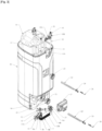
- the tank 2 comprises, in the lower half of the tank 2, on the outer surface of the tank 2, a reservation 16 inside which the heat exchanger 7 is able to be housed to extend at least partially inside the overall dimensions of the tank 2.
- This reservation 16 is formed by a recess of said tank 2 formed in the side wall of the tank at the level of the area of the side wall of the tank adjoining the bottom of the tank.
- This reservation thus forms a housing for the heat exchanger external to the tank which can be closed by a cover.
- the heat exchanger 7 is thus arranged outside the tank in the lower part of the tank 2, that is to say at the level of the lower half of the tank 2, near the bottom of the tank.
- This heat exchanger 7 is, in the state connected to the tank 2, arranged at a level lower than the level occupied by the inlet 3 of the tank 2 connectable to the outlet 8B of the primary circuit 8 of said heat exchanger 7.
- the heat exchanger 7 is a counter-current exchanger, in particular a plate exchanger, with the plates extending horizontally, that is to say substantially parallel to the face forming the base supporting the ground of the tank.
- the inputs and outputs of the primary and secondary circuits of the heat exchanger are, in the example shown, arranged on the same face of the block containing the plates of the exchanger 7.
- the loop circulation circuit 11 between the tank 2 and the primary circuit 8 of the heat exchanger 7 comprises a forward branch 11A arranged between the outlet 4 of the tank 2 and the inlet 8A of the primary circuit 8 and a return branch 11B arranged between the outlet 8B of the primary circuit 8 and the inlet 3 of the tank, the pump 12 and the valve 31 being here arranged on the forward branch 11A of the loop circulation circuit 11, which constitutes a preferred solution although the pump 12 and the valve 31 can also be arranged on the return branch.
- the forward branch 11A is formed by a conduit, one end of which is permanently fixed to the inlet 3 of the tank 2.
- This conduit has a length of conduit embedded in the insulation of the tank followed by a length of conduit which extends into the reservation 16 of the tank 2 to be connected to the inlet 8A of the primary circuit 8 of the heat exchanger 7.
- the liquid circulates in the primary circuit 8 of the heat exchanger before exiting the heat exchanger at the outlet 8B of the heat exchanger. Again, a conduit connects this outlet 8B of the heat exchanger to the inlet 3 of the tank enclosure and forms the return branch 11B of the circuit 11.
- connection between the inlet 3 of the tank and the outlet 8B of the primary circuit of the exchanger is of shorter length than the connection between the outlet 4 of the tank and the inlet 8A of the primary circuit 8 of the heat exchanger 7.
- the outlet 4 of the tank connectable to the inlet 8A of the primary circuit 8 is arranged in the upper third of the interior volume of the tank 2 and the inlet of the tank 2 connectable to the outlet 8B of the primary circuit 8 is arranged in the lower third of the interior volume of the tank 2, it being understood that the upper third and the lower third are taken by reference to the total height of the interior volume of the enclosure of the tank, this height being taken between the highest point of the internal volume and the lowest point of the internal volume in the state positioned on the ground of the tank resting by its bottom face on a horizontal surface.
- the enclosure of the tank has a maximum filling level and the outlet of the tank is generally arranged below this maximum filling level in the upper third of the tank.
- the inlet 3 of the tank 2 connectable to the outlet 8B of the primary circuit 8 of the heat exchanger opens into the tank 2 at a level lower than the level occupied by the part 6 of the heating system housed in the tank 2.
- the aim is to extract liquid from the tank at the hot zone of the tank and to reintroduce liquid into the tank at the cold zone of the tank to avoid a disturbance of the thermal stratification which would cause turbulence generating a loss in volume of the usable hot liquid volume.
- the pump 12 which is used for this loop circulation of the liquid between the tank and the heat exchanger is a variable flow pump 12, such as a pump with a "brushless" motor.
- the presence of the valve 31 and the adjustment of the pump flow rate make it possible to respect the temperature setpoint of the domestic hot water to be distributed. This temperature setpoint is predefined.
- the device 1 comprises a clock 171 whose data can be addressed to the control unit 17.
- the control unit 17 is configured to control the actuation of the drive member 32 for moving the valve 31, i.e. the drive motor for moving the valve 31, in the direction of opening the valve 31 in parallel with the control of starting the pump 12.
- the control unit 17 is further configured to control the actuation of the drive member 32 for moving the valve 31 in the direction of closing the valve 31 based on the data provided by the clock 171.
- the control unit 17 is further configured to control the actuation of the drive member 32 for moving the valve 31 in the direction of closing the valve 31 in the stopped state of the pump 12 after stopping the pump 12 for a predetermined period of time. This predetermined period of time which can be fixed or variable is generally of the order of a few minutes.
- the device 1 comprises means 13 for regulating the flow rate of said pump 12.
- These means 13 for regulating the flow rate of the pump 12 comprise a flow meter 14 preferably arranged at the inlet of the secondary circuit 9, and at least two temperature probes 131 and 132, at least one of which, shown at 132 in the figures, is arranged on the loop circulation circuit 11 between the tank 2 and the primary circuit 8 of the heat exchanger 7.
- the control unit 17 is configured to control the pump 12, and consequently, of course, the valve 31, at least as a function of the data provided by the temperature probes 131 and 132 and the flow meter 14.
- One of the temperature probes shown at 131 in the figures is arranged at the inlet of the secondary circuit 9.
- Other temperature probes, such as a probe arranged at the outlet of the secondary circuit 9, may also be provided.
- the device 1 comprises, at the inlet of the secondary circuit 9 in the connection zone of the inlet 9A of the secondary circuit 9 to the domestic cold water network, a conduit 18 arranged at least partially in the thickness of the tank 2.
- this conduit 18 is here partially embedded in the insulation 53 of the tank 2.
- the end of the conduit 18 opposite that connected to the inlet 9A of the secondary circuit 9 of the heat exchanger is divided into two branches, one, connectable to the domestic cold water circuit and shown at 18B in the figures, the other, shown at 18A in the figures, connectable to a hot water circuit to allow immediate distribution of hot water at the outlet of the heat exchanger.
- Branch 18B is equipped with flow meter 14 which forms one of the means of regulating pump 12.
- the other branch 18A of conduit 18 is equipped with a shut-off member 20, such as a solenoid valve.
- a temperature probe 131 is arranged on the conduit 18, downstream of the connection zone of the branches 18A and 18B between them, between this zone of connection and input 9A of the secondary circuit of the heat exchanger. This temperature probe 131 forms the temperature probe, arranged at the input of the secondary circuit of the heat exchanger, and capable of helping to regulate the pump 12.
- the device 1 comprises at the outlet 9B of the secondary circuit 9, in the connection zone of the outlet 9B of the secondary circuit to a hot water distribution network, a conduit 19 arranged at least partially in the thickness of the tank 2.
- this conduit 19 is here partially embedded in the insulation 53 of the tank 2.
- a temperature probe can be placed on this conduit 19.
- the temperature probe 132 for assisting in regulating the pump 12 arranged on the loop circulation circuit 11 between the tank 2 and the primary circuit 8 of the heat exchanger 7 can be arranged in the tank 2 as in the example shown or at the inlet of the primary circuit 8 on the conduit forming the forward branch 11A of the loop circuit between the tank 2 and the heat exchanger 7.
- the device comprises, as mentioned above, a unit 17 for controlling at least the pump 12 and the valve 31, this control unit being configured to control the pump 12 and consequently the valve 31 at least as a function of the data provided by the temperature probes 131, 132 and the flow meter 14.
- the flow rate instruction is given by the control member for opening a water point of the construction.
- This control unit 17 is in the form of an electronic and computer system which comprises, for example, a microprocessor and a working memory.
- the control unit may have the form of a programmable automaton.
- the functions and steps described may be implemented in the form of a computer program or via hardware components, for example programmable port networks, in particular, the functions and steps operated by the control unit or these modules may be carried out by instruction and/or computer sets implemented in a process or controller or be carried out by these dedicated electronic components or FPGA type components or ASIC. It is also possible to combine computer parts and electronic parts.
- the unit or means or modules of said unit are configured to perform a given operation, this means that the unit comprises computer instructions and the corresponding execution means which enable said operation to be performed and/or that the unit comprises corresponding electronic components.
- the pump flow rate is selected.
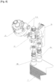
- the heat exchanger comprises, at its cold part formed by the inlet 9A of the secondary circuit 9 and the outlet 8B of the primary circuit 8 arranged side by side on one face of the heat exchanger, a part 27 for connecting said inlet and outlet respectively to the conduit 18 and to the return branch 11B.
- This connecting piece 27 which comprises two sections of conduit for said connections, forms the support for a drain valve 25 capable of allowing the tank to be drained via the return branch 11B.
- This connecting piece 27 also ensures the fixing of the heat exchanger 7 on the tank 2 and the fixing of the temperature probes.
- the heat exchanger 7 comprises, at its hot part formed by the inlet 8A of the primary circuit and the outlet 9B of the secondary circuit arranged side by side on the same face of the heat exchanger, a part 26 for connecting said inlet and outlet respectively to the forward branch 11A of the loop circuit and to the conduit 19.
- This connecting piece 26 which comprises two sections of conduit for said connections, also forms a means of connecting the pump 12. This connecting piece also supports some of the temperature probes.
- At least the heat exchanger, the pump 12 which is variable flow, the valve 31 and its displacement drive member 32 and the means 13 for regulating the flow of the pump 12 form a ready-to-assemble assembly.
- the heat exchanger To enable the heat exchanger to operate, it is necessary to heat the temperature of the tank to a temperature generally close to 70°C in the upper part of the tank, this temperature being able to be controlled using a temperature probe 28 positioned as close as possible to the heating system 6, for example in the housing body 23 presented below.
- the heating system 6 can take a large number of forms.
- the tank 2 comprises two electrical resistors, namely an upper electrical resistor and a lower electrical resistor, housed inside the tank, and a control unit for said electrical resistors.
- the control unit is configured to selectively control said electrical resistors. This control unit is also configured to control the electrical resistors at different temperature setpoints.
- This control unit can be made common with the pump control unit 17 and is formed in the same way as that described for the pump control unit of an electronic and computer system which comprises, for example, a microprocessor and a working memory.
- the set temperature of the lower electrical resistance is less than or equal to the set temperature of the upper electrical resistance.
- the upper electrical resistance takes priority.
- the tank 2 comprises, at the level of each of the electrical resistors, two orifices 21, 22 opposite each other, one 21, in the enclosure 51, the other 22, in the casing 52, these orifices 21, 22 being connected by a housing body 23 with a pierced bottom 231 forming a sheath for connecting said orifices 21, 22 together.
- the drilling of the bottom of the housing is bordered externally by a rim to form a tubular projection inserted into the orifice of the enclosure.
- the tubular projection of the housing body inserted into the orifice of the enclosure comprises two glove fingers open towards the inside of the housing body, each glove finger being made in one piece with the housing body.
- a temperature probe can be positioned inside one of the glove fingers and a cut-off thermostat can be positioned inside the other of the glove fingers.
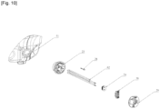
- Each electrical resistor 61, 62 is in the form of an elongated body provided with a seal 24 threaded onto the body of the resistor. This electrical resistor 61 or 62 is slidably inserted inside the housing body 23, passes through the bore 2311 of the bottom 231 of the housing body 23 to extend at least partially inside the tank 2.
- this electrical resistor 61 or 62 is positionable inside the housing body coaxially with the bore 2311 of the bottom of the housing body to protrude via said bore inside the enclosure, and is slidably movable inside the housing body.
- the seal 24 in sealed bearing contact with the resistor 61 or 62 seals the bore 2311 of the bottom 231 of the housing body 23.
- a part 30 can also be threaded onto the body of the resistor to cover the seal 24. This part 30 is fixed by screwing the housing body to prevent any untimely exit of the seal 24.
- This fixing part can therefore be threaded onto the electrical resistor after the seal and can be coupled by screwing to the housing body, this housing body comprising at least one screw well made in one piece with said body.
- the housing body 23 is closed by a cover 29 hiding the resistance which can be removed from the tank by simply pulling on the resistance. electric.
- This cover is housed in a reinforcement of the casing provided at the level of the casing orifice.
- the housing body comprises a bottom and a peripheral side wall and that the peripheral side wall of the housing body is provided with an external peripheral collar arranged to bear on the part of the internal surface of the casing surrounding the orifice of the casing.
- the tank may include only an electrical resistor.
- Each resistor is a hairpin electrical resistor comprising a tubular body inside which is housed a resistive wire and at least one thermofusible, the ends of the hairpin made in the form of two parallel branches each being provided with an electrical connector onto which the seal is capable of being threaded.
- the heating means may comprise a heat pump and a loop circulation circuit between the contents of the tank and the heat pump.
- the heating system may further comprise, in addition or as a variant, a solar collector 63 and means 64 for circulating the contents of the tank through said solar collector 63 as shown in figure 4
- the heating system may also include a boiler, for example gas, connected to the tank.
- the tank 2 is equipped, in its upper third, with an orifice 33 for filling the tank 2 with liquid.
- This filling orifice 33 is connected by a closable fluid connection 35 to the portion of the secondary circuit 9 extending between the inlet 9A of the secondary circuit 9 and the zone 10 for exchanging calories between the primary 8 and secondary 9 circuits of the heat exchanger 2.
- This closable fluid connection 35 is provided at the filling orifice 33 with a part 34 for connection to the tank 2.
- This connection part 34 is provided with a vent 36, an overflow orifice 37 and an additional orifice 38 acting as an overflow or vent depending on the filling level of the tank 2.
- the additional orifice 38 is arranged at a higher level than the overflow orifice 37.
- This additional orifice 38 is also arranged at a lower level than that occupied by the vent 36.
- the configuration of this connection part makes it possible to prevent any rise of “dead” water from the tank 2 into the filling liquid distribution network during the tank filling operation.
- This part 34 for connection to the tank 2 is also equipped with a closure member 43.
- This closure member 43 is, in the example shown, a pivoting valve pivotally mounted about a so-called horizontal axis extending perpendicular to the longitudinal axis of the connection part 34 which is a tubular part.
- This closure member 43 is shaped and sized to be returned to the closed position under the effect of its own weight.
- This normally closed closure member 43 is therefore able to move from the closed position to the open position under the effect, for example, of a filling of the tank.
- the presence of such a closure member makes it possible to limit the appearance of condensation at the cover 54 of the casing, in particular at the part of the cover 54 shown at 44 in the figures which at least partially overlaps the connection part 34.
- the tank 2 is equipped with a so-called lower level sensor 39 and a so-called upper level sensor 40 arranged at different heights in the tank 2.
- these sensors are floats offset axially along a rod inside the tank 2.
- the closable fluid connection 35 is provided with a closing member 41, such as a solenoid valve.
- This closing member 41 is equipped with an electrical control circuit 42.
- the electrical control circuit 42 is configured to switch from the closed state corresponding to the open position of the shutter member 41 to the open state corresponding to the closed position of the shutter member 41 at least in the activated state of the upper level sensor 40.
- the upper level sensor 40 acts as a switch for the electrical control circuit 42 of the shutter member 41 and switches the latter to open it.
- the latter acts as a switch for the electrical control circuit 42 of the shutter member 41 and switches the latter to open it.
- the device works as follows: When a draw-off is detected, this detection being carried out using the flow meter, temperature data measured by the various temperature probes arranged at the inlet and/or outlet of the primary and secondary circuits as well as the measured flow rate value are sent to the control unit 17 which opens the valve 31 and regulates the flow rate of the pump 12 according to said data to allow heating of the domestic cold water to the predetermined set temperature.
- the pump 12 is stopped and the heat exchanger 7 is drained by thermosiphon to prevent any stagnation of hot water inside the heat exchanger.
- the valve 31 is closed to prevent any continued circulation of fluid. Indeed, apart from a draw of domestic hot water, the pump is stopped.
- the pump is stopped.
- the cold water contained in the bottom of the tank pushes back the warm water from the exchanger which rises into the tank via the forward branch of the circuit 11 in a loop between the tank and the heat exchanger until the level of separation between cold water and hot water at the level of the cold water in the tank and in the water pipe of the forward branch of the loop circuit is the same.
- the warm water from the exchanger is replaced by cold water from the bottom of the tank by a thermosiphon phenomenon.
- This reverse circulation is represented in the figure 2 . This reverse circulation is prevented once valve 31 is closed, this closing of valve 31 occurring a few minutes after stopping pump 12, once the cooling of the heat exchanger is complete.
Landscapes
- Engineering & Computer Science (AREA)
- Physics & Mathematics (AREA)
- General Engineering & Computer Science (AREA)
- Chemical & Material Sciences (AREA)
- Combustion & Propulsion (AREA)
- Mechanical Engineering (AREA)
- Thermal Sciences (AREA)
- Fluid Mechanics (AREA)
- Measurement Of Levels Of Liquids Or Fluent Solid Materials (AREA)
- Steam Or Hot-Water Central Heating Systems (AREA)
- Heat-Pump Type And Storage Water Heaters (AREA)
- Pressure Vessels And Lids Thereof (AREA)
- Instantaneous Water Boilers, Portable Hot-Water Supply Apparatuses, And Control Of Portable Hot-Water Supply Apparatuses (AREA)
Claims (14)
- Vorrichtung (1) zur Erzeugung von warmem Fluid, insbesondere von Warmwasser, umfassend:- einen Behälter (2) zum Aufnehmen von Flüssigkeit, der mit mindestens einem Fluideinlass (3) und einem Fluidauslass (4) ausgestattet ist, wobei mindestens der sogenannte innere Teil des Behälters (2), der geeignet ist, um mit der Einfüllflüssigkeit des Behälters (2) in Kontakt zu sein, aus einem synthetischen Material ist,- ein System (6) zum Erhitzen des Inhalts des Behälters (2),- einen Wärmetauscher (7), umfassend einen Primärkreislauf (8), der mit mindestens einem Fluideinlass (8A) und einem Fluidauslass (8B) ausgestattet ist, einen Sekundärkreislauf (9), der mit mindestens einem Fluideinlass (9A) und einem Fluidauslass (9B) ausgestattet ist, und einen Austauschbereich (10) von Kalorien zwischen dem Primärkreislauf (8) und dem Sekundärkreislauf (9), die außerhalb des Behälters (2) angeordnet ist,- einen geschlossenen Umwälzkreislauf (11) zwischen dem Behälter (2) und dem Primärkreislauf (8) des Wärmetauschers (7), und- eine Pumpe (12), die in dem geschlossenen Umwälzkreislauf (11) angeordnet ist, wobei der Einlass (9A) des Sekundärkreislaufs (9) des Wärmetauschers (7) an mindestens eine Quelle des zu erwärmenden Fluids anschließbar ist, um die Erzeugung von warmem Fluid an dem Auslass des Sekundärkreislaufs (9) zu ermöglichen,- ein Ventil (31), das in dem geschlossenen Umwälzkreislauf (11) zwischen dem Behälter (2) und dem Primärkreislauf (8) des Wärmetauschers (7) angeordnet ist,- ein Element (32) zum Antreiben einer Verstellung des Ventils (31) zwischen einer offenen Stellung und einer geschlossenen Stellung,- eine Steuereinheit (17) zumindest der Pumpe (12) und des Elements (32) zum Antreiben einer Verstellung des Ventils (31), wobei die Steuereinheit (17) konfiguriert ist, um die Betätigung des Elements (32) zum Antreiben einer Verstellung des Ventils (31) und folglich den Übergang des Ventils (31) von der offenen Stellung in die geschlossene Stellung oder umgekehrt abhängig von dem Ein/Aus-Zustand der Pumpe (12) zu steuern, dadurch gekennzeichnet, dass der Behälter (2) in der unteren Hälfte des Behälters (2) an der Außenfläche des Behälters (2) eine Aussparung (16) umfasst, in deren Innern der Wärmetauscher (7), der ein Gegenstrom-, vorzugsweise Plattenwärmetauscher (7) ist, geeignet ist, untergebracht zu werden, um sich zumindest teilweise innerhalb der Gesamtabmessung des Behälters (2) zu erstrecken.
- Vorrichtung (1) nach Anspruch 1, dadurch gekennzeichnet, dass die Vorrichtung (1) eine Uhr (171) umfasst und dass die Steuereinheit (17) konfiguriert ist, um die Betätigung des Elements (32) zum Antreiben einer Verstellung des Ventils (31) in Richtung einer Öffnung des Ventils (31) parallel zu der Steuerung des Starts der Pumpe (12) zu steuern, und konfiguriert ist, um die Betätigung des Elements (32) zum Antreiben einer Verstellung des Ventils (31) in Richtung eines Schließens des Ventils (31) in dem angehaltenen Zustand der Pumpe (12) nach Stillstand der Pumpe (12) über eine vorbestimmte Zeitdauer zu steuern.
- Vorrichtung (1) nach einem der Ansprüche 1 oder 2, dadurch gekennzeichnet, dass die Pumpe (12) eine Pumpe mit variabler Fördermenge ist und dass die Vorrichtung (1) Einrichtungen (13) zur Regulierung der Fördermenge der Pumpe (12) umfasst, diese Einrichtungen (13) zur Regulierung der Fördermenge der Pumpe (12) umfassend einen Durchflussmesser (14), der vorzugsweise an dem Einlass des Sekundärkreislaufs (9) angeordnet ist, und mindestens zwei Temperaturfühler (131, 132), wovon mindestens einer in dem geschlossenen Umwälzkreislauf (11) zwischen dem Behälter (2) und dem Primärkreislauf (8) des Wärmetauschers (7) angeordnet ist, und dass die Steuereinheit (17) konfiguriert ist, um die Pumpe (12) mindestens abhängig von Daten zu steuern, die von den Temperaturfühlern (131, 132) und dem Durchflussmesser (14) bereitgestellt werden.
- Vorrichtung (1) nach Anspruch 3, dadurch gekennzeichnet, dass die Vorrichtung (1) an dem Einlass des Sekundärkreislaufs (9) in dem Anschlussbereich des Einlasses (9A) des Sekundärkreislaufs (9) an mindestens einer Quelle für zu erwärmendes Fluid eine Leitung (18) umfasst, die mindestens teilweise in der Stärke des Behälters (2) angeordnet ist, wobei diese sogenannte Einlassleitung (18) an einem Ende mit dem Einlass (9A) des Sekundärkreislaufs (9) des Wärmetauschers (2) koppelbar ist und sich an dem gegenüberliegenden Ende des Anschlusses an mindestens eine Quelle für zu erwärmendes Fluids in zwei Zweige (18A, 18B) teilt, wovon der eine (18A) mit einem Verschlusselement (20) und der andere (18B) mit dem Durchflussmesser (14) ausgestattet ist.
- Vorrichtung (1) nach einem der Ansprüche 1 bis 4, dadurch gekennzeichnet, dass der geschlossene Umwälzkreislauf (11) zwischen dem Behälter (2) und dem Primärkreislauf (8) des Wärmetauschers (7) einen Vorlaufzweig (11A), der zwischen dem Auslass (4) des Behälters (2) und dem Einlass (8A) des Primärkreislaufs (8) angeordnet ist, und einen Rücklaufzweig (11B), der zwischen dem Auslass (8B) des Primärkreislaufs (8) und dem Einlass (3) des Behälters (2) angeordnet ist, umfasst, wobei die Pumpe (12) und das Ventil (31) vorzugsweise in dem Vorlaufzweig (11A) des geschlossenen Umwälzkreislaufs (11) angeordnet sind.
- Vorrichtung (1) nach einem der Ansprüche 1 bis 5, dadurch gekennzeichnet, dass der Behälter (2) mit einer Öffnung (33) zum Befüllen des Behälters (2) mit Flüssigkeit ausgestattet ist, wobei diese Einfüllöffnung (33) über eine verschließbare fluidische Verbindung (35) an dem Abschnitt des Sekundärkreislaufs (9) angeschlossen ist, der sich zwischen dem Einlass (9A) des Sekundärkreislaufs (9) und Austauschbereich (10) von Kalorien zwischen dem Primärkreislauf (8) und dem Sekundärkreislauf (9) des Wärmetauschers (2) erstreckt.
- Vorrichtung (1) nach Anspruch 6, dadurch gekennzeichnet, dass die verschließbare fluidische Verbindung (35) auf Höhe der Einfüllöffnung (33) mit einem Anschlussstück (34) an dem Behälter (2) versehen ist, wobei dieses Anschlussstück (34) mit einer Entlüftung (36), einer Überlauföffnung (37) und einer zusätzlichen Öffnung (38) versehen ist, die je nach Füllstand des Behälters (2) als Überlauf oder als Entlüftung dient.
- Vorrichtung (1) nach einem der Ansprüche 6 oder 7, dadurch gekennzeichnet, dass der Behälter (2) mit einem Sensor für den sogenannten unteren Füllstand (39) und einem Sensor für den sogenannten oberen Füllstand (40) ausgestattet ist, die auf unterschiedlichen Höhen in dem Behälter (2) angeordnet sind, dass die verschließbare fluidische Verbindung (35) mit einem Verschlusselement (41) versehen ist, das mit einer elektrischen Steuerschaltung (42) ausgestattet ist, und dass die elektrische Steuerschaltung (42) konfiguriert ist, um von dem geschlossenen Zustand, der der offenen Stellung des Verschlusselements (41) entspricht, in den offenen Zustand überzugehen, der der geschlossenen Stellung des Verschlusselements (41) mindestens in dem aktivierten Zustand des oberen Füllstandsensors (40) entspricht.
- Vorrichtung (1) nach einem der Ansprüche 1 bis 8, dadurch gekennzeichnet, dass der Auslass (4) des Behälters (2), der an dem Einlass (8A) des Primärkreislaufs (8) anschließbar ist, in dem oberen Drittel des Innenvolumens des Behälters (2) angeordnet ist, und der Einlass des Behälters (2), der an dem Auslass (8A) des Primärkreislaufs (8) anschließbar ist, in dem unteren Drittel des Innenvolumens des Behälters (2) angeordnet ist, dass mindestens ein Teil des Heizsystems (6) in dem Behälter (2) untergebracht ist und dass der Einlass (3) des Behälters (2), der an dem Auslass (8B) des Primärkreislaufs (8) des Wärmetauschers (2) anschließbar ist, auf einer Höhe in den Behälter (2) mündet, die niedriger ist als die Höhe, die von dem Teil des Heizsystems (6) eingenommen wird, der in dem Behälter (2) untergebracht ist.
- Vorrichtung (1) nach einem der Ansprüche 1 bis 9, dadurch gekennzeichnet, dass der Wärmetauscher (7) in dem an dem Behälter (2) angeschlossenen Zustand auf einer Höhe angeordnet ist, die niedriger ist als die Höhe, die von dem Einlass des Behälters (2) eingenommen wird, der an dem Auslass (8B) des Primärkreislaufs (8) des Wärmetauschers (7) anschließbar ist.
- Vorrichtung (1) nach einem der Ansprüche 1 bis 10, dadurch gekennzeichnet, dass der Behälter (2) ein Gehäuse (51), eine Hülle (52), die das Gehäuse (51) mindestens teilweise umgibt, und einen Isolator (53), der zwischen dem Gehäuse (51) und der Hülle (52) angeordnet ist, umfasst.
- Vorrichtung (1) nach Anspruch 11, dadurch gekennzeichnet, dass mindestens ein Teil des Heizsystems (6) in dem Behälter (2) untergebracht ist und dass die Stärke des Behälters (2), genommen zwischen der Außenseite der Hülle (52) und der Innenseite des Gehäuses (51), in dem Teil des Behälters (2), der sich über den Teil des Heizsystems (6) erstreckt, der im Inneren des Behälters (2) untergebracht ist, zumindest stellenweise größer ist als die Stärke des Behälters, der sich unter dem Teil des Heizsystems (6) erstreckt, der im Inneren des Behälters (2) untergebracht ist.
- Vorrichtung (1) nach einem der Ansprüche 1 bis 12, dadurch gekennzeichnet, dass mindestens der Wärmetauscher (7), die Pumpe (12), die eine variable Fördermenge aufweist, und das Ventil (31) mit seinem Element (32) zum Antreiben einer Verstellung, das vorzugsweise ein Motor ist, eine einbaufertige Einheit bilden.
- Vorrichtung (1) nach einem der Ansprüche 1 bis 13 in Kombination mit einem der Ansprüche 11 oder 12, dadurch gekennzeichnet, dass das Heizsystem (6) mindestens einen elektrischen Widerstand (61, 62) umfasst, der im Inneren des Behälters (2) untergebracht ist, dass der Behälter (2) auf Höhe des oder mindestens eines der elektrischen Widerstände (61, 62) zwei einander gegenüberliegende Öffnungen (21, 22) umfasst, wovon eine (21) in dem Gehäuse (51) und die andere (22) in dem Mantel (52) ausgebildet ist, wobei diese Öffnungen (21, 22) durch einen Gehäusekörper (23) mit durchbohrtem Boden (231) verbunden sind, der eine Hülse zur Verbindung der Öffnungen (21, 22) untereinander bildet, wobei sich dieser Gehäusekörper (23) mindestens teilweise in das Innere des Gehäuses (51) erstreckt, und dass der elektrische Widerstand (61, 62) in Form eines länglichen Körpers vorliegt, der mit einer Dichtung (24) versehen ist, die auf den elektrischen Widerstand (61, 62) aufgeschoben ist, wobei diese Dichtung (24) in dichtem Anlagekontakt mit dem elektrischen Widerstand (61, 62) die Bohrung (2311) des Bodens (231) des Gehäusekörpers (23) in dem Zustand, in dem der elektrische Widerstand (61, 62) durch die Bohrung (2311) hindurchgeführt wird, dicht verschließt.
Applications Claiming Priority (3)
| Application Number | Priority Date | Filing Date | Title |
|---|---|---|---|
| FR1913518A FR3103885B1 (fr) | 2019-11-29 | 2019-11-29 | Réservoir de liquide apte à être chauffé |
| FR1913514A FR3103886B1 (fr) | 2019-11-29 | 2019-11-29 | Dispositif de production de fluide chaud |
| PCT/FR2020/052168 WO2021105610A1 (fr) | 2019-11-29 | 2020-11-25 | Dispositif de production de fluide chaud |
Publications (3)
| Publication Number | Publication Date |
|---|---|
| EP4065901A1 EP4065901A1 (de) | 2022-10-05 |
| EP4065901C0 EP4065901C0 (de) | 2025-01-01 |
| EP4065901B1 true EP4065901B1 (de) | 2025-01-01 |
Family
ID=73740431
Family Applications (2)
| Application Number | Title | Priority Date | Filing Date |
|---|---|---|---|
| EP20820512.0A Active EP4065901B1 (de) | 2019-11-29 | 2020-11-25 | Vorrichtung zum produzieren von heisser flüssigkeit |
| EP20820513.8A Active EP4065907B1 (de) | 2019-11-29 | 2020-11-25 | Beheizbarer flüssigkeitstank |
Family Applications After (1)
| Application Number | Title | Priority Date | Filing Date |
|---|---|---|---|
| EP20820513.8A Active EP4065907B1 (de) | 2019-11-29 | 2020-11-25 | Beheizbarer flüssigkeitstank |
Country Status (6)
| Country | Link |
|---|---|
| US (2) | US12504202B2 (de) |
| EP (2) | EP4065901B1 (de) |
| CA (2) | CA3158093A1 (de) |
| ES (2) | ES3015546T3 (de) |
| PL (2) | PL4065907T3 (de) |
| WO (2) | WO2021105611A1 (de) |
Families Citing this family (2)
| Publication number | Priority date | Publication date | Assignee | Title |
|---|---|---|---|---|
| UA122651C2 (uk) * | 2020-02-13 | 2020-12-10 | Костянтин Леонідович Серебреников | Двоконтурний електричний котел (варіанти) |
| SE547063C2 (en) * | 2020-04-30 | 2025-04-15 | Braathen Thor F | A water heater |
Family Cites Families (52)
| Publication number | Priority date | Publication date | Assignee | Title |
|---|---|---|---|---|
| US1717207A (en) * | 1927-12-28 | 1929-06-11 | Edison Electric Appliance Co | Electric water heater |
| US1799951A (en) * | 1929-02-28 | 1931-04-07 | Clarence K Bros | Hot-water heater |
| US2058769A (en) * | 1933-12-05 | 1936-10-27 | F C Colby | Heating apparatus and method of heating |
| US2618731A (en) * | 1951-06-29 | 1952-11-18 | Gen Motors Corp | Electrical heating unit |
| US3116402A (en) * | 1960-08-11 | 1963-12-31 | Wiegand Co Edwin L | Electric heaters |
| US3306109A (en) * | 1963-07-11 | 1967-02-28 | Robertshaw Controls Co | Insulator insert for thermal sensing device |
| US3253731A (en) * | 1963-12-23 | 1966-05-31 | Gen Electric | Hot water storage tanks |
| AU417804B2 (en) | 1967-07-26 | 1971-10-13 | Rheem Australia Pty. Limited | Improvements in water heaters |
| AT278985B (de) | 1968-04-04 | 1970-02-25 | Austria Email Ag | Elektro-Heißwasserspeicher |
| US3546431A (en) * | 1969-04-25 | 1970-12-08 | Erich L Gibbs | Immersion heater and method of making the same |
| US3621566A (en) * | 1969-05-07 | 1971-11-23 | Standard Motor Products | Method of making an electrical heating element |
| US3772498A (en) * | 1973-05-03 | 1973-11-13 | Emerson Electric Co | Electric heating assembly |
| US3997760A (en) * | 1974-12-06 | 1976-12-14 | Electro-Therm, Inc. | Electric heating element with bulkhead mounting means |
| US4152578A (en) * | 1977-10-03 | 1979-05-01 | Emerson Electric Co. | Electric heating elements |
| US4543469A (en) * | 1982-04-26 | 1985-09-24 | Emerson Electric Co. | Grounding arrangement for metal sheathed heating element having a plastic mounting member |
| US4543468A (en) * | 1982-12-16 | 1985-09-24 | Borg-Warner Corporation | Control system for water heater with external heat source |
| US4498622A (en) * | 1983-05-23 | 1985-02-12 | Borg-Warner Corporation | Quick recovery heat pump water heater |
| US4540874A (en) * | 1984-01-13 | 1985-09-10 | Borg-Warner Corporation | Control system for electric water heater with heat pump external heat source |
| US4684786A (en) * | 1984-08-01 | 1987-08-04 | Navistar International Corporation | Electrically heated fuel pick-up assembly for vehicle fuel tanks |
| DE8428132U1 (de) | 1984-09-25 | 1986-01-23 | Wilhelm & Sander GmbH, 3418 Uslar | Wasserspeicher, insbesondere Warmwasserspeicher |
| US4765507A (en) * | 1986-01-24 | 1988-08-23 | Ecodyne Corporation | Pressure vessel with an improved sidewall structure |
| US5020721A (en) * | 1989-09-19 | 1991-06-04 | Gas Fired Products | Rapid recovery gas hot water heater |
| DE4035115C2 (de) * | 1990-03-12 | 1993-11-04 | Sandler Energietechnik | Anordnung zum aufheizen und zum bereitstellen von warmem oder heissem brauchwasser von trinkwasserqualitaet |
| US5255338A (en) * | 1991-07-12 | 1993-10-19 | Electric Power Research Institute, Inc. | Heat pump water heater control circuit |
| US5220638A (en) * | 1991-09-30 | 1993-06-15 | Mor-Flo Industries, Inc. | Water heater with an improved thermostat mounting and a method of making such water heaters |
| DE4206074C2 (de) * | 1992-02-27 | 1998-07-16 | Sandler Energietechnik | Vorrichtung zur Regelung der Entnahmetemperatur von Brauchwasser mit Trinkwasserqualität |
| US5371831A (en) * | 1992-10-07 | 1994-12-06 | Water Heater Innovation, Inc. | Electrical heating element assembly for water heater |
| CA2087380C (en) * | 1993-01-15 | 1996-10-15 | Claude Lesage | Replaceable adaptor for a hot water tank resistive heating element |
| US5335311A (en) * | 1993-01-19 | 1994-08-02 | Glengarry Industries Ltd. | Modular galvanic current control resistor assembly for mounting on an electric immersion heater |
| US5404421A (en) * | 1993-01-27 | 1995-04-04 | Emerson Electric Co. | Fuel heating element mounting plug housing a thermostat |
| US5293844A (en) * | 1993-06-04 | 1994-03-15 | Aos Holding Company | Protective shield for the electrical components of a water heater |
| US5367602A (en) * | 1993-10-21 | 1994-11-22 | Lennox Industries Inc. | Control apparatus and method for electric heater with external heat source |
| US5506931A (en) * | 1994-03-09 | 1996-04-09 | The Commonwealth Of Puerto Rico | Immersion type water heating element assembly with permanently wired electrical supply |
| US5921207A (en) * | 1997-05-06 | 1999-07-13 | Disalvo; Joseph | Automatic flushing system for water tank |
| US6256456B1 (en) * | 1998-02-19 | 2001-07-03 | Emerson Electric Co. | Hot water dispenser with heat dissipation plates for dry-start protection |
| KR200172037Y1 (ko) * | 1999-09-15 | 2000-03-15 | 천열에너지주식회사 | 전열선이 삽입된 온수관의 단부의 밀폐장치 |
| DE19958491C1 (de) * | 1999-12-04 | 2001-05-10 | Protechna Sa | Transport- und Lagerbehälter für Flüssigkeiten |
| US7040108B1 (en) * | 2003-12-16 | 2006-05-09 | Flammang Kevin E | Ambient thermal energy recovery system |
| JP2005195246A (ja) * | 2004-01-07 | 2005-07-21 | Rinnai Corp | 給湯器 |
| US20060029375A1 (en) * | 2004-08-05 | 2006-02-09 | Bradenbaugh Ken A | Water heater and method of mounting a heating element in a water heater |
| EP1731850B2 (de) * | 2005-06-10 | 2016-08-17 | Bleckmann GmbH & Co. KG | Flanschloser Kunststoff-Boiler |
| US7509033B2 (en) * | 2006-12-15 | 2009-03-24 | Rheem Manufacturing Company | Side port insert design for water heater |
| WO2009077966A2 (en) | 2007-12-14 | 2009-06-25 | Activehome Ltd. | Heater tank |
| US8478116B2 (en) * | 2009-08-18 | 2013-07-02 | Chromalox, Inc. | Immersion heater with exhaust path for overpressure |
| US8991638B2 (en) * | 2011-08-17 | 2015-03-31 | General Electric Company | Water seepage abatement in water heaters |
| WO2014116943A2 (en) * | 2013-01-25 | 2014-07-31 | Spx Corporation | Companion water heater |
| US9063551B2 (en) * | 2013-02-14 | 2015-06-23 | Intellihot Green Technologies, Inc. | Adaptive heating control system for a water heater |
| JP6766356B2 (ja) * | 2014-08-25 | 2020-10-14 | 横浜ゴム株式会社 | 流体タンクの配管用ノズル部の構造 |
| DE102016206906A1 (de) * | 2016-04-22 | 2017-10-26 | Areva Gmbh | Passives Füllstandsregelsystem |
| BE1024914B1 (nl) * | 2017-01-16 | 2018-08-16 | Minnoy Bvba | Een verwarmingssysteem en een verwarmingswerkwijze |
| JP7524485B2 (ja) * | 2021-02-07 | 2024-07-29 | オクトパス エナジー ヒーティング リミテッド | エネルギーと水との使用の低減をサポートする方法とシステムと装置 |
| GB2612495B (en) * | 2021-02-07 | 2023-12-20 | Octopus Energy Heating Ltd | Methods and systems and apparatus to support reduced energy and water usage |
-
2020
- 2020-11-25 EP EP20820512.0A patent/EP4065901B1/de active Active
- 2020-11-25 US US17/779,353 patent/US12504202B2/en active Active
- 2020-11-25 US US17/779,365 patent/US20230066658A1/en active Pending
- 2020-11-25 EP EP20820513.8A patent/EP4065907B1/de active Active
- 2020-11-25 CA CA3158093A patent/CA3158093A1/fr active Pending
- 2020-11-25 CA CA3158097A patent/CA3158097A1/fr active Pending
- 2020-11-25 WO PCT/FR2020/052169 patent/WO2021105611A1/fr not_active Ceased
- 2020-11-25 PL PL20820513.8T patent/PL4065907T3/pl unknown
- 2020-11-25 ES ES20820512T patent/ES3015546T3/es active Active
- 2020-11-25 ES ES20820513T patent/ES2989270T3/es active Active
- 2020-11-25 WO PCT/FR2020/052168 patent/WO2021105610A1/fr not_active Ceased
- 2020-11-25 PL PL20820512.0T patent/PL4065901T3/pl unknown
Also Published As
| Publication number | Publication date |
|---|---|
| CA3158093A1 (fr) | 2021-06-03 |
| PL4065907T3 (pl) | 2024-09-30 |
| US20230066658A1 (en) | 2023-03-02 |
| US20220404065A1 (en) | 2022-12-22 |
| EP4065901C0 (de) | 2025-01-01 |
| US12504202B2 (en) | 2025-12-23 |
| WO2021105611A1 (fr) | 2021-06-03 |
| ES2989270T3 (es) | 2024-11-25 |
| EP4065907B1 (de) | 2024-05-15 |
| EP4065907A1 (de) | 2022-10-05 |
| PL4065901T3 (pl) | 2025-06-16 |
| ES3015546T3 (en) | 2025-05-06 |
| WO2021105610A1 (fr) | 2021-06-03 |
| CA3158097A1 (fr) | 2021-06-03 |
| EP4065907C0 (de) | 2024-05-15 |
| EP4065901A1 (de) | 2022-10-05 |
Similar Documents
| Publication | Publication Date | Title |
|---|---|---|
| EP4065901A1 (de) | Vorrichtung zum produzieren von heisser flüssigkeit | |
| EP0116005A1 (de) | Vorrichtung für Frostschutz von Wasserzählern und Wasserhähnen | |
| EP2247897A1 (de) | Anlage zur produktion von haushalts-warmwasser | |
| FR2488422A1 (fr) | Procede et dispositif pour obtenir de l'eau chaude a une temperature predeterminee a partir d'un reservoir a une temperature non uniforme et variable | |
| FR3103886A1 (fr) | Dispositif de production de fluide chaud | |
| WO2008053089A1 (fr) | Vanne thermostatique multivoies pour la distribution selective et la regulation de debit d'un liquide de refroidissement dans un circuit de refroidissement d'un moteur de vehicule automobile | |
| FR2733822A1 (fr) | Module de distribution pour installation de chauffage central avec plancher chauffant et radiateurs | |
| WO2000050832A1 (fr) | Echangeur thermique a plaques, a vanne integree | |
| EP2434187B1 (de) | Steuerverfahren eines Thermostatventils | |
| FR2727195A1 (fr) | Module de distribution pour installation de chauffage central avec plancher chauffant et radiateurs | |
| EP0085590A1 (de) | Fluidansaugvorrichtung, angeordnet in einem Tank, speziell für flüssige Brennstoffe | |
| EP3163208A1 (de) | Heizsystem und vorrichtung zur warmwassererzeugung im sanitärbereich und zum heizen, die dieses heizsystem umfasst | |
| EP2014921A1 (de) | System zum Sparen des abfließenden Wassers, während man auf das heiße Wasser wartet, in Heißwasserverteilungsanlagen | |
| FR2553181A1 (fr) | Dispositif permettant le stockage thermique a partir de deux sources energetiques, et installation utilisant un tel dispositif | |
| EP3178573B1 (de) | Reinigungsanlage, transformationsverfahren und reinigungsverfahren, bei dem diese reinigungsanlage zum einsatz kommt | |
| EP3026385B1 (de) | Konfigurierbares rohr zum einspritzen oder auslassen einer flüssigkeit in einem behälter | |
| FR2587790A1 (fr) | Dispositif modulaire permettant le stockage thermique a partir d'au moins deux sources energetiques, dont l'une est intermittente, et installation utilisant un tel dispositif | |
| CA3137466C (fr) | Dispositif de nettoyage d'un objet. | |
| FR3150849A1 (fr) | Chauffe-eau thermodynamique et procédé de chauffage d’eau le mettant en œuvre | |
| FR3103884A1 (fr) | Cuve de stockage compacte et ensemble chauffe-eau sanitaire | |
| FR2506908A1 (fr) | Chaudiere electrique | |
| FR3009018B1 (fr) | Circuit de refroidissement d'un moteur thermique de vehicule automobile et procede de gestion associe | |
| FR3054875B1 (fr) | Installation de production d'eau chaude sanitaire et procede de pilotage de cette installation | |
| FR2614678A1 (fr) | Perfectionnements aux installations de chauffage a accumulation, utilisant au moins une source d'energie intermittente | |
| EP2947393B1 (de) | Schutzumlauf gegen überhitzungseffekte in einem heisswasserbereitungssystem, und entsprechendes heisswasserbereitungssystem |
Legal Events
| Date | Code | Title | Description |
|---|---|---|---|
| STAA | Information on the status of an ep patent application or granted ep patent |
Free format text: STATUS: UNKNOWN |
|
| STAA | Information on the status of an ep patent application or granted ep patent |
Free format text: STATUS: THE INTERNATIONAL PUBLICATION HAS BEEN MADE |
|
| PUAI | Public reference made under article 153(3) epc to a published international application that has entered the european phase |
Free format text: ORIGINAL CODE: 0009012 |
|
| STAA | Information on the status of an ep patent application or granted ep patent |
Free format text: STATUS: REQUEST FOR EXAMINATION WAS MADE |
|
| 17P | Request for examination filed |
Effective date: 20220510 |
|
| AK | Designated contracting states |
Kind code of ref document: A1 Designated state(s): AL AT BE BG CH CY CZ DE DK EE ES FI FR GB GR HR HU IE IS IT LI LT LU LV MC MK MT NL NO PL PT RO RS SE SI SK SM TR |
|
| DAV | Request for validation of the european patent (deleted) | ||
| DAX | Request for extension of the european patent (deleted) | ||
| P01 | Opt-out of the competence of the unified patent court (upc) registered |
Effective date: 20230530 |
|
| REG | Reference to a national code |
Ref country code: DE Ref legal event code: R079 Free format text: PREVIOUS MAIN CLASS: F24D0017000000 Ipc: F24H0009181800 Ref document number: 602020044197 Country of ref document: DE |
|
| GRAP | Despatch of communication of intention to grant a patent |
Free format text: ORIGINAL CODE: EPIDOSNIGR1 |
|
| STAA | Information on the status of an ep patent application or granted ep patent |
Free format text: STATUS: GRANT OF PATENT IS INTENDED |
|
| RIC1 | Information provided on ipc code assigned before grant |
Ipc: F24H 15/34 20220101ALI20240620BHEP Ipc: F24H 15/335 20220101ALI20240620BHEP Ipc: F24H 15/238 20220101ALI20240620BHEP Ipc: F24H 15/212 20220101ALI20240620BHEP Ipc: F24H 9/20 20220101ALI20240620BHEP Ipc: F24H 15/31 20220101ALI20240620BHEP Ipc: F24H 1/20 20220101ALI20240620BHEP Ipc: F24H 1/18 20220101ALI20240620BHEP Ipc: F24H 9/1818 20220101AFI20240620BHEP |
|
| INTG | Intention to grant announced |
Effective date: 20240710 |
|
| GRAS | Grant fee paid |
Free format text: ORIGINAL CODE: EPIDOSNIGR3 |
|
| GRAA | (expected) grant |
Free format text: ORIGINAL CODE: 0009210 |
|
| STAA | Information on the status of an ep patent application or granted ep patent |
Free format text: STATUS: THE PATENT HAS BEEN GRANTED |
|
| AK | Designated contracting states |
Kind code of ref document: B1 Designated state(s): AL AT BE BG CH CY CZ DE DK EE ES FI FR GB GR HR HU IE IS IT LI LT LU LV MC MK MT NL NO PL PT RO RS SE SI SK SM TR |
|
| REG | Reference to a national code |
Ref country code: GB Ref legal event code: FG4D Free format text: NOT ENGLISH |
|
| REG | Reference to a national code |
Ref country code: CH Ref legal event code: EP |
|
| REG | Reference to a national code |
Ref country code: DE Ref legal event code: R096 Ref document number: 602020044197 Country of ref document: DE |
|
| REG | Reference to a national code |
Ref country code: IE Ref legal event code: FG4D Free format text: LANGUAGE OF EP DOCUMENT: FRENCH |
|
| U01 | Request for unitary effect filed |
Effective date: 20250130 |
|
| P04 | Withdrawal of opt-out of the competence of the unified patent court (upc) registered |
Free format text: CASE NUMBER: APP_5775/2025 Effective date: 20250204 |
|
| U07 | Unitary effect registered |
Designated state(s): AT BE BG DE DK EE FI FR IT LT LU LV MT NL PT RO SE SI Effective date: 20250205 |
|
| REG | Reference to a national code |
Ref country code: ES Ref legal event code: FG2A Ref document number: 3015546 Country of ref document: ES Kind code of ref document: T3 Effective date: 20250506 |
|
| PG25 | Lapsed in a contracting state [announced via postgrant information from national office to epo] |
Ref country code: NO Free format text: LAPSE BECAUSE OF FAILURE TO SUBMIT A TRANSLATION OF THE DESCRIPTION OR TO PAY THE FEE WITHIN THE PRESCRIBED TIME-LIMIT Effective date: 20250401 Ref country code: IS Free format text: LAPSE BECAUSE OF FAILURE TO SUBMIT A TRANSLATION OF THE DESCRIPTION OR TO PAY THE FEE WITHIN THE PRESCRIBED TIME-LIMIT Effective date: 20250501 |
|
| PG25 | Lapsed in a contracting state [announced via postgrant information from national office to epo] |
Ref country code: HR Free format text: LAPSE BECAUSE OF FAILURE TO SUBMIT A TRANSLATION OF THE DESCRIPTION OR TO PAY THE FEE WITHIN THE PRESCRIBED TIME-LIMIT Effective date: 20250101 |
|
| PG25 | Lapsed in a contracting state [announced via postgrant information from national office to epo] |
Ref country code: GR Free format text: LAPSE BECAUSE OF FAILURE TO SUBMIT A TRANSLATION OF THE DESCRIPTION OR TO PAY THE FEE WITHIN THE PRESCRIBED TIME-LIMIT Effective date: 20250402 |
|
| PG25 | Lapsed in a contracting state [announced via postgrant information from national office to epo] |
Ref country code: CZ Free format text: LAPSE BECAUSE OF FAILURE TO SUBMIT A TRANSLATION OF THE DESCRIPTION OR TO PAY THE FEE WITHIN THE PRESCRIBED TIME-LIMIT Effective date: 20250101 |
|
| PG25 | Lapsed in a contracting state [announced via postgrant information from national office to epo] |
Ref country code: SM Free format text: LAPSE BECAUSE OF FAILURE TO SUBMIT A TRANSLATION OF THE DESCRIPTION OR TO PAY THE FEE WITHIN THE PRESCRIBED TIME-LIMIT Effective date: 20250101 |
|
| PG25 | Lapsed in a contracting state [announced via postgrant information from national office to epo] |
Ref country code: SK Free format text: LAPSE BECAUSE OF FAILURE TO SUBMIT A TRANSLATION OF THE DESCRIPTION OR TO PAY THE FEE WITHIN THE PRESCRIBED TIME-LIMIT Effective date: 20250101 |
|
| PLBE | No opposition filed within time limit |
Free format text: ORIGINAL CODE: 0009261 |
|
| STAA | Information on the status of an ep patent application or granted ep patent |
Free format text: STATUS: NO OPPOSITION FILED WITHIN TIME LIMIT |
|
| REG | Reference to a national code |
Ref country code: CH Ref legal event code: L10 Free format text: ST27 STATUS EVENT CODE: U-0-0-L10-L00 (AS PROVIDED BY THE NATIONAL OFFICE) Effective date: 20251112 |
|
| 26N | No opposition filed |
Effective date: 20251002 |
|
| REG | Reference to a national code |
Ref country code: CH Ref legal event code: U11 Free format text: ST27 STATUS EVENT CODE: U-0-0-U10-U11 (AS PROVIDED BY THE NATIONAL OFFICE) Effective date: 20251222 |
|
| U20 | Renewal fee for the european patent with unitary effect paid |
Year of fee payment: 6 Effective date: 20251127 |
|
| PGFP | Annual fee paid to national office [announced via postgrant information from national office to epo] |
Ref country code: GB Payment date: 20251128 Year of fee payment: 6 |
|
| PGFP | Annual fee paid to national office [announced via postgrant information from national office to epo] |
Ref country code: TR Payment date: 20251121 Year of fee payment: 6 |
|
| PGFP | Annual fee paid to national office [announced via postgrant information from national office to epo] |
Ref country code: CH Payment date: 20251222 Year of fee payment: 6 |
|
| PGFP | Annual fee paid to national office [announced via postgrant information from national office to epo] |
Ref country code: IE Payment date: 20251128 Year of fee payment: 6 |
|
| PGFP | Annual fee paid to national office [announced via postgrant information from national office to epo] |
Ref country code: PL Payment date: 20251125 Year of fee payment: 6 |
|
| PGFP | Annual fee paid to national office [announced via postgrant information from national office to epo] |
Ref country code: ES Payment date: 20251229 Year of fee payment: 6 |