EP4065938B1 - Vorrichtung zur überwachung der mechanischen integrität einer augensicherheitskomponente einer beleuchtungsvorrichtung - Google Patents
Vorrichtung zur überwachung der mechanischen integrität einer augensicherheitskomponente einer beleuchtungsvorrichtung Download PDFInfo
- Publication number
- EP4065938B1 EP4065938B1 EP20815969.9A EP20815969A EP4065938B1 EP 4065938 B1 EP4065938 B1 EP 4065938B1 EP 20815969 A EP20815969 A EP 20815969A EP 4065938 B1 EP4065938 B1 EP 4065938B1
- Authority
- EP
- European Patent Office
- Prior art keywords
- eye
- illuminator
- signal
- sensor
- safety component
- Prior art date
- Legal status (The legal status is an assumption and is not a legal conclusion. Google has not performed a legal analysis and makes no representation as to the accuracy of the status listed.)
- Active
Links
Images
Classifications
-
- G—PHYSICS
- G01—MEASURING; TESTING
- G01H—MEASUREMENT OF MECHANICAL VIBRATIONS OR ULTRASONIC, SONIC OR INFRASONIC WAVES
- G01H1/00—Measuring characteristics of vibrations in solids by using direct conduction to the detector
- G01H1/12—Measuring characteristics of vibrations in solids by using direct conduction to the detector of longitudinal or not specified vibrations
-
- G—PHYSICS
- G01—MEASURING; TESTING
- G01N—INVESTIGATING OR ANALYSING MATERIALS BY DETERMINING THEIR CHEMICAL OR PHYSICAL PROPERTIES
- G01N29/00—Investigating or analysing materials by the use of ultrasonic, sonic or infrasonic waves; Visualisation of the interior of objects by transmitting ultrasonic or sonic waves through the object
- G01N29/04—Analysing solids
- G01N29/11—Analysing solids by measuring attenuation of acoustic waves
-
- G—PHYSICS
- G01—MEASURING; TESTING
- G01N—INVESTIGATING OR ANALYSING MATERIALS BY DETERMINING THEIR CHEMICAL OR PHYSICAL PROPERTIES
- G01N29/00—Investigating or analysing materials by the use of ultrasonic, sonic or infrasonic waves; Visualisation of the interior of objects by transmitting ultrasonic or sonic waves through the object
- G01N29/34—Generating the ultrasonic, sonic or infrasonic waves, e.g. electronic circuits specially adapted therefor
- G01N29/348—Generating the ultrasonic, sonic or infrasonic waves, e.g. electronic circuits specially adapted therefor with frequency characteristics, e.g. single frequency signals, chirp signals
-
- G—PHYSICS
- G01—MEASURING; TESTING
- G01N—INVESTIGATING OR ANALYSING MATERIALS BY DETERMINING THEIR CHEMICAL OR PHYSICAL PROPERTIES
- G01N29/00—Investigating or analysing materials by the use of ultrasonic, sonic or infrasonic waves; Visualisation of the interior of objects by transmitting ultrasonic or sonic waves through the object
- G01N29/44—Processing the detected response signal, e.g. electronic circuits specially adapted therefor
- G01N29/4481—Neural networks
-
- G—PHYSICS
- G01—MEASURING; TESTING
- G01N—INVESTIGATING OR ANALYSING MATERIALS BY DETERMINING THEIR CHEMICAL OR PHYSICAL PROPERTIES
- G01N2291/00—Indexing codes associated with group G01N29/00
- G01N2291/02—Indexing codes associated with the analysed material
- G01N2291/025—Change of phase or condition
- G01N2291/0258—Structural degradation, e.g. fatigue of composites, ageing of oils
Definitions
- the disclosure relates to an apparatus and method for monitoring mechanical integrity of an eye-safety component of an illuminator.
- the disclosure also relates to an illuminator incorporating the apparatus and a device incorporating the illuminator.
- an illuminator module has been assessed using a photodiode back reflection from the cover optics or using an indium tin oxide (ITO) layer on the cover optics and measuring either capacitance or DC resistance of the ITO layer.
- ITO indium tin oxide
- a capacitive sensor is used to detect a change in capacitance resulting from a crack in the coated cover optics, which in turn may lead to eye damage.
- large currents e.g. up to 3A
- very short pulses >100 MHz
- the patent application publication US2018/0117642 discloses lens cleaning systems, drivers and methods to detect faults or degradation in a lens cleaning system, including a controller to control a lens transducer drive signal frequency to vibrate the lens in a frequency range of interest and measure frequency response values according to driver feedback signals, and to compare the measured frequency response values to baseline frequency response values for a healthy system, and to selectively determine the existence of a fault or degradation in the lens cleaning system according to dissimilarities between the measured frequency response values and the baseline frequency response values.
- an apparatus for monitoring mechanical integrity of an eye-safety component of an illuminator comprising:
- embodiments of this disclosure provide an apparatus for monitoring mechanical integrity of an eye-safety component of an illuminator, which can be used to provide a safety interlock, which is triggered when the vibration signal changes in response to a mechanical change in the eye-safety component itself.
- the apparatus can monitor the portion of the eye-safety component through which the light travels thereby probing the mechanical integrity of the medium in the precise region where eye safety is critical.
- aspects of the disclosure allow for continuous monitoring of window integrity in an illuminator via continuous transducer actuation.
- the vibration will result directly from operation of the transducer such that the vibration is synchronised with operation of the transducer. Accordingly, if the transducer is pulsed, the vibration will also be in the form of a pulsed signal within a well-defined detection window. In another embodiment, the vibration may result from continuous operation of the transducer. In some embodiments the transducer may have a vibration frequency which can be modulated to sweep a range of frequencies or to probe particular frequencies.
- aspects of the present disclosure provide an apparatus for monitoring mechanical integrity of an eye-safety component, such as those present in illuminators configured for 3D sensing applications, and for initiating a safety action in response to a loss in integrity thereby providing a safety interlock.
- the transducer may also be the sensor.
- the transducer and the sensor may be formed as a single component which is capable of both generating a vibration and sensing a vibration.
- a phononic structure may be configured to improve a signal-to-noise ratio for the sensed vibration.
- the phononic structure may enhance a signal, created by the transducer, in the eye-safety component itself or in a path leading from the eye-safety component to the sensor.
- the phononic structure may be provided in, on, at, adjacent, around or interlaced with the eye-safety component (i.e. the phononic structure may be separate to or integrated in structures forming the eye-safety component).
- the processor may be further operable to detect a change in environmental conditions within the illuminator based on the signal from the sensor.
- the processor may be operable to initiate the safety action by transmitting an instruction to the illuminator to modify an intensity of illumination.
- the processor may be operable to initiate the safety action by transmitting an instruction to the illuminator to cease illumination.
- the apparatus may be configured for automatic power control of the illuminator.
- the sensor may comprise at least one microphone, ultrasonic transducer, piezoelectric transducer, or resonant ultrasound spectroscopic sensor.
- multiple microphones may be employed with each one configured to sense a different area of the eye-safety component and/or tuned to sense different mechanical vibration resonances.
- multiple ultrasonic transducers, piezoelectric transducers, or resonant ultrasound spectroscopic sensors may be employed with each one configured to probe a different area of the eye-safety component or tuned to sense different mechanical vibration resonances.
- the vibration may be at a pre-determined frequency such that the processor is operable to use the pre-determined frequency in a lock-in detection method and/or a gated detection method when monitoring the signal from the sensor.
- the apparatus may further comprise one or more of: a signal generator, an amplifier; a filter; a lock-in detector; and an acceptable range detector.
- the signal generator may be configured to generate a saw tooth, square wave, sinusoid, or an arbitrary waveform.
- the filter may be a low-pass, high-pass, or notch filter.
- the filter may be an absorption, interference, or dichroic filter.
- an illuminator comprising:
- the sensor may be arranged to sense the vibration in the eye-safety component directly.
- the sensor may be arranged to sense the vibration in the eye-safety component indirectly by receiving an input via a waveguide or other medium.
- the at least one emitter may comprise a laser.
- the eye-safety component may comprise a glass substrate and/or a diffuser.
- the illuminator may be provided in a package or module.
- the package or module may be airtight or hermetic.
- a hermetic package may contain a well-defined fluid (e.g. gas) through which the vibration travels such that any leaks or ingression (e.g. of water or other fluids) may be detected by a change in the signal.
- the processor may be included in the package/module or may be provided externally, for example, elsewhere in a device incorporating the illuminator. Where an external processor is used, it will be configured for communication with the sensor and emitter, at least.
- the sensor may be located on or close to the eye-safety component to ensure a quick response and good signal quality.
- the sensor may be provided (i.e. secured in place) on a portion of the eye-safety component (e.g. diffuser or glass substrate) and metallic traces provided to route electrical signals from the sensor to an edge of the package and along sidewalls to a substrate on which the processor and/or emitter is located.
- a phononic or acoustic filter may be provided (e.g. on the eye-safety component or elsewhere in the package) to maximize the vibration signal strength along a path to the sensor.
- the sensor may be provided in a general integrated circuit (IC) or an application-specific integrated circuit (ASIC) together with other components for example, for performing the functions of amplifying, filtering, lock-in detection, threshold detection and signalling output for the safety action.
- IC general integrated circuit
- ASIC application-specific integrated circuit
- a device comprising an apparatus according to the first aspect of the disclosure or an illuminator according to the second aspect of the disclosure.
- a method for monitoring mechanical integrity of an eye-safety component of an illuminator comprising:
- the method may further comprise establishing the pre-determined acceptable range (e.g. threshold value).
- the pre-determined acceptable range may be established by a controller, which may be provided in the illuminator or external thereof (for example, in a host device).
- the pre-determined acceptable range may be based on predefined values stored in a memory and/or defined during a calibration step.
- the predefined values may comprise one or more parameters, which may be adjusted during the calibration step.
- the parameters may comprise signal amplitude, signal frequency or signal wavelength.
- the pre-determined acceptable range may be established using an artificial neural network (ANN).
- ANN artificial neural network
- a non-transitory computer-readable medium having stored thereon program instructions for causing at least one processor to perform the method according to the fourth aspect of the disclosure.
- the present apparatus for monitoring mechanical integrity of an eye-safety component of an illuminator disclosed here has the following advantages:
- the present apparatus for monitoring mechanical integrity of an eye-safety component of an illuminator disclosed here uses a novel approach at least in that it generates and monitors vibrations to provide an indication of the mechanical integrity of the eye-safety component in the area of primary concern.
- the disclosure provides a method and apparatus for monitoring mechanical integrity of an eye-safety component of an illuminator, which senses vibrations, that are induced by a transducer, passing through a cover glass or window as a means for monitoring whether the window is damaged.
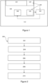
- Figure 1 shows a block diagram of a device 112 having an illuminator 106 and apparatus 100 for monitoring mechanical integrity of an eye-safety component 110 of the illuminator 106, in accordance with the present disclosure.
- the device 112 may be, for example, a cellular telephone, tablet, laptop, watch, or other computing device.
- the apparatus 100 comprises a transducer 103, a sensor 102 in the form of a microphone, and a processor 104.
- the transducer 103 is operable to generate a vibration in the eye-safety component 110.
- the sensor 102 is operable to sense the vibration in the eye-safety component 110 and to output a signal representative of the sensed vibration.
- the processor 104 is operable to: monitor the signal from the sensor 102; determine if the signal comprises at least one parameter that falls outside of a pre-determined acceptable range, the pre-determined acceptable range being indicative of mechanical integrity of the eye-safety component 110; and initiate a safety action in response to a determination that the at least one parameter falls outside of the pre-determined acceptable range, thereby indicating a loss of mechanical integrity.
- the safety action may comprise transmitting an instruction to the illuminator 106 to modify an intensity of illumination (e.g. to lower the intensity to a safe level) or to cease illumination.
- the safety action may comprise modifying the wavelength of the illuminator or switching the illumination from continuous to pulsed.
- the illuminator 106 comprises an emitter 108 as well as the eye-safety component 110.
- the eye-safety component 110 is configured to provide a shield between the emitter 108 and a user (not shown).
- the eye-safety component 110 may comprise a diffuser and/or a transparent window (e.g. cover glass).
- processor 104 is shown outside of the illuminator 106, it could be incorporated within the illuminator 106 and may be, for example, provided on an integrated circuit (IC) with the sensor 102, the transducer 103 and/or the emitter 108.
- IC integrated circuit
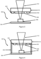
- FIG. 2 shows a method 200, which may be performed by the processor 104, for monitoring mechanical integrity of the eye-safety component 110.
- the method 200 comprises a step 202 of operating a transducer to generate a vibration in the eye-safety component 110.
- the method 200 also comprises a step 204 of obtaining, from the sensor 102, a signal representative of a sensed vibration in the eye-safety component 110 and a step 206 of monitoring the signal.
- a further step 208 comprises determining if the signal comprises at least one parameter that falls outside of a pre-determined acceptable range, the pre-determined acceptable range being indicative of mechanical integrity of the eye-safety component 110.
- a subsequent step 210 comprises initiating a safety action in response to a determination that the at least one parameter falls outside of the pre-determined acceptable range thereby indicating a loss of mechanical integrity.
- the method may further comprise establishing the pre-determined acceptable range (e.g. a threshold value).
- the pre-determined acceptable range may be established by a controller, which may be provided in the illuminator or external thereof (for example, in a host device).
- the pre-determined acceptable range may be of the following form: up to a predefined value; below a predefined value; between predefined values.
- the pre-determined acceptable range may be based on predefined values stored in a memory and/or defined during a calibration step.
- the predefined values may comprise one or more parameters, which may be adjusted during the calibration step.
- the parameters may comprise signal amplitude, signal frequency or signal wavelength.
- the pre-determined acceptable range may be established using an artificial neural network (ANN).
- ANN artificial neural network
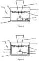
- Figure 3 shows a side schematic view of a first (open) illuminator 300 in accordance with the present disclosure.
- the first illuminator 300 has a similar structure to that of the illuminator 106 and comprises a transducer 303, in the form of a piezoelectric transducer, and a sensor 302, in the form of a microphone.
- An emitter 306 in the form of a vertical cavity surface emitting laser (VCSEL), is mounted on a substrate 304 and is arranged to emit light in the form of a laser beam 312 through a diffuser 308 and a glass window 310. Together, the diffuser 308 and glass window 310 form the eye-safety components 110.
- VCSEL vertical cavity surface emitting laser
- a processor (similar to the processor 104 of Figure 1 ), is provided in communication with the transducer 303, the sensor 302 and the emitter 306.
- the transducer 303 and the sensor 302 are both mounted in direct contact with the glass window 310 of the eye-safety components 110.
- the transducer 303, the sensor 302, or both may be mounted in direct contact with the diffuser 308.
- the transducer 303 and the sensor 302 are located on or close to the eye-safety components 110 to ensure a quick response and good signal quality.
- metallic traces or other electrical connectors e.g. wires may be provided to route electrical signals from the transducer 303 and/or the sensor 302 to the processor and/or emitter 306.
- the transducer 303 is operable to generate a vibration in the glass window 310 and the sensor 302 is operable to sense the vibration and to output a signal representative of the sensed vibration to the processor.
- the processor is operable to: monitor the signal from the sensor 302; determine if the signal comprises at least one parameter that falls outside of a pre-determined acceptable range, the pre-determined acceptable range being indicative of mechanical integrity of the glass window 310; and initiate a safety action in response to a determination that the at least one parameter falls outside of the pre-determined acceptable range, thereby indicating a loss of mechanical integrity.
- the safety action may comprise transmitting an instruction to the illuminator 300 to modify an intensity of illumination (e.g. to lower the intensity to a safe level) or to cease illumination.
- the safety action may comprise modifying the wavelength of the illuminator or switching the illumination from continuous to pulsed.
- FIG 4 shows a side schematic view of a second (closed) illuminator 400 in accordance with the present disclosure.
- the second illuminator 400 is similar to the first illuminator 300 and therefore the same reference numerals are included to indicate similar features.
- the second illuminator 400 is housed in a package or module including sidewalls 402 between the substrate 304 and the glass window 310.
- the second illuminator 400 may therefore be airtight or hermetically sealed and may contain a well-defined fluid (e.g. gas).
- the sensor 302 may sense a vibration signal generated in the diffuser and/or glass window 310, after it has travelled through the fluid such that any leaks or fluid ingression can be detected by a change in the vibration signal.
- FIG. 5 shows a side schematic view of a third (further) illuminator 500 in accordance with the present disclosure.
- the third illuminator 500 is similar to the second illuminator 400 and therefore the same reference numerals are included to indicate similar features.
- the sensor 302 instead of the sensor 302 of Figure 4 being mounted on the glass window 310, in Figure 5 , the sensor 302 is mounted on the substrate 304. In some embodiments, both the transducer 303 and the sensor 302 may be mounted on the substrate 304.
- metallic traces or other electrical connectors e.g. wires
- Figure 6 shows a side schematic view of a fourth (another) illuminator 600 in accordance with the present disclosure.
- the fourth illuminator 600 is similar to the third illuminator 500 and therefore the same reference numerals are included to indicate similar features.
- metallic traces (i.e. connectors) 602 providing a path for electrical signals between the transducer 303 and the substrate 304, are shown.
- a signal to operate the transducer to induce a vibration may be controlled by a processor provided on the substrate 304.
- the processor will additionally determine if the signal from the sensor 302 comprises at least one parameter that falls outside of a pre-determined acceptable range, the pre-determined acceptable range being indicative of mechanical integrity of the glass window 310.
- the processor also initiates a safety action in response to a determination that the at least one parameter falls outside of the pre-determined acceptable range, thereby indicating a loss of mechanical integrity. For example, the processor may transmit a trigger to shut-off power to the emitter 306 to prevent further illumination in the case of a loss of integrity of the eye-safety components.
- Figure 7 shows a side schematic view of a fifth (combined) illuminator 700 in accordance with the present disclosure.
- the fifth illuminator 700 is similar to the fourth illuminator 600 and therefore the same reference numerals are included to indicate similar features.
- the transducer 303 and the sensor 302 are combined into one component 702 that performs the functions of both the transducer 303 and sensor 302.
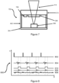
- FIG 8 shows a first (pulsed) timing diagram 800 illustrating different signals generated during operation of the illuminator 106 of Figure 1 . It will be understood that the illuminators 300, 400, 500, 600 and 700 may also operate in a similar manner.
- the timing diagram 800 includes an x-axis representing time and a y-axis representing signal amplitude/intensity. Arbitrary units (AU) are shown, as the diagram is for illustrative purposes only.
- the waveforms shown represent a transducer signal intensity 802, a vibration signal amplitude 804, a gated vibration signal amplitude 806, a noise signal amplitude 808, and a detection gate signal amplitude 810 which are purely illustrative and other shapes of these waveforms may be present in a real device.
- the timing diagram 800 shows a pulsed vibration signal 802 from the transducer. This results in a vibration signal 804 that passes through the eye safety components.
- the vibration signal 804 propagates in the eye-safety components and is transmitted through the sidewalls and enclosed medium. Accordingly, the vibration signal 804 is sensed by the sensor, which is provided either on the eye-safety components or elsewhere in the illuminator.
- a gated detection method is used by generation of the detection gate signal 810, which is timed to isolate a portion of the vibration signal 804, which is denoted as the gated vibration signal 806, and which results from transmission of the vibration signal 804 in the eye-safety components.
- the gated vibration signal 806, which is sensed by the sensor is therefore the product of the detection gate signal 810 and the vibration signal 804.
- the noise signal 808 is also present.
- the transducer may not induce vibrations at a resonant frequency of the glass window.
- the vibration signal 804 may be relatively small and the resulting gated vibration signal 806 is similarly small.
- the gated vibration signal 806 is delayed in time with respect to the transducer signal 802. This is solely a result of the speed of sound in the medium, and therefore it allows the parameters for the detection gate signal 810 to be easily determined.
- a detection gate signal 810 that fully overlaps the vibration signal 804 could be used.
- the vibration signal 804 or the gated vibration signal 806 By monitoring the vibration signal 804 or the gated vibration signal 806, it is possible to check the mechanical integrity of the eye-safety components. As acoustic waves are very sensitive to structural defects, it is possible to observe the status of the eye-safety components any time, while using the transducer.
- the vibration signal amplitude is measured to indicate the mechanical integrity of the eye-safety components. This indication could be found by storing a value for the vibration signal amplitude in memory and comparing this value to a new measured value using the processor.
- any difference in the values would correspond to a mechanical integrity failure in the eye-safety components.
- the comparison may take into account variability in the values due to system tolerances and therefore an acceptable range may be permitted around a typical value such that the safety action is only triggered when the vibration signal amplitude is outside of the acceptable range.
- the spectral components of the vibration signal could be measured to indicate the mechanical integrity of the eye-safety components. This indication could be found by storing a value for the spectral components, e.g. as found with a Fourier transform, in memory and comparing this value to a new measured value using the processor. As above, any difference in the values (taking into account an acceptable tolerance level) may correspond to a mechanical integrity failure in the eye-safety components.
- a vibration signal decay time could be measured to indicate the mechanical integrity of the eye-safety components. This indication could be found by storing a value for the vibration signal decay time in memory and comparing this value to a new measured value using the processor. Again, any difference in the values (taking into account an acceptable tolerance level) would correspond to a mechanical integrity failure in the eye-safety components.
- the amplitude, voltage or frequency required to drive the transducer could be measured to indicate the mechanical integrity of the eye-safety components. This indication could be found by storing a value for the amplitude, voltage or frequency in memory and comparing these values to new measured values using the processor. As above, any difference in the values (taking into account an acceptable tolerance level) would correspond to a mechanical integrity failure in the eye-safety components.
- the sensors may comprise standard microphones, a custom-made microelectromechanical system (MEMS) based microphone may be employed to achieve a sensitivity of up to 1-10V/Pa.
- MEMS microelectromechanical system
- a phononic structure may be provided to improve a signal-to-noise ratio of the vibration signal.
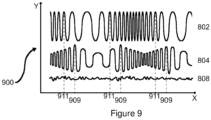
- FIG 9 shows a second (continuous) timing diagram 900 illustrating different signals generated during continuous operation of the transducer 103 of Figure 1 .
- the second (continuous) timing diagram 900 is similar to the first (pulsed) timing diagram 800 and therefore the same reference numerals are included to indicate similar features.
- the timing diagram 900 includes an x-axis representing time and a y-axis representing signal amplitude/intensity.
- Arbitrary units (AU) are shown, as the diagram is for illustrative purposes only.
- the waveforms shown represent a transducer signal intensity 802, a vibration signal amplitude 804, and a noise signal amplitude 808, which are purely illustrative and other shapes of these waveforms may be present in a real device.
- the timing diagram 900 shows the vibration signal 802 as a continuous signal from the transducer that sweeps a pre-determined frequency range. This results in the vibration signal 804.
- the vibration signal 804 propagates in the eye-safety components and is also transmitted through the sidewalls and enclosed medium. Accordingly, the vibration signal 804 is sensed by the sensor, which is provided either on the eye-safety components or elsewhere in the illuminator.
- the vibration signal 804 is delayed from the transducer signal 802 by an amount of time corresponding to the speed of sound in the eye-safety components. This amount of time is illustrated in figure 9 as a time difference between a label 909 and a label 911. An oscillation frequency of the transducer signal 802 that is closest to a resonant frequency of the window is labelled as 911. The label 909 indicates the same resonant frequency in the vibration signal 804 which is delayed due to the speed of sound in the eye-safety components.
- the delay between labels 911 and 909 may be used to indicate the mechanical integrity of the eye-safety components. This indication could be found by storing a value for the time difference between labels 911 and 909 in memory and comparing this value to a new measured value using the processor. Here, any difference in the values (taking into account an acceptable tolerance level) would correspond to a mechanical integrity failure in the eye-safety components.
- the resonant frequency of the eye-safety components when measured by the sensor i.e. corresponding to label 909 on the vibration signal 804
- the resonant frequency of the eye-safety components when measured by the sensor could be used to indicate the mechanical integrity of the eye-safety components.
- This indication could be found by storing a value for the resonant frequency of the vibration signal 804 in memory and comparing this value to a new measured value using the processor.
- any difference in the values would correspond to a mechanical integrity failure in the eye-safety components.
- an amplitude of the vibration signal 804 may be used to indicate the mechanical integrity of the eye-safety components. This indication could be found by storing a value for the amplitude of the vibration signal 804 in memory and comparing this value to a new measured value using the processor. Here, any difference in the values (taking into account an acceptable tolerance level) would correspond to a mechanical integrity failure in the eye-safety components.
- examples of the present disclosure provide a method and apparatus, which use mechanical vibrations to probe the mechanical properties of eye-safety components for illuminators, to monitor the integrity of the eye-safety component and to perform a safety action such as a shutdown of the emitter if a change occurs.
- Embodiments of the present disclosure can be employed in many different applications including world and front facing illuminators for 3D sensing (using e.g. time of flight (ToF), pattern or stereo approaches) or augmented reality, for example, in gaming, industrial, educational, automotive (e.g. for driver monitoring) and other industries.
- world and front facing illuminators for 3D sensing using e.g. time of flight (ToF), pattern or stereo approaches
- augmented reality for example, in gaming, industrial, educational, automotive (e.g. for driver monitoring) and other industries.
Landscapes
- Physics & Mathematics (AREA)
- General Physics & Mathematics (AREA)
- Immunology (AREA)
- Analytical Chemistry (AREA)
- Pathology (AREA)
- General Health & Medical Sciences (AREA)
- Health & Medical Sciences (AREA)
- Life Sciences & Earth Sciences (AREA)
- Chemical & Material Sciences (AREA)
- Biochemistry (AREA)
- Acoustics & Sound (AREA)
- Engineering & Computer Science (AREA)
- Artificial Intelligence (AREA)
- Signal Processing (AREA)
- Evolutionary Computation (AREA)
- Circuit Arrangement For Electric Light Sources In General (AREA)
- Measurement Of Mechanical Vibrations Or Ultrasonic Waves (AREA)
- Arrangement Of Elements, Cooling, Sealing, Or The Like Of Lighting Devices (AREA)
Claims (18)
- Vorrichtung (100) zum Überwachen mechanischer Integrität einer Augensicherheitskomponente (110) eines Beleuchters (106), wobei die Vorrichtung Folgendes umfasst:einen Wandler (103), betreibbar zum Erzeugen einer Vibration in der Augensicherheitskomponente; undeinen Sensor (102), betreibbar zum Erfassen der Vibration in der Augensicherheitskomponente und zum Ausgeben eines Signals, das die erfasste Vibration repräsentiert; undeinen Prozessor (104), betreibbar zum:Überwachen des Signals von dem Sensor;Bestimmen, ob das Signal mindestens einen Parameter umfasst, der außerhalb eines vorbestimmten Akzeptanzbereichs fällt, wobei der vorbestimmte Akzeptanzbereich eine mechanische Integrität der Augensicherheitskomponente angibt; undEinleiten einer Sicherheitsaktion als Reaktion auf eine Bestimmung, dass der mindestens eine Parameter außerhalb des vorbestimmten Akzeptanzbereichs fällt, wodurch ein Verlust mechanischer Integrität angezeigt wird.
- Vorrichtung nach Anspruch 1, wobei der Wandler auch der Sensor ist.
- Vorrichtung nach Anspruch 1 oder 2, ferner umfassend eine phononische Struktur, vorgesehen in der, auf der, an der, angrenzend an die, herum um die oder verwoben mit der Augensicherheitskomponente, um ein Signal-Rausch-Verhältnis für die erfasste Vibration zu verbessern.
- Vorrichtung nach einem vorhergehenden Anspruch, wobei der Prozessor betreibbar ist zum Detektieren einer Änderung von Umgebungsbedingungen innerhalb des Beleuchters auf der Grundlage des Signals von dem Sensor.
- Vorrichtung nach einem vorhergehenden Anspruch, wobei der Prozessor betreibbar ist zum Einleiten der Sicherheitsaktion durch Senden einer Anweisung an den Beleuchter, eine Intensität der Beleuchtung zu modifizieren.
- Vorrichtung nach einem vorhergehenden Anspruch, wobei der Prozessor betreibbar ist zum Einleiten der Sicherheitsaktion durch Senden einer Anweisung an den Beleuchter, eine Beleuchtung abzubrechen.
- Vorrichtung nach einem vorhergehenden Anspruch, wobei der Sensor umfasst: ein Mikrofon und/oder einen Ultraschallwandler und/oder einen piezoelektrischen Wandler und/oder einen spektroskopischen Ultraschall-Resonanz-Sensor.
- Vorrichtung nach einem vorhergehenden Anspruch, wobei die Vibration bei einer vorbestimmten Frequenz liegt, und wobei der Prozessor betreibbar ist zum Verwenden der vorbestimmten Frequenz in einem Verfahren zur Lock-In-Detektion und/oder einem Verfahren zur getasteten Detektion, wenn das Signal von dem Sensor überwacht wird.
- Vorrichtung nach einem vorhergehenden Anspruch, ferner umfassend: einen Signalgenerator und/oder einen Verstärker und/oder ein Filter und/oder einen Lock-In-Detektor und/oder einen Akzeptanzbereichsdetektor.
- Beleuchter, der Folgendes umfasst:mindestens einen Emitter;eine Augensicherheitskomponente, die einen Schutzschirm zwischen dem mindestens einen Emitter und einem Benutzer bereitstellt; unddie Vorrichtung nach einem vorhergehenden Anspruch.
- Beleuchter nach Anspruch 10, wobei der Sensor eingerichtet ist zum direkten Erfassen der Vibration in der Augensicherheitskomponente.
- Beleuchter nach Anspruch 10, wobei der Sensor eingerichtet ist zum indirekten Erfassen der Vibration in der Augensicherheitskomponente durch Empfangen einer Eingabe über einen Wellenleiter oder ein anderes Medium.
- Beleuchter nach einem der Ansprüche 10 bis 12, wobei der mindestens eine Emitter einen Laser umfasst.
- Beleuchter nach einem der Ansprüche 10 bis 13, wobei die Augensicherheitskomponente ein Glassubstrat und/oder einen Diffusor umfasst.
- Einrichtung, die eine Vorrichtung nach einem der Ansprüche 1 bis 9 oder einen Beleuchter nach einem der Ansprüche 10 bis 14 umfasst.
- Verfahren (200) zum Überwachen mechanischer Integrität einer Augensicherheitskomponente eines Beleuchters, wobei das Verfahren Folgendes umfasst:Betreiben (202) eines Wandlers zum Erzeugen einer Vibration in der Augensicherheitskomponente;Erhalten (204), von einem Sensor, eines Signals, das eine erfasste Vibration in der Augensicherheitskomponente repräsentiert;Überwachen (206) des Signals;Bestimmen (208), ob das Signal mindestens einen Parameter umfasst, der außerhalb eines vorbestimmten Akzeptanzbereichs fällt, wobei der vorbestimmte Akzeptanzbereich eine mechanische Integrität der Augensicherheitskomponente angibt; undEinleiten (210) einer Sicherheitsaktion als Reaktion auf eine Bestimmung, dass der mindestens eine Parameter außerhalb des vorbestimmten Akzeptanzbereichs fällt, wodurch ein Verlust mechanischer Integrität angezeigt wird.
- Verfahren nach Anspruch 16, ferner umfassend Erstellen des vorbestimmten Akzeptanzbereichs unter Verwendung eines künstlichen neuronalen Netzes.
- Nichtflüchtiges computerlesbares Medium, das darauf Programmanweisungen gespeichert hat zum Veranlassen mindestens eines Prozessors nach Anspruch 1 zum Durchführen des Verfahrens nach Anspruch 16 oder 17.
Applications Claiming Priority (2)
| Application Number | Priority Date | Filing Date | Title |
|---|---|---|---|
| US201962941966P | 2019-11-29 | 2019-11-29 | |
| PCT/SG2020/050665 WO2021107863A1 (en) | 2019-11-29 | 2020-11-16 | Apparatus for monitoring mechanical integrity of an eye-safety component of an illuminator |
Publications (2)
| Publication Number | Publication Date |
|---|---|
| EP4065938A1 EP4065938A1 (de) | 2022-10-05 |
| EP4065938B1 true EP4065938B1 (de) | 2023-10-25 |
Family
ID=73598930
Family Applications (1)
| Application Number | Title | Priority Date | Filing Date |
|---|---|---|---|
| EP20815969.9A Active EP4065938B1 (de) | 2019-11-29 | 2020-11-16 | Vorrichtung zur überwachung der mechanischen integrität einer augensicherheitskomponente einer beleuchtungsvorrichtung |
Country Status (4)
| Country | Link |
|---|---|
| US (1) | US20230094981A1 (de) |
| EP (1) | EP4065938B1 (de) |
| CN (1) | CN114761770B (de) |
| WO (1) | WO2021107863A1 (de) |
Families Citing this family (1)
| Publication number | Priority date | Publication date | Assignee | Title |
|---|---|---|---|---|
| EP4064963B1 (de) * | 2019-11-29 | 2024-08-07 | ams Sensors Singapore Pte. Ltd. | Vorrichtung zur überwachung der mechanischen integrität einer augensicherheitskomponente einer beleuchtungsvorrichtung |
Family Cites Families (21)
| Publication number | Priority date | Publication date | Assignee | Title |
|---|---|---|---|---|
| US5179860A (en) * | 1989-10-04 | 1993-01-19 | Iwatsu Electric Co., Ltd. | Defect detecting method and apparatus |
| US6518539B2 (en) * | 2000-10-23 | 2003-02-11 | The Regents Of The University Of California | Method for producing damage resistant optics |
| DE10256102B4 (de) * | 2002-11-29 | 2005-09-15 | Daimlerchrysler Ag | Fahrzeugscheinwerfer und Verfahren zum Betrieb eines solchen |
| JP4088188B2 (ja) * | 2003-04-07 | 2008-05-21 | セイコーエプソン株式会社 | プロジェクタ |
| US7330250B2 (en) * | 2004-05-18 | 2008-02-12 | Agilent Technologies, Inc. | Nondestructive evaluation of subsurface damage in optical elements |
| CN101341000B (zh) * | 2005-12-15 | 2011-08-24 | 通快机床两合公司 | 用于激光装置的光学元件的状态识别的方法以及激光装置 |
| WO2008056297A1 (en) * | 2006-11-08 | 2008-05-15 | Philips Intellectual Property & Standards Gmbh | Laser projector with automatic security |
| CN102681312B (zh) * | 2011-03-16 | 2015-06-24 | 宏瞻科技股份有限公司 | 激光投影系统的人眼安全保护系统 |
| CN103760243A (zh) * | 2014-02-26 | 2014-04-30 | 长沙理工大学 | 一种微裂纹无损检测装置及方法 |
| DE102015003341B4 (de) * | 2015-03-14 | 2025-02-27 | HELLA GmbH & Co. KGaA | Verfahren zur Bestimmung der räumlichen Lage einer Beschädigung an einem Glaskörper |
| US20170276618A1 (en) * | 2016-03-23 | 2017-09-28 | Apple Inc. | Glass breakage detection |
| US10682675B2 (en) * | 2016-11-01 | 2020-06-16 | Texas Instruments Incorporated | Ultrasonic lens cleaning system with impedance monitoring to detect faults or degradation |
| DE102016224988A1 (de) * | 2016-12-14 | 2018-06-14 | Universität Stuttgart | Verfahren und Vorrichtung zum Nachweis von Defekten in einem Objekt |
| US11042026B2 (en) * | 2017-02-24 | 2021-06-22 | Texas Instruments Incorporated | Transducer-induced heating and cleaning |
| US10527843B2 (en) * | 2017-05-12 | 2020-01-07 | International Business Machines Corporation | Ultra-sonic self-cleaning system |
| CN107608167A (zh) * | 2017-10-11 | 2018-01-19 | 深圳奥比中光科技有限公司 | 激光投影装置及其安全控制方法 |
| CN207623289U (zh) * | 2017-12-11 | 2018-07-17 | 苏州大学 | 光学元件抛光表面质量声发射检测装置 |
| US10928362B2 (en) * | 2018-05-04 | 2021-02-23 | Raytheon Technologies Corporation | Nondestructive inspection using dual pulse-echo ultrasonics and method therefor |
| US11073440B2 (en) * | 2018-07-31 | 2021-07-27 | Namuga, Co., Ltd. | Hermetic sealed beam projector module and method for manufacturing the same |
| EP3734267A1 (de) * | 2019-05-01 | 2020-11-04 | Northrop Grumman Innovation Systems, Inc. | Inspektionsvorrichtungen mit laseremittern und optischen mikrofonen sowie zugehörige systeme und verfahren |
| EP4064963B1 (de) * | 2019-11-29 | 2024-08-07 | ams Sensors Singapore Pte. Ltd. | Vorrichtung zur überwachung der mechanischen integrität einer augensicherheitskomponente einer beleuchtungsvorrichtung |
-
2020
- 2020-11-16 US US17/793,153 patent/US20230094981A1/en not_active Abandoned
- 2020-11-16 WO PCT/SG2020/050665 patent/WO2021107863A1/en not_active Ceased
- 2020-11-16 CN CN202080082946.0A patent/CN114761770B/zh active Active
- 2020-11-16 EP EP20815969.9A patent/EP4065938B1/de active Active
Also Published As
| Publication number | Publication date |
|---|---|
| CN114761770A (zh) | 2022-07-15 |
| US20230094981A1 (en) | 2023-03-30 |
| WO2021107863A1 (en) | 2021-06-03 |
| EP4065938A1 (de) | 2022-10-05 |
| CN114761770B (zh) | 2025-01-03 |
Similar Documents
| Publication | Publication Date | Title |
|---|---|---|
| US8166825B2 (en) | Method and apparatus for noise reduction in ultrasound detection | |
| KR101912972B1 (ko) | 초음파 검사 장치 및 초음파 검사 방법 | |
| WO2012114730A1 (ja) | 光音響計測装置及び光音響信号検出方法 | |
| EP3742193A1 (de) | Lasersensormodul mit verschmutzungserkennung | |
| EP4064963B1 (de) | Vorrichtung zur überwachung der mechanischen integrität einer augensicherheitskomponente einer beleuchtungsvorrichtung | |
| CN103152685B (zh) | 基于fp干涉原理的光纤传声器 | |
| EP3199946B1 (de) | Verformungserkennungsvorrichtung | |
| JP6830545B2 (ja) | レーザーベースの粒子検出器の動作条件を決定する方法 | |
| EP4065938B1 (de) | Vorrichtung zur überwachung der mechanischen integrität einer augensicherheitskomponente einer beleuchtungsvorrichtung | |
| CN110411552A (zh) | 光学声传感器工作点偏离判断方法及其装置 | |
| US11940379B2 (en) | Device for measuring a relative humidity level inside the enclosure of a watch case | |
| JP6880311B2 (ja) | 超音波プローブ、超音波プローブの制御方法および超音波プローブ検査システム | |
| EP3811053B1 (de) | Lasersensormodul zur messung einer teilchendichte umfassend einen detektor ausgebildet zur bereitstellung eines signals zur anzeige von verschmutzung eines emissionsfensters, verfahren und computerprogramm | |
| JP6570343B2 (ja) | 光干渉断層計、面発光レーザ | |
| JP2008309740A (ja) | 車両衝突検知装置 | |
| JP2002540417A (ja) | 光弾性変調器のための統合診断装置 | |
| CN120801947B (zh) | 一种定位变压器局部放电缺陷的方法及系统 | |
| HK40072624A (en) | Device for measuring a relative humidity level inside the enclosure of a watch case | |
| HK40072627A (en) | Assembly for measuring the relative humidity level inside a watch case | |
| JP2021162466A (ja) | 状態検出装置、電磁波走査装置における透過部の状態検出方法 | |
| Chen et al. | Photo-electromotive-force sensor-based laser vibrometer with gain-switched laser diode |
Legal Events
| Date | Code | Title | Description |
|---|---|---|---|
| STAA | Information on the status of an ep patent application or granted ep patent |
Free format text: STATUS: UNKNOWN |
|
| STAA | Information on the status of an ep patent application or granted ep patent |
Free format text: STATUS: THE INTERNATIONAL PUBLICATION HAS BEEN MADE |
|
| PUAI | Public reference made under article 153(3) epc to a published international application that has entered the european phase |
Free format text: ORIGINAL CODE: 0009012 |
|
| STAA | Information on the status of an ep patent application or granted ep patent |
Free format text: STATUS: REQUEST FOR EXAMINATION WAS MADE |
|
| 17P | Request for examination filed |
Effective date: 20220629 |
|
| AK | Designated contracting states |
Kind code of ref document: A1 Designated state(s): AL AT BE BG CH CY CZ DE DK EE ES FI FR GB GR HR HU IE IS IT LI LT LU LV MC MK MT NL NO PL PT RO RS SE SI SK SM TR |
|
| DAV | Request for validation of the european patent (deleted) | ||
| DAX | Request for extension of the european patent (deleted) | ||
| GRAP | Despatch of communication of intention to grant a patent |
Free format text: ORIGINAL CODE: EPIDOSNIGR1 |
|
| P01 | Opt-out of the competence of the unified patent court (upc) registered |
Effective date: 20230613 |
|
| STAA | Information on the status of an ep patent application or granted ep patent |
Free format text: STATUS: GRANT OF PATENT IS INTENDED |
|
| RIC1 | Information provided on ipc code assigned before grant |
Ipc: G01N 29/44 20060101ALI20230703BHEP Ipc: G01N 29/34 20060101ALI20230703BHEP Ipc: G01N 29/11 20060101ALI20230703BHEP Ipc: G01H 1/12 20060101AFI20230703BHEP |
|
| INTG | Intention to grant announced |
Effective date: 20230720 |
|
| GRAS | Grant fee paid |
Free format text: ORIGINAL CODE: EPIDOSNIGR3 |
|
| GRAA | (expected) grant |
Free format text: ORIGINAL CODE: 0009210 |
|
| STAA | Information on the status of an ep patent application or granted ep patent |
Free format text: STATUS: THE PATENT HAS BEEN GRANTED |
|
| AK | Designated contracting states |
Kind code of ref document: B1 Designated state(s): AL AT BE BG CH CY CZ DE DK EE ES FI FR GB GR HR HU IE IS IT LI LT LU LV MC MK MT NL NO PL PT RO RS SE SI SK SM TR |
|
| REG | Reference to a national code |
Ref country code: GB Ref legal event code: FG4D |
|
| REG | Reference to a national code |
Ref country code: CH Ref legal event code: EP |
|
| REG | Reference to a national code |
Ref country code: DE Ref legal event code: R096 Ref document number: 602020019958 Country of ref document: DE |
|
| REG | Reference to a national code |
Ref country code: IE Ref legal event code: FG4D |
|
| REG | Reference to a national code |
Ref country code: LT Ref legal event code: MG9D |
|
| REG | Reference to a national code |
Ref country code: NL Ref legal event code: MP Effective date: 20231025 |
|
| REG | Reference to a national code |
Ref country code: AT Ref legal event code: MK05 Ref document number: 1625104 Country of ref document: AT Kind code of ref document: T Effective date: 20231025 |
|
| PG25 | Lapsed in a contracting state [announced via postgrant information from national office to epo] |
Ref country code: NL Free format text: LAPSE BECAUSE OF FAILURE TO SUBMIT A TRANSLATION OF THE DESCRIPTION OR TO PAY THE FEE WITHIN THE PRESCRIBED TIME-LIMIT Effective date: 20231025 |
|
| PG25 | Lapsed in a contracting state [announced via postgrant information from national office to epo] |
Ref country code: GR Free format text: LAPSE BECAUSE OF FAILURE TO SUBMIT A TRANSLATION OF THE DESCRIPTION OR TO PAY THE FEE WITHIN THE PRESCRIBED TIME-LIMIT Effective date: 20240126 |
|
| PG25 | Lapsed in a contracting state [announced via postgrant information from national office to epo] |
Ref country code: IS Free format text: LAPSE BECAUSE OF FAILURE TO SUBMIT A TRANSLATION OF THE DESCRIPTION OR TO PAY THE FEE WITHIN THE PRESCRIBED TIME-LIMIT Effective date: 20240225 |
|
| PG25 | Lapsed in a contracting state [announced via postgrant information from national office to epo] |
Ref country code: LT Free format text: LAPSE BECAUSE OF FAILURE TO SUBMIT A TRANSLATION OF THE DESCRIPTION OR TO PAY THE FEE WITHIN THE PRESCRIBED TIME-LIMIT Effective date: 20231025 |
|
| PG25 | Lapsed in a contracting state [announced via postgrant information from national office to epo] |
Ref country code: AT Free format text: LAPSE BECAUSE OF FAILURE TO SUBMIT A TRANSLATION OF THE DESCRIPTION OR TO PAY THE FEE WITHIN THE PRESCRIBED TIME-LIMIT Effective date: 20231025 |
|
| PG25 | Lapsed in a contracting state [announced via postgrant information from national office to epo] |
Ref country code: ES Free format text: LAPSE BECAUSE OF FAILURE TO SUBMIT A TRANSLATION OF THE DESCRIPTION OR TO PAY THE FEE WITHIN THE PRESCRIBED TIME-LIMIT Effective date: 20231025 |
|
| PG25 | Lapsed in a contracting state [announced via postgrant information from national office to epo] |
Ref country code: LT Free format text: LAPSE BECAUSE OF FAILURE TO SUBMIT A TRANSLATION OF THE DESCRIPTION OR TO PAY THE FEE WITHIN THE PRESCRIBED TIME-LIMIT Effective date: 20231025 Ref country code: IS Free format text: LAPSE BECAUSE OF FAILURE TO SUBMIT A TRANSLATION OF THE DESCRIPTION OR TO PAY THE FEE WITHIN THE PRESCRIBED TIME-LIMIT Effective date: 20240225 Ref country code: GR Free format text: LAPSE BECAUSE OF FAILURE TO SUBMIT A TRANSLATION OF THE DESCRIPTION OR TO PAY THE FEE WITHIN THE PRESCRIBED TIME-LIMIT Effective date: 20240126 Ref country code: ES Free format text: LAPSE BECAUSE OF FAILURE TO SUBMIT A TRANSLATION OF THE DESCRIPTION OR TO PAY THE FEE WITHIN THE PRESCRIBED TIME-LIMIT Effective date: 20231025 Ref country code: BG Free format text: LAPSE BECAUSE OF FAILURE TO SUBMIT A TRANSLATION OF THE DESCRIPTION OR TO PAY THE FEE WITHIN THE PRESCRIBED TIME-LIMIT Effective date: 20240125 Ref country code: AT Free format text: LAPSE BECAUSE OF FAILURE TO SUBMIT A TRANSLATION OF THE DESCRIPTION OR TO PAY THE FEE WITHIN THE PRESCRIBED TIME-LIMIT Effective date: 20231025 Ref country code: PT Free format text: LAPSE BECAUSE OF FAILURE TO SUBMIT A TRANSLATION OF THE DESCRIPTION OR TO PAY THE FEE WITHIN THE PRESCRIBED TIME-LIMIT Effective date: 20240226 |
|
| PG25 | Lapsed in a contracting state [announced via postgrant information from national office to epo] |
Ref country code: SE Free format text: LAPSE BECAUSE OF FAILURE TO SUBMIT A TRANSLATION OF THE DESCRIPTION OR TO PAY THE FEE WITHIN THE PRESCRIBED TIME-LIMIT Effective date: 20231025 Ref country code: RS Free format text: LAPSE BECAUSE OF FAILURE TO SUBMIT A TRANSLATION OF THE DESCRIPTION OR TO PAY THE FEE WITHIN THE PRESCRIBED TIME-LIMIT Effective date: 20231025 Ref country code: PL Free format text: LAPSE BECAUSE OF FAILURE TO SUBMIT A TRANSLATION OF THE DESCRIPTION OR TO PAY THE FEE WITHIN THE PRESCRIBED TIME-LIMIT Effective date: 20231025 Ref country code: NO Free format text: LAPSE BECAUSE OF FAILURE TO SUBMIT A TRANSLATION OF THE DESCRIPTION OR TO PAY THE FEE WITHIN THE PRESCRIBED TIME-LIMIT Effective date: 20240125 Ref country code: LV Free format text: LAPSE BECAUSE OF FAILURE TO SUBMIT A TRANSLATION OF THE DESCRIPTION OR TO PAY THE FEE WITHIN THE PRESCRIBED TIME-LIMIT Effective date: 20231025 Ref country code: HR Free format text: LAPSE BECAUSE OF FAILURE TO SUBMIT A TRANSLATION OF THE DESCRIPTION OR TO PAY THE FEE WITHIN THE PRESCRIBED TIME-LIMIT Effective date: 20231025 |
|
| REG | Reference to a national code |
Ref country code: CH Ref legal event code: PL |
|
| PG25 | Lapsed in a contracting state [announced via postgrant information from national office to epo] |
Ref country code: DK Free format text: LAPSE BECAUSE OF FAILURE TO SUBMIT A TRANSLATION OF THE DESCRIPTION OR TO PAY THE FEE WITHIN THE PRESCRIBED TIME-LIMIT Effective date: 20231025 |
|
| PG25 | Lapsed in a contracting state [announced via postgrant information from national office to epo] |
Ref country code: LU Free format text: LAPSE BECAUSE OF NON-PAYMENT OF DUE FEES Effective date: 20231116 |
|
| PG25 | Lapsed in a contracting state [announced via postgrant information from national office to epo] |
Ref country code: CH Free format text: LAPSE BECAUSE OF NON-PAYMENT OF DUE FEES Effective date: 20231130 |
|
| PG25 | Lapsed in a contracting state [announced via postgrant information from national office to epo] |
Ref country code: CZ Free format text: LAPSE BECAUSE OF FAILURE TO SUBMIT A TRANSLATION OF THE DESCRIPTION OR TO PAY THE FEE WITHIN THE PRESCRIBED TIME-LIMIT Effective date: 20231025 |
|
| REG | Reference to a national code |
Ref country code: DE Ref legal event code: R097 Ref document number: 602020019958 Country of ref document: DE |
|
| PG25 | Lapsed in a contracting state [announced via postgrant information from national office to epo] |
Ref country code: SK Free format text: LAPSE BECAUSE OF FAILURE TO SUBMIT A TRANSLATION OF THE DESCRIPTION OR TO PAY THE FEE WITHIN THE PRESCRIBED TIME-LIMIT Effective date: 20231025 |
|
| PG25 | Lapsed in a contracting state [announced via postgrant information from national office to epo] |
Ref country code: SM Free format text: LAPSE BECAUSE OF FAILURE TO SUBMIT A TRANSLATION OF THE DESCRIPTION OR TO PAY THE FEE WITHIN THE PRESCRIBED TIME-LIMIT Effective date: 20231025 Ref country code: SK Free format text: LAPSE BECAUSE OF FAILURE TO SUBMIT A TRANSLATION OF THE DESCRIPTION OR TO PAY THE FEE WITHIN THE PRESCRIBED TIME-LIMIT Effective date: 20231025 Ref country code: RO Free format text: LAPSE BECAUSE OF FAILURE TO SUBMIT A TRANSLATION OF THE DESCRIPTION OR TO PAY THE FEE WITHIN THE PRESCRIBED TIME-LIMIT Effective date: 20231025 Ref country code: LU Free format text: LAPSE BECAUSE OF NON-PAYMENT OF DUE FEES Effective date: 20231116 Ref country code: IT Free format text: LAPSE BECAUSE OF FAILURE TO SUBMIT A TRANSLATION OF THE DESCRIPTION OR TO PAY THE FEE WITHIN THE PRESCRIBED TIME-LIMIT Effective date: 20231025 Ref country code: EE Free format text: LAPSE BECAUSE OF FAILURE TO SUBMIT A TRANSLATION OF THE DESCRIPTION OR TO PAY THE FEE WITHIN THE PRESCRIBED TIME-LIMIT Effective date: 20231025 Ref country code: DK Free format text: LAPSE BECAUSE OF FAILURE TO SUBMIT A TRANSLATION OF THE DESCRIPTION OR TO PAY THE FEE WITHIN THE PRESCRIBED TIME-LIMIT Effective date: 20231025 Ref country code: CZ Free format text: LAPSE BECAUSE OF FAILURE TO SUBMIT A TRANSLATION OF THE DESCRIPTION OR TO PAY THE FEE WITHIN THE PRESCRIBED TIME-LIMIT Effective date: 20231025 Ref country code: CH Free format text: LAPSE BECAUSE OF NON-PAYMENT OF DUE FEES Effective date: 20231130 |
|
| REG | Reference to a national code |
Ref country code: BE Ref legal event code: MM Effective date: 20231130 |
|
| PG25 | Lapsed in a contracting state [announced via postgrant information from national office to epo] |
Ref country code: MC Free format text: LAPSE BECAUSE OF FAILURE TO SUBMIT A TRANSLATION OF THE DESCRIPTION OR TO PAY THE FEE WITHIN THE PRESCRIBED TIME-LIMIT Effective date: 20231025 |
|
| PG25 | Lapsed in a contracting state [announced via postgrant information from national office to epo] |
Ref country code: MC Free format text: LAPSE BECAUSE OF FAILURE TO SUBMIT A TRANSLATION OF THE DESCRIPTION OR TO PAY THE FEE WITHIN THE PRESCRIBED TIME-LIMIT Effective date: 20231025 |
|
| PLBE | No opposition filed within time limit |
Free format text: ORIGINAL CODE: 0009261 |
|
| STAA | Information on the status of an ep patent application or granted ep patent |
Free format text: STATUS: NO OPPOSITION FILED WITHIN TIME LIMIT |
|
| REG | Reference to a national code |
Ref country code: IE Ref legal event code: MM4A |
|
| 26N | No opposition filed |
Effective date: 20240726 |
|
| PG25 | Lapsed in a contracting state [announced via postgrant information from national office to epo] |
Ref country code: IE Free format text: LAPSE BECAUSE OF NON-PAYMENT OF DUE FEES Effective date: 20231116 |
|
| PG25 | Lapsed in a contracting state [announced via postgrant information from national office to epo] |
Ref country code: BE Free format text: LAPSE BECAUSE OF NON-PAYMENT OF DUE FEES Effective date: 20231130 |
|
| PG25 | Lapsed in a contracting state [announced via postgrant information from national office to epo] |
Ref country code: FR Free format text: LAPSE BECAUSE OF NON-PAYMENT OF DUE FEES Effective date: 20231225 |
|
| PG25 | Lapsed in a contracting state [announced via postgrant information from national office to epo] |
Ref country code: SI Free format text: LAPSE BECAUSE OF FAILURE TO SUBMIT A TRANSLATION OF THE DESCRIPTION OR TO PAY THE FEE WITHIN THE PRESCRIBED TIME-LIMIT Effective date: 20231025 |
|
| PG25 | Lapsed in a contracting state [announced via postgrant information from national office to epo] |
Ref country code: SI Free format text: LAPSE BECAUSE OF FAILURE TO SUBMIT A TRANSLATION OF THE DESCRIPTION OR TO PAY THE FEE WITHIN THE PRESCRIBED TIME-LIMIT Effective date: 20231025 Ref country code: IE Free format text: LAPSE BECAUSE OF NON-PAYMENT OF DUE FEES Effective date: 20231116 Ref country code: FR Free format text: LAPSE BECAUSE OF NON-PAYMENT OF DUE FEES Effective date: 20231225 Ref country code: BE Free format text: LAPSE BECAUSE OF NON-PAYMENT OF DUE FEES Effective date: 20231130 |
|
| PGFP | Annual fee paid to national office [announced via postgrant information from national office to epo] |
Ref country code: DE Payment date: 20241121 Year of fee payment: 5 |
|
| PG25 | Lapsed in a contracting state [announced via postgrant information from national office to epo] |
Ref country code: FI Free format text: LAPSE BECAUSE OF FAILURE TO SUBMIT A TRANSLATION OF THE DESCRIPTION OR TO PAY THE FEE WITHIN THE PRESCRIBED TIME-LIMIT Effective date: 20231025 |
|
| GBPC | Gb: european patent ceased through non-payment of renewal fee |
Effective date: 20241116 |
|
| PG25 | Lapsed in a contracting state [announced via postgrant information from national office to epo] |
Ref country code: CY Free format text: LAPSE BECAUSE OF FAILURE TO SUBMIT A TRANSLATION OF THE DESCRIPTION OR TO PAY THE FEE WITHIN THE PRESCRIBED TIME-LIMIT; INVALID AB INITIO Effective date: 20201116 |
|
| PG25 | Lapsed in a contracting state [announced via postgrant information from national office to epo] |
Ref country code: HU Free format text: LAPSE BECAUSE OF FAILURE TO SUBMIT A TRANSLATION OF THE DESCRIPTION OR TO PAY THE FEE WITHIN THE PRESCRIBED TIME-LIMIT; INVALID AB INITIO Effective date: 20201116 |
|
| PG25 | Lapsed in a contracting state [announced via postgrant information from national office to epo] |
Ref country code: GB Free format text: LAPSE BECAUSE OF NON-PAYMENT OF DUE FEES Effective date: 20241116 |
|
| PG25 | Lapsed in a contracting state [announced via postgrant information from national office to epo] |
Ref country code: TR Free format text: LAPSE BECAUSE OF FAILURE TO SUBMIT A TRANSLATION OF THE DESCRIPTION OR TO PAY THE FEE WITHIN THE PRESCRIBED TIME-LIMIT Effective date: 20231025 |
|
| REG | Reference to a national code |
Ref country code: DE Ref legal event code: R081 Ref document number: 602020019958 Country of ref document: DE Owner name: AMS-OSRAM ASIA PACIFIC PTE. LTD., SG Free format text: FORMER OWNER: AMS SENSORS SINGAPORE PTE. LTD., SINGAPORE, SG |