EP4066740B1 - Bildgebungsunterstützungsvorrichtung, verfahren zu deren betrieb und betriebsprogramm - Google Patents
Bildgebungsunterstützungsvorrichtung, verfahren zu deren betrieb und betriebsprogramm Download PDFInfo
- Publication number
- EP4066740B1 EP4066740B1 EP20893265.7A EP20893265A EP4066740B1 EP 4066740 B1 EP4066740 B1 EP 4066740B1 EP 20893265 A EP20893265 A EP 20893265A EP 4066740 B1 EP4066740 B1 EP 4066740B1
- Authority
- EP
- European Patent Office
- Prior art keywords
- image
- subject
- imaging
- radiation
- optical
- Prior art date
- Legal status (The legal status is an assumption and is not a legal conclusion. Google has not performed a legal analysis and makes no representation as to the accuracy of the status listed.)
- Active
Links
Images






Classifications
-
- A—HUMAN NECESSITIES
- A61—MEDICAL OR VETERINARY SCIENCE; HYGIENE
- A61B—DIAGNOSIS; SURGERY; IDENTIFICATION
- A61B6/00—Apparatus or devices for radiation diagnosis; Apparatus or devices for radiation diagnosis combined with radiation therapy equipment
- A61B6/04—Positioning of patients; Tiltable beds or the like
- A61B6/0492—Positioning of patients; Tiltable beds or the like using markers or indicia for aiding patient positioning
-
- A—HUMAN NECESSITIES
- A61—MEDICAL OR VETERINARY SCIENCE; HYGIENE
- A61B—DIAGNOSIS; SURGERY; IDENTIFICATION
- A61B5/00—Measuring for diagnostic purposes; Identification of persons
- A61B5/0059—Measuring for diagnostic purposes; Identification of persons using light, e.g. diagnosis by transillumination, diascopy, fluorescence
- A61B5/0077—Devices for viewing the surface of the body, e.g. camera, magnifying lens
-
- A—HUMAN NECESSITIES
- A61—MEDICAL OR VETERINARY SCIENCE; HYGIENE
- A61B—DIAGNOSIS; SURGERY; IDENTIFICATION
- A61B5/00—Measuring for diagnostic purposes; Identification of persons
- A61B5/45—For evaluating or diagnosing the musculoskeletal system or teeth
- A61B5/4538—Evaluating a particular part of the muscoloskeletal system or a particular medical condition
- A61B5/4566—Evaluating the spine
-
- A—HUMAN NECESSITIES
- A61—MEDICAL OR VETERINARY SCIENCE; HYGIENE
- A61B—DIAGNOSIS; SURGERY; IDENTIFICATION
- A61B5/00—Measuring for diagnostic purposes; Identification of persons
- A61B5/45—For evaluating or diagnosing the musculoskeletal system or teeth
- A61B5/4538—Evaluating a particular part of the muscoloskeletal system or a particular medical condition
- A61B5/458—Evaluating the elbow
-
- A—HUMAN NECESSITIES
- A61—MEDICAL OR VETERINARY SCIENCE; HYGIENE
- A61B—DIAGNOSIS; SURGERY; IDENTIFICATION
- A61B5/00—Measuring for diagnostic purposes; Identification of persons
- A61B5/45—For evaluating or diagnosing the musculoskeletal system or teeth
- A61B5/4538—Evaluating a particular part of the muscoloskeletal system or a particular medical condition
- A61B5/4585—Evaluating the knee
-
- A—HUMAN NECESSITIES
- A61—MEDICAL OR VETERINARY SCIENCE; HYGIENE
- A61B—DIAGNOSIS; SURGERY; IDENTIFICATION
- A61B5/00—Measuring for diagnostic purposes; Identification of persons
- A61B5/74—Details of notification to user or communication with user or patient; User input means
- A61B5/742—Details of notification to user or communication with user or patient; User input means using visual displays
- A61B5/7425—Displaying combinations of multiple images regardless of image source, e.g. displaying a reference anatomical image with a live image
-
- A—HUMAN NECESSITIES
- A61—MEDICAL OR VETERINARY SCIENCE; HYGIENE
- A61B—DIAGNOSIS; SURGERY; IDENTIFICATION
- A61B5/00—Measuring for diagnostic purposes; Identification of persons
- A61B5/74—Details of notification to user or communication with user or patient; User input means
- A61B5/742—Details of notification to user or communication with user or patient; User input means using visual displays
- A61B5/743—Displaying an image simultaneously with additional graphical information, e.g. symbols, charts, function plots
-
- A—HUMAN NECESSITIES
- A61—MEDICAL OR VETERINARY SCIENCE; HYGIENE
- A61B—DIAGNOSIS; SURGERY; IDENTIFICATION
- A61B6/00—Apparatus or devices for radiation diagnosis; Apparatus or devices for radiation diagnosis combined with radiation therapy equipment
- A61B6/08—Auxiliary means for directing the radiation beam to a particular spot, e.g. using light beams
-
- A—HUMAN NECESSITIES
- A61—MEDICAL OR VETERINARY SCIENCE; HYGIENE
- A61B—DIAGNOSIS; SURGERY; IDENTIFICATION
- A61B6/00—Apparatus or devices for radiation diagnosis; Apparatus or devices for radiation diagnosis combined with radiation therapy equipment
- A61B6/42—Arrangements for detecting radiation specially adapted for radiation diagnosis
- A61B6/4283—Arrangements for detecting radiation specially adapted for radiation diagnosis characterised by a detector unit being housed in a cassette
-
- A—HUMAN NECESSITIES
- A61—MEDICAL OR VETERINARY SCIENCE; HYGIENE
- A61B—DIAGNOSIS; SURGERY; IDENTIFICATION
- A61B6/00—Apparatus or devices for radiation diagnosis; Apparatus or devices for radiation diagnosis combined with radiation therapy equipment
- A61B6/44—Constructional features of apparatus for radiation diagnosis
- A61B6/4417—Constructional features of apparatus for radiation diagnosis related to combined acquisition of different diagnostic modalities
-
- A—HUMAN NECESSITIES
- A61—MEDICAL OR VETERINARY SCIENCE; HYGIENE
- A61B—DIAGNOSIS; SURGERY; IDENTIFICATION
- A61B6/00—Apparatus or devices for radiation diagnosis; Apparatus or devices for radiation diagnosis combined with radiation therapy equipment
- A61B6/44—Constructional features of apparatus for radiation diagnosis
- A61B6/4476—Constructional features of apparatus for radiation diagnosis related to motor-assisted motion of the source unit
-
- A—HUMAN NECESSITIES
- A61—MEDICAL OR VETERINARY SCIENCE; HYGIENE
- A61B—DIAGNOSIS; SURGERY; IDENTIFICATION
- A61B6/00—Apparatus or devices for radiation diagnosis; Apparatus or devices for radiation diagnosis combined with radiation therapy equipment
- A61B6/46—Arrangements for interfacing with the operator or the patient
- A61B6/461—Displaying means of special interest
- A61B6/463—Displaying means of special interest characterised by displaying multiple images or images and diagnostic data on one display
-
- A—HUMAN NECESSITIES
- A61—MEDICAL OR VETERINARY SCIENCE; HYGIENE
- A61B—DIAGNOSIS; SURGERY; IDENTIFICATION
- A61B6/00—Apparatus or devices for radiation diagnosis; Apparatus or devices for radiation diagnosis combined with radiation therapy equipment
- A61B6/46—Arrangements for interfacing with the operator or the patient
- A61B6/461—Displaying means of special interest
- A61B6/465—Displaying means of special interest adapted to display user selection data, e.g. graphical user interface, icons or menus
-
- A—HUMAN NECESSITIES
- A61—MEDICAL OR VETERINARY SCIENCE; HYGIENE
- A61B—DIAGNOSIS; SURGERY; IDENTIFICATION
- A61B6/00—Apparatus or devices for radiation diagnosis; Apparatus or devices for radiation diagnosis combined with radiation therapy equipment
- A61B6/50—Apparatus or devices for radiation diagnosis; Apparatus or devices for radiation diagnosis combined with radiation therapy equipment specially adapted for specific body parts; specially adapted for specific clinical applications
- A61B6/505—Apparatus or devices for radiation diagnosis; Apparatus or devices for radiation diagnosis combined with radiation therapy equipment specially adapted for specific body parts; specially adapted for specific clinical applications for diagnosis of bone
-
- A—HUMAN NECESSITIES
- A61—MEDICAL OR VETERINARY SCIENCE; HYGIENE
- A61B—DIAGNOSIS; SURGERY; IDENTIFICATION
- A61B6/00—Apparatus or devices for radiation diagnosis; Apparatus or devices for radiation diagnosis combined with radiation therapy equipment
- A61B6/52—Devices using data or image processing specially adapted for radiation diagnosis
- A61B6/5211—Devices using data or image processing specially adapted for radiation diagnosis involving processing of medical diagnostic data
- A61B6/5229—Devices using data or image processing specially adapted for radiation diagnosis involving processing of medical diagnostic data combining image data of a patient, e.g. combining a functional image with an anatomical image
- A61B6/5247—Devices using data or image processing specially adapted for radiation diagnosis involving processing of medical diagnostic data combining image data of a patient, e.g. combining a functional image with an anatomical image combining images from an ionising-radiation diagnostic technique and a non-ionising radiation diagnostic technique, e.g. X-ray and ultrasound
-
- A—HUMAN NECESSITIES
- A61—MEDICAL OR VETERINARY SCIENCE; HYGIENE
- A61B—DIAGNOSIS; SURGERY; IDENTIFICATION
- A61B6/00—Apparatus or devices for radiation diagnosis; Apparatus or devices for radiation diagnosis combined with radiation therapy equipment
- A61B6/54—Control of apparatus or devices for radiation diagnosis
-
- A—HUMAN NECESSITIES
- A61—MEDICAL OR VETERINARY SCIENCE; HYGIENE
- A61B—DIAGNOSIS; SURGERY; IDENTIFICATION
- A61B6/00—Apparatus or devices for radiation diagnosis; Apparatus or devices for radiation diagnosis combined with radiation therapy equipment
- A61B6/54—Control of apparatus or devices for radiation diagnosis
- A61B6/545—Control of apparatus or devices for radiation diagnosis involving automatic set-up of acquisition parameters
-
- G—PHYSICS
- G06—COMPUTING OR CALCULATING; COUNTING
- G06T—IMAGE DATA PROCESSING OR GENERATION, IN GENERAL
- G06T7/00—Image analysis
- G06T7/30—Determination of transform parameters for the alignment of images, i.e. image registration
- G06T7/33—Determination of transform parameters for the alignment of images, i.e. image registration using feature-based methods
- G06T7/337—Determination of transform parameters for the alignment of images, i.e. image registration using feature-based methods involving reference images or patches
-
- G—PHYSICS
- G16—INFORMATION AND COMMUNICATION TECHNOLOGY [ICT] SPECIALLY ADAPTED FOR SPECIFIC APPLICATION FIELDS
- G16H—HEALTHCARE INFORMATICS, i.e. INFORMATION AND COMMUNICATION TECHNOLOGY [ICT] SPECIALLY ADAPTED FOR THE HANDLING OR PROCESSING OF MEDICAL OR HEALTHCARE DATA
- G16H30/00—ICT specially adapted for the handling or processing of medical images
- G16H30/20—ICT specially adapted for the handling or processing of medical images for handling medical images, e.g. DICOM, HL7 or PACS
-
- A—HUMAN NECESSITIES
- A61—MEDICAL OR VETERINARY SCIENCE; HYGIENE
- A61B—DIAGNOSIS; SURGERY; IDENTIFICATION
- A61B6/00—Apparatus or devices for radiation diagnosis; Apparatus or devices for radiation diagnosis combined with radiation therapy equipment
- A61B6/04—Positioning of patients; Tiltable beds or the like
-
- A—HUMAN NECESSITIES
- A61—MEDICAL OR VETERINARY SCIENCE; HYGIENE
- A61B—DIAGNOSIS; SURGERY; IDENTIFICATION
- A61B6/00—Apparatus or devices for radiation diagnosis; Apparatus or devices for radiation diagnosis combined with radiation therapy equipment
- A61B6/06—Diaphragms
-
- A—HUMAN NECESSITIES
- A61—MEDICAL OR VETERINARY SCIENCE; HYGIENE
- A61B—DIAGNOSIS; SURGERY; IDENTIFICATION
- A61B6/00—Apparatus or devices for radiation diagnosis; Apparatus or devices for radiation diagnosis combined with radiation therapy equipment
- A61B6/44—Constructional features of apparatus for radiation diagnosis
- A61B6/4429—Constructional features of apparatus for radiation diagnosis related to the mounting of source units and detector units
- A61B6/4452—Constructional features of apparatus for radiation diagnosis related to the mounting of source units and detector units the source unit and the detector unit being able to move relative to each other
-
- A—HUMAN NECESSITIES
- A61—MEDICAL OR VETERINARY SCIENCE; HYGIENE
- A61B—DIAGNOSIS; SURGERY; IDENTIFICATION
- A61B6/00—Apparatus or devices for radiation diagnosis; Apparatus or devices for radiation diagnosis combined with radiation therapy equipment
- A61B6/44—Constructional features of apparatus for radiation diagnosis
- A61B6/4429—Constructional features of apparatus for radiation diagnosis related to the mounting of source units and detector units
- A61B6/4458—Constructional features of apparatus for radiation diagnosis related to the mounting of source units and detector units the source unit or the detector unit being attached to robotic arms
-
- A—HUMAN NECESSITIES
- A61—MEDICAL OR VETERINARY SCIENCE; HYGIENE
- A61B—DIAGNOSIS; SURGERY; IDENTIFICATION
- A61B6/00—Apparatus or devices for radiation diagnosis; Apparatus or devices for radiation diagnosis combined with radiation therapy equipment
- A61B6/44—Constructional features of apparatus for radiation diagnosis
- A61B6/4429—Constructional features of apparatus for radiation diagnosis related to the mounting of source units and detector units
- A61B6/4464—Constructional features of apparatus for radiation diagnosis related to the mounting of source units and detector units the source unit or the detector unit being mounted to ceiling
-
- A—HUMAN NECESSITIES
- A61—MEDICAL OR VETERINARY SCIENCE; HYGIENE
- A61B—DIAGNOSIS; SURGERY; IDENTIFICATION
- A61B6/00—Apparatus or devices for radiation diagnosis; Apparatus or devices for radiation diagnosis combined with radiation therapy equipment
- A61B6/54—Control of apparatus or devices for radiation diagnosis
- A61B6/548—Remote control of the apparatus or devices
Definitions
- the technique of the present disclosure relates to an imaging support device, and an operation method and an operation program for the same.
- a radiologist or a doctor positions an imaging site of a subject in preparation for imaging, and then radiography is performed on the basis of instructions from the technician or the like.
- the subject may move to cause a misregistration of an imaging site, and an image of a desired imaging site may not be obtained.
- an imaging failure a failure to obtain a desired radiation image through radiography
- a failure in radiography is referred to as an "imaging failure”.
- imaging failure In a case where there is imaging failure, reimaging will be performed. The reimaging preferably takes less time and effort.
- reimaging is suppressed by providing an optical camera that captures an optical image of a subject.
- a positioning state of the imaging site at that time is imaged by the optical camera.
- a positioning state of the imaging site is imaged again by the optical camera.
- the technician or the like visually checks the presence or absence of a misregistration of the imaging site. Since radiography can be performed after such checking, unnecessary reimaging is suppressed. Imaging systems are also disclosed in US 2016/206203 A1 , US 2019/046130 A1 , US 2017/065370 A1 , JP 2014 117368 A and JP 2016 150155 A .
- a technique of the present disclosure provides an imaging support device, and an operation method and an operating program for the same capable of suppressing repetition of reimaging.
- an imaging support device as defined by claim 1.
- the first optical image is a still image
- the second optical image is a motion picture
- the processor superimposes the second optical image on the first optical image, and displays the superposition result on the display unit in real time.
- the processor detects a misregistration amount of the subject between the first optical image and the second optical image through image processing, and supplies information regarding the misregistration amount to a notification unit.
- the notification unit is the display unit, and the processor displays, on the display unit, a direction in which a position of the subject is moved to a position indicated by the first optical image on the basis of the misregistration amount.
- the processor may output a warning from the notification unit in a case where the misregistration amount is equal to or more than a certain value.
- the radiography apparatus further includes a movement mechanism that moves the irradiation field of the radiation, and the processor controls the movement mechanism such that the irradiation field is moved in a direction in which the misregistration amount decreases.
- the optical camera preferably performs imaging on the basis of visible light or infrared rays.
- the imaging support device preferably further includes a projector that projects the first optical image onto the radiation image detector.
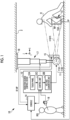
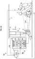
- an X-ray imaging system 10 that uses X-rays as radiation includes an X-ray source 11, a radiation source control device 12, an electronic cassette 13, a console 14, and an optical camera 15.
- an imaging support device is configured by the console 14 and the optical camera 15.
- the X-ray source 11 is an example of a radiation source.
- the electronic cassette 13 is an example of a radiation image detector.
- the electronic cassette 13 is disposed at a position facing the X-ray source 11.
- the electronic cassette 13 By disposing a subject H between the X-ray source 11 and the electronic cassette 13, it is possible to capture an X-ray image of an imaging site (knee in Fig. 1 ) of the subject H.
- the X-ray source 11 and the electronic cassette 13 configure an X-ray imaging apparatus.
- This X-ray imaging apparatus is an example of a radiography apparatus.
- the electronic cassette 13 may be disposed by using an imaging table.
- the radiologist hereinafter, simply referred to as a technician
- the technician RG positions the subject H, and then the technician RG performs an X-ray imaging operation.
- the X-ray source 11 includes an X-ray tube 11A that generates X-rays and an irradiation field limiter 11B that limits an irradiation field RF that is a region irradiated with X-rays.
- the X-ray source 11 may include an irradiation field display light source (not shown) that emits irradiation field display light indicating the irradiation field RF on an X-ray incident surface 13A of the electronic cassette 13.
- the X-ray tube 11A has a filament that emits thermions and a target that collides with the thermions emitted from the filament and emits X-rays.
- the irradiation field limiter 11B for example, by disposing four lead plates that shield X-rays on respective quadrangular sides, a quadrangular irradiation opening for transmitting X-rays is formed at the center. In this case, the irradiation field limiter 11B changes a size of the irradiation opening by moving positions of the lead plates, and sets the irradiation field RF.
- the radiation source control device 12 has a touch panel 12A, a voltage generation unit 12B, and a control unit 12C.
- the touch panel 12A is operated by the technician RG in a case where X-rays irradiation conditions and a size of the irradiation opening of the irradiation field limiter 11B are set.
- the X-ray irradiation conditions include a tube voltage and a tube current applied to the X-ray source 11, and the X-ray irradiation time.
- the voltage generation unit 12B generates a tube voltage applied to the X-ray tube 11A.
- the control unit 12C sets the tube voltage, the tube current, and the X-ray irradiation time to values set by using the touch panel 12A.
- the control unit 12C has a timer that starts clocking in a case where X-rays are generated from the X-ray tube 11A.
- the control unit 12C stops the operation of the X-ray tube 11A, for example, when the time measured by the timer reaches the irradiation time defined in the irradiation conditions.
- the control unit 12C operates the irradiation field limiter 11B, and sets the size of the irradiation opening to a size set by using the touch panel 12A.
- An irradiation switch 16 is connected to the control unit 12C via a cable or the like.
- the irradiation switch 16 is operated by the technician RG in a case where irradiation of X-rays is started.
- the radiation source control device 12 In a case where the irradiation switch 16 is operated, the radiation source control device 12 generates X-rays in the X-ray tube 11A. Consequently, X-rays are applied toward the irradiation field RF.
- the electronic cassette 13 detects an X-ray image XP based on X-rays emitted from the X-ray source 11 and transmitted through the imaging site of the subject H.
- the electronic cassette 13 has a wireless communication unit and a battery, and performs an operation wirelessly.
- the electronic cassette 13 wirelessly transmits the detected X-ray image XP to the console 14.
- the X-ray image XP is an example of a radiation image.
- the X-ray source 11 is suspended vertically downward from a ceiling 2 of an imaging room.
- the X-ray source 11 is held by a suspension holding mechanism 17.
- the suspension holding mechanism 17 is attached to the ceiling 2 via a horizontal movement mechanism 18.
- the suspension holding mechanism 17 holds the X-ray source 11 in a vertical direction ( ⁇ Z direction) to be able to be moved up and down.
- the horizontal movement mechanism 18 movably holds the suspension holding mechanism 17 in an X-ray irradiation axis direction ( ⁇ X direction) and a direction ( ⁇ Y direction) orthogonal to the X-ray irradiation axis direction of the X-ray source 11.
- a motor (not shown) is provided in each of the suspension holding mechanism 17 and the horizontal movement mechanism 18, and it is possible to move the X-ray source 11 manually or electrically in each direction. Operations of the suspension holding mechanism 17 and the horizontal movement mechanism 18 are controlled by the control unit 12C. Whether to move the X-ray source 11 manually or electrically may be selected by using the touch panel 12A. By moving the X-ray source 11, a position of the irradiation field RF can be adjusted.
- the optical camera 15 is an optical digital camera configured to include a complementary metal oxide semiconductor (CMOS) type image sensor or a charge coupled device (CCD) type image sensor, and performing imaging based on visible light as an example.
- CMOS complementary metal oxide semiconductor
- CCD charge coupled device
- the optical camera 15 enables still image imaging and motion picture imaging.
- An optical axis of the optical camera 15 is parallel to the irradiation axis of X-rays passing through the center of the irradiation field RF.
- the optical camera 15 images a region including the irradiation field RF and generates an optical image.
- the optical image is an image indicating the imaging site of the subject H located in the irradiation field RF.
- the optical image is, for example, a color still image or motion picture.
- the optical camera 15 is attached to an outer peripheral portion of the X-ray source 11.
- the optical camera 15 does not have to be attached to the outer peripheral portion of the X-ray source 11, or may be built in the X-ray source 11.
- an objective lens and an imaging element may be configured separately.
- the objective lens may be disposed on the outer peripheral portion of the X-ray source 11 and the imaging element may be built in a portion other than the X-ray source 11 (for example, an arm supporting the X-ray source 11).
- the optical camera 15 is connected to the console 14 by wire or wirelessly.
- the console 14 functions as an imaging control device to control an imaging operation of the optical camera 15.
- the console 14 causes the optical camera 15 to capture a still image in conjunction with X-ray imaging, and also to capture a motion picture during an imaging preparation period before the start of the X-ray imaging.
- the console 14 is installed in an operation room adjacent to the imaging room in which the X-ray source 11 is installed.
- the console 14 transmits a still image capturing command signal to the optical camera 15 in a case where the irradiation switch 16 is operated.
- the optical camera 15 captures a still image of a region including the irradiation field RF in response to the still image capturing command signal input from the console 14.
- An optical image (hereinafter referred to as a still image SP) obtained through this still image capturing is transmitted to the console 14.
- the console 14 transmits a motion picture capturing start signal to the optical camera 15 in a case where an operation of starting imaging preparation is performed by the technician RG.
- the optical camera 15 starts to capture a motion picture of a region including the irradiation field RF in response to the motion picture capturing start signal input from the console 14.
- An optical image (hereinafter referred to as a motion picture MP) obtained through this motion picture capturing is transmitted to the console 14 as a so-called live view image in real time at the time of motion picture capturing.
- the electronic cassette 13 includes a sensor panel 20, a circuit unit 21, and a rectangular parallelepiped-shaped portable casing 22 that accommodates the sensor panel 20.
- the casing 22 has a size conforming to the international standard International Organization for Standardization (ISO) 4090:2001, which is substantially the same as that of, for example, a film cassette, an imaging plate (IP) cassette, or a computed radiography (CR) cassette.
- ISO International Organization for Standardization
- the electronic cassette 13 is positioned in a posture in which the X-ray incident surface 13A that is an upper surface of the casing 22 faces the X-ray source 11, and the X-ray incident surface 13A is irradiated with X-rays.
- the casing 22 is also provided with a switch for switching between turning-on and turning-off of a main power source, and an indicator for reporting an operation state of the electronic cassette 13 such as a remaining battery usage time or an imaging ready state.
- the sensor panel 20 is configured with a scintillator 20A and a light detection substrate 20B.
- the scintillator 20A and the light detection substrate 20B are laminated in the order of the scintillator 20A and the light detection substrate 20B when viewed from the X-ray incident surface 13A side.
- the scintillator 20A has phosphors such as CsI: Tl (thallium-activated cesium iodide) or GOS (Gd 2 O 2 S: Tb, terbium-activated gadolinium oxysulfide), and converts X-rays incident via the X-ray incident surface 13A into visible light and emits the visible light.
- a sensor panel in which the light detection substrate 20B and the scintillator 20A are laminated in this order when viewed from the X-ray incident surface 13A side may be used.
- a direct conversion type sensor panel that directly converts X-rays into signal charge with a photoconductor such as amorphous selenium may be used.
- the light detection substrate 20B detects the visible light emitted from the scintillator 20A and converts the visible light into electric charge.
- the circuit unit 21 controls the drive of the light detection substrate 20B and generates the X-ray image XP on the basis of the electric charge output from the light detection substrate 20B.
- a plurality of pixels are arranged in a two-dimensional matrix on the light detection substrate 20B.
- Each pixel photoelectrically converts the visible light emitted by the scintillator 20A to generate and store electric charge.
- the X-ray image XP is generated by converting the electric charge stored in each pixel into a digital signal in the circuit unit 21.
- the electronic cassette 13 has a function of detecting, for example, the start of X-ray irradiation.
- This irradiation start detection function is realized by, for example, an irradiation start detection sensor provided on the light detection substrate 20B.
- the irradiation start detection sensor is configured with, for example, some of a plurality of pixels disposed in a two-dimensional matrix. In a case where a dose signal periodically output from the irradiation start detection sensor exceeds a threshold value, it is determined that the X-ray irradiation has started.
- the electronic cassette 13 has a timer that starts clocking when the start of X-ray irradiation is detected, in the same manner as the radiation source control device 12.
- the electronic cassette 13 determines that the X-ray irradiation is finished when the time measured by the timer reaches the irradiation time included in the irradiation conditions set for the console 14. Thereby, the electronic cassette 13 can detect the X-ray image XP based on the applied X-ray by performing the X-ray detection operation only for a period corresponding to the irradiation time included in the irradiation conditions.
- the electronic cassette 13 has an image memory and a wireless communication circuit.
- the electronic cassette 13 stores the X-ray image XP generated by the circuit unit 21 in the image memory, and transmits the X-ray image XP stored in the image memory to the console 14 with the wireless communication circuit.
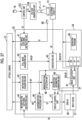
- the console 14 includes a display 30, an input device 31, a central processing unit (CPU) 32, a storage device 34, a memory 33, and a communication unit 35. These constituents are connected to each other via a data bus 36.
- CPU central processing unit
- the display 30 is a display unit that displays various operation screens provided with operation functions by a graphical user interface (GUI), the X-ray image XP, and the optical images (the still image SP and the motion picture MP).
- the input device 31 is an input operation unit including a touch panel, a keyboard, and the like.
- the storage device 34 is, for example, a hard disk drive (HDD) array, which is built in the console 14 or externally connected to the console 14. External connection is made via a cables or a network.
- the storage device 34 stores control programs such as an operating system, various application programs, and various types of data associated with these programs.
- the memory 33 is a work memory for the CPU 32 to execute a process.
- the CPU 32 collectively controls each unit of the console 14 by loading the program stored in the storage device 34 to the memory 33 and executing processes according to the program.
- the communication unit 35 transmits and receives various types of data such as the X-ray image XP and the optical images (the still image SP and the motion picture MP) to and from the electronic cassette 13 and the optical camera 15.
- the communication unit 35 communicates with the control unit 12C of the radiation source control device 12.
- the console 14 receives input of an imaging order 37 shown in Fig. 4 .
- the imaging order 37 is information for instructing the technician RG to perform X-ray imaging, for example, from an imaging requester in a clinical department.
- the imaging order 37 is delivered to the console 14 from, for example, a radiology information system (RIS) (not shown).
- RIS radiology information system
- the imaging order 37 has items such as an order identification data (ID), a subject ID, and an imaging technique.
- ID is a symbol or number that identifies each imaging order 37, and is automatically assigned by the RIS.
- subject ID a subject ID of the subject H who is an imaging target is written.
- subject ID is a symbol or a number that identifies each subject H.
- the imaging technique is information regarding an imaging site of the subject H and a posture and an orientation of the imaging site.
- the imaging site includes the head, the cervical spine, the chest, the abdomen, hands, fingers, elbows, and the like.
- the posture is a posture of the subject H such as a standing posture, a lying posture, or a sitting posture.
- the orientation is an orientation of the subject H with respect to the X-ray source 11, such as the front, the side, or the back.
- the imaging order 37 includes items of subject information such as the name, gender, age, height, and weight of the subject H.
- a condition table 38 shown in Fig. 5 is stored in the storage device 34 of the console 14. Irradiation conditions corresponding to each imaging technique are associated and registered in the condition table 38.
- the console 14 displays an imaging order list that lists the details of the imaging order 37 shown in Fig. 4 on the display 30 through an operation of the technician RG.
- the technician RG may view the imaging order list and check the details of the imaging order 37.
- the console 14 displays the details of the condition table 38 shown in Fig. 5 on the display 30.
- the technician RG may select and set irradiation conditions that match the imaging technique designated in the imaging order 37.
- the console 14 wirelessly transmits condition setting signals including various types of information such as irradiation conditions set by the technician RG, an order ID, and a console ID as console identification information to the electronic cassette 13.
- the console 14 stores the X-ray image XP received from the electronic cassette 13 in the storage device 34 that is a storage unit, for example, as an image file in a format conforming to the Digital Imaging and Communication in Medicine (DICOM) standard.
- the image file the X-ray image XP and accessory information are associated with each other by one image ID.
- the accessory information includes an order ID, a subject ID, an imaging technique, irradiation conditions, and the like.
- the still image SP obtained by the optical camera 15 capturing a still image in conjunction with the X-ray imaging is added with an image ID (optical image ID) associated with an image ID (X-ray image ID) of the X-ray image XP obtained through the X-ray imaging.
- image ID optical image ID
- X-ray image ID image ID of the X-ray image XP obtained through the X-ray imaging.
- the X-ray image XP and the still image SP obtained when X-ray imaging is performed once are stored in the storage device 34 in association with the X-ray image ID and the optical image ID.
- a doctor makes a diagnosis of the joint cavity JC of the knee on the basis of the X-ray image XP. Therefore, it is necessary that the joint cavity JC is clearly depicted in the X-ray image XP.
- the storage device 34 stores an operation program 40.
- the condition table 38 shown in Fig. 5 is also stored in the storage device 34.
- a plurality of functional units are configured in the CPU 32 by executing the operation program 40.
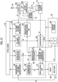
- the operation program 40 uses the CPU 32 as a still image capturing instruction unit 41, a still image acquisition unit 42, an association unit 43, a motion picture capturing instruction unit 44, a motion picture acquisition unit 45, a superimposition processing unit 46, a display control unit 47, and a misregistration detection unit 48, and a notification information generation unit 49.
- the still image capturing instruction unit 41 receives an X-ray irradiation start signal ES generated by the control unit 12C of the radiation source control device 12 and supplied to the voltage generation unit 12B in response to pressing of the irradiation switch 16. Upon receiving the X-ray irradiation start signal ES, the still image capturing instruction unit 41 instructs the optical camera 15 to execute still image capturing.
- the still image acquisition unit 42 acquires the still image SP generated by the optical camera 15 capturing a still image.
- the still image SP acquired by the still image acquisition unit 42 is input to the association unit 43.
- the association unit 43 receives the X-ray image XP detected by the electronic cassette 13 on the basis of the X-rays emitted from the X-ray source 11 via the communication unit 35 in response to pressing of the irradiation switch 16.
- the association unit 43 stores the still image SP input to the still image acquisition unit 42 and the X-ray image XP input from the electronic cassette 13 in the storage device 34 as shown in Fig. 6 in association with each other.
- the motion picture capturing instruction unit 44 transmits a motion picture capturing start signal for instructing the optical camera 15 to start motion picture capturing in response to input of a reimaging preparation start signal RS from the input device 31.
- the technician RG checks the X-ray image XP acquired through X-ray imaging, and in a case where it is determined that there is imaging failure, the technician RG operates the input device 31 to cause the imaging support device to transition to a reimaging preparation mode. In a case where the imaging technique is "knee/bending posture/side", the technician RG determines that there is imaging failure in a case where, for example, the joint cavity JC of the knee is not clearly depicted in the X-ray image XP.
- the motion picture acquisition unit 45 acquires, in real time for each frame, the motion picture MP generated by the optical camera 15 capturing a motion picture.
- the motion picture MP acquired by the motion picture acquisition unit 45 is input to the superimposition processing unit 46 for each frame.
- the superimposition processing unit 46 acquires the still image SP stored in the storage device 34, and superimposes the still image SP on each frame of the motion picture MP as shown in Fig. 8 .
- the superimposition processing unit 46 inputs a superimposition image TP generated by superimposing the motion picture MP and the still image SP to the display control unit 47 for each frame.
- the display control unit 47 displays the superimposition image TP on the display 30 for each frame. That is, the display control unit 47 superimposes the still image SP on the motion picture MP and displays it on the display 30 in real time.
- the still image SP in the superimposition image TP is associated with the X-ray image XP in which the technician RG has determined that there is imaging failure, and is an example of a first optical image indicating a position of the subject H at the time of imaging failure.
- the motion picture MP in the superimposition image TP is an example of a second optical image indicating the current position of the subject H during reimaging preparation. Therefore, the technician RG can check the current position of the subject H with respect to the time of imaging failure by checking the superimposition image TP displayed in real time on the display 30.
- the motion picture capturing of the optical camera 15 is finished in response to receiving an execution instruction for still image capturing from the still image capturing instruction unit 41 described above.
- the still image acquisition unit 42 may acquire one frame of the motion picture MP as the still image SP.
- the misregistration detection unit 48 operates during a period in which the optical camera 15 is performing motion picture capturing.
- the motion picture MP acquired by the motion picture acquisition unit 45 is input to the misregistration detection unit 48 for each frame.
- the misregistration detection unit 48 acquires the still image SP stored in the storage device 34, and as shown in Fig. 9 , performs image processing to detect a misregistration amount of the subject H between each frame of the motion picture MP and the still image SP.
- the misregistration detection unit 48 detects a misregistration amount by obtaining a movement vector by using, for example, a block matching method.
- the misregistration detection unit 48 may detect a misregistration amount according to a machine learning method using a neural network.
- the misregistration detection unit 48 may detect a misregistration amount by extracting feature amounts of the motion picture MP and the still image SP by using a convolutional neural network.
- the neural network by learning various images of the subject H as training data, it is possible to accurately detect a misregistration due to rotation, turning, and the like without limitation to a case where the subject H moves in parallel.
- the notification information generation unit 49 generates, as notification information, a direction (vector) in which the current position of the subject H indicated by the motion picture MP is moved to the position of the subject H at the time of imaging failure indicated by the still image SP, on the basis of the misregistration amount detected by the misregistration detection unit 48.
- This notification information is input to the display control unit 47.
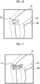
- the display control unit 47 generates an arrow 50 indicating a direction included in the notification information, and displays the arrow 50 on the display 30 in a state in which the arrow is combined on the superimposition image TP as shown in Fig. 10 , for example.
- a direction and a size of the arrow 50 displayed on the display 30 are changed depending on movement of the subject H. For example, a size of the arrow 50 becomes smaller as a misregistration amount detected by the misregistration detection unit 48 is reduced.
- the technician RG can position the subject H to the position at the time of imaging failure indicated by the still image SP by giving an instruction to the subject H with voice or the like and guiding a position of the subject H in a direction in which the arrow 50 becomes smaller on the basis of the arrow 50 or the like displayed on the display 30.
- the technician RG can position the subject H to the position at the time of imaging failure and finely adjust the position of the subject H with this position as a reference even in a case where the subject H moves significantly from the time of the imaging failure.
- a microphone may be provided in the operation room and a speaker may be provided in the imaging room.
- the technician RG can easily give an instruction for positioning to the subject H in the imaging room from the operation room.
- the notification information generation unit 49 may generate notification information indicating a direction of the rotation or the turning.
- Fig. 11 shows an example in which an arrow 51 indicating that the knee of the subject H should be turned inward in order to move the position of the subject H to the position at the time of imaging failure is displayed on the superimposition image TP.
- the internal turning is an operation in which the subject H turns the knee inward.
- the technician RG checks details of the imaging order 37 on the display 30, and sets irradiation conditions by using the input device 31 and the touch panel 12A.
- the technician RG positions the X-ray source 11, the electronic cassette 13, and the subject H according to an imaging technique included in the imaging order 37.
- the imaging technique is "knee/bending posture/side”.
- the technician RG bends one leg of the subject H and positions the subject H such that the side of the knee faces the X-ray incident surface 13 A of the electronic cassette 13 and the knee is located at the center of the irradiation field RF (refer to Fig. 1 ).
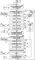
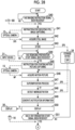
- the still image capturing instruction unit 41 determines whether or not the X-ray irradiation start signal ES has been received from the control unit 12C of the radiation source control device 12 (step S10).
- the X-ray irradiation start signal ES is generated by the control unit 12C of the radiation source control device 12 in response to the technician RG pressing the irradiation switch 16 after positioning the subject H.
- the X-ray irradiation start signal ES generated by the control unit 12C is supplied to the voltage generation unit 12B and the console 14.
- the voltage generation unit 12B irradiates the subject H with X-rays from the X-ray source 11 in response to the X-ray irradiation start signal ES.
- the electronic cassette 13 detects the X-ray image XP of the subject H on the basis of the X-rays transmitted through the subject H.
- the still image capturing instruction unit 41 instructs the optical camera 15 to execute still image capturing (step S11).
- the still image acquisition unit 42 acquires the still image SP generated by the optical camera 15 capturing a still image (step S12).
- the console 14 acquires the X-ray image XP detected by the electronic cassette 13 (step S13).
- the association unit 43 stores the acquired X-ray image XP and the still image SP in the storage device 34 in association with each other (step S14).
- the display control unit 47 displays the X-ray image XP stored in the storage device 34 on the display 30 (step S15).
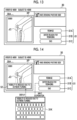
- Fig. 13 shows an example of a screen of the display 30 on which the X-ray image XP is displayed. As shown in Fig. 13 , the X-ray image XP is displayed on the display 30 in a image display region 30A.
- the display 30 displays a first operation button 31A for performing reimaging, a second operation button 31B for inputting a reason for imaging failure, a third operation button 31C for performing an end operation, and the like.
- the first operation button 31A, the second operation button 31B, and the third operation button 31C configure an input device 31 and are operated by a touch panel formed on the screen of the display 30.
- the technician RG checks the X-ray image XP displayed in the image display region 30A and determines that the image is favorable, the technician RG finishes the process related to the X-ray imaging by pressing the third operation button 31C.
- the technician RG can enter a reason for the imaging failure by using a keyboard 31K shown in Fig. 14 by pressing the second operation button 31B.
- An input reason for imaging failure 52 is displayed in the image display region 30A by the display control unit 47.
- the keyboard 31K is, for example, a virtual keyboard, and is operably displayed on the screen of the display 30 by the touch panel.
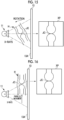
- the X-ray image XP shown in Figs. 13 and 14 is an example in which the bones of the joint overlap with each other on the X-ray optical path due to outward turning of the knee, and thus the visibility of the joint cavity JC is reduced.
- Fig. 15 schematically shows a state in which the visibility of the joint cavity JC is reduced in the X-ray image XP due to rotation of the knee.
- Fig. 16 schematically shows a state in which the visibility of the joint cavity JC is reduced in the X-ray image XP due to parallel movement of the knee. Since the X-rays applied to the subject H are a flux of light that radially diverges from a focal point of the X-ray source 11, a misregistration occurs in the subject H due to turning, rotation, or parallel movement, and thus an incidence angle of the X-rays with respect to the subject H changes such that the visibility of the joint cavity JC decreases. In reality, the joint cavity JC is narrow, and the knee misregistration occurs due to a combination of turning, rotation, parallel movement, and the like. Therefore, even a slight misregistration reduces the visibility of the joint cavity JC.
- the technician RG presses the first operation button 31A in a case of performing reimaging (refer to Fig. 13 ).
- the input device 31 In a case where the first operation button 31A is pressed, the input device 31 generates the reimaging preparation start signal RS and transmits the signal to the motion picture capturing instruction unit 44.
- step S15 it is determined whether or not the end operation has been performed by the technician RG pressing the third operation button 31C (step S16). In a case where it is determined that the end operation has been performed (step S16: YES), the process ends.
- step S16 determines whether or not the motion picture capturing instruction unit 44 has received the reimaging preparation start signal RS from the input device 31 (step S17).
- step S17 determines whether or not the motion picture capturing instruction unit 44 has received the reimaging preparation start signal RS from the input device 31 (step S17).
- step S18 the motion picture capturing instruction unit 44 transmits a motion picture capturing start signal to the optical camera 15 (step S18).
- the motion picture acquisition unit 45 acquires the motion picture MP generated by the optical camera 15 capturing a motion picture for each frame (step S19).
- the superimposition processing unit 46 acquires the still image SP stored in the storage device 34, performs a process of superimposing the still image SP on the frame of the motion picture MP acquired by the motion picture acquisition unit 45, and generates the superposition image TP (step S20).
- the misregistration detection unit 48 acquires the still image SP stored in the storage device 34, and detects a misregistration amount of the subject H between the frame of the motion picture MP acquired by the motion picture acquisition unit 45 and the still image SP (step S21).
- the notification information generation unit 49 generates notification information indicating a direction (vector) in which the current position of the subject H is moved to the position of the subject H at the time of imaging failure, on the basis of the misregistration amount detected by the position deviation detection unit 48 (step S22).
- the display control unit 47 generates an arrow (for example, the arrow 50 shown in Fig. 10 ) indicating the direction included in the notification information, and displays the arrow on the display 30 in a state in which the arrow is combined on the superimposition image TP (step S23). Thereafter, in the same manner as in step S10, it is determined whether or not the still image capturing instruction unit 41 has received the X-ray irradiation start signal ES from the control unit 12C (step S24).
- an arrow for example, the arrow 50 shown in Fig. 10
- step S24 While the still image capturing instruction unit 41 does not receive the X-ray irradiation start signal ES (step S24: NO), the process returns to step S19, and the motion picture acquisition unit 45 acquires the next frame of the motion picture MP. Until the X-ray irradiation start signal ES is received, the processes in steps S19 to S24 are repeatedly executed. Consequently, the superimposition image TP in which the still image SP is superimposed on the motion picture MP is displayed on the display 30 in real time.
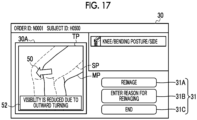
- Fig. 17 shows an example of a screen of the display 30 on which the superimposition image TP is displayed.
- the superimposition image TP is displayed on the display 30 in the image display region 30A.
- the arrow 50 and the reason for imaging failure 52 are combined and displayed on the superimposition image TP.
- the technician RG can check whether or not the position of the subject H has moved from the time of the imaging failure on the basis of the superimposition image TP.
- the technician RG gives an instruction to the subject H with voice or the like on the basis of the arrow 50 or the like, and thus temporarily determines the current position of the subject H (the position indicated by the motion picture MP) to the position at the time of imaging failure (the position indicated by the still image SP).
- the technician RG can finely adjust the position of the subject H such that the imaging failure does not occur at the time of reimaging by referring to the reason for imaging failure 52.
- the X-ray image XP may be displayed on the display 30 in addition to the superimposition image TP.
- the technician RG can finely adjust the position of the subject H by referring to the X-ray image XP in addition to the reason for imaging failure 52. After that, in a case where the fine adjustment of the position of the subject H is completed, the technician RG presses the irradiation switch 16 to execute the reimaging.
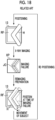
- the effect of the imaging support device having the above configuration will be described with reference to Figs. 18 and 19 .
- the joint cavity JC needs to be clearly depicted in the X-ray image XP, but since X-rays are a flux of light that radially diverges from the focal point of the X-ray source 11, an incidence angle of X-rays changes due to a slight misregistration of the joint, and the depiction of the joint cavity JC becomes unclear.
- there is imaging failure and reimaging is required.
- the technician RG can easily ascertain the position of the subject H at the time of imaging failure. Therefore, the technician RG can position the subject H to the position at the time of imaging failure and then finely adjust the position of the subject H from the position at the time of imaging failure on the basis of a reason for the imaging failure or the like.
- the favorable X-ray image XP can be obtained by finely adjusting the position of the subject H and then performing reimaging. As described above, according to the technique of the present disclosure, it is possible to suppress the repetition of reimaging. As a result, unnecessary exposure to the subject H can be suppressed and the examination time can be reduced.
- the superimposition image TP in which the optical image (still image SP) acquired in conjunction with the X-ray imaging and the current optical image (motion picture MP) of the subject H are superimposed is displayed in real time. Even though the subject H moves significantly from the time of the imaging failure, the technician RG can more easily ascertain the position of the subject H at the time of imaging failure on the basis of the still image SP in the superimposition image TP.
- the display 30 that provides a notification of notification information generated by the notification information generation unit 49 is used as a notification unit, and a direction in which the current position of the subject H is moved to the position of the subject H at the time of imaging failure is indicated by an arrow.
- This notification information may be text or may be an arrow added with text.
- the notification information may be reported with voice by using a speaker as a notification unit.
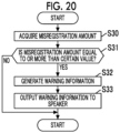
- the notification information generation unit 49 may generate warning information for giving a warning to the technician RG in a case where a misregistration amount detected by the misregistration detection unit 48 is equal to or more than a certain value.
- the notification information generation unit 49 performs a process shown in Fig. 20 in parallel to the notification information generation process (step S22) described in the above embodiment.
- the notification information generation unit 49 acquires a misregistration amount (for example, a magnitude of a vector representing a direction) from the misregistration detection unit 48 (step S30), and determines whether or not the acquired misregistration amount is equal to or more than a certain value (step S31).
- the notification information generation unit 49 In a case where the misregistration amount is equal to or more than the certain value (step S31: YES), the notification information generation unit 49 generates warning information (step S32), and outputs the generated warning information from a speaker as a notification unit (step S33).
- the notification unit for reporting the warning information is not limited to a speaker, and may be any one that stimulates perception (auditory, visual, or the like) of the technician RG.
- the display 30 may be used as a notification unit, and a message indicating a warning may be displayed on a screen thereof.
- the reason for imaging failure can be entered by the technician RG using the keyboard 31K or the like, but the CPU 32 may be configured to automatically determine the reason for imaging failure from the X-ray image XP through a machine learning method using a neural network.
- the neural network learns data in which the X-ray image XP in which imaging failure has occurred is associated with the reason for the imaging failure as training data, and can thus determine reasons for imaging failure such as outward turning, inward turning, and angles thereof for the new X-ray image XP in which the imaging failure has occurred.
- a position of the subject H is moved to the position at the time of imaging failure by the technician RG on the basis of the arrow 50 displayed on the superimposition image TP.
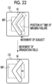
- a relative position of the subject H with respect to the irradiation field RF may be moved to the position at the time of imaging failure by moving the irradiation field RF of X-rays without changing the position of the subject H.
- an irradiation field movement control unit 60 that controls movement of the irradiation field RF is added to the CPU 32 of the console 14.
- the irradiation field movement control unit 60 controls a movement mechanism 19 that moves the X-ray source 11 via the control unit 12C of the radiation source control device 12 on the basis of a misregistration amount detected by the misregistration detection unit 48.
- the movement mechanism 19 is configured with the above suspension holding mechanism 17 and the horizontal movement mechanism 18. As shown in Fig.
- the irradiation field movement control unit 60 moves the irradiation field RF in a direction in which a misregistration amount detected by the misregistration detection unit 48 decreases, and thus a relative position of the subject H with respect to the irradiation field RF is moved to the position at the time of imaging failure.
- the electronic cassette 13 is fixed, but in a case where the electronic cassette 13 is configured to be movable in conjunction with movement of the X-ray source 11, the electronic cassette 13 may be moved in correlation with movement of the irradiation field RF.
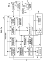
- an X-ray imaging system 10A according to the second embodiment includes a projector 70 in addition to the configuration of the X-ray imaging system 10 according to the first embodiment.
- an imaging support device is configured by the CPU 32, the optical camera 15, and the projector 70.
- the projector 70 is attached to the outer peripheral portion of the X-ray source 11.
- the projector 70 is, for example, a small laser projector, and is disposed to project a projection image toward the X-ray incident surface 13A of the electronic cassette 13.
- a projection image generation unit 71 that generates a projection image to be supplied to the projector 70 is added to the CPU 32 of the console 14.
- the projection image generation unit 71 acquires the still image SP captured by the optical camera 15 and stored in the storage device 34 in association with the X-ray image XP by the association unit 43, and generates a projection image.
- the projection image generation unit 71 supplies the generated projection image to the projector 70, and causes the projector 70 to project the projection image toward the electronic cassette 13.
- the projection image generation unit 71 performs projection in a state in which the subject H is located between the X-ray source 11 and the electronic cassette 13 during a reimaging preparation period in which the superimposition image TP is displayed on the display 30.
- Other configurations of the X-ray imaging system 10A are the same as the configurations of the X-ray imaging system 10 according to the first embodiment.
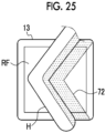
- Fig. 25 exemplifies a projection image 72 projected onto the electronic cassette 13 by the projector 70.
- the projection image 72 is an image indicating the subject H at the time of imaging failure, and a part of the projection image 72 is projected on the surface of the subject H.
- the technician RG can move a position of the subject H to the position at the time of imaging failure by adjusting the position of the subject H such that the subject H overlaps the projection image 72 in a case of preparing for reimaging.
- an X-ray imaging system 10B includes a remote controller 80 that causes the optical camera 15 to capture a still image in addition to the configuration of the X-ray imaging system 10 according to the first embodiment.
- an imaging support device is configured by the CPU 32, the optical camera 15, and the remote controller 80.
- the console 14 receives the imaging command signal IS from the remote controller 80 via the communication unit 35.
- the optical camera 15 may be provided with a receiving unit for the imaging command signal IS transmitted from the remote controller 80.
- the superimposition processing unit 46 acquires the image (the still image SP0 or the still image SP) selected by the image selection unit 81, superimposes the acquired image on each frame of the motion picture MP, and generates the superimposition image TP.
- the misregistration detection unit 48 acquires the image (the still image SP0 or the still image SP) selected by the image selection unit 81, and detects a misregistration amount of the subject H between the acquired image and each frame of the motion picture MP.
- Other configurations of the X-ray imaging system 10B are the same as the configurations of the X-ray imaging system 10 according to the first embodiment.
- the technician RG positions the subject H with respect to the X-ray source 11 and the electronic cassette 13 (refer to Fig. 26 ).
- the technician RG instructs the optical camera 15 to execute still image capturing by operating the remote controller 80 in a state in which the subject H is positioned to a desired position.
- the technician RG operates the input device 31 to start preparing for X-ray imaging.
- the motion picture capturing instruction unit 44 transmits a motion picture capturing start signal to the optical camera 15 (step S45).
- the motion picture acquisition unit 45 acquires the motion picture MP generated by the optical camera 15 capturing a motion picture for each frame (step S46).
- the superimposition processing unit 46 acquires an image stored in the storage device 34.
- the still image SP0 is selected by the image selection unit 81.
- the superimposition processing unit 46 acquires the still image SP0 via the image selection unit 81, performs a process of superimposing the still image SP0 on the frame of the motion picture MP acquired by the motion picture acquisition unit 45, and generates the superposition image TP (step S47).
- the misregistration detection unit 48 acquires the still image SP0 stored in the storage device 34 via the image selection unit 81, and detects a misregistration amount of the subject H between the frame of the motion picture MP acquired by the motion picture acquisition unit 45 and the still image SP0 (step S48).
- the notification information generation unit 49 generates notification information indicating a direction (vector) in which the current position of the subject H is moved to the position of the subject H at the time of initial positioning on the basis of the misregistration amount detected by the misregistration detection unit 48 (step S49).
- the display control unit 47 generates an arrow indicating the direction included in the notification information, and displays the arrow on the display 30 in a state in which the arrow is combined on the superimposition image TP (step S50). Thereafter, similarly to step S10 shown in Fig. 12 in the first embodiment, it is determined whether or not the still image capturing instruction unit 41 has received the X-ray irradiation start signal ES from the control unit 12C (step S51).
- step S51 NO
- the process returns to step S46, and the motion picture acquisition unit 45 acquires the next frame of the motion picture MP.
- the processes in steps S46 to S51 are repeatedly executed. Consequently, the superimposition image TP in which the still image SP0 is superimposed on the motion picture MP is displayed on the display 30 in real time.
- the superimposition image TP displayed on the display 30 is the same as the superimposition image TP shown in Fig. 17 in the first embodiment.
- the technician RG can check whether or not the position of the subject H has been moved from the time of initial positioning on the basis of the superimposition image TP. In a case where the subject H has moved, the technician RG gives an instruction to the subject H with voice or the like on the basis of an arrow or the like displayed on the superimposition image TP, and thus the current position of the subject H (indicated by the motion picture MP) is moved to the position at the time of positioning (the position indicated by the still image SP0).
- the still image capturing instruction unit 41 In a case where the technician RG presses the irradiation switch 16 and thus the still image capturing instruction unit 41 receives the X-ray irradiation start signal ES (step S51: YES), the still image capturing instruction unit 41 instructs the optical camera 15 to execute still image capturing (step S52). Since the processes in steps S52 to S65 are the same as the processes in steps S11 to S24 shown in Fig. 12 in the first embodiment, the description thereof will be omitted.
- the X-ray image XP and the still image SP captured in conjunction with the X-ray imaging are stored in the storage device 34 in association with the still image SP0.
- an image (the still image SP0 or the still image SP) to be superimposed on the motion picture MP when preparing for reimaging.
- a fourth operation button 31D for switching between images is displayed.
- the technician RG can switch an image to be superimposed on the motion picture MP between the still image SP0 acquired at the time of initial positioning and the still image SP acquired at the time of imaging failure. Consequently, the technician RG can also move the position of the subject H to the position of the subject H at the time of initial positioning and perform reimaging.
- the technician RG can determine whether imaging failure has occurred due to movement of the subject H from initial positioning or the imaging failure has occurred despite the subject H not having moved since initial positioning.
- the optical camera 15 may be attached to a location other than the X-ray source 11, such as a wall or a ceiling of the imaging room, as long as the subject H located in the irradiation field RF can be imaged.
- the optical camera 15 is not limited to visible light, and may be any camera that optically performs imaging.
- the optical camera 15 may be an infrared camera that performs imaging on the basis of infrared rays.
- the projector 70 may be attached to a location other than the X-ray source 11, such as a wall or a ceiling of the imaging room, as long as an image can be projected to the irradiation field RF.
- hardware structures of processing units executing various processes such as the still image capturing instruction unit 41, the still image acquisition unit 42, the association unit 43, the motion picture capturing instruction unit 44, the motion picture acquisition unit 45, the superimposition processing unit 46, the display control unit 47, and the misregistration detection unit 48, the notification information generation unit 49, the irradiation field movement control unit 60, the projection image generation unit 71, and the image selection unit 81 are various processors as described below.
- the various processors include a CPU, a programmable logic device (PLD), a dedicated electric circuit, and the like.
- the CPU is a general-purpose processor that executes software (program) and functions as various processing units.
- the PLD is a processor such as a field programmable gate array (FPGA) of which a circuit configuration can be changed after manufacturing.
- the dedicated electric circuit is a processor having a circuit configuration specially designed for executing a specific process, such as an application specific integrated circuit (ASIC).
- One processing unit may be configured with one of these various processors, or may be configured with a combination of two or more processors of the same type or different types (for example, a plurality of FPGAs or a combination of a CPU and an FPGA).
- a plurality of processing units may be configured by one processor.
- configuring a plurality of processing units with one processor first, there is a form in which one processor is configured by a combination of one or more CPUs and software, as typified by a computer used for a client or a server, and this processor functions as a plurality of processing units.
- SoC system on chip
- a processor that realizes functions of the entire system including a plurality of processing units with one integrated circuit (IC) chip is used.
- IC integrated circuit
- the various processing units are configured by using one or more of the above various processors as a hardware structure.
- the hardware structure of these various processors is, more specifically, an electric circuit (circuitry) in which circuit elements such as semiconductor elements are combined.
Landscapes
- Health & Medical Sciences (AREA)
- Life Sciences & Earth Sciences (AREA)
- Engineering & Computer Science (AREA)
- Medical Informatics (AREA)
- Physics & Mathematics (AREA)
- Public Health (AREA)
- General Health & Medical Sciences (AREA)
- Surgery (AREA)
- Biophysics (AREA)
- Veterinary Medicine (AREA)
- Pathology (AREA)
- Animal Behavior & Ethology (AREA)
- Biomedical Technology (AREA)
- Heart & Thoracic Surgery (AREA)
- Molecular Biology (AREA)
- Nuclear Medicine, Radiotherapy & Molecular Imaging (AREA)
- Radiology & Medical Imaging (AREA)
- Optics & Photonics (AREA)
- High Energy & Nuclear Physics (AREA)
- Dentistry (AREA)
- Orthopedic Medicine & Surgery (AREA)
- Oral & Maxillofacial Surgery (AREA)
- Computer Vision & Pattern Recognition (AREA)
- Physical Education & Sports Medicine (AREA)
- Rheumatology (AREA)
- Human Computer Interaction (AREA)
- Theoretical Computer Science (AREA)
- General Physics & Mathematics (AREA)
- Epidemiology (AREA)
- Primary Health Care (AREA)
- Apparatus For Radiation Diagnosis (AREA)
- Studio Devices (AREA)
- Closed-Circuit Television Systems (AREA)
Claims (10)
- Bildgebungsunterstützungsvorrichtung, die in einer Röntgenvorrichtung, die eine Strahlungsquelle (11) und einen Strahlungsbild-Detektor, der ein Strahlungsbild eines Motivs auf der Grundlage von Strahlung, die von der Strahlungsquelle emittiert wird und über das Motiv transmittiert wird, detektiert, enthält, verwendet wird, wobei die Bildgebungsunterstützungsvorrichtung umfasst:eine optische Kamera (15), die einen Bereich, der ein Bestrahlungsfeld der auf das Motiv angewendeten Strahlung von der Strahlungsquelle enthält, optisch abbildet; undmindestens einen Prozessor (32), wobeider Prozessorals ein erstes optisches Bild ein optisches Bild, das das Motiv in dem Bereich angibt, erfasst, indem die optische Kamera veranlasst wird, Bildgebung in Verbindung mit von der Röntgenvorrichtung durchgeführter Röntgenaufnahme durchzuführen, undein Strahlungsbild, das durch die Röntgenaufnahme erfasst wird, und das erste optische Bild in einer Speichereinheit in Verbindung miteinander speichert;als ein zweites optisches Bild ein optisches Bild, das das Motiv in dem Bereich angibt, erfasst, indem die optische Kamera veranlasst wird, Bildgebung durchzuführen, nachdem die Röntgenaufnahme durchgeführt wurde, undein Überlagerungsbild, in dem das erste optische Bild und das zweite optische Bild überlagert sind, und das Strahlungsbild auf einer Anzeigeeinheit anzeigt.
- Bildgebungsunterstützungsvorrichtung nach Anspruch 1,wobei das erste optische Bild ein Standbild ist und das zweite optische Bild ein Film ist, undder Prozessor das zweite optische Bild dem ersten optischen Bild überlagert und das Überlagerungsergebnis auf der Anzeigeeinheit in Echtzeit anzeigt.
- Bildgebungsunterstützungsvorrichtung nach Anspruch 1 oder 2,wobei der Prozessoreinen Fehlanpassungsbetrag des Motivs zwischen dem ersten optischen Bild und dem zweiten optischen Bild durch Bildverarbeitung detektiert, undeine Benachrichtigungseinheit mit Informationen in Bezug auf den Fehlanpassungsbetrag eine Benachrichtigungseinheit versorgt.
- Bildgebungsunterstützungsvorrichtung nach Anspruch 3,wobei die Benachrichtigungseinheit die Anzeigeeinheit (30) ist, undder Prozessor auf der Anzeigeeinheit eine Richtung, in der eine Position des Motivs zu einer Position, die durch das erste optische Bild angegeben wird, bewegt wird, auf der Grundlage des Fehlanpassungsbetrags anzeigt.
- Bildgebungsunterstützungsvorrichtung nach Anspruch 3 oder 4,
wobei der Prozessor eine Warnung von der Benachrichtigungseinheit in einem Fall ausgibt, in dem der Fehlanpassungsbetrag gleich oder mehr als ein bestimmter Wert ist. - Bildgebungsunterstützungsvorrichtung nach Anspruch 3,wobei die Röntgenvorrichtung ferner einen Bewegungsmechanismus (19) enthält, der das Bestrahlungsfeld der Strahlung bewegt, undder Prozessor den Bewegungsmechanismus so steuert, dass das Bestrahlungsfeld in einer Richtung bewegt wird, in der der Fehlanpassungsbetrag abnimmt.
- Bildgebungsunterstützungsvorrichtung nach einem der Ansprüche 1 bis 6,
wobei die optische Kamera Bildgebung auf der Grundlage von sichtbarem Licht oder Infrarotstrahlen durchführt. - Bildgebungsunterstützungsvorrichtung nach einem der Ansprüche 1 bis 5, ferner umfassend:
einen Projektor (70), der das erste optische Bild auf den Strahlungsbild-Detektor projiziert. - Betriebsverfahren für eine Bildgebungsunterstützungsvorrichtung, die in einer Röntgenvorrichtung, die eine Strahlungsquelle und einen Strahlungsbild-Detektor, der ein Strahlungsbild eines Motivs auf der Grundlage von Strahlung, die von der Strahlungsquelle emittiert wird und über das Motiv transmittiert wird, detektiert, enthält, verwendet wird, wobei die Bildgebungsunterstützungsvorrichtung eine optische Kamera enthält, die einen Bereich, der ein Bestrahlungsfeld der auf das Motiv angewendeten Strahlung von der Strahlungsquelle enthält, optisch abbildet, wobei das Betriebsverfahren umfasst:Erfassen eines optischen Bildes, das das Motiv in dem Bereich angibt, indem die optische Kamera veranlasst wird, Bildgebung in Verbindung mit von der Röntgenvorrichtung durchgeführter Röntgenaufnahme durchzuführen;Speichern eines Strahlungsbildes, das durch die Röntgenaufnahme erfasst wird, und des optischen Bildes in einer Speichereinheit in Verbindung miteinander;Erfassen eines optischen Bildes, das das Motiv in dem Bereich angibt, als ein zweites optisches Bild, indem die optische Kamera veranlasst wird, Bildgebung durchzuführen, nachdem die Röntgenaufnahme durchgeführt wurde, undAnzeigen eines Überlagerungsbildes, in dem das erste optische Bild und das zweite optische Bild überlagert sind, und des Strahlungsbildes auf einer Anzeigeeinheit.
- Computerlesbares Speichermedium, das ein Betriebsprogramm zum Betreiben einer Bildgebungsunterstützungsvorrichtung, die in einer Röntgenvorrichtung, die eine Strahlungsquelle und einen Strahlungsbild-Detektor, der ein Strahlungsbild eines Motivs auf der Grundlage von Strahlung, die von der Strahlungsquelle emittiert wird und über das Motiv transmittiert wird, detektiert, enthält, verwendet wird, wobei die Bildgebungsunterstützungsvorrichtung eine optische Kamera, die einen Bereich, der ein Bestrahlungsfeld der auf das Motiv angewendeten Strahlung von der Strahlungsquelle enthält, optisch abbildet, und mindestens einen Prozessor enthält, wobei das Betriebsprogramm den Prozessor veranlasst, auszuführen:einen Vorgang des Erfassens eines optischen Bildes, das das Motiv in dem Bereich angibt, indem die optische Kamera veranlasst wird, Bildgebung in Verbindung mit von der Röntgenvorrichtung durchgeführter Röntgenaufnahme durchzuführen;einen Vorgang des Speicherns eines Strahlungsbildes, das durch die Röntgenaufnahme erfasst wird, und des optischen Bildes in einer Speichereinheit in Verbindung miteinander;einen Vorgang des Erfassens eines optischen Bildes, das das Motiv in dem Bereich angibt, als ein zweites optisches Bild, indem die optische Kamera veranlasst wird, Bildgebung durchzuführen, nachdem die Röntgenaufnahme durchgeführt wurde, undeinen Vorgang des Anzeigens eines Überlagerungsbildes, in dem das erste optische Bild und das zweite optische Bild überlagert sind, und des Strahlungsbildes auf einer Anzeigeeinheit.
Applications Claiming Priority (2)
| Application Number | Priority Date | Filing Date | Title |
|---|---|---|---|
| JP2019214743 | 2019-11-27 | ||
| PCT/JP2020/043699 WO2021106885A1 (ja) | 2019-11-27 | 2020-11-24 | 撮影支援装置、その作動方法および作動プログラム |
Publications (3)
| Publication Number | Publication Date |
|---|---|
| EP4066740A1 EP4066740A1 (de) | 2022-10-05 |
| EP4066740A4 EP4066740A4 (de) | 2023-01-04 |
| EP4066740B1 true EP4066740B1 (de) | 2025-04-02 |
Family
ID=76130514
Family Applications (1)
| Application Number | Title | Priority Date | Filing Date |
|---|---|---|---|
| EP20893265.7A Active EP4066740B1 (de) | 2019-11-27 | 2020-11-24 | Bildgebungsunterstützungsvorrichtung, verfahren zu deren betrieb und betriebsprogramm |
Country Status (5)
| Country | Link |
|---|---|
| US (1) | US12226251B2 (de) |
| EP (1) | EP4066740B1 (de) |
| JP (1) | JP7282914B2 (de) |
| CN (1) | CN114760924B (de) |
| WO (1) | WO2021106885A1 (de) |
Families Citing this family (5)
| Publication number | Priority date | Publication date | Assignee | Title |
|---|---|---|---|---|
| US11648081B2 (en) * | 2019-04-02 | 2023-05-16 | Intuitive Surgical Operations, Inc. | System and method for image detection during instrument grasping and stapling |
| JP7605151B2 (ja) * | 2022-02-18 | 2024-12-24 | コニカミノルタ株式会社 | 再撮影支援装置、プログラム及び再撮影支援方法 |
| JP7847449B2 (ja) * | 2022-02-28 | 2026-04-17 | 富士フイルム株式会社 | 撮影支援装置、撮影支援装置の作動方法、および撮影支援装置の作動プログラム |
| JP2024115138A (ja) * | 2023-02-14 | 2024-08-26 | 富士フイルムヘルスケア株式会社 | 医用画像撮像装置及びその制御方法 |
| JP7670088B2 (ja) * | 2023-07-07 | 2025-04-30 | コニカミノルタ株式会社 | 医用画像撮影システム、撮影制御装置、医用画像撮影方法及びプログラム |
Family Cites Families (10)
| Publication number | Priority date | Publication date | Assignee | Title |
|---|---|---|---|---|
| JP2011024721A (ja) * | 2009-07-23 | 2011-02-10 | Hitachi Medical Corp | X線診断装置 |
| JP2014117368A (ja) * | 2012-12-14 | 2014-06-30 | Toshiba Corp | X線診断装置及びその制御方法 |
| JP5945513B2 (ja) * | 2013-02-20 | 2016-07-05 | 富士フイルム株式会社 | 放射線画像処理装置および方法、並びに放射線撮影装置 |
| JP5791761B1 (ja) * | 2014-05-21 | 2015-10-07 | 株式会社モリタ製作所 | 根管治療用表示装置、根管治療ユニット及び根管治療用表示装置の作動方法 |
| US10092191B2 (en) * | 2015-01-16 | 2018-10-09 | Siemens Healthcare Gmbh | Joint visualization of 3D reconstructed photograph and internal medical scan |
| JP2016150155A (ja) * | 2015-02-18 | 2016-08-22 | 株式会社島津製作所 | X線透視撮影装置 |
| WO2017213121A1 (ja) * | 2016-06-06 | 2017-12-14 | 東芝メディカルシステムズ株式会社 | 医用画像診断装置 |
| JP2017217227A (ja) * | 2016-06-08 | 2017-12-14 | 株式会社日立製作所 | X線画像診断装置及び骨密度測定方法 |
| JP6760901B2 (ja) * | 2017-08-10 | 2020-09-23 | 富士フイルム株式会社 | 放射線撮影システムとその作動方法 |
| JP2019103748A (ja) | 2017-12-14 | 2019-06-27 | 富士フイルム株式会社 | 放射線撮影支援装置、放射線検出装置、放射線撮影装置、放射線撮影支援方法、及び放射線撮影支援プログラム |
-
2020
- 2020-11-24 JP JP2021561432A patent/JP7282914B2/ja active Active
- 2020-11-24 CN CN202080082472.XA patent/CN114760924B/zh active Active
- 2020-11-24 EP EP20893265.7A patent/EP4066740B1/de active Active
- 2020-11-24 WO PCT/JP2020/043699 patent/WO2021106885A1/ja not_active Ceased
-
2022
- 2022-05-16 US US17/744,771 patent/US12226251B2/en active Active
Also Published As
| Publication number | Publication date |
|---|---|
| WO2021106885A1 (ja) | 2021-06-03 |
| US20220273256A1 (en) | 2022-09-01 |
| CN114760924A (zh) | 2022-07-15 |
| JPWO2021106885A1 (de) | 2021-06-03 |
| JP7282914B2 (ja) | 2023-05-29 |
| EP4066740A4 (de) | 2023-01-04 |
| EP4066740A1 (de) | 2022-10-05 |
| US12226251B2 (en) | 2025-02-18 |
| CN114760924B (zh) | 2025-08-12 |
Similar Documents
| Publication | Publication Date | Title |
|---|---|---|
| EP4066740B1 (de) | Bildgebungsunterstützungsvorrichtung, verfahren zu deren betrieb und betriebsprogramm | |
| CN109381207B (zh) | 放射线摄影系统及其工作方法 | |
| US11937965B2 (en) | Radiographic system | |
| JP6808592B2 (ja) | 画像処理装置とその作動方法および作動プログラム | |
| US12465309B2 (en) | Imaging support device, and operation method and operation program for the same | |
| JP2026042941A (ja) | 写損判断支援装置及びプログラム | |
| US12133753B2 (en) | Imaging support device, operation method for the same and operation program | |
| JP7810211B2 (ja) | 撮影制御装置、撮影制御方法および放射線撮影システム | |
| EP4129184B1 (de) | Bildgebungsunterstützungsvorrichtung, verfahren zum betrieb davon und betriebsprogramm | |
| US20250331794A1 (en) | Radiographic imaging support apparatus, radiographic imaging support system, radiographic imaging support method, and storage medium | |
| JP7764940B2 (ja) | 再撮影支援装置、プログラム及び再撮影支援方法 | |
| JP7348361B2 (ja) | 画像処理装置 | |
| JP2021045359A (ja) | 放射線撮影システム、撮影制御装置、放射線撮影方法及び放射線撮影プログラム |
Legal Events
| Date | Code | Title | Description |
|---|---|---|---|
| STAA | Information on the status of an ep patent application or granted ep patent |
Free format text: STATUS: THE INTERNATIONAL PUBLICATION HAS BEEN MADE |
|
| PUAI | Public reference made under article 153(3) epc to a published international application that has entered the european phase |
Free format text: ORIGINAL CODE: 0009012 |
|
| STAA | Information on the status of an ep patent application or granted ep patent |
Free format text: STATUS: REQUEST FOR EXAMINATION WAS MADE |
|
| 17P | Request for examination filed |
Effective date: 20220525 |
|
| AK | Designated contracting states |
Kind code of ref document: A1 Designated state(s): AL AT BE BG CH CY CZ DE DK EE ES FI FR GB GR HR HU IE IS IT LI LT LU LV MC MK MT NL NO PL PT RO RS SE SI SK SM TR |
|
| A4 | Supplementary search report drawn up and despatched |
Effective date: 20221205 |
|
| RIC1 | Information provided on ipc code assigned before grant |
Ipc: A61B 6/08 20060101ALI20221129BHEP Ipc: A61B 6/04 20060101ALI20221129BHEP Ipc: A61B 5/00 20060101ALI20221129BHEP Ipc: A61B 6/00 20060101AFI20221129BHEP |
|
| DAV | Request for validation of the european patent (deleted) | ||
| DAX | Request for extension of the european patent (deleted) | ||
| GRAP | Despatch of communication of intention to grant a patent |
Free format text: ORIGINAL CODE: EPIDOSNIGR1 |
|
| STAA | Information on the status of an ep patent application or granted ep patent |
Free format text: STATUS: GRANT OF PATENT IS INTENDED |
|
| RIC1 | Information provided on ipc code assigned before grant |
Ipc: G16H 30/20 20180101ALI20241018BHEP Ipc: A61B 6/50 20240101ALI20241018BHEP Ipc: A61B 6/46 20240101ALI20241018BHEP Ipc: A61B 6/42 20240101ALI20241018BHEP Ipc: A61B 6/06 20060101ALI20241018BHEP Ipc: A61B 5/00 20060101ALI20241018BHEP Ipc: A61B 6/08 20060101ALI20241018BHEP Ipc: A61B 6/04 20060101ALI20241018BHEP Ipc: A61B 6/00 20060101AFI20241018BHEP |
|
| INTG | Intention to grant announced |
Effective date: 20241030 |
|
| GRAS | Grant fee paid |
Free format text: ORIGINAL CODE: EPIDOSNIGR3 |
|
| GRAA | (expected) grant |
Free format text: ORIGINAL CODE: 0009210 |
|
| STAA | Information on the status of an ep patent application or granted ep patent |
Free format text: STATUS: THE PATENT HAS BEEN GRANTED |
|
| AK | Designated contracting states |
Kind code of ref document: B1 Designated state(s): AL AT BE BG CH CY CZ DE DK EE ES FI FR GB GR HR HU IE IS IT LI LT LU LV MC MK MT NL NO PL PT RO RS SE SI SK SM TR |
|
| P01 | Opt-out of the competence of the unified patent court (upc) registered |
Free format text: CASE NUMBER: APP_9440/2025 Effective date: 20250225 |
|
| REG | Reference to a national code |
Ref country code: GB Ref legal event code: FG4D |
|
| REG | Reference to a national code |
Ref country code: CH Ref legal event code: EP |
|
| REG | Reference to a national code |
Ref country code: DE Ref legal event code: R096 Ref document number: 602020048904 Country of ref document: DE |
|
| REG | Reference to a national code |
Ref country code: IE Ref legal event code: FG4D |
|
| REG | Reference to a national code |
Ref country code: NL Ref legal event code: MP Effective date: 20250402 |
|
| PG25 | Lapsed in a contracting state [announced via postgrant information from national office to epo] |
Ref country code: NL Free format text: LAPSE BECAUSE OF FAILURE TO SUBMIT A TRANSLATION OF THE DESCRIPTION OR TO PAY THE FEE WITHIN THE PRESCRIBED TIME-LIMIT Effective date: 20250402 |
|
| REG | Reference to a national code |
Ref country code: AT Ref legal event code: MK05 Ref document number: 1780483 Country of ref document: AT Kind code of ref document: T Effective date: 20250402 |
|
| PG25 | Lapsed in a contracting state [announced via postgrant information from national office to epo] |
Ref country code: PT Free format text: LAPSE BECAUSE OF FAILURE TO SUBMIT A TRANSLATION OF THE DESCRIPTION OR TO PAY THE FEE WITHIN THE PRESCRIBED TIME-LIMIT Effective date: 20250804 Ref country code: ES Free format text: LAPSE BECAUSE OF FAILURE TO SUBMIT A TRANSLATION OF THE DESCRIPTION OR TO PAY THE FEE WITHIN THE PRESCRIBED TIME-LIMIT Effective date: 20250402 Ref country code: FI Free format text: LAPSE BECAUSE OF FAILURE TO SUBMIT A TRANSLATION OF THE DESCRIPTION OR TO PAY THE FEE WITHIN THE PRESCRIBED TIME-LIMIT Effective date: 20250402 |
|
| REG | Reference to a national code |
Ref country code: LT Ref legal event code: MG9D |
|
| PG25 | Lapsed in a contracting state [announced via postgrant information from national office to epo] |
Ref country code: NO Free format text: LAPSE BECAUSE OF FAILURE TO SUBMIT A TRANSLATION OF THE DESCRIPTION OR TO PAY THE FEE WITHIN THE PRESCRIBED TIME-LIMIT Effective date: 20250702 Ref country code: GR Free format text: LAPSE BECAUSE OF FAILURE TO SUBMIT A TRANSLATION OF THE DESCRIPTION OR TO PAY THE FEE WITHIN THE PRESCRIBED TIME-LIMIT Effective date: 20250703 |
|
| PG25 | Lapsed in a contracting state [announced via postgrant information from national office to epo] |
Ref country code: PL Free format text: LAPSE BECAUSE OF FAILURE TO SUBMIT A TRANSLATION OF THE DESCRIPTION OR TO PAY THE FEE WITHIN THE PRESCRIBED TIME-LIMIT Effective date: 20250402 |
|
| PG25 | Lapsed in a contracting state [announced via postgrant information from national office to epo] |
Ref country code: BG Free format text: LAPSE BECAUSE OF FAILURE TO SUBMIT A TRANSLATION OF THE DESCRIPTION OR TO PAY THE FEE WITHIN THE PRESCRIBED TIME-LIMIT Effective date: 20250402 |
|
| PG25 | Lapsed in a contracting state [announced via postgrant information from national office to epo] |
Ref country code: HR Free format text: LAPSE BECAUSE OF FAILURE TO SUBMIT A TRANSLATION OF THE DESCRIPTION OR TO PAY THE FEE WITHIN THE PRESCRIBED TIME-LIMIT Effective date: 20250402 |
|
| PG25 | Lapsed in a contracting state [announced via postgrant information from national office to epo] |
Ref country code: AT Free format text: LAPSE BECAUSE OF FAILURE TO SUBMIT A TRANSLATION OF THE DESCRIPTION OR TO PAY THE FEE WITHIN THE PRESCRIBED TIME-LIMIT Effective date: 20250402 |
|
| PGFP | Annual fee paid to national office [announced via postgrant information from national office to epo] |
Ref country code: FR Payment date: 20250930 Year of fee payment: 6 |
|
| PG25 | Lapsed in a contracting state [announced via postgrant information from national office to epo] |
Ref country code: RS Free format text: LAPSE BECAUSE OF FAILURE TO SUBMIT A TRANSLATION OF THE DESCRIPTION OR TO PAY THE FEE WITHIN THE PRESCRIBED TIME-LIMIT Effective date: 20250702 |
|
| PG25 | Lapsed in a contracting state [announced via postgrant information from national office to epo] |
Ref country code: IS Free format text: LAPSE BECAUSE OF FAILURE TO SUBMIT A TRANSLATION OF THE DESCRIPTION OR TO PAY THE FEE WITHIN THE PRESCRIBED TIME-LIMIT Effective date: 20250802 |
|
| PG25 | Lapsed in a contracting state [announced via postgrant information from national office to epo] |
Ref country code: LV Free format text: LAPSE BECAUSE OF FAILURE TO SUBMIT A TRANSLATION OF THE DESCRIPTION OR TO PAY THE FEE WITHIN THE PRESCRIBED TIME-LIMIT Effective date: 20250402 |
|
| REG | Reference to a national code |
Ref country code: DE Ref legal event code: R097 Ref document number: 602020048904 Country of ref document: DE |
|
| PGFP | Annual fee paid to national office [announced via postgrant information from national office to epo] |
Ref country code: DE Payment date: 20250930 Year of fee payment: 6 |
|
| PGFP | Annual fee paid to national office [announced via postgrant information from national office to epo] |
Ref country code: GB Payment date: 20251001 Year of fee payment: 6 |
|
| PG25 | Lapsed in a contracting state [announced via postgrant information from national office to epo] |
Ref country code: SM Free format text: LAPSE BECAUSE OF FAILURE TO SUBMIT A TRANSLATION OF THE DESCRIPTION OR TO PAY THE FEE WITHIN THE PRESCRIBED TIME-LIMIT Effective date: 20250402 Ref country code: DK Free format text: LAPSE BECAUSE OF FAILURE TO SUBMIT A TRANSLATION OF THE DESCRIPTION OR TO PAY THE FEE WITHIN THE PRESCRIBED TIME-LIMIT Effective date: 20250402 |
|
| PG25 | Lapsed in a contracting state [announced via postgrant information from national office to epo] |
Ref country code: CZ Free format text: LAPSE BECAUSE OF FAILURE TO SUBMIT A TRANSLATION OF THE DESCRIPTION OR TO PAY THE FEE WITHIN THE PRESCRIBED TIME-LIMIT Effective date: 20250402 |
|
| PG25 | Lapsed in a contracting state [announced via postgrant information from national office to epo] |
Ref country code: EE Free format text: LAPSE BECAUSE OF FAILURE TO SUBMIT A TRANSLATION OF THE DESCRIPTION OR TO PAY THE FEE WITHIN THE PRESCRIBED TIME-LIMIT Effective date: 20250402 |
|
| PG25 | Lapsed in a contracting state [announced via postgrant information from national office to epo] |
Ref country code: SK Free format text: LAPSE BECAUSE OF FAILURE TO SUBMIT A TRANSLATION OF THE DESCRIPTION OR TO PAY THE FEE WITHIN THE PRESCRIBED TIME-LIMIT Effective date: 20250402 |
|
| PG25 | Lapsed in a contracting state [announced via postgrant information from national office to epo] |
Ref country code: IT Free format text: LAPSE BECAUSE OF FAILURE TO SUBMIT A TRANSLATION OF THE DESCRIPTION OR TO PAY THE FEE WITHIN THE PRESCRIBED TIME-LIMIT Effective date: 20250402 |
|
| PLBE | No opposition filed within time limit |
Free format text: ORIGINAL CODE: 0009261 |
|
| STAA | Information on the status of an ep patent application or granted ep patent |
Free format text: STATUS: NO OPPOSITION FILED WITHIN TIME LIMIT |
|
| PG25 | Lapsed in a contracting state [announced via postgrant information from national office to epo] |
Ref country code: RO Free format text: LAPSE BECAUSE OF FAILURE TO SUBMIT A TRANSLATION OF THE DESCRIPTION OR TO PAY THE FEE WITHIN THE PRESCRIBED TIME-LIMIT Effective date: 20250402 |
|
| REG | Reference to a national code |
Ref country code: CH Ref legal event code: L10 Free format text: ST27 STATUS EVENT CODE: U-0-0-L10-L00 (AS PROVIDED BY THE NATIONAL OFFICE) Effective date: 20260211 |
|
| 26N | No opposition filed |
Effective date: 20260105 |