EP4066762A2 - Knochenfixierimplantat - Google Patents
Knochenfixierimplantat Download PDFInfo
- Publication number
- EP4066762A2 EP4066762A2 EP22161390.4A EP22161390A EP4066762A2 EP 4066762 A2 EP4066762 A2 EP 4066762A2 EP 22161390 A EP22161390 A EP 22161390A EP 4066762 A2 EP4066762 A2 EP 4066762A2
- Authority
- EP
- European Patent Office
- Prior art keywords
- screw
- nested
- outer screw
- threaded
- assembly
- Prior art date
- Legal status (The legal status is an assumption and is not a legal conclusion. Google has not performed a legal analysis and makes no representation as to the accuracy of the status listed.)
- Granted
Links
Images


Classifications
-
- A—HUMAN NECESSITIES
- A61—MEDICAL OR VETERINARY SCIENCE; HYGIENE
- A61B—DIAGNOSIS; SURGERY; IDENTIFICATION
- A61B17/00—Surgical instruments, devices or methods
- A61B17/56—Surgical instruments or methods for treatment of bones or joints; Devices specially adapted therefor
-
- A—HUMAN NECESSITIES
- A61—MEDICAL OR VETERINARY SCIENCE; HYGIENE
- A61B—DIAGNOSIS; SURGERY; IDENTIFICATION
- A61B17/00—Surgical instruments, devices or methods
- A61B17/56—Surgical instruments or methods for treatment of bones or joints; Devices specially adapted therefor
- A61B17/58—Surgical instruments or methods for treatment of bones or joints; Devices specially adapted therefor for osteosynthesis, e.g. bone plates, screws or setting implements
- A61B17/68—Internal fixation devices, including fasteners and spinal fixators, even if a part thereof projects from the skin
- A61B17/84—Fasteners therefor or fasteners being internal fixation devices
- A61B17/86—Pins or screws or threaded wires; nuts therefor
- A61B17/8685—Pins or screws or threaded wires; nuts therefor comprising multiple separate parts
-
- A—HUMAN NECESSITIES
- A61—MEDICAL OR VETERINARY SCIENCE; HYGIENE
- A61B—DIAGNOSIS; SURGERY; IDENTIFICATION
- A61B17/00—Surgical instruments, devices or methods
- A61B17/56—Surgical instruments or methods for treatment of bones or joints; Devices specially adapted therefor
- A61B17/58—Surgical instruments or methods for treatment of bones or joints; Devices specially adapted therefor for osteosynthesis, e.g. bone plates, screws or setting implements
- A61B17/68—Internal fixation devices, including fasteners and spinal fixators, even if a part thereof projects from the skin
- A61B17/683—Internal fixation devices, including fasteners and spinal fixators, even if a part thereof projects from the skin comprising bone transfixation elements, e.g. bolt with a distal cooperating element such as a nut
-
- A—HUMAN NECESSITIES
- A61—MEDICAL OR VETERINARY SCIENCE; HYGIENE
- A61B—DIAGNOSIS; SURGERY; IDENTIFICATION
- A61B17/00—Surgical instruments, devices or methods
- A61B17/56—Surgical instruments or methods for treatment of bones or joints; Devices specially adapted therefor
- A61B17/58—Surgical instruments or methods for treatment of bones or joints; Devices specially adapted therefor for osteosynthesis, e.g. bone plates, screws or setting implements
- A61B17/88—Osteosynthesis instruments; Methods or means for implanting or extracting internal or external fixation devices
- A61B17/8875—Screwdrivers, spanners or wrenches
- A61B17/8886—Screwdrivers, spanners or wrenches holding the screw head
- A61B17/8891—Screwdrivers, spanners or wrenches holding the screw head at its periphery
-
- A—HUMAN NECESSITIES
- A61—MEDICAL OR VETERINARY SCIENCE; HYGIENE
- A61B—DIAGNOSIS; SURGERY; IDENTIFICATION
- A61B17/00—Surgical instruments, devices or methods
- A61B17/56—Surgical instruments or methods for treatment of bones or joints; Devices specially adapted therefor
- A61B17/58—Surgical instruments or methods for treatment of bones or joints; Devices specially adapted therefor for osteosynthesis, e.g. bone plates, screws or setting implements
- A61B17/68—Internal fixation devices, including fasteners and spinal fixators, even if a part thereof projects from the skin
- A61B17/84—Fasteners therefor or fasteners being internal fixation devices
- A61B17/86—Pins or screws or threaded wires; nuts therefor
- A61B17/8605—Heads, i.e. proximal ends projecting from bone
- A61B17/861—Heads, i.e. proximal ends projecting from bone specially shaped for gripping driver
- A61B17/862—Heads, i.e. proximal ends projecting from bone specially shaped for gripping driver at the periphery of the screw head
-
- A—HUMAN NECESSITIES
- A61—MEDICAL OR VETERINARY SCIENCE; HYGIENE
- A61B—DIAGNOSIS; SURGERY; IDENTIFICATION
- A61B17/00—Surgical instruments, devices or methods
- A61B17/56—Surgical instruments or methods for treatment of bones or joints; Devices specially adapted therefor
- A61B17/58—Surgical instruments or methods for treatment of bones or joints; Devices specially adapted therefor for osteosynthesis, e.g. bone plates, screws or setting implements
- A61B17/68—Internal fixation devices, including fasteners and spinal fixators, even if a part thereof projects from the skin
- A61B17/84—Fasteners therefor or fasteners being internal fixation devices
- A61B17/86—Pins or screws or threaded wires; nuts therefor
- A61B17/8625—Shanks, i.e. parts contacting bone tissue
- A61B17/8635—Tips of screws
-
- A—HUMAN NECESSITIES
- A61—MEDICAL OR VETERINARY SCIENCE; HYGIENE
- A61B—DIAGNOSIS; SURGERY; IDENTIFICATION
- A61B17/00—Surgical instruments, devices or methods
- A61B17/56—Surgical instruments or methods for treatment of bones or joints; Devices specially adapted therefor
- A61B17/58—Surgical instruments or methods for treatment of bones or joints; Devices specially adapted therefor for osteosynthesis, e.g. bone plates, screws or setting implements
- A61B17/68—Internal fixation devices, including fasteners and spinal fixators, even if a part thereof projects from the skin
- A61B17/84—Fasteners therefor or fasteners being internal fixation devices
- A61B17/86—Pins or screws or threaded wires; nuts therefor
- A61B17/864—Pins or screws or threaded wires; nuts therefor hollow, e.g. with socket or cannulated
-
- A—HUMAN NECESSITIES
- A61—MEDICAL OR VETERINARY SCIENCE; HYGIENE
- A61B—DIAGNOSIS; SURGERY; IDENTIFICATION
- A61B17/00—Surgical instruments, devices or methods
- A61B17/56—Surgical instruments or methods for treatment of bones or joints; Devices specially adapted therefor
- A61B17/58—Surgical instruments or methods for treatment of bones or joints; Devices specially adapted therefor for osteosynthesis, e.g. bone plates, screws or setting implements
- A61B17/68—Internal fixation devices, including fasteners and spinal fixators, even if a part thereof projects from the skin
- A61B2017/681—Alignment, compression, or distraction mechanisms
Definitions
- This disclosure relates generally to a screw-based construct for forming a bone-to-bone fixation.
- a method for fusing a joint between a first bone and a second bone using a nested screw assembly that comprises: a cannulated outer screw; and an inner screw, wherein: the outer screw comprises: a tubular body having a first end and a second end defining a length between the two ends; and a canal extending through the length of the outer screw. At least a portion of the length of the outer screw is externally threaded and at least a portion of the length of the canal is internally threaded near the first end.
- the inner screw is externally threaded, and the external thread of the outer screw, the internal thread of the outer screw, and the external thread of the inner screw all have the same thread pitch, whereby the inner screw can be threaded into the first end of the canal of the outer screw to form the nested screw assembly.
- the method comprises: (a) pre-drilling a hole into the first bone and the second bone through the joint; (b) threading the outer screw into the hole in the first bone up to the joint; (c) threading the inner screw into the hole in the second bone from the opposite side until the inner screw engages with the internally threaded portion of the outer screw from the first end of the outer screw, and tightening to compress the joint while holding the outer screw from turning; and (d) driving the outer screw further into the hole toward and across the joint to maintain compression of the joint.
- a nested screw assembly comprising: a cannulated outer screw; and an inner screw, wherein, the outer screw comprises a tubular structure having a first end and a second end defining a length between the two ends, and a canal extending through the length of the outer screw, at least a portion of the length of the outer screw is externally threaded and at least a portion of the length of the canal is internally threaded near the first end, the inner screw is externally threaded, and the external thread of the outer screw, the internal thread of the outer screw, and the external thread of the inner screw all have the same thread pitch, whereby the inner screw can be threaded into the first end of the canal of the outer screw to form the nested screw assembly.
- a nested screw assembly and a related method for fusing a joint between two bones using the nested screw assembly, where the nested screw assembly includes a cannulated outer screw and an inner screw.
- TMT first tarsometatarsal
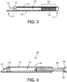
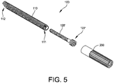
- the nested screw assembly 100 comprises a cannulated outer screw 110 and an inner screw 120 that is threaded into the cannulated outer screw 110.
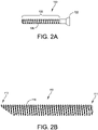
- the inner screw 120 comprises a body, a substantial portion 125 of which is externally threaded with threading 126.
- the internal thread 118 of the outer screw and the external thread 126 of the inner screw have the same thread pitch so that the inner screw 120 can be threaded into the first end 111 of the canal 114 of the outer screw 110 to form the nested screw assembly 100.
- the external thread 116 of the outer screw 110 is also configured to have the same thread pitch and handedness as the internal thread 118 of the outer screw and the external thread 126 of the inner screw.
- the inner screw 120 comprises an oval head 122.
- the head 122 can be provided with a socket 125 for receiving a driver tool bit for screwing/unscrewing the inner screw 120.
- the inner screw 120' is a headless type and comprises a threaded head portion 122' with a thread pitch that is different from the thread pitch of the external thread 116 of the outer screw, the internal thread 118 of the outer screw, and the external thread 126 of the inner screw 120'.
- the thread pitch on the threaded head portion 122' is smaller than the thread pitch of the other threads.
- the outer screw 110 further comprises a driving feature 115 provided inside the canal 114 near the second end 112.
- the driving feature 115 can be a socket, such as a hex socket, star drive socket, etc.
- the driving feature 115 enables the outer screw 110 to be screwed into a bone using an appropriate drive bit inserted into the second end opening 113 (see FIGS. 3-4 ).
- a compression sleeve 200 can be used to drive the inner screw 120' into the outer screw 110.
- the longitudinal cross-sectional view in FIG. 6 shows the nested screw assembly 100 and the compression sleeve 200 engaging the threaded head portion 122' of the inner screw 120'.
- the compression sleeve 200 comprises an internally threaded opening 206 at one end for engaging the threaded head portion 122' of the inner screw 120'.
- the compression sleeve 200 can also be provided with a tool receiving socket 225 on the opposite end for receiving a driver tool for turning the compression sleeve 200.
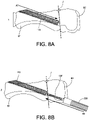
- a method for fusing a joint between a first bone B1 and a second bone B2 using the nested screw assembly 100 comprises the following procedures. First, (a) a hole is pre-drilled into the first bone B1 and the second bone B2 through the joint. The joint is indicated by the line J in FIG. 8A . Then, referring to FIG. 8A , (b) the outer screw 110 is screwed/threaded into the hole in the first bone B1 up to the joint J. The direction of the outer screw's advancement into the first bone B1 is indicated by the arrow A1.
- the inner screw 120' is screwed/threaded into the hole in the second bone B2 from the opposite side until the inner screw 120' engages with the internally threaded portion 119 of the outer screw 110 from the first end 111 of the outer screw and form a nested screw assembly.
- the direction of the inner screw's advancement here is indicated by the arrow A2 in FIG. 8B .
- the inner screw 120' is tightened while holding the outer screw 110 from turning.
- the outer screw 110 can be held in place from turning using a driver tool that is inserted into the second end 112 of the outer screw to engage the driving feature 115 in the canal 114.
- the inner screw 120 can be driven using the compression sleeve 200.
- the compression sleeve 200 As illustrated in FIG. 8B , with the compression sleeve 200 engaged to the threaded head portion 122' of the inner screw 120', because the compression sleeve 200 has a larger diameter than the inner screw 120 and the hole in the second bone B2, as the inner screw 120' is threaded into the outer screw 110 and advanced in the direction of the arrow A2 with respect to the first bone B1 and the outer screw 110, the compression sleeve 200 comes in contact with the second bone B2 and compresses the second bone B2 toward and against the first bone B1 . Once the desired compression of the two bones B1, B2 is achieved, the compression sleeve 200 is removed. See FIG. 8C .
- the nested screw assembly 100 that comprises the oval headed inner screw 120 (see FIG. 2A ) is used, as the inner screw 120 is threaded into the outer screw 110 and advance in the direction of the arrow A2 with respect to the first bone B1 and the outer screw 110, the head 122 of the inner screw 120, rather than the compression sleeve 200, will come into contact with the second bone B2 and compress the second bone B2 toward and against the first bone B1.
- the compression sleeve 200 is not needed as a standard screwdriver can be used with the oval headed inner screw 120.
- the outer screw 110 is screwed further into the hole in the first bone B1 in the direction A1 , toward and across the joint J to maintain the compression of the joint.
- This procedure is carried out while the inner screw 120 is held in place using a driver bit inserted into the tool socket 125 of the inner screw.
- This procedure is possible because the external thread 116 of the outer screw 110 has the same thread pitch and handedness as the internal thread 118 of the outer screw and the external thread 126 of the inner screw.
- the outer screw can be driven across the joint because the outer screw threads across the bone at the same rate it threads over the inner screw 120.
- the threaded head portion 122' of the inner screw 120' is buried into the second bone B2, so that the head portion 122' is not protruding from the bone B2, by driving the inner screw 120' out of the compression sleeve 200.
- This step of burying the head portion 122' of the inner screw 120' into the second bone B2 can be done either before or after the outer screw 110 is advanced across the joint J.
- FIG. 8D shows the position of the headless inner screw 120' after the head portion 122' is buried into the second bone B2.
- FIG. 9 is an illustration showing the nested screw assembly embodiment where the oval headed inner screw 120 is used rather than the headless inner screw 120' after the compression of the bones B1, B2 is completed.
- the outer screw 110 comprises a driving feature 115 provided inside the canal 114 near the second end 112, and the outer screw is threaded into the hole in the procedure (b) by engaging the driving feature 115 with a driving tool.
Landscapes
- Health & Medical Sciences (AREA)
- Orthopedic Medicine & Surgery (AREA)
- Life Sciences & Earth Sciences (AREA)
- Surgery (AREA)
- Medical Informatics (AREA)
- Engineering & Computer Science (AREA)
- Biomedical Technology (AREA)
- Heart & Thoracic Surgery (AREA)
- Nuclear Medicine, Radiotherapy & Molecular Imaging (AREA)
- Molecular Biology (AREA)
- Animal Behavior & Ethology (AREA)
- General Health & Medical Sciences (AREA)
- Public Health (AREA)
- Veterinary Medicine (AREA)
- Neurology (AREA)
- Surgical Instruments (AREA)
- Prostheses (AREA)
Applications Claiming Priority (2)
| Application Number | Priority Date | Filing Date | Title |
|---|---|---|---|
| US202163167901P | 2021-03-30 | 2021-03-30 | |
| US17/653,899 US12201324B2 (en) | 2021-03-30 | 2022-03-08 | Bone fixation implant and method of implantation |
Publications (3)
| Publication Number | Publication Date |
|---|---|
| EP4066762A2 true EP4066762A2 (de) | 2022-10-05 |
| EP4066762A3 EP4066762A3 (de) | 2022-11-30 |
| EP4066762B1 EP4066762B1 (de) | 2025-07-02 |
Family
ID=80735477
Family Applications (1)
| Application Number | Title | Priority Date | Filing Date |
|---|---|---|---|
| EP22161390.4A Active EP4066762B1 (de) | 2021-03-30 | 2022-03-10 | Knochenfixierimplantat |
Country Status (2)
| Country | Link |
|---|---|
| US (2) | US12201324B2 (de) |
| EP (1) | EP4066762B1 (de) |
Families Citing this family (1)
| Publication number | Priority date | Publication date | Assignee | Title |
|---|---|---|---|---|
| US12599419B2 (en) * | 2012-10-19 | 2026-04-14 | Tyber Medical Llc | Beveled screw |
Family Cites Families (11)
| Publication number | Priority date | Publication date | Assignee | Title |
|---|---|---|---|---|
| US4878794A (en) | 1988-03-15 | 1989-11-07 | John W. Hall, Jr. | Collated screw fasteners |
| US6224598B1 (en) | 2000-02-16 | 2001-05-01 | Roger P. Jackson | Bone screw threaded plug closure with central set screw |
| US7204838B2 (en) | 2004-12-20 | 2007-04-17 | Jackson Roger P | Medical implant fastener with nested set screw and method |
| US8343200B2 (en) * | 2006-03-13 | 2013-01-01 | The Johns Hopkins University | Orthopedic screw system |
| DE202007017159U1 (de) | 2007-12-08 | 2008-05-08 | Ferber, Ottfried, Dr.med. | Zugschraubensystem zur Versorgung von Brüchen besonders geeignet bei stabilitätsgeminderten Knochen |
| US9095444B2 (en) * | 2009-07-24 | 2015-08-04 | Warsaw Orthopedic, Inc. | Implant with an interference fit fastener |
| US20120245701A1 (en) * | 2011-03-24 | 2012-09-27 | Rudolf Zak | Hemi Ankle Implant |
| US20130215381A1 (en) | 2012-02-21 | 2013-08-22 | Puthalath Koroth Raghuprasad | Nested screw fastener |
| US10631994B2 (en) * | 2012-10-12 | 2020-04-28 | Smith & Nephew, Inc. | Fusion Implant |
| US9585703B2 (en) * | 2014-09-19 | 2017-03-07 | Agent Medical, Llc | Intramedullary compression screw system |
| TR201610537A2 (tr) | 2016-07-28 | 2016-10-21 | Selim Safali | Ortopedi̇k cerrahi̇ operasyonlar esnasinda kullanilan kalici i̇mplant |
-
2022
- 2022-03-08 US US17/653,899 patent/US12201324B2/en active Active
- 2022-03-10 EP EP22161390.4A patent/EP4066762B1/de active Active
-
2024
- 2024-12-17 US US18/983,517 patent/US20250114126A1/en active Pending
Also Published As
| Publication number | Publication date |
|---|---|
| US12201324B2 (en) | 2025-01-21 |
| EP4066762A3 (de) | 2022-11-30 |
| US20220313328A1 (en) | 2022-10-06 |
| US20250114126A1 (en) | 2025-04-10 |
| EP4066762B1 (de) | 2025-07-02 |
Similar Documents
| Publication | Publication Date | Title |
|---|---|---|
| US6641584B2 (en) | Hook cable for fixing atlantoaxial joint and system for fixing the same | |
| KR100745326B1 (ko) | 다중축 뼈-고정 장치 | |
| US8177823B2 (en) | Orthopedic clamping hook assembly | |
| US7837738B2 (en) | Joint prosthesis and use of screw tool for positioning members thereof | |
| US5961524A (en) | Screw and method of attachment to a substrate | |
| US20090118772A1 (en) | Polyaxial bone anchor with increased angulation | |
| US10182849B2 (en) | Spinal implant locking member with improved guidance, tactile and visual feedback | |
| JP4804757B2 (ja) | 骨接合術用の装置 | |
| US9247971B2 (en) | Endosteal nail plate for fixing bone segments | |
| US8241341B2 (en) | Pedicle screws and methods of using the same | |
| US7691129B2 (en) | Spinal stabilizing system | |
| KR101505568B1 (ko) | 금속정-플레이트 콤비네이션 | |
| US20120283785A1 (en) | Headless compression screw with integrated reduction-compression instrument | |
| US20170325862A1 (en) | Screw with insertion post | |
| EP2085040A1 (de) | Werkzeug zum Halten oder Führen eines Aufnahmeteils zum Verbinden eines Schafts eines Knochenverankerungselements mit einer Stange | |
| US11253306B2 (en) | Tool for the manipulation of fastening devices | |
| KR20080031155A (ko) | 다축 연결 장치 | |
| US20050033300A1 (en) | Bone screw | |
| US20100049249A1 (en) | Suture anchor extension | |
| US20250114126A1 (en) | Bone fixation implant and method of implantation | |
| US20130338716A1 (en) | Polyaxial bone anchoring device | |
| US20040093030A1 (en) | Bone anchor and assembly | |
| CN101237829B (zh) | 骨缝合装置 | |
| US20170340370A1 (en) | Axial Compression Implant | |
| EP3967251A1 (de) | Werkzeuganordnung zur manipulation von schrauben |
Legal Events
| Date | Code | Title | Description |
|---|---|---|---|
| PUAI | Public reference made under article 153(3) epc to a published international application that has entered the european phase |
Free format text: ORIGINAL CODE: 0009012 |
|
| STAA | Information on the status of an ep patent application or granted ep patent |
Free format text: STATUS: REQUEST FOR EXAMINATION WAS MADE |
|
| 17P | Request for examination filed |
Effective date: 20220310 |
|
| AK | Designated contracting states |
Kind code of ref document: A2 Designated state(s): AL AT BE BG CH CY CZ DE DK EE ES FI FR GB GR HR HU IE IS IT LI LT LU LV MC MK MT NL NO PL PT RO RS SE SI SK SM TR |
|
| PUAL | Search report despatched |
Free format text: ORIGINAL CODE: 0009013 |
|
| AK | Designated contracting states |
Kind code of ref document: A3 Designated state(s): AL AT BE BG CH CY CZ DE DK EE ES FI FR GB GR HR HU IE IS IT LI LT LU LV MC MK MT NL NO PL PT RO RS SE SI SK SM TR |
|
| RIC1 | Information provided on ipc code assigned before grant |
Ipc: A61B 17/68 20060101ALI20221026BHEP Ipc: A61B 17/86 20060101AFI20221026BHEP |
|
| RBV | Designated contracting states (corrected) |
Designated state(s): AL AT BE BG CH CY CZ DE DK EE ES FI FR GB GR HR HU IE IS IT LI LT LU LV MC MK MT NL NO PL PT RO RS SE SI SK SM TR |
|
| GRAP | Despatch of communication of intention to grant a patent |
Free format text: ORIGINAL CODE: EPIDOSNIGR1 |
|
| STAA | Information on the status of an ep patent application or granted ep patent |
Free format text: STATUS: GRANT OF PATENT IS INTENDED |
|
| RIC1 | Information provided on ipc code assigned before grant |
Ipc: A61B 17/68 20060101ALI20250206BHEP Ipc: A61B 17/86 20060101AFI20250206BHEP |
|
| INTG | Intention to grant announced |
Effective date: 20250213 |
|
| P01 | Opt-out of the competence of the unified patent court (upc) registered |
Free format text: CASE NUMBER: APP_13823/2025 Effective date: 20250320 |
|
| GRAS | Grant fee paid |
Free format text: ORIGINAL CODE: EPIDOSNIGR3 |
|
| GRAA | (expected) grant |
Free format text: ORIGINAL CODE: 0009210 |
|
| STAA | Information on the status of an ep patent application or granted ep patent |
Free format text: STATUS: THE PATENT HAS BEEN GRANTED |
|
| AK | Designated contracting states |
Kind code of ref document: B1 Designated state(s): AL AT BE BG CH CY CZ DE DK EE ES FI FR GB GR HR HU IE IS IT LI LT LU LV MC MK MT NL NO PL PT RO RS SE SI SK SM TR |
|
| REG | Reference to a national code |
Ref country code: GB Ref legal event code: FG4D |
|
| REG | Reference to a national code |
Ref country code: CH Ref legal event code: EP |
|
| REG | Reference to a national code |
Ref country code: DE Ref legal event code: R096 Ref document number: 602022016669 Country of ref document: DE |
|
| REG | Reference to a national code |
Ref country code: IE Ref legal event code: FG4D |
|
| REG | Reference to a national code |
Ref country code: NL Ref legal event code: MP Effective date: 20250702 |
|
| PG25 | Lapsed in a contracting state [announced via postgrant information from national office to epo] |
Ref country code: PT Free format text: LAPSE BECAUSE OF FAILURE TO SUBMIT A TRANSLATION OF THE DESCRIPTION OR TO PAY THE FEE WITHIN THE PRESCRIBED TIME-LIMIT Effective date: 20251103 |
|
| PG25 | Lapsed in a contracting state [announced via postgrant information from national office to epo] |
Ref country code: NL Free format text: LAPSE BECAUSE OF FAILURE TO SUBMIT A TRANSLATION OF THE DESCRIPTION OR TO PAY THE FEE WITHIN THE PRESCRIBED TIME-LIMIT Effective date: 20250702 |
|
| REG | Reference to a national code |
Ref country code: AT Ref legal event code: MK05 Ref document number: 1808366 Country of ref document: AT Kind code of ref document: T Effective date: 20250702 |
|
| PG25 | Lapsed in a contracting state [announced via postgrant information from national office to epo] |
Ref country code: IS Free format text: LAPSE BECAUSE OF FAILURE TO SUBMIT A TRANSLATION OF THE DESCRIPTION OR TO PAY THE FEE WITHIN THE PRESCRIBED TIME-LIMIT Effective date: 20251102 |
|
| PG25 | Lapsed in a contracting state [announced via postgrant information from national office to epo] |
Ref country code: NO Free format text: LAPSE BECAUSE OF FAILURE TO SUBMIT A TRANSLATION OF THE DESCRIPTION OR TO PAY THE FEE WITHIN THE PRESCRIBED TIME-LIMIT Effective date: 20251002 |
|
| REG | Reference to a national code |
Ref country code: LT Ref legal event code: MG9D |
|
| PG25 | Lapsed in a contracting state [announced via postgrant information from national office to epo] |
Ref country code: AT Free format text: LAPSE BECAUSE OF FAILURE TO SUBMIT A TRANSLATION OF THE DESCRIPTION OR TO PAY THE FEE WITHIN THE PRESCRIBED TIME-LIMIT Effective date: 20250702 |
|
| PG25 | Lapsed in a contracting state [announced via postgrant information from national office to epo] |
Ref country code: FI Free format text: LAPSE BECAUSE OF FAILURE TO SUBMIT A TRANSLATION OF THE DESCRIPTION OR TO PAY THE FEE WITHIN THE PRESCRIBED TIME-LIMIT Effective date: 20250702 |
|
| PG25 | Lapsed in a contracting state [announced via postgrant information from national office to epo] |
Ref country code: HR Free format text: LAPSE BECAUSE OF FAILURE TO SUBMIT A TRANSLATION OF THE DESCRIPTION OR TO PAY THE FEE WITHIN THE PRESCRIBED TIME-LIMIT Effective date: 20250702 |
|
| PGFP | Annual fee paid to national office [announced via postgrant information from national office to epo] |
Ref country code: FR Payment date: 20251231 Year of fee payment: 5 |
|
| PG25 | Lapsed in a contracting state [announced via postgrant information from national office to epo] |
Ref country code: GR Free format text: LAPSE BECAUSE OF FAILURE TO SUBMIT A TRANSLATION OF THE DESCRIPTION OR TO PAY THE FEE WITHIN THE PRESCRIBED TIME-LIMIT Effective date: 20251003 |
|
| PG25 | Lapsed in a contracting state [announced via postgrant information from national office to epo] |
Ref country code: CZ Free format text: LAPSE BECAUSE OF FAILURE TO SUBMIT A TRANSLATION OF THE DESCRIPTION OR TO PAY THE FEE WITHIN THE PRESCRIBED TIME-LIMIT Effective date: 20250702 Ref country code: SE Free format text: LAPSE BECAUSE OF FAILURE TO SUBMIT A TRANSLATION OF THE DESCRIPTION OR TO PAY THE FEE WITHIN THE PRESCRIBED TIME-LIMIT Effective date: 20250702 |
|
| PG25 | Lapsed in a contracting state [announced via postgrant information from national office to epo] |
Ref country code: LV Free format text: LAPSE BECAUSE OF FAILURE TO SUBMIT A TRANSLATION OF THE DESCRIPTION OR TO PAY THE FEE WITHIN THE PRESCRIBED TIME-LIMIT Effective date: 20250702 |
|
| PG25 | Lapsed in a contracting state [announced via postgrant information from national office to epo] |
Ref country code: BG Free format text: LAPSE BECAUSE OF FAILURE TO SUBMIT A TRANSLATION OF THE DESCRIPTION OR TO PAY THE FEE WITHIN THE PRESCRIBED TIME-LIMIT Effective date: 20250702 Ref country code: PL Free format text: LAPSE BECAUSE OF FAILURE TO SUBMIT A TRANSLATION OF THE DESCRIPTION OR TO PAY THE FEE WITHIN THE PRESCRIBED TIME-LIMIT Effective date: 20250702 |
|
| PG25 | Lapsed in a contracting state [announced via postgrant information from national office to epo] |
Ref country code: RS Free format text: LAPSE BECAUSE OF FAILURE TO SUBMIT A TRANSLATION OF THE DESCRIPTION OR TO PAY THE FEE WITHIN THE PRESCRIBED TIME-LIMIT Effective date: 20251002 |
|
| PG25 | Lapsed in a contracting state [announced via postgrant information from national office to epo] |
Ref country code: ES Free format text: LAPSE BECAUSE OF FAILURE TO SUBMIT A TRANSLATION OF THE DESCRIPTION OR TO PAY THE FEE WITHIN THE PRESCRIBED TIME-LIMIT Effective date: 20250702 |
|
| REG | Reference to a national code |
Ref country code: CH Ref legal event code: U11 Free format text: ST27 STATUS EVENT CODE: U-0-0-U10-U11 (AS PROVIDED BY THE NATIONAL OFFICE) Effective date: 20260401 |
|
| PG25 | Lapsed in a contracting state [announced via postgrant information from national office to epo] |
Ref country code: SM Free format text: LAPSE BECAUSE OF FAILURE TO SUBMIT A TRANSLATION OF THE DESCRIPTION OR TO PAY THE FEE WITHIN THE PRESCRIBED TIME-LIMIT Effective date: 20250702 |
|
| PGFP | Annual fee paid to national office [announced via postgrant information from national office to epo] |
Ref country code: GB Payment date: 20260106 Year of fee payment: 5 |
|
| PG25 | Lapsed in a contracting state [announced via postgrant information from national office to epo] |
Ref country code: DK Free format text: LAPSE BECAUSE OF FAILURE TO SUBMIT A TRANSLATION OF THE DESCRIPTION OR TO PAY THE FEE WITHIN THE PRESCRIBED TIME-LIMIT Effective date: 20250702 |
|
| PGFP | Annual fee paid to national office [announced via postgrant information from national office to epo] |
Ref country code: DE Payment date: 20260102 Year of fee payment: 5 |
|
| PG25 | Lapsed in a contracting state [announced via postgrant information from national office to epo] |
Ref country code: IT Free format text: LAPSE BECAUSE OF FAILURE TO SUBMIT A TRANSLATION OF THE DESCRIPTION OR TO PAY THE FEE WITHIN THE PRESCRIBED TIME-LIMIT Effective date: 20250702 |