EP4066802A1 - Plate-forme pour appareils ou équipements médicaux pourvue d'éléments crochets réglables - Google Patents
Plate-forme pour appareils ou équipements médicaux pourvue d'éléments crochets réglables Download PDFInfo
- Publication number
- EP4066802A1 EP4066802A1 EP22165513.7A EP22165513A EP4066802A1 EP 4066802 A1 EP4066802 A1 EP 4066802A1 EP 22165513 A EP22165513 A EP 22165513A EP 4066802 A1 EP4066802 A1 EP 4066802A1
- Authority
- EP
- European Patent Office
- Prior art keywords
- base body
- guide
- platform according
- hook elements
- platform
- Prior art date
- Legal status (The legal status is an assumption and is not a legal conclusion. Google has not performed a legal analysis and makes no representation as to the accuracy of the status listed.)
- Pending
Links
- 230000000149 penetrating effect Effects 0.000 claims description 2
- 229940124645 emergency medicine Drugs 0.000 abstract description 4
- 238000003780 insertion Methods 0.000 description 6
- 230000037431 insertion Effects 0.000 description 6
- 230000001360 synchronised effect Effects 0.000 description 3
- 229910052782 aluminium Inorganic materials 0.000 description 2
- XAGFODPZIPBFFR-UHFFFAOYSA-N aluminium Chemical compound [Al] XAGFODPZIPBFFR-UHFFFAOYSA-N 0.000 description 2
- 229910052751 metal Inorganic materials 0.000 description 2
- 239000002184 metal Substances 0.000 description 2
- 229910000831 Steel Inorganic materials 0.000 description 1
- 208000027418 Wounds and injury Diseases 0.000 description 1
- 238000004140 cleaning Methods 0.000 description 1
- 230000000295 complement effect Effects 0.000 description 1
- 230000006378 damage Effects 0.000 description 1
- 238000013016 damping Methods 0.000 description 1
- 230000003670 easy-to-clean Effects 0.000 description 1
- 230000000694 effects Effects 0.000 description 1
- 230000002349 favourable effect Effects 0.000 description 1
- 208000014674 injury Diseases 0.000 description 1
- 238000004519 manufacturing process Methods 0.000 description 1
- 230000013011 mating Effects 0.000 description 1
- 239000010959 steel Substances 0.000 description 1
- 230000001954 sterilising effect Effects 0.000 description 1
- 238000004659 sterilization and disinfection Methods 0.000 description 1
Images






Classifications
-
- A—HUMAN NECESSITIES
- A61—MEDICAL OR VETERINARY SCIENCE; HYGIENE
- A61G—TRANSPORT, PERSONAL CONVEYANCES, OR ACCOMMODATION SPECIALLY ADAPTED FOR PATIENTS OR DISABLED PERSONS; OPERATING TABLES OR CHAIRS; CHAIRS FOR DENTISTRY; FUNERAL DEVICES
- A61G1/00—Stretchers
- A61G1/04—Parts, details or accessories, e.g. head-, foot-, or like rests specially adapted for stretchers
-
- A—HUMAN NECESSITIES
- A61—MEDICAL OR VETERINARY SCIENCE; HYGIENE
- A61G—TRANSPORT, PERSONAL CONVEYANCES, OR ACCOMMODATION SPECIALLY ADAPTED FOR PATIENTS OR DISABLED PERSONS; OPERATING TABLES OR CHAIRS; CHAIRS FOR DENTISTRY; FUNERAL DEVICES
- A61G13/00—Operating tables; Auxiliary appliances therefor
- A61G13/10—Parts, details or accessories
- A61G13/101—Clamping means for connecting accessories to the operating table
-
- A—HUMAN NECESSITIES
- A61—MEDICAL OR VETERINARY SCIENCE; HYGIENE
- A61G—TRANSPORT, PERSONAL CONVEYANCES, OR ACCOMMODATION SPECIALLY ADAPTED FOR PATIENTS OR DISABLED PERSONS; OPERATING TABLES OR CHAIRS; CHAIRS FOR DENTISTRY; FUNERAL DEVICES
- A61G2203/00—General characteristics of devices
- A61G2203/70—General characteristics of devices with special adaptations, e.g. for safety or comfort
- A61G2203/78—General characteristics of devices with special adaptations, e.g. for safety or comfort for clamping
Definitions
- the object of the invention is to provide a platform that satisfies this requirement profile. You should be fastened quickly and securely to the longitudinal bars or the handles of a stretcher. In addition, it must be able to be flexibly adapted to different dimensions, in particular to different stretchers. This includes different widths of stretchers as well as stretchers whose longitudinal bars have a round or square cross-section.
- a platform for medical devices or equipment with a base body, with at least one mechanical interface for fastening medical device or equipment being present on the base body, with a hook element being arranged on two opposite end faces of the base body, and at least one of the hook elements being connected to the base body via a pull-out guide, so that it can assume different positions relative to the base body.
- the platform according to the invention ultimately comprises a generally rectangular base area with two end faces. On a hook element according to the invention is provided on each of the two end faces. This hook element is used to hang the platform on the longitudinal bars of a patient stretcher and to connect it to these longitudinal bars in a form-fitting manner, so that the platform can be connected to the stretcher securely and captively.
- the platform can be attached at the head end or at the foot end or in a position between the head and foot end of the stretcher.
- At least one of the hook elements is connected to the main body of the platform via a pull-out guide, so that the platform can be adapted to different widths of patient stretchers.
- the pull-out guide allows the hook elements to be slid or inserted over the longitudinal bars of the stretcher in an “open” position.
- the pull-out guide is then retracted a little until the hook elements on both sides of the base body grip the longitudinal bars or the handles of the stretcher. This creates a positive connection between the hook elements and the longitudinal beams.
- the platform is securely and captively connected to the patient stretcher.
- At least one of the hook elements can be displaced relative to the base body against the spring force of a spring element.
- the spring element acts on this hook element in such a way that it assumes a basic position (relative to the base body). If the platform according to the invention is not fixed to a patient stretcher, then the hook element is located in the immediate vicinity of the end face of the base body. Then it takes the mentioned basic position. In other words: In the basic position, the distance between the hook elements is minimal.
- the hook element or elements is/are removed from the end face of the base body with the aid of the pull-out guide(s) and against the force of the spring element.
- This increases the distance between the two hook elements arranged on opposite end faces of the base body. i.e. they assume the above-mentioned "open" position.
- the hook elements can be slid over the longitudinal bars or over the handles of a patient stretcher.
- the optional spring element or a person then ensures that the distance between the hook elements is reduced again. This creates a form fit between the hook elements or the platform and the longitudinal bars of the patient stretcher.
- An advantageous embodiment of the pull-out guide according to the invention provides that it includes a guide sword and guide means, which are formed on the base body.
- the guide blade can be made of plastic, sheet steel or sheet aluminum.
- the guiding means can be, for example, guiding rails which are attached to the underside or top of the platform and interact with the guiding sword.
- the guide means are designed as a prismatic recess in the base body.
- the base body can be produced as a one-part or multi-part plastic injection-molded part in which the recesses and the guide rails are integrated.
- an optional end stop is provided, which effectively prevents the guide blade from being unintentionally pulled out of the recess.
- the guide blade is designed as a sheet metal strip, for example with a cross section of 200 mm ⁇ 4 mm, then the cross section of the recess has a width of, for example, 201 mm and a thickness of 4.5 mm. On the one hand, this ensures that the guide blade can be moved easily in the recess. On the other hand, a sufficiently precise guidance of the guide sword in the recess is guaranteed.
- the optional spring elements are preferably in the form of leaf springs or spiral springs and are particularly preferably arranged inside the base body. Then they do not represent an interference contour and do not get dirty. This facilitates cleaning and, if necessary, sterilization of the platform according to the invention.
- the invention provides that the platform or includes locking means, by means of which one or both hook elements can be locked in their position or in their positions relative to the Body can be locked.
- Such a locking can be realized in that a first toothing is provided on at least one of the guide swords.
- a pawl (preferably spring-loaded) is arranged on the base body. The lock is active when the pawl enters a gap between two teeth of the first toothing. If the pawl is moved against the spring force, it moves out of the tooth gap so that the locking is released.
- a first toothing is provided on both guide swords.
- a pawl (preferably spring-loaded) is arranged on the base body. If both pawls are each in a gap between two teeth of the first toothing, both guide swords are locked. When both pawls are moved out of the tooth gaps, the locks are released.
- the locking means can also be designed as a clamping screw, with the clamping screw penetrating the base body and one or both guide swords and an internal thread is screwed into the base body or a nut.
- the clamping screw When the clamping screw is tightened, the guide blade is clamped and locked in the recess that is part of the pull-out guide.
- the clamping screw penetrates the guide sword in the area of a slot.
- the guide blade can be displaced relative to the clamping screw and, of course, also relative to the base body.
- the guide bar is clamped in the recess of the base body and thus locked.
- the clamping screw also has the function of securing the guide blade in the base body. If the elongated hole in the guide bar is closed at both ends, then the shank of the clamping screw prevents the guide bar from being unintentionally pulled out of the base body.
- the basic form of the hook elements according to the invention is a prismatic body which has a longitudinal extension of about can have 20cm.
- the length of the hook elements roughly corresponds to the width of the platform.
- the hook elements according to the invention have an arcuate or L-shaped cross-section, the arc need not be an arc of a circle. It can also be designed as a polygon and consist of several more or less straight sections arranged at an angle to one another.
- the arc encloses an angle of less than 180°. This creates a lead-in area/lead-in bevel.
- the hook elements can be positively connected to longitudinal bars or handles of different diameters or cross-sectional profiles.
- an inlet bevel is formed at the open end of the arc, as is illustrated in the figures in a wide variety of embodiments.
- At least one of the two hook elements is detachably connected to the guide sword or the main body of the platform and can be connected to the guide sword or the main body of the platform in two or more positions.
- the hook elements on the envelope can be in two different positions with the Guide sword to be connected. This is illustrated below with reference to the figures.
- a further flexibilization and expansion of the possible uses of the platform according to the invention is achieved if one of the hook elements is rotatably attached to the guide sword or the base body. It is then also possible for the hook elements to be fastened in a form-fitting manner to bars of a patient stretcher that do not run parallel to one another (skew) or to another object from the field of emergency medicine.
- the hook elements preferably have one or more recesses. These recesses can be used to positively connect the hook element, for example, to an end piece of a handle in the axial direction of the longitudinal bar. Such end pieces are often designed as a diameter extension, for example in the form of a mushroom-like head.
- this head does not interfere with the secure form fit between the platform according to the invention and the longitudinal bars of a patient stretcher.
- a further improvement in handling and resilience is achieved when the movements of the guide swords are mechanically synchronized.
- second toothings are formed on the guide swords, and that these second toothings mesh with one and the same rotatably mounted pinion. This ensures that the guide swords or the hook elements arranged on them are located symmetrically to a center of the base body.
- a further embodiment of a mechanical synchronization of the movements of the guide swords can be realized by a "scissors lattice.
- figure 1 shows an isometric view of a first exemplary embodiment of a platform 1 according to the invention with a base body 3 and with a rectangular base area, on the end faces of which a hook element 5 is arranged in each case.
- the hook elements 5 are not firmly fastened to the end face of the base body 3, but indirectly with the aid of a pull-out guide.
- the hook elements are located in the immediate vicinity of the end faces of the base body. To a certain extent, this position is the basic position of the platform. The platform assumes the home position when not attached to a gurney.
- the base body 3 of the platform has at least one mechanical interface for attaching medical equipment or devices.
- This mechanical interface is usually on the top of the base body 3. It is not shown in the figures.
- the mechanical interface can be in the form of threaded sleeves that are fastened, for example, to the four corners of the base body 3 .
- the pull-out guide shown comprises a guide blade 7 which is inserted into a complementary shaped recess in the base body 3.
- the guide sword 7 can, for example, be a metal sheet in the middle of which there is an elongate opening 11 .
- This breakthrough 11 can have different functions. It can be part of a locking device, with the help of which or the Guide swords 7 can be locked relative to the base body 3.
- the breakthrough 11 of a guide sword 7 can be penetrated by a clamping screw.
- the clamping screw is in the in figure 2 not shown; only the longitudinal axes of the clamping screws are in the figure 2 indicated by dash-dotted line 13.
- the head of the clamping screw rests on the upper side of the base body 3 and the shank of the clamping screw penetrates the opening 11, then provided that the opening 11 does not go through to the end of the guide bar 7, it is ensured that the guide bar 7 cannot be pulled out of the base body 3 or the recess 9 of the base body 3 . This is only possible if the clamping screw is removed.
- the guide blade 7 can be clamped in the recess 9 by tightening the clamping screw and the position of the guide blade can be locked in this way. This also determines the position of the hook element 5 attached to the guide bar 7 relative to the base body 3; the hook element 5 is locked.
- the mating thread for the clamping screw (not shown) can either be formed directly into the underside of the base body 3 . It is also possible to provide a sleeve nut on the underside of the base body 3 which, together with the thread of the clamping screw, causes the guide sword 7 to be clamped.
- clamping screw it is also possible for the clamping screw to be designed as a quick-action clamping screw, for example with a clamping lever. Such quick releases have been known in bicycles for decades.
- FIG 4 the curved and slightly open profile of the hook elements 4 is also clearly visible.
- An insertion bevel 17 can be seen at the open end of this "arc".
- This insertion bevel 17 is also formed in the other exemplary embodiments. It has the following effects: It facilitates the creation of a form fit between the hook elements 5 and the longitudinal bar 43 of a patient stretcher 41 (see figure 17 ). On the other hand, it also expands the area of use of the hook elements 5 Longitudinal bars with a larger diameter or other cross-sections (e.g. square tube).
- FIG. 5 an exemplary embodiment is shown in which the hook element 5 arranged on the right-hand edge of the picture is rotatably fastened to the guide sword 7 .
- This can be done, for example, with the help of a central fastening screw (not shown).
- the axis of rotation of this hook element 5 runs parallel to a longitudinal axis of the base body 3 or of the guide sword 7. For reasons of clarity, it is shown in FIG figure 5 not shown.
- the hook elements 5 can also be positively and securely fastened to rods, pipes or other components that are skewed to one another.
- the base body 3 is formed in three parts. It comprises a central part 3M and two side parts 3S which are articulated to the central part 3M. The joint between each side part 3S and the middle part 3M can pivot through an angle of about 180°.
- This locking can take place, for example, in that a pivot axis 19 of the joint is formed by a screw. The joint or hinge is locked by tightening the screw.
- the screw can be a socket head screw with the head in figure 6 is sunk on the viewer-facing side of the center portion 3M. There is an internal thread on the side of the central part 3M facing away from the viewer. When this screw is tightened, the part of the side part 3S that forms part of the hinge is clamped between the two projections of the middle part 3M. In this way the hinge is locked in position.
- the Figures 7 to 10 show different constellations of the relative position of the middle part 3M to the side parts 3S in connection with different positions of the hook elements 5 relative to the respective guide sword 7.
- the hook elements 5 of the platform according to the invention can be attached to a tube, be it a longitudinal beam 43 of a Patient stretcher 41 (see figure 17 ), a board or another object to be hung. This results in the great flexibility of the platform 1 according to the invention.
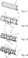
- FIGs 11 to 14 various embodiments of hook elements 5 according to the invention are shown.
- a hook element 5 is shown, which can be produced, for example, as an extruded profile made of plastic or aluminum. It has a prismatic cross-section and no recess.
- the hook element 5 has two recesses 21 .
- a part of the hook element 5 remains between the recesses 21 and is designed as a handle 23 in this exemplary embodiment.
- This handle 23 is on the in figure 12 connected to the upper part of the hook element where the holes for the fastening screws 15 are provided.
- a grip bar 25 is visible. If you hold the hook element 5 on this grip strip 25, it is very easy to move the hook element 5 together with the guide blade 7 in its position relative to the base body 3 (see, for example, Figures 1 to 3 ) and then lock it in this position.
- FIG. 13 and 14 show further variants of hook elements 5 according to the invention figure 13 is compared to the embodiment according to figure 12 optimized for weight. For this reason, several openings (without reference numbers) are formed there, that reduce the overall weight.
- the exemplary embodiment according to FIG. 14 is also optimized in terms of weight. A total of three recesses 21 are provided; accordingly, two handle parts 23 are present.
- FIG 15 is the positive connection between the hook element according to figure 12 and the handle 45 of a stretcher 41 shown in detail.
- the longitudinal beam 43 of the stretcher is in the figure 15 also shown.
- the handle 45 is located at one end of a longitudinal beam 43.
- an end piece 47 is formed, which ultimately represents an increase in the diameter of the handle 45.
- the recesses 21 in the hook element 5 are dimensioned such that one of the recesses 21 can receive the end part 47 of the handle 45 .
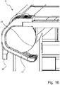
- the hook element 5 illustrated consists of the arcuate contour of four straight sections, if the insertion bevel 17 is also included. These straight sections are connected by radii and enclose an angle of less than 180°. Therefore, the insertion bevel 17 is not parallel to the upper side of the hook element 5 or not parallel to the plane in which the guide sword 7 is located.
- the insertion bevel 17 in conjunction with the upper area of the hook element, ensures that the hook element 5 rests against the handle 45 and forms a form fit.
- the insertion bevel 17 also ensures that there is no play between the hook element and the handle 45 .
- the hook element 5 in cross section not to be composed of a series of straight sections. It is also possible to design the hook element as a continuously curved arc. is preferred the radius of the arc in the direction of the chamfer 17 is larger. In the figure 16 the handle strip 25 can also be seen.
- the platform according to the invention enables a mechanical interface for medical devices and equipment to be fastened quickly, safely and flexibly to a wide variety of patient stretchers, hospital transporters or other equipment. There are hardly any limits to the possible uses due to the great flexibility, the platform and the design of the hook elements 5 according to the invention.
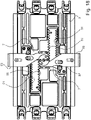
- the figures 18 and 19 show an embodiment of locking means and a device for synchronizing.
- a first set of teeth 51 is provided on both guide swords 7 .
- a pawl 53 (preferably spring-loaded) is arranged on the base body 3 .
- the pawl 53 is moved into a gap between two teeth of the first toothing 51, so that the arresting/locking of both guide swords 7 is active. If the pawl is moved against the spring force, it moves out of the tooth gap so that the locking is released. This situation is in the figure 19 shown.
- the pawls 53 are coupled to one another via a cam mechanism that is not described in detail in such a way that they move synchronously and they always occupy the same position in relation to the first toothing 51 assigned to them. It is then ensured that both guide swords 7 are either locked or their locks are not active. This has the advantage, among other things, that the locking can be operated with one hand.
- a device for synchronizing is shown, which is implemented by a "scissors-type grating" 59 .
Landscapes
- Health & Medical Sciences (AREA)
- Life Sciences & Earth Sciences (AREA)
- Animal Behavior & Ethology (AREA)
- General Health & Medical Sciences (AREA)
- Public Health (AREA)
- Veterinary Medicine (AREA)
- Engineering & Computer Science (AREA)
- Biomedical Technology (AREA)
- Accommodation For Nursing Or Treatment Tables (AREA)
Applications Claiming Priority (1)
| Application Number | Priority Date | Filing Date | Title |
|---|---|---|---|
| DE102021108460.1A DE102021108460A1 (de) | 2021-04-01 | 2021-04-01 | Plattform für medizinische Geräte oder Ausrüstung mit einstellbaren Hakenelementen |
Publications (1)
| Publication Number | Publication Date |
|---|---|
| EP4066802A1 true EP4066802A1 (fr) | 2022-10-05 |
Family
ID=80999978
Family Applications (1)
| Application Number | Title | Priority Date | Filing Date |
|---|---|---|---|
| EP22165513.7A Pending EP4066802A1 (fr) | 2021-04-01 | 2022-03-30 | Plate-forme pour appareils ou équipements médicaux pourvue d'éléments crochets réglables |
Country Status (2)
| Country | Link |
|---|---|
| EP (1) | EP4066802A1 (fr) |
| DE (1) | DE102021108460A1 (fr) |
Families Citing this family (1)
| Publication number | Priority date | Publication date | Assignee | Title |
|---|---|---|---|---|
| DE102021115484A1 (de) | 2021-06-15 | 2022-12-15 | Starmed GmbH | Träger für ein medizinisches Gerät |
Citations (4)
| Publication number | Priority date | Publication date | Assignee | Title |
|---|---|---|---|---|
| US20040088793A1 (en) * | 2000-11-21 | 2004-05-13 | Guido Koch | Arrangement for holding accessory parts to a patient support surface |
| US20090169831A1 (en) * | 2003-10-20 | 2009-07-02 | Malcolm Roger J | Co-molded elements in reinforced resin composites |
| EP2774592A1 (fr) * | 2005-04-11 | 2014-09-10 | Allen Medical Systems, Inc. | Appareil de support de corps pour chirurgie spinale |
| US20170196477A1 (en) * | 2016-01-13 | 2017-07-13 | St. Jude Medical, Cardiology Division, Inc. | Mounting assembly for a magnetic field generator |
-
2021
- 2021-04-01 DE DE102021108460.1A patent/DE102021108460A1/de active Pending
-
2022
- 2022-03-30 EP EP22165513.7A patent/EP4066802A1/fr active Pending
Patent Citations (4)
| Publication number | Priority date | Publication date | Assignee | Title |
|---|---|---|---|---|
| US20040088793A1 (en) * | 2000-11-21 | 2004-05-13 | Guido Koch | Arrangement for holding accessory parts to a patient support surface |
| US20090169831A1 (en) * | 2003-10-20 | 2009-07-02 | Malcolm Roger J | Co-molded elements in reinforced resin composites |
| EP2774592A1 (fr) * | 2005-04-11 | 2014-09-10 | Allen Medical Systems, Inc. | Appareil de support de corps pour chirurgie spinale |
| US20170196477A1 (en) * | 2016-01-13 | 2017-07-13 | St. Jude Medical, Cardiology Division, Inc. | Mounting assembly for a magnetic field generator |
Also Published As
| Publication number | Publication date |
|---|---|
| DE102021108460A1 (de) | 2022-10-06 |
Similar Documents
| Publication | Publication Date | Title |
|---|---|---|
| DE60030669T2 (de) | Strukturelemente und zugehörige Teile | |
| DE60125928T2 (de) | Äusserer einwegfixateur | |
| DE4439644C2 (de) | Verriegelungssystem für Beschläge von Fahrzeugsitzen mit freischwenkbarer Rückenlehne | |
| DE202004021652U1 (de) | Fördereinrichtung | |
| EP1394012B1 (fr) | Dispositif de fixation pour deux elements monté coulissant l'un par rapport à l'autre | |
| EP2907469B1 (fr) | Servante d'outillage | |
| EP0913139B1 (fr) | Système de table d'opération modulaire | |
| EP4066802A1 (fr) | Plate-forme pour appareils ou équipements médicaux pourvue d'éléments crochets réglables | |
| EP3464147A1 (fr) | Profilés de rail détachables destinés à être utilisés avec des aides à la montée | |
| DE2736037C3 (de) | Steigschutzvorrichtung | |
| DE3447178C2 (fr) | ||
| DE202004014288U1 (de) | Intraamedullärer Verriegelungsnagel | |
| DE102010014054B4 (de) | Öffnungshilfe für Energieführungsketten | |
| EP3988049B1 (fr) | Dispositif distracteur | |
| DE202016107514U1 (de) | Anordnung zur Sicherung eines Bettinsassen gegen ein Herausfallen aus einem Bett, insbesondere einem Pflegebett, und Bett, insbesondere Pflegebett mit einer Sicherungsanordnung | |
| DE102009051594B4 (de) | Haken, insbesondere für Sicherheitseinrichtungen | |
| DE29516477U1 (de) | Futtergitter | |
| DE202021102535U1 (de) | Höhenverstellbares Füßchen für Möbelstücke | |
| DE102011008349B4 (de) | Höhenanpassbare Sicherung für eine Fitting-Bajonettverriegelung an einer Rohrleitungsarmatur | |
| EP1679044B1 (fr) | Set pour la création d'un implant d'ostéosynthèse | |
| DE102010045809B4 (de) | Vorrichtung zum Einsetzen eines Kämpfers in einen Tür- oder Fensterrahmen | |
| DE102017130409B4 (de) | Vorrichtung, insbesondere Sitzschale, mit mehreren beweglichen Verstellelementen | |
| EP3406916B1 (fr) | Équerre pour profilés de support | |
| AT413726B (de) | Vorrichtung zum anschlagen eines ladens eines fensters oder einer tür | |
| AT395804B (de) | Verschlusseinrichtung |
Legal Events
| Date | Code | Title | Description |
|---|---|---|---|
| PUAI | Public reference made under article 153(3) epc to a published international application that has entered the european phase |
Free format text: ORIGINAL CODE: 0009012 |
|
| STAA | Information on the status of an ep patent application or granted ep patent |
Free format text: STATUS: THE APPLICATION HAS BEEN PUBLISHED |
|
| AK | Designated contracting states |
Kind code of ref document: A1 Designated state(s): AL AT BE BG CH CY CZ DE DK EE ES FI FR GB GR HR HU IE IS IT LI LT LU LV MC MK MT NL NO PL PT RO RS SE SI SK SM TR |
|
| STAA | Information on the status of an ep patent application or granted ep patent |
Free format text: STATUS: REQUEST FOR EXAMINATION WAS MADE |
|
| 17P | Request for examination filed |
Effective date: 20230404 |
|
| RBV | Designated contracting states (corrected) |
Designated state(s): AL AT BE BG CH CY CZ DE DK EE ES FI FR GB GR HR HU IE IS IT LI LT LU LV MC MK MT NL NO PL PT RO RS SE SI SK SM TR |
|
| STAA | Information on the status of an ep patent application or granted ep patent |
Free format text: STATUS: EXAMINATION IS IN PROGRESS |
|
| 17Q | First examination report despatched |
Effective date: 20241104 |