EP4067229B1 - Appareils de stabilisation de décollage et d'atterrissage de véhicule aérien vertical - Google Patents
Appareils de stabilisation de décollage et d'atterrissage de véhicule aérien vertical Download PDFInfo
- Publication number
- EP4067229B1 EP4067229B1 EP22160423.4A EP22160423A EP4067229B1 EP 4067229 B1 EP4067229 B1 EP 4067229B1 EP 22160423 A EP22160423 A EP 22160423A EP 4067229 B1 EP4067229 B1 EP 4067229B1
- Authority
- EP
- European Patent Office
- Prior art keywords
- vtol
- oriented support
- landing
- support element
- cooperating
- Prior art date
- Legal status (The legal status is an assumption and is not a legal conclusion. Google has not performed a legal analysis and makes no representation as to the accuracy of the status listed.)
- Active
Links
Images









Classifications
-
- B—PERFORMING OPERATIONS; TRANSPORTING
- B64—AIRCRAFT; AVIATION; COSMONAUTICS
- B64U—UNMANNED AERIAL VEHICLES [UAV]; EQUIPMENT THEREFOR
- B64U70/00—Launching, take-off or landing arrangements
- B64U70/70—Launching or landing using catapults, tracks or rails
-
- B—PERFORMING OPERATIONS; TRANSPORTING
- B64—AIRCRAFT; AVIATION; COSMONAUTICS
- B64C—AEROPLANES; HELICOPTERS
- B64C27/00—Rotorcraft; Rotors peculiar thereto
- B64C27/04—Helicopters
- B64C27/08—Helicopters with two or more rotors
-
- B—PERFORMING OPERATIONS; TRANSPORTING
- B64—AIRCRAFT; AVIATION; COSMONAUTICS
- B64C—AEROPLANES; HELICOPTERS
- B64C27/00—Rotorcraft; Rotors peculiar thereto
- B64C27/006—Safety devices
-
- B—PERFORMING OPERATIONS; TRANSPORTING
- B64—AIRCRAFT; AVIATION; COSMONAUTICS
- B64C—AEROPLANES; HELICOPTERS
- B64C29/00—Aircraft capable of landing or taking-off vertically, e.g. vertical take-off and landing [VTOL] aircraft
-
- B—PERFORMING OPERATIONS; TRANSPORTING
- B64—AIRCRAFT; AVIATION; COSMONAUTICS
- B64C—AEROPLANES; HELICOPTERS
- B64C39/00—Aircraft not otherwise provided for
- B64C39/02—Aircraft not otherwise provided for characterised by special use
- B64C39/024—Aircraft not otherwise provided for characterised by special use of the remote controlled vehicle type, i.e. RPV
-
- B—PERFORMING OPERATIONS; TRANSPORTING
- B64—AIRCRAFT; AVIATION; COSMONAUTICS
- B64F—GROUND OR AIRCRAFT-CARRIER-DECK INSTALLATIONS SPECIALLY ADAPTED FOR USE IN CONNECTION WITH AIRCRAFT; DESIGNING, MANUFACTURING, ASSEMBLING, CLEANING, MAINTAINING OR REPAIRING AIRCRAFT, NOT OTHERWISE PROVIDED FOR; HANDLING, TRANSPORTING, TESTING OR INSPECTING AIRCRAFT COMPONENTS, NOT OTHERWISE PROVIDED FOR
- B64F1/00—Ground or aircraft-carrier-deck installations
-
- B—PERFORMING OPERATIONS; TRANSPORTING
- B64—AIRCRAFT; AVIATION; COSMONAUTICS
- B64U—UNMANNED AERIAL VEHICLES [UAV]; EQUIPMENT THEREFOR
- B64U30/00—Means for producing lift; Empennages; Arrangements thereof
- B64U30/20—Rotors; Rotor supports
- B64U30/29—Constructional aspects of rotors or rotor supports; Arrangements thereof
- B64U30/299—Rotor guards
-
- B—PERFORMING OPERATIONS; TRANSPORTING
- B64—AIRCRAFT; AVIATION; COSMONAUTICS
- B64U—UNMANNED AERIAL VEHICLES [UAV]; EQUIPMENT THEREFOR
- B64U70/00—Launching, take-off or landing arrangements
- B64U70/90—Launching from or landing on platforms
- B64U70/97—Means for guiding the UAV to a specific location on the platform, e.g. platform structures preventing landing off-centre
-
- B—PERFORMING OPERATIONS; TRANSPORTING
- B64—AIRCRAFT; AVIATION; COSMONAUTICS
- B64U—UNMANNED AERIAL VEHICLES [UAV]; EQUIPMENT THEREFOR
- B64U10/00—Type of UAV
- B64U10/10—Rotorcrafts
- B64U10/13—Flying platforms
- B64U10/14—Flying platforms with four distinct rotor axes, e.g. quadcopters
-
- B—PERFORMING OPERATIONS; TRANSPORTING
- B64—AIRCRAFT; AVIATION; COSMONAUTICS
- B64U—UNMANNED AERIAL VEHICLES [UAV]; EQUIPMENT THEREFOR
- B64U2101/00—UAVs specially adapted for particular uses or applications
- B64U2101/60—UAVs specially adapted for particular uses or applications for transporting passengers; for transporting goods other than weapons
-
- B—PERFORMING OPERATIONS; TRANSPORTING
- B64—AIRCRAFT; AVIATION; COSMONAUTICS
- B64U—UNMANNED AERIAL VEHICLES [UAV]; EQUIPMENT THEREFOR
- B64U30/00—Means for producing lift; Empennages; Arrangements thereof
- B64U30/20—Rotors; Rotor supports
-
- B—PERFORMING OPERATIONS; TRANSPORTING
- B64—AIRCRAFT; AVIATION; COSMONAUTICS
- B64U—UNMANNED AERIAL VEHICLES [UAV]; EQUIPMENT THEREFOR
- B64U70/00—Launching, take-off or landing arrangements
- B64U70/90—Launching from or landing on platforms
- B64U70/99—Means for retaining the UAV on the platform, e.g. dogs or magnets
-
- B—PERFORMING OPERATIONS; TRANSPORTING
- B64—AIRCRAFT; AVIATION; COSMONAUTICS
- B64U—UNMANNED AERIAL VEHICLES [UAV]; EQUIPMENT THEREFOR
- B64U80/00—Transport or storage specially adapted for UAVs
- B64U80/10—Transport or storage specially adapted for UAVs with means for moving the UAV to a supply or launch location, e.g. robotic arms or carousels
Definitions
- the present disclosure relates generally to the field of vertical lift-off and vertical descent air vehicles. More specifically, the present disclosure relates to improving the use of vertical lift-off and vertical descent vehicles in proximity to inhabited locations.
- Rotor-driven aircraft e.g., rotorcraft
- drones non-crewed smaller-scale rotorcraft collectively referred to as "drones”
- Such "vertical air vehicles” can create significant air turbulence, noise, and safety issues during takeoff and landing, and otherwise adversely impact structures and people located at ground level during, for example, takeoff and landing.
- the vehicles themselves can incur damage due to instability due to ground effect turbulence during takeoff and landing.
- US 2019/202578 A1 relates to a centering system for positioning an Unmanned Autonomous Vehicle (UAV) provided with two or more supporting extremities rigidly connected thereto, comprising a pair of displaceable positioning elements provided with surfaces sloped relative to each other, which create trapping areas such that when said positioning elements are caused to move one relative to the other, said two or more supporting extremities are caused to be trapped in said trapping areas.
- UAV Unmanned Autonomous Vehicle
- US 2013/313364 A1 relates to system that includes a ground unit that includes: a takeoff and landing platform; a landing and takeoff assisting module; and a housing.
- the takeoff and landing platform is arranged to hold and support an aerial unit during a first part of a landing process of the aerial unit and a first part of takeoff process of the aerial unit.
- the aerial unit is coupled to the ground unit via a connecting element. The effective length of the connecting element increases during the takeoff process and decreases during the landing process.
- the landing and takeoff assisting module is coupled to the takeoff and landing platform and is arranged to (a) lower the takeoff and landing platform into the housing during a second part of the landing process and (b) elevate the takeoff and landing platform during a second part of the takeoff process.
- US 2016/200438 A1 states that methods and associated systems for autonomous package delivery utilize a UAS/UAV, an infrared positioning senor, and a docking station integrated with a package delivery vehicle.
- the UAS/UAV accepts a package for delivery from the docking station on the delivery vehicle and uploads the delivery destination.
- the UAS/UAV autonomously launches from its docked position on the delivery vehicle.
- the UAS/UAV autonomously flies to the delivery destination by means of GPS navigation.
- the UAS/UAV is guided in final delivery by means of a human supervised live video feed from the UAS/UAV.
- the UAS/UAV is assisted in the descent and delivery of the parcel by precision sensors and if necessary by means of remote human control.
- the UAS/UAV autonomously returns to the delivery vehicle by means of GPS navigation and precision sensors.
- the UAS/UAV autonomously docks with the delivery vehicle for recharging and preparation for the next delivery sequence.
- an UAVMCS can include a base structure connected to a power grid, a station receiving assembly, a remote controller at the base structure enabled to communicate with a UAV and to initiate, control and stop docking and charging processes, a housing with covers, a positioning and stabilizing surface, and a UAV docking charging and refueling frame used for connecting to the docking housing unit.
- the UAVMCS can be mounted on towers, bridges, posts, electricity pylons, communication structures, buildings, and gas stations, but is not limited to them.
- the UAVMCS can serve as a UAV garage and as a place for storage of packages, as an outdoor lighting facility, and perform other functions.
- US 2019/276147 A1 relates to a drone takeoff and landing system that comprises: a drone including a through-hole; and a landing pad including an extension member which can pass through the through-hole, wherein, when the extension member of the landing pad passes through the through-hole of the drone, an eddy current may occur between the through-hole and the extension member to cause magnetic braking of the drone.
- UAV unmanned aerial vehicle
- a rotary-wing air vehicle comprises a main body and at least two rotor devices and arranged and configured to generate propulsion and thrust, in use, to lift and propel said air vehicle.
- the rotor devices are arranged and configured relative to the main body such that the blades thereof do not cross through a central vertical axis of the main body defining the center of mass thereof.
- the main body is provided with an aperture that extends therethrough to define a channel about said central vertical axis.
- an apparatus for launch and recovery of the air vehicle that comprises an elongate pole member that in use extends through the channel defined by the aperture in the main body. A method of launching and recovery of the air vehicle is also disclosed.
- VTOLs vertical takeoff and landing vehicles
- rotorcraft that obviate the need for runways, etc.
- drawbacks to an increased adoption of VTOLs, including commercial use of VTOLs include increased localized noise, ground effect from the rotors, safety issues, likelihood of incurring damage to VTOLs or land-based structures during takeoff and landing, etc.
- various factors can impact VTOL stability, flight, and performance during takeoff and landing, including wind gusts, etc.
- Present methods, systems, and apparatuses address, significantly ameliorate, and/or eliminate drawbacks to the widespread (e.g., commercial) adoption of VTOLs, and further facilitate the increased use of VTOLs, including a widespread adoption of VTOLs in inhabited areas, including inhabited areas having dense human populations.
- an apparatus for stabilizing launch and landing of a vertical takeoff and landing vehicle.
- the apparatus includes a vertically-oriented support element, with the vertically-oriented support element including a vertically-oriented support element first end and a vertically-oriented support element second end.
- the vertically-oriented support element second end extends from the vertically-oriented support element first end, with the vertically-oriented support element second end located at a selected distance away from the vertically-oriented support element first end, with the vertically-oriented support element further including at least one first cooperating stabilizer element, with the at least one first cooperating stabilizer element located proximate to the vertically-oriented support element second end, and wherein the at least one first cooperating stabilizer element includes a female attachment portion.
- the vertically-oriented support element second end is located a distance from the vertically-oriented support element first end, said distance ranging from about 1.22 m (4 ft.) to about 30.48 m (100 ft.).
- the vertically-oriented support element second end is located a distance from the vertically-oriented support element first end, said distance ranging from about 1 ft. to about 10 ft.
- the at least one first cooperating stabilizer element is configured to extend outwardly from the vertically-oriented support element.
- the first cooperating stabilizer element includes a female attachment portion dimensioned to receive a second cooperating stabilizer portion, with the second cooperating stabilizer element comprising a male attachment portion.
- the female attachment portion includes a slot, with the slot located at the vertically-oriented support element second end, and with the slot extending a selected distance from the vertically-oriented support element second end longitudinally along the length of the vertically-oriented support element.
- the apparatus further includes a guide, with the guide in communication with the vertically-oriented support element second end, and with the guide including the at least one first cooperating stabilizer element.
- VTOLs vertical takeoff and landing vehicles
- payloads e.g., packages, equipment, etc.
- payloads e.g., packages, equipment, etc.
- payloads e.g., packages, equipment, etc.
- significant issues that occur during the takeoff and landing of VTOLs such as, for example, noise, excessive turbulence caused by rotor generated ground effect air pressure, vehicle instability, safety concerns, ground structure damage, VTOL damage, etc.
- directional airflow generated by a VTOL during takeoff and landing can generate air turbulence including air turbulence referred to as "ground effect" that can de-stabilize and otherwise interfere with, and otherwise increase the difficulty of a VTOL's takeoff and landing protocol.
- a VTOL is engaged in a landing (e.g., a descent from an airborne position to the ground or other solid structure, landing pad, etc., that may be located above or below ground level)
- airflow pressure can be generated by the operating rotors in a directional airflow from rotors that can be initially "downward" from the VTOL, and then "outward" and away from the VTOL.
- the airflow from the rotors dissipates, at least to an extent, with minimal or no deflected return airflow from the rotors directed back toward, or otherwise impacting the VTOL.
- the initial airflow pressure generated from the rotors impacts the ground and is deflected back as deflected airflow pressure in, at least an upward direction from the ground back to the VTOL.
- the airflow directional deflections progressively increase as the VTOL nears a landing location (e.g., ground, landing pad, etc.).
- the maximum airflow directional deflection can typically occur at the point in time that the VTOL "lands" and the VTOL impacts a landing location, and the airflow directional deflections can destabilize the VTOL, cause vibrations, buffeting, turbulence, etc.
- air turbulence increases as directional airflow not only deflects from the ground vertically back to the VTOL (e.g., in an upward direction), but directional airflow also is deflected in non-vertical directions that can interrupt or "cut through" the downward airflow from the rotors, and that can contribute to VTOL instability and otherwise contribute to an increasing lateral force and an increasing vertical force (e.g., an increase in forces associated with and forces that can otherwise contribute to, for example, pitch, roll , and yaw, etc.) on the VTOL during landing (and takeoff).
- ground effect Such forces can frustrate and otherwise render an unpredictable and turbulent VTOL landing, rather than a desired smooth and turbulence-free VTOL landing devoid of such omnipresent variable and potentially destabilizing vertical and lateral forces imposed on the VTOL.
- the combined effects of airflow deflection caused by rotor generated airflow impacting and being deflected from a landing surface (e.g., ground, landing pad, etc.) and the resulting air turbulence and force converted from a downward direction to a lateral direction is collectively referred to herein as "ground effect".
- Such undesirable forces impacting on a VTOL can hinder the takeoff and/or landing and imperil ground structures, damage the VTOL, injure ground personnel, etc., as airflow directional deflections reach a maximum effect and that can further destabilize the VTOL, causing vibrations, buffeting, turbulence, etc.
- the actuated rotational vehicle fixtures that provide the mechanical forces necessary for vertical lift of the VTOLs can be vertical propulsion units including, for example, jets, propellers, and rotors, with the vertical propulsion units equivalently and interchangeably referred to herein as "rotors". That is, the term "rotors" as used herein includes propellers, vertical propulsion units, jets, and rotors.
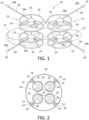
- FIG. 1 shows a VTOL 20 not presently being claimed, but useful for understanding aspects of the claimed apparatus, including a vehicle body 22, a battery 21 (that can be a rechargeable battery), with at least one rotor assembly 23 (shown in FIG. 1 as four rotor assemblies) in communication with the vehicle body 22.
- the rotor assembly 23 comprises a rotor 24 with a rotor guard 26 oriented circumferentially to protect the rotor, with the rotor guard having a radius exceeding the length of the rotor such that the rotor, in operation, does not impact the rotor guard.
- FIG. 1 further shows a standoff 28 having a standoff first end 28a attached to or integral with and outwardly extending from a rotor guard 26.
- Each standoff 28 further comprises a standoff second end 28b terminating in a second cooperating stabilizer element 29.
- Second cooperating stabilizer element 29 of standoff 28 is configured to attach to a first cooperating stabilizer element 34 of a vertically-oriented support element 32 in an apparatus 30, as shown in FIG. 2 .
- the term "vertically-oriented support element” is defined as a support element comprising an angle measured at the vertically-oriented support element first end with respect to a plane established by a substantially horizontal base or with respect to a plane establish substantially perpendicular to the vertically-oriented support element first end, and with the angle ranging from about 10° to about 90°, preferably with the angle ranging from about 30° to about 90°, and more preferably with the angle ranging from about 70° to about 90°.
- FIG. 2 shows an overhead view (e.g., a "top” view) of the VTOL 20 shown in FIG 1 in a process that includes landing and coming into contact with apparatus 30 such that the second cooperating stabilizer element 29 of each standoff 28 extending from VTOL 20 has engaged first cooperating stabilizer element 34 (shown as a "slot") of each of the four vertically-oriented support elements 32 of apparatus 30.
- the second cooperating stabilizer element 29 of the standoff 28 of the VTOL 20 is shown as a "male” fixture that engages or is inserted into the "female” or receiving first cooperating stabilizer element 34 of the vertically-oriented support element 32.
- the remainder of the elements of the VTOL 20 shown in FIG. 2 are numbered in similar fashion to that as provided in FIG. 1 .
- a VTOL can include standoffs 28 that incorporate a second incorporating element 29 that can be a male fixture configured to engage and become inserted into a second cooperating feature on a vertically-oriented support element that can include a female fixture (that can be configured and dimensioned to engage with the male fixture of the first cooperating stabilizer element 29 of the standoff 28 located on the VTOL).
- a second incorporating element 29 can be a male fixture configured to engage and become inserted into a second cooperating feature on a vertically-oriented support element that can include a female fixture (that can be configured and dimensioned to engage with the male fixture of the first cooperating stabilizer element 29 of the standoff 28 located on the VTOL).
- a VTOL can include standoffs 28 that incorporate a second cooperating element 49 that can be a female fixture configured to receive and become engaged with a first cooperating feature on a vertically-oriented support element 42 that can include a male fixture, or that can, itself be a male fixture (e.g., that can be configured and dimensioned to engage with the female fixture of the second cooperating stabilizer element 49 of the standoff 28 located on the VTOL).
- a second cooperating element 49 can be a female fixture configured to receive and become engaged with a first cooperating feature on a vertically-oriented support element 42 that can include a male fixture, or that can, itself be a male fixture (e.g., that can be configured and dimensioned to engage with the female fixture of the second cooperating stabilizer element 49 of the standoff 28 located on the VTOL).
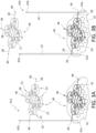
- FIG. 3A shows a simplified apparatus 41a, according to present aspects, for facilitating takeoff (e.g., launching) and landing a VTOL 40, with the VTOL 40 including a vehicle body 22 with at least one of rotor assemblies 23 (shown in FIG. 3A as four rotor assemblies) in communication with the vehicle body 22.
- the VTOL 40 shown in FIGs. 3A and 3B incorporates the enumerated parts shown for VTOL 20 in FIGs. 1 and 2 .
- standoff 28 includes a standoff first end 28a attached to or integral with and outwardly extending from each rotor guard 26.
- Each standoff 28 further comprises a standoff second end 28b terminating in a second cooperating stabilizer element 29.
- second cooperating stabilizer element 49 of standoff 28 is configured to attach to a vertically-oriented support element 42 in an apparatus 41a, as shown in FIG. 3A , with the vertically-oriented support element 42 having a vertically-oriented support element first end 42a, and a vertically-oriented support element second end 42b.
- Vertically-oriented support element 42 appears in FIG. 3A as a single element that can be, for example, a pole anchored to or otherwise in communication with a base (not shown) that can be, for example, the ground or a fixture in contact with the ground 16 at, or proximate to, ground level.
- the term vertically-oriented support element does not necessarily dictate that the pole is purely vertical.
- the pole or vertically-oriented support element is at least a 45 degree angle from the base or ground where the VTOL could land or take off at an angle.
- the pole or vertically-oriented support element is almost horizontal (e.g., about 1 degree from horizontal) and emanates from the side of a building, where the VTOL could land or take off sideways from the building.
- the vertically-oriented support element is curved or in other ways non-linear. Accordingly, the term "vertically-oriented support element" should be construed to comprise a pole or extension to which the VTOL can attach or detach from almost any angle.
- FIG. 3B shows an apparatus 41b, according to aspects not presently being claimed, but useful for understanding aspects of the claimed apparatus, for facilitating takeoff (e.g., launching) and landing a VTOL 40, with the VTOL 40 including a vehicle body 22 with a plurality of rotor assemblies 23 (shown in FIG. 3A as four rotor assemblies) in communication with the vehicle body 22.
- One of the two second cooperating stabilizer elements 49 of one of the two standoffs 28 are configured to attach to a vertically-oriented support element 42 in an apparatus 41b, as shown in FIG. 3B , with the vertically-oriented support element having a vertically-oriented support element first end 42a, and a vertically-oriented support element second end 42b.
- Vertically-oriented support elements 42 appears in FIG. 3B as two elements that can be, for example, two poles anchored to or otherwise in communication with a base (not shown) that can be, for example, the ground or a fixture in contact with the ground 16 (e.g., a base) at, or proximate to, e.g., ground level.
- the second cooperating stabilizer element 49 of the VTOL standoff 28 engages the top of the vertically-oriented support element 42 of, for example, apparatus 41a, 41b.
- the VTOL can then descend, and while ground effect is experienced during the descent of the VTOL to ground level, the turbulent energy 43 from the ground effect (represented by the arrows in FIGs. 3A and 3B ) is transferred from the VTOL to the vertically-oriented support element such that the VTOL descent is significantly stabilized as the ground effect on the VTOL is significantly minimized or eliminated.
- the vertically-oriented support elements 42 of apparatus 41a, 41b can be anchored into the ground 16, or can be attached or otherwise in fixed communication with a base that is in communication with the ground, or a structure that can be, for example, proximate to the ground.
- the term "vertically-oriented support element” does not necessarily dictate that the poles or vertically-oriented support elements are purely vertical. In some aspects the poles or vertically-oriented support elements are at least a 45 degree angle from the base or ground wherein the VTOL could land into them or take off from them at an angle. In some aspects not presently being claimed, but useful for understanding aspects of the claimed apparatus, the poles or vertically-oriented support elements are almost horizontal (e.g., about 1 degree from horizontal) and emanate from the side of a building, where the VTOL could land or take off sideways or nearly horizontally from the building. In some aspects, the vertically-oriented support elements are curved or in other ways non-straight, although they would generally be in parallel. Accordingly, the term “vertically-oriented support element” should be construed to comprise poles or extensions, or members to which the VTOL can attach or detach from almost any angle to support and/or stabilize the VTOL.
- the standoffs integral with or attached to the VTOLs can comprise the "male" second cooperating stabilizer element at the terminus of the second end of the standoff, with the selection made according to the selected features incorporated into, attached to or integral with the vertically-oriented support element of the present apparatuses. That is, the first cooperating stabilizer element on the vertically-oriented support element and the second cooperating stabilizer element of the VTOL standoff are selected to "mate" or interlock.
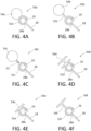
- FIGs. 4A-4F are representative and enlarged overhead or "top” views of assemblies 50a, 50b, 50c, 50d, 50e, and 50f of engaged first and second cooperating stabilizer elements, with the varying first cooperating stabilizer elements 52a, 52,b, 52c, 52d, 52e, 52f (shown in FIGs. 4A, 4B, 4C, 4D, 4E, 4F respectively) integral with or attached to, or otherwise in communication with, the vertically-oriented support element 54a, 54b, 54c, 54d, 54e, 54f of a VTOL takeoff and landing apparatus and shown as being a type of "female" fixture.
- FIGs. 4A-4F further show an engaged second cooperating stabilizer element of VTOL standoff 28 in communication with or integral with a second cooperating stabilizer element 29 shown as a "male" fixture dimensioned to engage the "female" first cooperating stabilizer element 52a, 52,b, 52c, 52d, 52e, 52f of the associated and corresponding vertically-oriented support element 54a, 54b, 54c, 54d, 54e, 54f.
- 4A - 4F are representative and are non-exhaustive, with additional geometries (including, e.g., cross-sectional geometries, mating geometries, etc.) for the vertically-oriented support element and the first and second cooperating features contemplated by the present aspects.
- FIG. 4A shows an assembly 50a not according to the presently claimed apparatus, with the VTOL standoff 28 in communication with or integral with a second cooperating stabilizer element 29 shown as a "male” fixture dimensioned to engage the "female” first cooperating stabilizer element 52a of the associated vertically-oriented support element 54a.
- FIG. 4B shows an assembly 50b not according to the presently claimed apparatus, with the VTOL standoff 28 in communication with or integral with a second cooperating stabilizer element 29 shown as a "male” fixture dimensioned to engage the "female” first cooperating stabilizer element 52b of the associated vertically-oriented support element 54b.
- FIG. 4A shows an assembly 50a not according to the presently claimed apparatus, with the VTOL standoff 28 in communication with or integral with a second cooperating stabilizer element 29 shown as a "male” fixture dimensioned to engage the "female” first cooperating stabilizer element 52b of the associated vertically-oriented support element 54b.
- FIG. 4C shows an assembly 50c with the VTOL standoff 28 in communication with or integral with a second cooperating stabilizer element 29 shown as a "male" fixture dimensioned to engage the "female" first cooperating stabilizer element 52c of the associated vertically-oriented support element 54c, with a spring element 53 positioned between and in communication with the "female” first cooperating stabilizer element 52c and the associated vertically-oriented support element 54c.
- the spring element 53 represents an element able to flex, absorb and/or dissipate vibrational or other forces that can attend ground effect turbulence, etc.
- the spring element can be, for example, an internal compression spring, a shock absorber, a telescoping extender, etc., and combinations thereof.
- FIG. 4D shows an assembly 50d not according to the presently claimed apparatus, with the VTOL standoff 28 in communication with or integral with a second cooperating stabilizer element 29 shown as a "male” fixture dimensioned to engage the "female” first cooperating stabilizer element 52d of the associated vertically-oriented support element 54d, with the vertically-oriented support element 54d shown as comprising "I" beam configuration.
- FIG. 4E shows an assembly 50e not according to the presently claimed apparatus, with the VTOL standoff 28 in communication with or integral with a second cooperating stabilizer element 29 shown as a "male” fixture dimensioned to engage the "female” first cooperating stabilizer element 52e of the associated vertically-oriented support element 54e.
- FIG. 4D shows an assembly 50d not according to the presently claimed apparatus, with the VTOL standoff 28 in communication with or integral with a second cooperating stabilizer element 29 shown as a "male” fixture dimensioned to engage the "female” first cooperating stabilizer element 52e of the
- FIG. 4F shows an assembly 50f not according to the presently claimed apparatus, with the VTOL standoff 28 in communication with or integral with a second cooperating stabilizer element 29 shown as a "male” fixture dimensioned to engage the "female” first cooperating stabilizer element 52f of the associated vertically-oriented support element 54f.
- the terms “standoff” and “standoff element” are used equivalently and interchangeably herein. Further the terms “standoff first end” and “standoff element first end” are used equivalently and interchangeably herein. In addition, the terms “standoff second end” and “standoff element second end” are used equivalently and interchangeably herein.
- the standoff element protrudes from or is otherwise associated as part of a VTOL structure, the standoff element can be equivalently referred to as a "vehicle standoff element", “vehicle standoff”, or "VTOL standoff".
- the second cooperating stabilizer element 29 extends longitudinally along the length of the associated vertically-oriented support element 54a, 54b, 54c, 54d, 54e, 54f.
- the slot-like function of the first cooperating stabilizer element 52a, 52b, 52c, 52d, 52e, 52f can serve to act as a guide to assist the downward process during landing of the VTOL along the length of the vertically-oriented support element 54a, 54b, 54c, 54d, 54e, 54f down to the ground level.
- FIGs. 4A, 4B, 4C, 4D, and 4F show the vertically-oriented support element 54a, 54b, 54c, 54d, 54e, 54f (e.g., pole) in direct or integral contact with the first cooperating stabilizer element 52a, 52b, 52c, 52d, 52e, 52f.
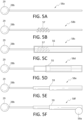
- FIGs. 5A - 5F are illustrations of enlarged side, top, or bottom views of standoffs that can be integrated into or can be otherwise in communication with a structure of the VTOL, and that can extend outwardly from a VTOL structure such as, for example, (and as shown in the FIGs.) a rotor guard, etc.
- the FIGs. are exemplary and are not exhaustive relative to the shapes and configurations of the standoffs.
- the standoffs shown in FIGs. 5A, 5B, 5C, 5D, 5E, and 5F are substantially linear, e.g., following a single axis along their length, the standoffs, according to present aspects, can angularly deviate from a linear orientation.
- second cooperating stabilizer element 29 can comprise a solid object of a different shape.
- second cooperating stabilizer element 29 can comprise a circular object that rotates or rolls (e.g., like a wheel, roller, or bearing) inside the female first cooperating stabilizer element of the vertically-oriented element.
- the second cooperating stabilizer element 29 and/or inner surfaces of the first cooperating stabilizer element 52a, 52b, 52c, 52d, 52e, 52f can comprise a low friction coefficient material or material coating, such as, for example polytetrafluoroethylene (PTFE) to facilitate relative movement of the second cooperating stabilizer element 29 along and within the length of the first cooperating stabilizer element 52a, 52b, 52c, 52d, 52e, 52f.
- PTFE polytetrafluoroethylene
- FIG. 5A shows standoff 58a comprising a standoff second end 28b terminating in a second cooperating stabilizer element 29 having a "male" configuration for engagement with a female first cooperating stabilizer element on a vertically- oriented element of the type shown, for example, in FIGs. 4A-4F .
- FIG. 5A shows standoff 58a comprising a standoff second end 28b terminating in a second cooperating stabilizer element 29 having a "male" configuration for engagement with a female first cooperating stabilizer element on a vertically- oriented element of the type shown, for example, in FIGs. 4A-4F .
- standoff 58b comprising a standoff second end 28b terminating in a second cooperating stabilizer element 29 having a "male" configuration for engagement with a female first cooperating stabilizer element
- standoff 58b comprising a standoff second end 28b terminating in a second cooperating stabilizer element 29 having a "male” configuration for engagement with a female first cooperating stabilizer element
- standoff 58b further comprising a spring element 57 that can dissipate vibrational and other forces including for example, impact, contact, etc., that can occur during VTOL landing and takeoff, according to present aspects.
- the addition of the spring element 57 can contribute to the performance of the present apparatuses, systems, and methods by further stabilizing a VTOL during takeoff and landing, etc.
- FIG. 5C shows standoff 58c comprising a standoff second end 28b terminating in a second cooperating stabilizer element 29 having a "male" configuration for engagement with a female first cooperating stabilizer element, with standoff 58c further comprising a spring element 57 disposed within a spring housing 56.
- FIG. 5D shows standoff 58d comprising a standoff second end 28b terminating in a second cooperating stabilizer element 29 having a "male" configuration for engagement with a female first cooperating stabilizer element, with standoff 58d further comprising a shock absorber 55 that can dissipate vibrational and other forces including for example, impact, contact, etc., that can occur during VTOL landing and takeoff, according to present aspects.
- FIG. 5E shows standoff 58e comprising a standoff second end 28b terminating in a second cooperating stabilizer element 29 having a "male" configuration for engagement with a female first cooperating stabilizer element, with standoff 58e further comprising a telescoping section 59 that can be adjusted to alter the length of the standoff to tailor a VTOL for use with present landing and takeoff apparatuses having varying dimensions and/or varying distances between vertically-oriented support elements (e.g., to which the VTOL standoffs will engage during takeoff and landing, etc.).
- FIG. 5F shows standoff 58f comprising a standoff second end 28b terminating in a second cooperating stabilizer element 29 having a "male" configuration for engagement with a female first cooperating stabilizer element, with standoff 58f further comprising a telescoping section 59 that is in communication with a telescoping section motor 59a that can be actuated (e.g., remotely, in real time, while the VTOL is in flight, etc.) to alter the length or otherwise adjust the standoff to further tailor and enhance the versatility and compatibility of a VTOL for use with present landing and takeoff apparatuses having varying dimensions and/or varying distances between vertically-oriented support elements (e.g., to which the VTOL standoffs will engage during takeoff and landing, etc.).
- a telescoping section 59 that is in communication with a telescoping section motor 59a that can be actuated (e.g., remotely, in real time, while the VTOL is in flight, etc.)
- FIGs. 6A-6E are representative overhead enlarged views of assemblies 60a, 60b, 60c, 60d, and 60e of engaged first and second cooperating stabilizer elements not according to the presently claimed apparatus, with the varying first cooperating stabilizer elements 62a, 62b, 62c, 62d, 62e (shown in FIGs. 6A, 6B, 6C, 6D, 6E , respectively) integral with or attached to, or otherwise in communication with, the vertically-oriented support element 64a, 64b, 64c, 64d, 64e of a VTOL takeoff and landing apparatus.
- the first cooperating stabilizer elements 62a, 62b, 62c, 62d, 62e are shown as being a type of "male" fixture.
- 6A-6F further show an engaged second cooperating stabilizer element of VTOL standoff 28 in communication with or integral with a second cooperating stabilizer element 69 shown as a "female" fixture dimensioned to engage the "male" first cooperating stabilizer element 62a, 62,b, 62c, 62d, 62e of the associated and corresponding vertically-oriented support element 64a, 64b, 64c, 64d, 64e, 64f.
- further enhancements may be added to increase the ability of the cooperating stabilizer elements to roll or slide within each other, such as ball bearings, wheels, rollers, lubricants, etc.
- FIG. 6A shows an assembly 60a with the VTOL standoff 28 in communication with or integral with a second cooperating stabilizer element 29 shown as a "female” fixture dimensioned to engage the "male” first cooperating stabilizer element 62a of the associated vertically-oriented support element 64a.
- FIG. 6B shows an assembly 60b with the VTOL standoff 28 in communication with or integral with a second cooperating stabilizer element 29 shown as a "female” fixture dimensioned to engage the "male” first cooperating stabilizer element 62b of the associated vertically-oriented support element 64b.
- FIG. 6A shows an assembly 60a with the VTOL standoff 28 in communication with or integral with a second cooperating stabilizer element 29 shown as a "female” fixture dimensioned to engage the "male” first cooperating stabilizer element 62b of the associated vertically-oriented support element 64b.
- FIG. 6C shows an assembly 60c with the VTOL standoff 28 in communication with or integral with a second cooperating stabilizer element 29 shown as a "female" fixture dimensioned to engage the "male" first cooperating stabilizer element 62c of the associated vertically-oriented support element 64c, with a spring element 63 positioned between and in communication with the "male” first cooperating stabilizer element 62c and the associated vertically-oriented support element 64c.
- the sprint element 63 represents an element able to absorb or dissipate vibrational or other forces that can attend ground effect turbulence, etc.
- the spring element can be, for example, an internal compression spring, a shock absorber, a telescoping extender, etc., and combinations thereof.
- FIG. 6D shows an assembly 60d with the VTOL standoff 28 in communication with or integral with a second cooperating stabilizer element 29 shown as a "female” fixture dimensioned to engage the "male" first cooperating stabilizer element 62d of the associated vertically-oriented support element 64d, with the vertically-oriented support element 64d shown as comprising "I" beam configuration.
- FIG. 6E shows an assembly 60e with the VTOL standoff 28 in communication with or integral with a second cooperating stabilizer element 29 shown as a "female” fixture dimensioned to engage the "male” first cooperating stabilizer element 62e of the associated vertically-oriented support element 64e.
- the first cooperating stabilizer element can extend outwardly from and be integral with the vertically-oriented support element.
- the slot-like function of the second cooperating stabilizer element can serve to act as a guide to assist the downward process during landing of the VTOL along the length of the vertically-oriented support element down to the ground level.
- the geometry of the first cooperating stabilizer element of the vertically-oriented support element comprises a "female" configuration and the second cooperating stabilizer element of the VTOL standoff can comprise a "male" configuration such that the first and second cooperating stabilizer elements can engage together to form a connected orientation and impart stabilizing characteristics to the VTOL during ascent (e.g., takeoff) from and descent (e.g., landing) onto the presently disclosed support apparatuses.
- FIGs. 7A-7F illustrate enlarged views of standoffs 58a, 58b, 58c, 58d, 58e, 58f similar to those depicted in FIGs. 5A-5F , but with the second cooperating stabilizer element 69 located at the terminus of the standoff second end 28b of the standoffs shown now comprising a "female" second cooperating stabilizer element configuration (rather than the "male” configuration of the second cooperating stabilizer element 29 as shown in FIGs. 5A-5F ).
- the standoffs 28 are configured to dissipate vibrational and other forces including for example, impact, contact, etc., that can occur during VTOL landing and takeoff, according to present aspects.
- the first and second cooperating stabilizer elements can comprise actuators and mechanisms to achieve a degree of movement in the cooperating stabilizer elements to facilitate engagement of the first and second cooperating stabilizer elements, including movement in real-time and in response to a signal (e.g., movement of the cooperating stabilizer element having the "female" configuration to facility entry and engagement of the cooperating stabilizer element having the "male” configuration).
- FIGs. 8A-8C show a progression of a second cooperating stabilizer element of a standoff during, for example, a landing operation of a VTOL.
- a standoff 28 has a second cooperating stabilizer element 69 located proximate to the standoff second end 28b, with the second cooperating stabilizer element 69 shown as being actuated to an "open" orientation, (e.g., in anticipation of the VTOL approaching the first cooperating stabilizer element of a vertically-oriented support element during a landing maneuver).
- the second cooperating stabilizer element 69 of standoff 28 is shown as having moved to a "partially closed” orientation (compared to the "open" orientation shown in FIG. 8A ).
- FIG. 8C shows the second cooperating stabilizer element 69 of standoff 28 in a "closed” orientation.
- signals e.g. signals sent to the VTOL including signals sent remotely to the VTOL, signals sent from the VTOL itself, etc. to actuation devices, etc.
- signals are sent to and received by the VTOL to actuate the second cooperating stabilizer element of the standoff to open or expand a second cooperating stabilizer element "female" fixture to facilitate engagement of the second cooperating stabilizer element to a first cooperating stabilizer element on the vertically-oriented support element of the landing (and takeoff) apparatus presented herein.
- the second cooperating stabilizer element 69 shown in FIGs. 8A-8C can be in the form of adjustable grasping tips further comprising motors on the tips or the tips can be in communication with mechanical attachments and linkages located on or within the standoff structure that can include, for example, solenoids to perform "grasping", and that can be responsible for operating the tips to open and/or close to varying and selected degrees.
- motors, mechanical linkages, wires, etc. can be located in the VTOL, with the VTOL-located motors in communication with the grasping tips, etc.
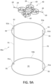
- FIGs. 9A-9C illustrate, according to aspects not presently being claimed, but useful for understanding aspects of the claimed apparatus, a VTOL engaged in a landing operation, with the VTOL descending and coming into proximity with a VTOL landing and takeoff stabilizing apparatus. As shown in FIG.
- the VTOL is oriented during landing such that two of the standoffs 28 on the VTOL 40 are moved into a position proximate to first cooperating stabilizer elements 92 located at the vertically-oriented support element second ends 91b of the vertically-oriented support elements 91 to place a second cooperating stabilizer element 69 of a standoff 28 in position to engage the first cooperating stabilizer element 92 located at the second end 91b of a vertically-oriented support element 91.
- FIG. 9A further shows a circumferential frame support 93a engaging the two vertically-oriented support elements 91 proximate to the two vertically-oriented support element second ends 91b, and further shows a circumferential frame support 93b engaging the two vertically-oriented support elements 91 proximate to the two vertically-oriented support element first ends 91a. While the engagement can be a direct engagement, as shown in FIGs. 9A-9C the circumferential frames 93a, 93b are shown engaging a frame standaway attachment 95 that in turn engages or is otherwise in communication with the two vertically-oriented support element first ends 91a and vertically-oriented support element second ends 91b.
- circumferential frame support 93a and 93b as shown are circular, however any shape of frame support that maintains the form and/or shape of the vertical takeoff and landing stabilizing apparatus is acceptable.
- the VTOL takeoff and landing stabilizing apparatus is attached directly to the ground or some other structure.
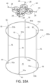
- FIGs 10A-10C depict a VTOL engaged in a landing operation similar to that shown in FIGs. 9A-9C , with the VTOL 40 descending and coming into proximity with a VTOL landing and takeoff stabilizing apparatus 100a, 100b having four vertically-oriented support elements 91. As shown in FIG.
- a VTOL 40 approaches a VTOL landing and takeoff stabilizing apparatus 100a, and the VTOL 40 is oriented during landing such that four of the standoffs 28 on the VTOL 40 are moved into an aligned position proximate to first cooperating stabilizer elements 92 located at the second ends 92b of the four vertically-oriented support elements 91 and in a relative position between the VTOL 40 and the apparatus 100a to place a second cooperating stabilizer element 69 of a standoff 28 in position to engage the first cooperating stabilizer element 92 located at the second end 91b of a vertically-oriented support element 91.
- 10A further shows a circumferential frame support 93a engaging the four vertically-oriented support elements 91 proximate to the four vertically-oriented support element second ends 91b, and further shows a circumferential frame support 93b engaging the four vertically-oriented support elements 91 proximate to the four vertically-oriented support element first ends 91a.
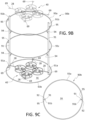
- FIG. 10B shows a landing apparatus 100b, similar to the VTOL landing apparatus 100a (shown in FIG. 10A ), with apparatus 90b showing an additional circumferential frame support 93c located approximately midway between circumferential frame supports 93a and 93b, and apparatus 100b is shown at least for the purpose of connoting that any number of circumferential frame supports can be included and present in the presently contemplated apparatuses. While FIG. 10B does not show further reinforcements in contact with the circumferential frame supports 93a, 93b, 93c and the vertically-oriented support elements 91, the inclusion of additional supports of the type shown in FIGs. 9A-9C are contemplated for apparatuses 100a, 100b.
- the VTOL shown in FIG. 10B in "broken lines" represents a VTOL that is in the process of landing, with the VTOL located on the ground 16 having completed a landing is shown and drawn in solid lines.
- FIG. 10C is an overhead view of the VTOL takeoff and landing apparatus 100b shown in FIG. 10B with numbered features as indicated in FIG. 10B .
- the apparatuses 100a, 100b shown in FIGs. 10A-10C facilitate the landing and takeoff of VTOLs by increasing the stability of a VTOL during takeoff and landing, and by significantly ameliorating and/or eliminating ground effect turbulence, turbulent rotation of the VTOL by ground effect, and such present apparatuses facilitate the dissipation of recirculating vortices otherwise caused by ground effect, with turbulent energy and effects transferred from the VTOL to the apparatuses of the types shown in FIGs. 10A-10C . While FIGs. 10A-10C show four vertically-oriented support elements, present aspects contemplate including a selected number of vertically-oriented support elements other than four.
- methods, systems, and apparatuses employing the presently disclosed VTOL takeoff and landing apparatuses can include a platform to further enhance the stability imparted to a VTOL engaged in a landing or takeoff operation.
- the platform can comprise a grate made from a material that can be a rigid or taut material, including a mesh material that can be a rigid mesh material, and having an average mesh gauge, such that the grate comprises a mesh material selected to be robust enough to support the weight of a VTOL that comes in contact with the grate, and that is supported by the grate.
- FIG. 11A shows a VTOL 40 having completed a landing operation, onto apparatus 110 not presently being claimed, but useful for understanding aspects of the claimed apparatus, with the VTOL in position on a platform 112.
- platform 112 is made from a rigid and/or taut material.
- the platform is constructed to form a platform suitable to support the weight of the VTOL 40, with the rigid material configured into a grid or mesh such that airflow from the VTOL 40, at least during landing, passes through the platform at a rate and to a degree that substantially no ground effect is directed from the platform toward the VTOL 40, and the platform does not otherwise negatively impact the stability afforded the VTOL by the apparatus 112, at least during landing.
- a platform 112 that can be made from metals, plastics, resin-based composite materials, ceramics, cloth, and combinations thereof.
- the platform can be made from a conductive material, or can be coated or impregnated with a conductive material or a conductive material coating, etc.
- VTOL 40 comprises a plurality of standoffs 28 (shown in FIG. 11A as four standoffs 28) and with a second cooperating stabilizer element 29, 69 located proximate to the terminus of vertically-oriented support element 91 second end 91b.
- the four second cooperating stabilizer elements 69 associated with the four VTOL standoffs 28 have engaged the four first cooperating stabilizer elements 92 that are in communication with the four vertically-oriented support elements 91.
- FIG. 11A further shows a circumferential frame support 93b engaging the four vertically-oriented support elements 91 proximate to the four vertically-oriented support element first ends 91a and further proximate to the ground 16.
- circumferential frame support 93b is shown as circular, however any shape of frame support that maintains the form and/or shape of the vertical takeoff and landing stabilizing apparatus is acceptable.
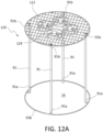
- FIGs. 12A , 12B, and 12C show alternate arrangement for a VTOL takeoff and landing stabilizing apparatus 120 that allows for an absence of first cooperating stabilizer elements on the vertically-oriented support element first end, and further allows for assisting and facilitating the takeoff and landing of VTOLs that do not comprise standoffs extending from the VTOL, such as, for example, standoffs extending from a rotor guard.
- FIG. 12A shows a VTOL 124 resting on apparatus 120 comprising elements similar to those shown in FIGs 11A-11C and described herein, with the exception that apparatus 120 comprises a platform 112, that can be a grid/mesh platform, with the platform 112 further comprising at least one retainer 122 in communication with the platform 112, with the retainer 122 configured to releasably engage a structure of a VTOL (e.g., a VTOL landing strut, landing skid, wheel, etc.) during a VTOL landing, resting, and/or a takeoff operation.
- FIG. 12A further shows a VTOL in contact with platform 112.
- FIG. 12A also shows vertically-oriented support elements 91 having vertically-oriented support element second ends 91b that can be substantially flush with, and that may not extend beyond the upper surface of the platform.
- FIG. 12A shows a VTOL 124 that does not comprise standoffs extending from any rotor guard and otherwise configured to engage any structure of apparatus 120.
- FIG. 12B is an overhead or top view of the apparatus 120 shown in FIG. 12A , wherein the VTOL 124 (also shown in a side view in FIG. 12C ) is positioned proximate to the platform 112, with platform 112 comprising a retainer 122 configured to engage landing skid 128 of VTOL 120.
- retainers can also, or in an alternative, extend from a VTOL structure (e.g. landing skid, etc.) and be configured to securely and releasably engage the grid mesh of platform 112.
- retainers 122 can be associated and/or in communication with apparatus 120, and, if one or more retainers (not shown) are integral with the VTOL, motors, actuators, electronics, signaling transmitter and receivers, mechanical mechanisms, etc., can be located on the VTOL to control movement of retainers, including movement configured to releasable engage such retainers on the VTOL with a platform of the type shown in FIGs. 12A , 12B .
- FIG. 12C is a side view of the apparatus 120 shown in FIG. 12A , wherein the VTOL 124 (also shown in a side view) is positioned proximate to the platform 112, with platform 112 comprising a retainer 122 configured to engage landing skid 128 of VTOL 124.
- retainers can also or in the alternative extend from a VTOL structure (e.g. landing skid, etc.) and be configured to securely and releasably engage the grid mesh of platform 112.
- motors, actuators, electronics, signaling transmitter and receivers, mechanical mechanisms, etc., to impart a degree of movement for one or more retainers 122 can be associated and/or in communication with apparatus 120, and, if one or more retainers (not shown) are integral with the VTOL, motors, actuators, electronics, signaling transmitter and receivers, mechanical mechanisms, etc., can be located on the VTOL to control movement of retainers, including movement configured to releasably engage such retainers on the VTOL with a platform of the type shown in FIGs. 12A , 12B, and 12C .
- a platform of the type shown in FIGs. 11A, 11B , 11C and/or FIGs. 12A , 12B, and 12C can further comprise mechanical mechanisms to actuate movement of a platform of the types described herein.
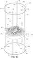
- a VTOL takeoff and landing apparatus 130 not presently being claimed, but useful for understanding aspects of the claimed apparatus, can combine aspects of the apparatuses shown at least in FIGs. 11A-11C, 12A , 12B, 12C and can further include a platform configured to move or migrate through various selected vertical positions and locations longitudinally along the length of the vertically-oriented support elements of the disclosed VTOL takeoff and landing apparatuses described herein.
- VTOL 40 comprising standoffs 28 terminating in a second cooperating stabilizer element 69 is shown in prior to a takeoff operation or is shown at the completion of a landing operation such that each of the VTOL's second cooperating stabilizer element 69 is engaged with a vertically-oriented support element 91.
- VTOL 40 is shown resting on horizontally-disposed platform 112 with destabilizing ground effect on the VTOL (generated by the VTOL rotors during takeoff and/or landing) significantly ameliorated or substantially eliminated by transferring energy and forces from, for example, ground effect, at least in part, to the stabilizing apparatus 130.
- power e.g., electrical power
- the drive mechanism 134 can (as shown in FIG. 13 ) located in direct communication, or otherwise integral with, horizontally-disposed platform 112.
- at least portions of the drive mechanism can be located remotely from, but in communication with, drive elements located in communication with platform 112.
- the platform 112 can be moved (e.g., lowered, raised, etc.) to a desired height, including ground level.
- the drive mechanism can be located remotely from but in communication with platform 112 with the drive mechanism configured to ascend or descend the platform 112 to varying selected heights along the length of the apparatus 130.
- the VTOL 40 can be positioned on platform 112 with second cooperating stabilizer elements 69 on standoffs 28 engaged (e.g., one each) to a vertically-oriented support element 91. If takeoff from a height other than ground level is desired, the platform can be directed to a selected height along the length of the apparatus 130 up to and including a height such that the platform is proximate to the maximum height of the apparatus with the platform driven to a height occupied proximate to the vertically-oriented support element second ends 91b. The VTOL can then be activated for takeoff, with significantly enhanced VTOL takeoff stability as the undesirable takeoff ground effects are significantly ameliorated and/or significantly eliminated.
- VTOL VTOL landing protocol
- power e.g., electrical power
- a drive mechanism 134 to elevate platform 112 to a selected height within apparatus 130 to receive the landing VTOL in a stabilized landing with ameliorated or eliminated ground effect.
- the VTOL is guided to align second cooperating stabilizer elements 69 on the VTOL standoffs 28 with first cooperating stabilizer elements 92 located integral with or proximate to the vertically-oriented support elements 91 of apparatus 130.
- the VTOL 40 When the controlled and stabilized landing is completed, the VTOL 40 will safely rest on platform 112, at which point, in the landing protocol, the drive mechanism 134 in platform 112 can be activated manually or automatically to cause the platform to descend from, for example, a selected platform landing height, to a selected platform 112 height that can include, for example, ground level.
- present apparatuses disclosed herein can further include guides that can be attached to, in communication with, or otherwise located proximate to the vertically-oriented support element second ends 91b of the present apparatuses.
- FIGs. 14A, 14B, 14C , 15A, 15B , 16A, 16B show exemplary variations not presently being claimed, but useful for understanding aspects of guides according to present aspects, that can be configured to further stabilize VTOL takeoff and landing and incorporated into the apparatuses, systems, and methods disclosed herein.
- the guides can be incorporated into any of the presently disclosed VTOL takeoff and landing apparatuses, systems, and methods.
- VTOL takeoff and landing apparatus 140 comprises many of the features presented in the present apparatuses, including, for example, the apparatus 100a shown in FIG. 10A .
- guide 142 "tops" apparatus 140, with guide first end 142a contacting or otherwise located proximate to the vertically-oriented support element second end 141c, and with guide first end 142a having a guide first end diameter (d1) (see FIG. 14C ) that can be substantially equivalent to the diameter of the circumferential frame support 93a.
- Guide 142 further comprises a guide second end 142b having a guide second end diameter (d2) (see FIG. 14C ), with the guide second end diameter (d2) being greater than the guide first end diameter (d1). See side view of guide 140 at FIG. 14C , showing guide second end diameter (d2), being greater than the guide first end diameter (d1).
- FIG. 14B is an overhead view of VTOL takeoff and landing apparatus 140 showing guide first end 142a and guide second end 142b, with VTOL 20 "nested" within guide 140, with VTOL 20 engaged in a landing or a takeoff protocol.
- the parts shown in FIGs 14A and 14B are as labelled for apparatus 100a in FIG. 10A , but the guide 142 shown in FIGs. 14A-14C is understood as being adaptable to the many apparatuses disclosed herein.
- the guide 142 as shown in FIG. 14A can comprise guide first end 142a and guide second end 142b that, geometrically, are also substantially circular.
- the guide can have an overall geometry that is frustoconical.
- the guide geometry may "match" a geometry near the opening of the VTOL takeoff and landing apparatus that is located adjacent to the guide first end 142a.
- the general geometry of the guide 142 is circular, and the general geometry of the apparatus 140 is tubular and also cross-sectionally generally circular.
- a guide inner surface 142c of guide 142 can incorporate raised elements or elements in relief that serve as "grooves" or guide inner surface channels 142d (e.g., guide inner surface channels configured to form a directional track, etc.) that are shown in FIGs. 14A, 14B, 14C , with the guide shown to be conical and "funnel-like" in shape.
- the guide inner surface channels 142d can be in communication with, and can be in general alignment with, the first cooperating stabilizer elements, and the groves can facilitate the directing of the VTOL from a position within the guide to the first cooperating stabilizer elements by feeding at least one of the VTOL second cooperating stabilizer elements from the guide inner surface channel 142d to the first cooperating stabilizer element in communication with the vertically-oriented support element of the VTOL takeoff and landing apparatus.
- the first cooperating stabilizing element can comprise grooves or raised features configured to form a "directional track" or “directional channel” in the guide inner surface, such that the directional track can be dimensioned to accommodate the dimension of the second cooperating stabilizer element of the standoff.
- the second cooperating stabilizer element of the VTOL standoff engages, or otherwise comes into contact with, the directional track in the guide inner surface
- the second cooperating stabilizer element (and the VTOL that is attached to the second cooperating stabilizer element) is directed from the guide downward into the first cooperating stabilizer element that comprises the track or channel.
- a landing protocol provided for VTOLs is further facilitated.
- a VTOL 20 can approach an area proximate to the top of the guide 142 and the VTOL can further be substantially centered in flight to hover over the guide.
- the second cooperating stabilizing element 29 at the outer terminus of the standoff 28 can associate with and otherwise become at least partially inserted into, grooves configured to form a directional track or directional channel that "feeds" into internal tracks along the inner surface of the guide 142.
- the outer and/or inner geometry of the VTOL takeoff and landing apparatus need not be substantially circular, substantially tubular, substantially cylindrical, etc., so long as the internal lengthwise dimension of the VTOL takeoff and landing apparatus can dimensionally accommodate the outer dimension of a VTOL designed to takeoff from or land into a particular VTOL takeoff and landing apparatus.
- FIGs. 15A, 15B , 16A, 16B depict further exemplary and non-exhaustive configurations for contemplated VTOL takeoff and landing apparatuses not presently being claimed, but useful for understanding aspects of the claimed apparatus
- the overall geometries e.g. substantially rectangular or "square" of the apparatus longitudinal "body” or “chute” is shown as matching a geometry of the guide, and it is understood that, according to present aspects not shown, guide geometries can differ from apparatus body or "chute" geometries, so long as the internal lengthwise dimension of the VTOL takeoff and landing apparatus can dimensionally accommodate the outer dimension of a VTOL designed to takeoff from or land into a particular VTOL takeoff and landing apparatus.
- FIGs. 15A and 15B show a VTOL takeoff and landing apparatus 150 comprising a guide 152 that can "top" apparatus 150, with guide first end 152a contacting or otherwise located proximate to the vertically-oriented support element second end 151b, and with guide first end 152a having a guide first end width (w1) that can be substantially equivalent to the diameter of a circumferential frame support.
- Guide 152 further comprises a guide second end 152b having a guide second end width (w2), with the guide second end width (w2) being greater than the guide first end width (w1).
- a guide inner surface 152c of guide 152 can incorporate raised elements or elements in relief that serve as "grooves" or guide inner surface channels 152d that are shown in FIGs. 15A, 15B .
- the guide inner surface channel 152d can be formed by the grooves, recesses, regions of raised relief, etc. that can be oriented along the guide inner surface 152c of guide 152 with the guide inner surface channel 152d in communication with, substantially aligned with, and otherwise feeding into the vertically-oriented support element channel 151c on the vertically-oriented support element 151.
- FIG. 15B is an overhead view of VTOL takeoff and landing apparatus 150 showing guide first end 152a and guide second end 152b, with VTOL 20 "nested" within guide 150, with VTOL 20 engaged in a landing or a takeoff protocol.
- the guide 152 shown in FIGs. 15A, 15B is understood as being adaptable to the many apparatuses disclosed herein.
- FIGs. 16A and 16B show a VTOL takeoff and landing apparatus 160 comprising a guide 162 that can "top" apparatus 160, with guide first end 162a contacting or otherwise located proximate to the vertically-oriented support element second end 161b, and with guide first end 162a having a guide first end dimension that can be substantially equivalent to a geometry that is collectively formed by the location of the plurality of the vertically-oriented support element second ends 161b, such that the guide first end 162a is supported by the vertically-oriented support element second ends 161b.
- Guide 162 further comprises a guide second end 162b having a guide second end width, with the guide second end width being greater than the guide first end width.
- FIG. 16B is an overhead view of VTOL takeoff and landing apparatus 160 as shown in FIG. 16A , and showing guide first end 162a and guide second end 162b, with VTOL 20 "nested" within guide 160, with VTOL 20 engaged in a landing or a takeoff protocol.
- the guide 162 shown in FIGs. 16A, 16B is understood as being adaptable to the many apparatuses disclosed herein.
- FIGs. 16A, 16B further shows guide 162 as comprising a guide mesh material 164 that can be a rigid or taut mesh material.
- a guide mesh material can be selected such that, at least during VTOL takeoff and landing, as the VTOL enters the mesh guide, airflow from the VTOL rotors passes through the guide mesh at a rate and to a degree such that substantially no ground effect is directed from the guide surfaces back toward the VTOL 20, and the guide does not otherwise negatively impact the stability afforded the VTOL 20 by the guide 162, at least during VTOL takeoff and landing.
- a highly perforated material can be used as the material for the guide 162.
- a guide 142, 152, 162 that can be made from metals, plastics, resin-based composite materials, ceramics, cloth, and combinations thereof.
- the guide can be made from a conductive material, or can be coated or impregnated with a conductive material or a conductive material coating, etc.
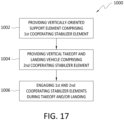
- FIG. 17 , 18 , 19 , and 20 are flowcharts outlining methods according to aspects not presently being claimed, but which can be carried out with the claimed apparatus.
- a method 1000 is outlined for launching and landing a vertical takeoff and landing vehicle is disclosed, with the method 1000 including providing 1002 a vertically-oriented support element, with the vertically-oriented support element having a first end and a second end, with the vertically-oriented support element first end proximate to a base, with the vertically-oriented support element extending from the vertically-oriented support element first end to the vertically-oriented support element second end, with the vertically-oriented support element second end located at a selected distance away from the vertically-oriented support element first end, with the vertically-oriented support element comprising a first cooperating stabilizer element, and with the first cooperating stabilizer element located proximate to the vertically-oriented support element second end.
- the method 1000 further includes providing 1004 a vertical takeoff and landing vehicle, with the vertical takeoff and landing vehicle comprising at least one second cooperating stabilizer element, with the second cooperating stabilizer element dimensioned to engage with the first cooperating stabilizer element, and engaging 1006 the first cooperating stabilizer element of the vertically-oriented support element with the second cooperating stabilizer element of the vertical takeoff and landing vehicle.
- FIG. 18 is a flowchart comprising elements of the method 1000 set forth in FIG. 17 for launching and landing a vertical takeoff and landing vehicle, with the method 1100 of FIG. 18 further comprising stabilizing 1102 the vertical takeoff and landing vehicle during at least one of takeoff and landing.
- FIG. 19 is a flowchart comprising elements of the method 1000 set forth in FIG. 17 for launching and landing a vertical takeoff and landing vehicle, with the method 1200 shown in FIG. 19 further comprising restricting 1202 angular and/or lateral movement of the vertical takeoff and landing vehicle toward and away from the vertically-oriented support element during takeoff and landing of the vertical takeoff and landing vehicle.
- FIG. 20 is a flowchart comprising elements of the method 1000 set forth in FIG. 17 for launching and landing a vertical takeoff and landing vehicle, with the method 1300 further comprising substantially eliminating 1302 impact of ground effect on a VTOL at least during takeoff and landing, and transferring energy and forces created from ground effect to the VTOL takeoff and landing apparatuses of the present disclosure.
Landscapes
- Engineering & Computer Science (AREA)
- Aviation & Aerospace Engineering (AREA)
- Mechanical Engineering (AREA)
- Chemical & Material Sciences (AREA)
- Combustion & Propulsion (AREA)
- Remote Sensing (AREA)
- Current-Collector Devices For Electrically Propelled Vehicles (AREA)
- Vibration Prevention Devices (AREA)
Claims (6)
- Appareil (32, 41a, 41b, 90a, 90b, 100a, 100b, 110, 120, 130, 140, 150, 160) permettant de stabiliser le lancement et l'atterrissage d'un véhicule à décollage et atterrissage verticaux, l'appareil comprenant :
un élément de support orienté verticalement (42, 91, 141, 151, 161), ledit élément de support orienté verticalement comprenant :une première extrémité d'élément de support orienté verticalement (42a, 91a, 141a, 151a, 161a) ; etune seconde extrémité d'élément de support orienté verticalement (42b, 91b, 141b, 151b, 161b, 171b, 181b), ledit élément de support orienté verticalement s'étendant de la première extrémité d'élément de support orienté verticalement à la seconde extrémité d'élément de support orienté verticalement, ladite seconde extrémité étant située à une distance sélectionnée à l'écart de la première extrémité d'élément de support orienté verticalement, ledit élément de support orienté verticalement comprenant au moins un premier élément stabilisateur coopérant (42, 52a, 52b, 52c, 52d, 52e, 52f, 64a, 64b, 64c, 64d, 64e, 92), ledit au moins un premier élément stabilisateur coopérant étant situé à proximité de la seconde extrémité d'élément de support orienté verticalement, dans lequel ledit au moins un premier élément stabilisateur coopérant comprend une partie de fixation femelle (52a, 52b, 52c, 52d, 52e, 52f) dimensionnée pour recevoir une seconde partie stabilisatrice coopérante, ledit second élément stabilisateur coopérant comprenant une partie de fixation mâle,dans lequel la partie de fixation femelle comprend une fente, ladite fente étant située au niveau de la seconde extrémité d'élément de support orienté verticalement, ladite fente s'étendant à une distance sélectionnée de la seconde extrémité d'élément de support orienté verticalement, longitudinalement sur la longueur de l'élément de support orienté verticalement, etdans lequel un élément ressort (53) est positionné entre et en communication avec le premier élément stabilisateur coopérant et l'élément de support orienté verticalement. - Appareil selon la revendication 1, dans lequel ladite seconde extrémité d'élément de support orienté verticalement est située à une certaine distance de la première extrémité d'élément de support orienté verticalement, ladite distance allant d'environ 1,22 m (4 pieds) à environ 30,48 m (100 pieds).
- Appareil selon les revendications 1 ou 2, dans lequel l'au moins un premier élément stabilisateur coopérant est conçu pour s'étendre vers l'extérieur à partir de l'élément de support orienté verticalement.
- Appareil selon l'une quelconque des revendications précédentes, dans lequel l'élément ressort (53) représente un élément pouvant fléchir, absorber et/ou dissiper des forces vibratoires ou autres qui peuvent accompagner des turbulences dues à l'effet de sol.
- Appareil selon l'une quelconque des revendications précédentes, dans lequel l'élément ressort (53) est un ressort de compression interne, un amortisseur, un extenseur télescopique, ou une combinaison de ceux-ci.
- Appareil selon l'une quelconque des revendications précédentes, comprenant en outre un guide (142, 152), ledit guide étant en communication avec la seconde extrémité d'élément de support orienté verticalement de l'élément de support orienté verticalement, ledit guide comprenant l'au moins un premier élément stabilisateur coopérant.
Applications Claiming Priority (2)
| Application Number | Priority Date | Filing Date | Title |
|---|---|---|---|
| US202163167164P | 2021-03-29 | 2021-03-29 | |
| US17/588,408 US12116143B2 (en) | 2021-03-29 | 2022-01-31 | Vertical air vehicle takeoff and landing stabilization apparatuses, systems, and methods |
Publications (2)
| Publication Number | Publication Date |
|---|---|
| EP4067229A1 EP4067229A1 (fr) | 2022-10-05 |
| EP4067229B1 true EP4067229B1 (fr) | 2025-05-07 |
Family
ID=80682701
Family Applications (1)
| Application Number | Title | Priority Date | Filing Date |
|---|---|---|---|
| EP22160423.4A Active EP4067229B1 (fr) | 2021-03-29 | 2022-03-07 | Appareils de stabilisation de décollage et d'atterrissage de véhicule aérien vertical |
Country Status (3)
| Country | Link |
|---|---|
| US (1) | US12116143B2 (fr) |
| EP (1) | EP4067229B1 (fr) |
| CN (1) | CN115140299A (fr) |
Families Citing this family (8)
| Publication number | Priority date | Publication date | Assignee | Title |
|---|---|---|---|---|
| US10829245B2 (en) * | 2016-09-27 | 2020-11-10 | Masten Space Systems, Inc. | Apparatus for vehicle launch, recovery, storage and transport |
| JP6731604B2 (ja) * | 2018-03-31 | 2020-07-29 | 中松 義郎 | 高速ドローン等航空機 |
| US12252280B2 (en) * | 2020-01-11 | 2025-03-18 | 10112755 Canada Inc. | Docking station with retractable guide apparatus for unmanned aerial vehicle |
| WO2022070372A1 (fr) * | 2020-09-30 | 2022-04-07 | 日本電信電話株式会社 | Garde-hélice, véhicule de vol et objet en forme de tige |
| GB2607911B (en) * | 2021-06-15 | 2025-03-26 | Urban Air Port Ltd | Aerodrome structure and construction thereof |
| CN215554243U (zh) * | 2021-07-08 | 2022-01-18 | 朱宁 | 一种垂直起降飞行器起降装置 |
| US12572153B1 (en) | 2022-12-15 | 2026-03-10 | Amazon Technologies, Inc. | Route planning for aerial vehicles in indoor spaces |
| US12528608B1 (en) * | 2024-03-18 | 2026-01-20 | Amazon Technologies, Inc. | Docking stations for safely charging aerial vehicles |
Family Cites Families (45)
| Publication number | Priority date | Publication date | Assignee | Title |
|---|---|---|---|---|
| US2225525A (en) | 1938-02-16 | 1940-12-17 | Autogiro Co Of America | Aircraft with rotating airfoils |
| WO1994020741A1 (fr) | 1993-03-02 | 1994-09-15 | Jae Hwan Kim | Systeme generant une puissance, une force de propulsion et une sustentation a l'aide d'un fluide |
| US6464459B2 (en) | 1999-05-21 | 2002-10-15 | Avionic Instruments, Inc. | Lifting platform with energy recovery |
| US6616094B2 (en) | 1999-05-21 | 2003-09-09 | Vortex Holding Company | Lifting platform |
| NO20015844L (no) | 2001-11-30 | 2003-06-02 | Arne Kristiansen | Anordning for å produsere et trykkpotensial over et legeme |
| US20040244633A1 (en) | 2003-05-08 | 2004-12-09 | Witmer Warner H. | Cats-constrained airplane transportation system |
| WO2008065664A2 (fr) | 2006-11-30 | 2008-06-05 | Urban Aeronautics Ltd. | Modes de postes de pilotage et commandes de vol pour véhicules à décollage et atterrissage verticaux à soufflante canalisée |
| CN201023656Y (zh) | 2007-03-02 | 2008-02-20 | 广州天象地效飞行器股份有限公司 | 地效飞行器 |
| US8286909B2 (en) | 2008-02-08 | 2012-10-16 | Stratocomm Corporation | Boundary layer propulsion airship with related system and method |
| KR20100094056A (ko) | 2009-02-18 | 2010-08-26 | 최기남 | 쌍회전 날개식 수직이착륙기 |
| US9745047B2 (en) | 2013-04-17 | 2017-08-29 | Xiaoyi Zhu | Aircraft generating a lift from an interior thereof |
| CN101602404B (zh) | 2009-07-03 | 2013-12-25 | 朱晓义 | 一种新型结构的飞行器 |
| US20110024553A1 (en) | 2009-07-29 | 2011-02-03 | Hanley (China) Limited | Bottom Blade Type Vehicle |
| EP2279944A1 (fr) | 2009-07-31 | 2011-02-02 | Hanley (China) Limited | Plate-forme volante avec un rotor de sustentation |
| US8695919B2 (en) | 2010-11-12 | 2014-04-15 | Sky Sapience Ltd. | Aerial unit and method for elevating payloads |
| CN109319109B (zh) | 2011-03-29 | 2021-01-12 | 郑鹏 | 牵引输能源式涵道旋翼飞吊器及其控制方法 |
| US10427784B2 (en) | 2011-12-05 | 2019-10-01 | Aurora Flight Sciences Corporation | System and method for improving transition lift-fan performance |
| WO2014025444A2 (fr) | 2012-05-21 | 2014-02-13 | Arlton Paul E | Véhicule à ailes tournantes |
| GB2514770B (en) | 2013-06-03 | 2015-08-05 | Lockheed Corp | Launched air vehicle system |
| CN108715223B (zh) | 2014-02-10 | 2021-08-10 | 林月洪 | 一种飞行器动力源 |
| WO2016019978A1 (fr) * | 2014-08-05 | 2016-02-11 | Telecom Italia S.P.A. | Plateforme d'atterrissage pour un véhicule aérien sans pilote |
| US9915956B2 (en) | 2015-01-09 | 2018-03-13 | Workhorse Group Inc. | Package delivery by means of an automated multi-copter UAS/UAV dispatched from a conventional delivery vehicle |
| US20160208742A1 (en) | 2015-01-17 | 2016-07-21 | John Bradley Pande | DiscThruster, pressure thrust based aircraft engine |
| WO2016137982A1 (fr) | 2015-02-24 | 2016-09-01 | Airogistic, L.L.C. | Procédés et appareil pour le lancement et l'atterrissage d'un véhicule aérien sans pilote |
| US10017245B2 (en) | 2015-04-13 | 2018-07-10 | David Geise | Multirotor flying vehicle |
| GB2543816A (en) | 2015-10-30 | 2017-05-03 | Bae Systems Plc | Rotary-wing air vehicle and method and apparatus for launch and recovery thereof |
| US20170175564A1 (en) | 2015-12-16 | 2017-06-22 | Daniel Schlak | Flywheel with Inner Turbine, Intermediate Compressor, and Outer Array of Magnets |
| EP3747764B1 (fr) | 2015-12-18 | 2022-09-28 | Amazon Technologies, Inc. | Traitements de la pale d'hélice pour contrôle du bruit |
| US10926874B2 (en) | 2016-01-15 | 2021-02-23 | Aurora Flight Sciences Corporation | Hybrid propulsion vertical take-off and landing aircraft |
| KR101749863B1 (ko) | 2016-03-11 | 2017-06-22 | 한국항공우주연구원 | 수직 이착륙 비행체 |
| IL246358A0 (en) | 2016-06-20 | 2016-11-30 | Fox Yuval | A system for positioning and locking and a method for driverless vehicles |
| US10627524B2 (en) | 2016-12-06 | 2020-04-21 | At&T Intellectual Property I, L.P. | Method and apparatus for positioning via unmanned aerial vehicles |
| KR101874204B1 (ko) | 2016-12-13 | 2018-07-03 | 한국항공우주연구원 | 드론 착륙 시스템 |
| CN206552260U (zh) | 2017-03-02 | 2017-10-13 | 北京天宇新超航空科技有限公司 | 一种高效垂直起降飞行器 |
| CN207208447U (zh) | 2017-05-16 | 2018-04-10 | 华南理工大学 | 基于双涵道风扇动力系统的可折叠式固定翼垂直起降无人飞行器 |
| CN107176286B (zh) | 2017-05-16 | 2023-08-22 | 华南理工大学 | 基于双涵道风扇动力系统的可折叠式固定翼垂直起降无人飞行器 |
| CN207631474U (zh) | 2017-12-22 | 2018-07-20 | 北京正兴弘业科技有限公司 | 用于垂直起降无人机的矢量气动舵涵道风扇 |
| US10800524B2 (en) * | 2017-12-23 | 2020-10-13 | Moshe Benezra | Scalable drone launcher |
| US11898368B2 (en) * | 2018-06-14 | 2024-02-13 | Wing Aviation Llc | Unmanned aerial vehicle housing including deployable landing pads |
| US10919625B2 (en) * | 2018-07-24 | 2021-02-16 | The Boeing Company | Reconfigurable unmanned aerial vehicles for subsurface sensor deployment |
| US20200290752A1 (en) | 2019-03-11 | 2020-09-17 | Igor M. Kolosiuk | Autonomous hanging storage, docking and charging multipurpose station for an unmanned aerial vehicle |
| DE102020104832A1 (de) | 2019-08-08 | 2021-02-11 | Rosenberger Hochfrequenztechnik Gmbh & Co. Kg | Ladesystem, Ladeeinrichtung, mobiles Gerät und Einführabschnitt für ein mobiles Gerät |
| CN110884660A (zh) | 2019-11-25 | 2020-03-17 | 广州极飞科技有限公司 | 一种无人机系统 |
| US20210387744A1 (en) * | 2020-01-08 | 2021-12-16 | Iron Drone Ltd. | Unmanned aerial vehicle (uav) launching assembly for monitored and stable launching of uavs |
| KR102403431B1 (ko) | 2020-12-17 | 2022-06-02 | 주식회사 드론비즈 | 드론을 이용한 교통관제 시스템 및 방법 |
-
2022
- 2022-01-31 US US17/588,408 patent/US12116143B2/en active Active
- 2022-03-07 EP EP22160423.4A patent/EP4067229B1/fr active Active
- 2022-03-29 CN CN202210318440.6A patent/CN115140299A/zh active Pending
Also Published As
| Publication number | Publication date |
|---|---|
| US20220306319A1 (en) | 2022-09-29 |
| US12116143B2 (en) | 2024-10-15 |
| EP4067229A1 (fr) | 2022-10-05 |
| CN115140299A (zh) | 2022-10-04 |
Similar Documents
| Publication | Publication Date | Title |
|---|---|---|
| EP4067229A1 (fr) | Appareils de stabilisation de décollage et d'atterrissage de véhicule aérien vertical | |
| EP4067237B1 (fr) | Appareils et procédés de stabilisation de décollage et d'atterrissage de véhicule aérien vertical | |
| EP4067230B1 (fr) | Appareils de stabilisation de décollage et d'atterrissage de véhicule aérien vertical | |
| US12221213B2 (en) | Payload-release device position tracking | |
| US9302770B2 (en) | Payload-release device and operation thereof | |
| EP3408178B1 (fr) | Plateforme de centrage et d'atterrissage pour véhicules de vol stationnaire | |
| US9580173B1 (en) | Translational correction of payload-release device based on tracked position | |
| US10960976B2 (en) | Rapid aerial extraction systems | |
| EP3867154B1 (fr) | Module de fixation de base pour des petits véhicules aériens | |
| US8308142B1 (en) | System and method for transporting cargo utilizing an air towing system that can achieve vertical take-off and vertical landing | |
| CN114560088B (zh) | 飞行器、货物到达方法、系统、程序 | |
| US10625843B2 (en) | Energy dispersion plug for UAV | |
| WO2020041318A1 (fr) | Appareil de confinement externe pour véhicule aérien sans pilote | |
| EP3778393B1 (fr) | Ensemble de support de charge | |
| JP4279898B1 (ja) | 空中浮上体 | |
| US10661897B2 (en) | Vertical takeoff and landing aircraft having telescoping boom for lateral payload deployment counterbalanced through multi-axis thrust vectoring | |
| CN221368911U (zh) | 一种无人机货舱的对接装置 |
Legal Events
| Date | Code | Title | Description |
|---|---|---|---|
| PUAI | Public reference made under article 153(3) epc to a published international application that has entered the european phase |
Free format text: ORIGINAL CODE: 0009012 |
|
| STAA | Information on the status of an ep patent application or granted ep patent |
Free format text: STATUS: THE APPLICATION HAS BEEN PUBLISHED |
|
| AK | Designated contracting states |
Kind code of ref document: A1 Designated state(s): AL AT BE BG CH CY CZ DE DK EE ES FI FR GB GR HR HU IE IS IT LI LT LU LV MC MK MT NL NO PL PT RO RS SE SI SK SM TR |
|
| RAP3 | Party data changed (applicant data changed or rights of an application transferred) |
Owner name: THE BOEING COMPANY |
|
| STAA | Information on the status of an ep patent application or granted ep patent |
Free format text: STATUS: REQUEST FOR EXAMINATION WAS MADE |
|
| 17P | Request for examination filed |
Effective date: 20230329 |
|
| RBV | Designated contracting states (corrected) |
Designated state(s): AL AT BE BG CH CY CZ DE DK EE ES FI FR GB GR HR HU IE IS IT LI LT LU LV MC MK MT NL NO PL PT RO RS SE SI SK SM TR |
|
| STAA | Information on the status of an ep patent application or granted ep patent |
Free format text: STATUS: EXAMINATION IS IN PROGRESS |
|
| 17Q | First examination report despatched |
Effective date: 20240222 |
|
| REG | Reference to a national code |
Ref country code: DE Ref country code: DE Ref legal event code: R079 Ref document number: 602022014084 Country of ref document: DE Free format text: PREVIOUS MAIN CLASS: B64C0039020000 Ipc: B64U0070700000 |
|
| GRAP | Despatch of communication of intention to grant a patent |
Free format text: ORIGINAL CODE: EPIDOSNIGR1 |
|
| STAA | Information on the status of an ep patent application or granted ep patent |
Free format text: STATUS: GRANT OF PATENT IS INTENDED |
|
| RIC1 | Information provided on ipc code assigned before grant |
Ipc: B64U 80/10 20230101ALN20250211BHEP Ipc: B64U 70/99 20230101ALN20250211BHEP Ipc: B64U 30/299 20230101ALN20250211BHEP Ipc: B64U 10/14 20230101ALN20250211BHEP Ipc: B64U 70/97 20230101ALI20250211BHEP Ipc: B64U 70/70 20230101AFI20250211BHEP |
|
| INTG | Intention to grant announced |
Effective date: 20250225 |
|
| GRAS | Grant fee paid |
Free format text: ORIGINAL CODE: EPIDOSNIGR3 |
|
| GRAA | (expected) grant |
Free format text: ORIGINAL CODE: 0009210 |
|
| STAA | Information on the status of an ep patent application or granted ep patent |
Free format text: STATUS: THE PATENT HAS BEEN GRANTED |
|
| P01 | Opt-out of the competence of the unified patent court (upc) registered |
Free format text: CASE NUMBER: APP_11127/2025 Effective date: 20250306 |
|
| AK | Designated contracting states |
Kind code of ref document: B1 Designated state(s): AL AT BE BG CH CY CZ DE DK EE ES FI FR GB GR HR HU IE IS IT LI LT LU LV MC MK MT NL NO PL PT RO RS SE SI SK SM TR |
|
| REG | Reference to a national code |
Ref country code: GB Ref legal event code: FG4D |
|
| REG | Reference to a national code |
Ref country code: CH Ref legal event code: EP |
|
| REG | Reference to a national code |
Ref country code: DE Ref legal event code: R096 Ref document number: 602022014084 Country of ref document: DE |
|
| REG | Reference to a national code |
Ref country code: IE Ref legal event code: FG4D |
|
| REG | Reference to a national code |
Ref country code: NL Ref legal event code: MP Effective date: 20250507 |
|
| PG25 | Lapsed in a contracting state [announced via postgrant information from national office to epo] |
Ref country code: FI Free format text: LAPSE BECAUSE OF FAILURE TO SUBMIT A TRANSLATION OF THE DESCRIPTION OR TO PAY THE FEE WITHIN THE PRESCRIBED TIME-LIMIT Effective date: 20250507 Ref country code: PT Free format text: LAPSE BECAUSE OF FAILURE TO SUBMIT A TRANSLATION OF THE DESCRIPTION OR TO PAY THE FEE WITHIN THE PRESCRIBED TIME-LIMIT Effective date: 20250908 Ref country code: ES Free format text: LAPSE BECAUSE OF FAILURE TO SUBMIT A TRANSLATION OF THE DESCRIPTION OR TO PAY THE FEE WITHIN THE PRESCRIBED TIME-LIMIT Effective date: 20250507 |
|
| REG | Reference to a national code |
Ref country code: LT Ref legal event code: MG9D |
|
| PG25 | Lapsed in a contracting state [announced via postgrant information from national office to epo] |
Ref country code: NO Free format text: LAPSE BECAUSE OF FAILURE TO SUBMIT A TRANSLATION OF THE DESCRIPTION OR TO PAY THE FEE WITHIN THE PRESCRIBED TIME-LIMIT Effective date: 20250807 Ref country code: GR Free format text: LAPSE BECAUSE OF FAILURE TO SUBMIT A TRANSLATION OF THE DESCRIPTION OR TO PAY THE FEE WITHIN THE PRESCRIBED TIME-LIMIT Effective date: 20250808 |
|
| PG25 | Lapsed in a contracting state [announced via postgrant information from national office to epo] |
Ref country code: PL Free format text: LAPSE BECAUSE OF FAILURE TO SUBMIT A TRANSLATION OF THE DESCRIPTION OR TO PAY THE FEE WITHIN THE PRESCRIBED TIME-LIMIT Effective date: 20250507 Ref country code: NL Free format text: LAPSE BECAUSE OF FAILURE TO SUBMIT A TRANSLATION OF THE DESCRIPTION OR TO PAY THE FEE WITHIN THE PRESCRIBED TIME-LIMIT Effective date: 20250507 |
|
| REG | Reference to a national code |
Ref country code: AT Ref legal event code: MK05 Ref document number: 1792255 Country of ref document: AT Kind code of ref document: T Effective date: 20250507 |
|
| PG25 | Lapsed in a contracting state [announced via postgrant information from national office to epo] |
Ref country code: BG Free format text: LAPSE BECAUSE OF FAILURE TO SUBMIT A TRANSLATION OF THE DESCRIPTION OR TO PAY THE FEE WITHIN THE PRESCRIBED TIME-LIMIT Effective date: 20250507 |
|
| PG25 | Lapsed in a contracting state [announced via postgrant information from national office to epo] |
Ref country code: HR Free format text: LAPSE BECAUSE OF FAILURE TO SUBMIT A TRANSLATION OF THE DESCRIPTION OR TO PAY THE FEE WITHIN THE PRESCRIBED TIME-LIMIT Effective date: 20250507 |
|
| PG25 | Lapsed in a contracting state [announced via postgrant information from national office to epo] |
Ref country code: AT Free format text: LAPSE BECAUSE OF FAILURE TO SUBMIT A TRANSLATION OF THE DESCRIPTION OR TO PAY THE FEE WITHIN THE PRESCRIBED TIME-LIMIT Effective date: 20250507 |
|
| PG25 | Lapsed in a contracting state [announced via postgrant information from national office to epo] |
Ref country code: RS Free format text: LAPSE BECAUSE OF FAILURE TO SUBMIT A TRANSLATION OF THE DESCRIPTION OR TO PAY THE FEE WITHIN THE PRESCRIBED TIME-LIMIT Effective date: 20250807 |
|
| PG25 | Lapsed in a contracting state [announced via postgrant information from national office to epo] |
Ref country code: IS Free format text: LAPSE BECAUSE OF FAILURE TO SUBMIT A TRANSLATION OF THE DESCRIPTION OR TO PAY THE FEE WITHIN THE PRESCRIBED TIME-LIMIT Effective date: 20250907 |
|
| PG25 | Lapsed in a contracting state [announced via postgrant information from national office to epo] |
Ref country code: LV Free format text: LAPSE BECAUSE OF FAILURE TO SUBMIT A TRANSLATION OF THE DESCRIPTION OR TO PAY THE FEE WITHIN THE PRESCRIBED TIME-LIMIT Effective date: 20250507 |
|
| PG25 | Lapsed in a contracting state [announced via postgrant information from national office to epo] |
Ref country code: SM Free format text: LAPSE BECAUSE OF FAILURE TO SUBMIT A TRANSLATION OF THE DESCRIPTION OR TO PAY THE FEE WITHIN THE PRESCRIBED TIME-LIMIT Effective date: 20250507 Ref country code: DK Free format text: LAPSE BECAUSE OF FAILURE TO SUBMIT A TRANSLATION OF THE DESCRIPTION OR TO PAY THE FEE WITHIN THE PRESCRIBED TIME-LIMIT Effective date: 20250507 |
|
| PG25 | Lapsed in a contracting state [announced via postgrant information from national office to epo] |
Ref country code: CZ Free format text: LAPSE BECAUSE OF FAILURE TO SUBMIT A TRANSLATION OF THE DESCRIPTION OR TO PAY THE FEE WITHIN THE PRESCRIBED TIME-LIMIT Effective date: 20250507 |
|
| PG25 | Lapsed in a contracting state [announced via postgrant information from national office to epo] |
Ref country code: EE Free format text: LAPSE BECAUSE OF FAILURE TO SUBMIT A TRANSLATION OF THE DESCRIPTION OR TO PAY THE FEE WITHIN THE PRESCRIBED TIME-LIMIT Effective date: 20250507 |
|
| PG25 | Lapsed in a contracting state [announced via postgrant information from national office to epo] |
Ref country code: SK Free format text: LAPSE BECAUSE OF FAILURE TO SUBMIT A TRANSLATION OF THE DESCRIPTION OR TO PAY THE FEE WITHIN THE PRESCRIBED TIME-LIMIT Effective date: 20250507 |
|
| PG25 | Lapsed in a contracting state [announced via postgrant information from national office to epo] |
Ref country code: IT Free format text: LAPSE BECAUSE OF FAILURE TO SUBMIT A TRANSLATION OF THE DESCRIPTION OR TO PAY THE FEE WITHIN THE PRESCRIBED TIME-LIMIT Effective date: 20250507 |
|
| REG | Reference to a national code |
Ref country code: DE Ref legal event code: R097 Ref document number: 602022014084 Country of ref document: DE |
|
| PLBE | No opposition filed within time limit |
Free format text: ORIGINAL CODE: 0009261 |
|
| STAA | Information on the status of an ep patent application or granted ep patent |
Free format text: STATUS: NO OPPOSITION FILED WITHIN TIME LIMIT |
|
| REG | Reference to a national code |
Ref country code: CH Ref legal event code: L10 Free format text: ST27 STATUS EVENT CODE: U-0-0-L10-L00 (AS PROVIDED BY THE NATIONAL OFFICE) Effective date: 20260318 |
|
| PGFP | Annual fee paid to national office [announced via postgrant information from national office to epo] |
Ref country code: GB Payment date: 20260327 Year of fee payment: 5 |
|
| PGFP | Annual fee paid to national office [announced via postgrant information from national office to epo] |
Ref country code: DE Payment date: 20260327 Year of fee payment: 5 |
|
| 26N | No opposition filed |
Effective date: 20260210 |
|
| PGFP | Annual fee paid to national office [announced via postgrant information from national office to epo] |
Ref country code: FR Payment date: 20260325 Year of fee payment: 5 |