EP4067295A1 - Getränkeausgabemaschine mit einem deckel zum verschliessen einer kammer zur aufnahme eines getränkebehälters wie z. b. eines fasses - Google Patents
Getränkeausgabemaschine mit einem deckel zum verschliessen einer kammer zur aufnahme eines getränkebehälters wie z. b. eines fasses Download PDFInfo
- Publication number
- EP4067295A1 EP4067295A1 EP22164264.8A EP22164264A EP4067295A1 EP 4067295 A1 EP4067295 A1 EP 4067295A1 EP 22164264 A EP22164264 A EP 22164264A EP 4067295 A1 EP4067295 A1 EP 4067295A1
- Authority
- EP
- European Patent Office
- Prior art keywords
- dispensing machine
- handle
- cover
- beverage
- beverage dispensing
- Prior art date
- Legal status (The legal status is an assumption and is not a legal conclusion. Google has not performed a legal analysis and makes no representation as to the accuracy of the status listed.)
- Granted
Links
Images





Classifications
-
- B—PERFORMING OPERATIONS; TRANSPORTING
- B67—OPENING, CLOSING OR CLEANING BOTTLES, JARS OR SIMILAR CONTAINERS; LIQUID HANDLING
- B67D—DISPENSING, DELIVERING OR TRANSFERRING LIQUIDS, NOT OTHERWISE PROVIDED FOR
- B67D1/00—Apparatus or devices for dispensing beverages on draught
- B67D1/04—Apparatus utilising compressed air or other gas acting directly or indirectly on beverages in storage containers
-
- B—PERFORMING OPERATIONS; TRANSPORTING
- B67—OPENING, CLOSING OR CLEANING BOTTLES, JARS OR SIMILAR CONTAINERS; LIQUID HANDLING
- B67D—DISPENSING, DELIVERING OR TRANSFERRING LIQUIDS, NOT OTHERWISE PROVIDED FOR
- B67D1/00—Apparatus or devices for dispensing beverages on draught
- B67D1/08—Details
- B67D1/0801—Details of beverage containers, e.g. casks, kegs
-
- B—PERFORMING OPERATIONS; TRANSPORTING
- B67—OPENING, CLOSING OR CLEANING BOTTLES, JARS OR SIMILAR CONTAINERS; LIQUID HANDLING
- B67D—DISPENSING, DELIVERING OR TRANSFERRING LIQUIDS, NOT OTHERWISE PROVIDED FOR
- B67D1/00—Apparatus or devices for dispensing beverages on draught
- B67D1/06—Mountings or arrangements of dispensing apparatus in or on shop or bar counters
-
- B—PERFORMING OPERATIONS; TRANSPORTING
- B67—OPENING, CLOSING OR CLEANING BOTTLES, JARS OR SIMILAR CONTAINERS; LIQUID HANDLING
- B67D—DISPENSING, DELIVERING OR TRANSFERRING LIQUIDS, NOT OTHERWISE PROVIDED FOR
- B67D1/00—Apparatus or devices for dispensing beverages on draught
- B67D1/08—Details
-
- B—PERFORMING OPERATIONS; TRANSPORTING
- B67—OPENING, CLOSING OR CLEANING BOTTLES, JARS OR SIMILAR CONTAINERS; LIQUID HANDLING
- B67D—DISPENSING, DELIVERING OR TRANSFERRING LIQUIDS, NOT OTHERWISE PROVIDED FOR
- B67D1/00—Apparatus or devices for dispensing beverages on draught
- B67D1/08—Details
- B67D1/0829—Keg connection means
- B67D1/0841—Details
-
- B—PERFORMING OPERATIONS; TRANSPORTING
- B67—OPENING, CLOSING OR CLEANING BOTTLES, JARS OR SIMILAR CONTAINERS; LIQUID HANDLING
- B67D—DISPENSING, DELIVERING OR TRANSFERRING LIQUIDS, NOT OTHERWISE PROVIDED FOR
- B67D1/00—Apparatus or devices for dispensing beverages on draught
- B67D1/08—Details
- B67D1/0829—Keg connection means
- B67D1/0841—Details
- B67D1/0848—Locking means
-
- B—PERFORMING OPERATIONS; TRANSPORTING
- B67—OPENING, CLOSING OR CLEANING BOTTLES, JARS OR SIMILAR CONTAINERS; LIQUID HANDLING
- B67D—DISPENSING, DELIVERING OR TRANSFERRING LIQUIDS, NOT OTHERWISE PROVIDED FOR
- B67D2210/00—Indexing scheme relating to aspects and details of apparatus or devices for dispensing beverages on draught or for controlling flow of liquids under gravity from storage containers for dispensing purposes
- B67D2210/00028—Constructional details
- B67D2210/00031—Housing
- B67D2210/00041—Doors
Definitions
- the present invention relates to a beverage dispensing machine which comprises in particular a chamber for receiving a beverage container, such as a beer keg, and a cover allowing the opening and closing of the receiving chamber in order to position or extract the beverage container therein in the open position.
- a beverage container such as a beer keg
- a cover allowing the opening and closing of the receiving chamber in order to position or extract the beverage container therein in the open position.
- the invention aims to develop a system for opening and closing the lid.
- Beverage dispensing machines are known to those skilled in the art. These comprise in particular a body which defines a chamber for receiving a beverage container, for example a keg, forming a beverage refill and a cover movable vis-à-vis the body between an open position in which the container of beverage can be installed or removed from the receiving chamber and a closed position in which the beverage container is in place in the receiving chamber and the beverage can be dispensed.
- An opening and closing system is arranged between the cover and the body of the machine to lock and unlock the cover vis-à-vis the body, so as to allow passage into said open position when unlocking and, conversely, maintaining in said closed position during locking.
- the patent application EP1298088A9 discloses a beer machine provided with a cooling chamber in which a keg of beer can be placed, this cooling chamber being closed by a lid.
- the lid is closed by pressing a handle which is extended into the lid by a cam, said cam comprising two teeth contributing to the opening and closing of the lid by resting on a lock arranged on the lid.
- the lock cooperates with a housing arranged on the body of the machine to pass into a locking or unlocking position.
- the first tooth activates the lock in the unlocked position when the handle is raised, that is to say pulled towards the outside of the lid, thus authorizing the opening of the lid and access to the cooling chamber.
- the second tooth activates the lock in the locking position when the handle is lowered, that is to say pushed against the cover, thus ensuring that the cover is held in the closed position of the cooling chamber.
- the object of the invention is to ensure that the lid is held instantaneously in the closed position of the receiving chamber as soon as said lid passes into the closed position. Another objective is to reduce the forces exerted on the handle when opening the lid. Another object is to facilitate the use of the beverage dispensing machine when replacing the beverage container. Another objective is to simplify the design of the lid opening and closing system implemented on the beverage preparation machine.
- a beverage dispensing machine which comprises a chamber for receiving a beverage container, in particular a keg, forming a beverage refill and a lid movable between an open position in which the beverage container can be installed or removed from the receiving chamber and a position closed in which the beverage container is in place and the beverage can be dispensed.
- the beverage dispensing machine comprises at least one latch movable between a holding position in which said at least one latch cooperates with at least one receiving housing to hold the lid in the closed position and a release position in which said at least one latch is released from said at least one receiving housing to allow the lid to pass into the open position.
- the beverage dispensing machine comprises a means for returning the at least one latch to the holding position, a handle and a separating member.
- the handle and the separation member are movable between an activated position in which the separation member moves the cover away from the receiving chamber to cause the lock to pass into the release position, against the means of recall and a rest position in which the separating member acts neither on the lid nor on the receiving chamber.
- the lock can move into a locking position and into an unlocking position, the locking position being defined by default in the absence of any constraint, thanks to the presence of the return means which brings the latch in said locking position.
- the latch In this locking position and when the cover is in the closed position, the latch is in the holding position where it cooperates with the receiving housing to maintain said closed position.
- the handle When the handle is activated to open the cover, the latter interacts with the separation member to exert an opposing force between the cover and the body of the machine, thus allowing the cover to be pushed back from the body of the machine.
- the handle is rotatable and the separation member is movable in translation.
- the handle In the activated position, the handle is in a raised position and the separating member in an extended position.
- the handle In the rest position, the handle is in a folded position and the separating member in a retracted position.
- the rotation of the handle in the raised position makes it possible to act on the separation member to ensure its translation into the extended position and cause this opposing force between the cover and the body forcing the cover to open once the restoring force of the recall means defeated.
- the rotation of the handle in the folded position allows the separation member to return to the retracted position for closing the cover.
- the latter comprises a spring for returning the separating member to the rest position.
- the return to the rest position of the separating member thus takes place naturally under the action of the spring, which concomitantly ensures the return of the handle to the rest position.
- the handle and the separating member are arranged on the lid. This arrangement facilitates the implementation of the beverage dispensing machine. A variant could however, be envisaged by arranging the handle and the separating member on the body of the machine instead of the lid.
- the separating member comprises at least one bearing tab on the receiving chamber.
- two support legs are provided, for a better distribution of the forces.
- the at least one lock is arranged on the lid and the at least one receiving housing is arranged on the receiving chamber.
- the at least one latch is movable in radial translation on the cover.
- the means for returning the at least one latch to the holding position is a spring.
- the return means are possible, for example a flexible strip naturally pushing the lock into the holding position (locking position).
- the receiving chamber has an upper opening, the lid being rotatable between the open position and the closed position.
- This implementation allows in particular to place a beverage container extending vertically in the receiving chamber.
- the pivoting of the lid relative to the body of the machine facilitates the opening and closing of the lid.
- Alternative embodiments could be envisaged, with a lid arranged on the front face or on the rear face of the reception chamber, in particular for inserting therein from the front or from the rear a beverage container which extends horizontally in said chamber. reception.
- the beverage dispensing machine comprises a device for tapping the beverage contained in the beverage container, said tapping device being arranged close to the upper opening.
- the handle is arranged close to the device for dispensing of the beverage, which facilitates the opening of the cover from the front face of the beverage dispensing machine, the device for dispensing the beverage being placed facing the user.
- machine is used to designate the beverage dispensing machine which is the subject of the invention.
- a preferred embodiment of the machine 1 which comprises a body 2 which extends vertically and preferably has a substantially cylindrical shape.
- body 2 which extends vertically and preferably has a substantially cylindrical shape.
- Other shapes of body 2 could be envisaged, for example a parallelepipedic shape.
- this body 2 defines a receiving chamber 3 in which a drink container 4 can be placed.
- the drink container 4 is a keg, for example a beer keg, the receiving chamber 3 being provided with a cooling system 5, such as already exists on beer dispensers designed to equip homes and allowing to have at home a quality draft beer while preserving all the aromas and the freshness of the beer which is packaged in five or six liter mini-barrels, for example.
- the machine 1 also comprises a tapping device 6 fitted with a lever 7 and a pouring spout 8, as illustrated in figure 1 .
- the withdrawal device 6 is arranged in the upper part 2a of the body 2, at the level of the upper opening 9 of the reception chamber 3 through which the beverage container 4 is introduced.
- the machine 1 comprises a cover 10 making it possible to close the upper opening 9 of the receiving chamber 3.
- the cover 10 is mounted in pivot connection with axis X1 with respect to the body 2, opposite the device withdrawal 6, in order to be able to be moved either in a closed position illustrated in particular on said figure 1 , 6 and 8 , making it possible to maintain the beverage container 4 inside the receiving chamber 3, or in an open position (not shown) where the receiving chamber 3 is accessible to allow the extraction of the beverage container 4 once emptied and its replacement by another full one.
- the pivoting of the cover 10 with respect to the body 2 along the axis X1 takes place from front to rear and vice versa, in the direction of the double arrow 11 illustrated in figure 1 , which facilitates access to the receiving chamber 3 by being placed opposite the machine 1.
- the lid 10 comprises an outer shell 13 which has on its upper face a cavity 14 allowing a handle 15 to be accommodated therein.
- the cavity 14 and the handle 15 are adjacent to the withdrawal device 6 when the lid 10 is in the closed position, as particularly shown by the figure 1 , which facilitates the opening of the lid 10 by pulling upwards on the handle 15, when the user is placed facing the machine 1.
- the lid 10 comprises an inner shell 16 which closes the upper opening 9 of the receiving chamber 3 via a thermal seal 17 arranged at the level of this upper opening 9, in the closed position of said lid 10.
- the outer shell 13 and the inner shell 16 define a compartment 18.
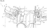
- the figures 2 to 5 make it possible to visualize in more detail certain elements of the opening and closing system 12, placed in the compartment 18.
- the inner shell 16 comprises two cages 19, 20 in which two latches 21, 22 are respectively mounted in slide connections with axes X2 and X3. These two axes X2 and X3 extend radially on the cover 10, as shown in the figure 2 .
- Two return springs 23, 24 are placed in these cages 19, 20 between the rear ends 21a, 22a of the bolts 21, 22 and the rear ends 19a, 20a of said cages 19, 20, which makes it possible to naturally bring back said bolts 21, 22 in a locking position where the heads 25, 25' of the bolts 21, 22 have come out of the cages 19, 20 and emerge towards the front of the inner shell 16 passing through two windows 160, 161 arranged on a contour 162 of said inner shell 16, as shown in particular in the figure 4 .
- the heads 25, 25' of the locks 21, 22 each comprise an upper bevel 25a, 25'a and a lower bevel 25b, 25'b.
- the body 2 of the machine 1 comprises two receiving housings 26, 27 which receive the heads 25, 25' of the bolts 21, 22 when the cover 10 is in the closed position.
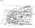
- These receiving housings 26, 27 comprise an upper bevel 26a illustrated on the figures 6 to 9 . Only the upper bevel 26a of the receiving housing 26 is illustrated in the figures 6 to 9 , this upper bevel also existing for the other receiving housing 27.
- the upper bevel 26a on the receiving housings 26, 27 and the upper bevel 25a, 25'a on the heads 25, 25' of the locks 21, 22 will facilitate the retraction of the locks 21, 22 inside the cages 19, 20 in an unlocking position, in which the springs 23, 24 are compressed, when the cover 10 is lifted upwards and moves away from the body 2 of the machine 1, as explained in the following description.
- the upper bevels 26a of the receiving housings 26, 27 do not appear, these upper bevels 26a being arranged on a part 200 of the body 2 not shown in this figure 5 , in order to be able to visualize the positioning of the heads 25, 25' of the bolts 21, 22 in the said receiving housings 26, 27, the said part 200 however appearing on the figures 6 to 9 .
- a support part 28 is mounted in the compartment 18 and secured to the outer 13 and inner 16 shells.
- This support part 28 comprises two lateral end portions 28a, 28b which define two first bearing parts 30a, 31a, which cooperate with two second parts of bearings 30b arranged on an internal face 29 of the external shell 13.
- the second bearing part 30b is illustrated which cooperates with the lateral end portion 28a of the support part 28, the design of the second bearing part cooperating with the other lateral end portion 28b of the support 28 being identical.
- the part of the support 28 is not illustrated, to better discern the other elements of the opening and closing system 12.
- first bearing parts 30a, 31a and second bearing parts 30b cooperate to receive in pivot connection of axis X4 two cylindrical studs 32, 33 arranged on the lateral sides 15a, 15b of the handle 15.
- These studs 32, 33 of the handle 15 extend inside the compartment 18 from two side faces 14a, 14b of the cavity 14 receiving said handle 15 on the outside of the outer shell 13.
- the handle 15 can be gripped from the outside of the cover 10 by placing the fingers of the hand in the cavity 14, then pulled towards the top, which causes the handle 15 to pivot along the axis X4.
- a separating member 34 is placed in the compartment 18 and comprises in its front part two tabs 35, 36 which extend forwards and are curved downwards. These two tabs 35, 36 pass through two respective openings 37, 38 arranged on the inner shell 16 in order to bear against an upper face 39a of a flange 39 arranged on the part 200 of the body 2.
- the separation member 34 comprises in its rear part two pins 40, 41 which extend downwards. These two pins 40, 41 are arranged respectively opposite two tubular cavities 42 arranged on the internal shell 16, inside the compartment 18.
- each tubular cavity 42 and respective pin 40, 41 allow the reception of a spring 43, 44 mounted in compression between the inner shell 16 and the separating member 34.
- the tubular cavities 42 receive the lower portions of the springs 43, 44 and the pins 40, 41 engage in the upper portions of the springs 43, 44.
- the handle 15 comprises a front face 45 whose lower edge 46 bears against two upper front parts 47, 47' of the separating member 34.
- the supports between said upper front parts 47, 47' and said lower edge 46 are offset forwards relative to the pivot axis X4 of the handle 15 and, conversely, are offset rearwards relative to the supports of the tabs 35, 36 on the rim 39 of the part 200 of the body 2.
- the separation member 34 is mounted in equilibrium in the compartment 18 thanks to the springs 43, 44 which maintain in support the upper front parts 47, 47' against the lower edge 46 and the tabs 35, 36 against the rim 39.
- the tabs 35, 36 therefore come into the extended position vis-à-vis the openings 37, 38, as shown in the figure 8 .
- the lifting of the lid 10 vis-à-vis the body 2 causes the upward movement of the locks 21, 22 until the upper bevels 25a, 25'a of the heads 25, 25' come to rest on the upper bevels 26a of the receiving housings 26,27, which forces the movement of the locks 21, 22 backwards along the axes X2 and X3, in the retracted position in the cages 19, 20 (unlocking position), as soon as the force of lifting the cover 10 relative to the body 2 overcomes the restoring force of the springs 23, 24.
- the cover 10 can pass into the open position, the springs 23, 24 then pushing back the bolts 21, 22 in the extended position of the cages 19, 20 (locking position) once the opening has been made. Thanks to the lever arm exerted as mentioned above, the lifting force of the lid 10 is multiplied when the handle 15 is pulled upwards in the direction of the arrow 48, which makes it possible to open the lid 10 without requiring an effort of significant traction on the handle 15 from the user.
- the separating member 34 has then returned to the position of equilibrium in the compartment 18, a position in which said separating member 34 cannot act either on the lid 10 or on the rim 39 of the body 2, which again allows the closing of the lid 10 without any action of the separating member 34 on the lid 10 and on the rim 39 of the body 2 during said closing.
- the lugs 35, 36 therefore come into the retracted position vis-à-vis the openings 37, 38 of the inner shell 16, as shown in the figure 6 .
- the embodiment described previously in support of the figures 1 to 9 is not limiting, variants being possible.
- the receiving housings 26, 27 could be arranged on the cover 10 and, conversely, the cages 19, 20, springs 23, 24 and latches 21, 22 could be arranged on the body 2.
- the opening and closing system 12 then comprising as many receiving housings, cages and return springs.
- the handle 15 and the separating member 34 on the body 2, the actuation of the handle 15 then making it possible to push on the cover 10 to lift it from the body 2 and ensure the release of the locks 21, 22 out of the receiving housings 26, 27 once the lifting force exceeds the return force of the return springs 23, 24.
Landscapes
- Closures For Containers (AREA)
- Devices For Dispensing Beverages (AREA)
Applications Claiming Priority (1)
| Application Number | Priority Date | Filing Date | Title |
|---|---|---|---|
| FR2103453A FR3121436B1 (fr) | 2021-04-02 | 2021-04-02 | Machine de distribution de boisson équipée d’un couvercle de fermeture d’une chambre de réception d’un contenant de boisson tel qu’un fût. |
Publications (3)
| Publication Number | Publication Date |
|---|---|
| EP4067295A1 true EP4067295A1 (de) | 2022-10-05 |
| EP4067295C0 EP4067295C0 (de) | 2024-01-10 |
| EP4067295B1 EP4067295B1 (de) | 2024-01-10 |
Family
ID=75690626
Family Applications (1)
| Application Number | Title | Priority Date | Filing Date |
|---|---|---|---|
| EP22164264.8A Active EP4067295B1 (de) | 2021-04-02 | 2022-03-25 | Getränkeausgabemaschine mit einem deckel zum verschliessen einer kammer zur aufnahme eines getränkebehälters wie z. b. eines fasses |
Country Status (3)
| Country | Link |
|---|---|
| EP (1) | EP4067295B1 (de) |
| CN (1) | CN115196576B (de) |
| FR (1) | FR3121436B1 (de) |
Citations (3)
| Publication number | Priority date | Publication date | Assignee | Title |
|---|---|---|---|---|
| EP0543750A1 (de) * | 1991-11-21 | 1993-05-26 | Seb S.A. | Ver- und Entriegelungsvorrichtung für den Deckel eines Kochgerätes |
| EP0721758A1 (de) * | 1995-01-12 | 1996-07-17 | Moulinex S.A. | Verriegelungs-Entriegelungsvorrichtung für dem Deckel eines Kochgerätes, insbesondere eines Fritiergerätes |
| EP1298088A1 (de) * | 2001-09-28 | 2003-04-02 | Heineken Technical Services B.V. | Getränkeabgabevorrichtung |
Family Cites Families (8)
| Publication number | Priority date | Publication date | Assignee | Title |
|---|---|---|---|---|
| EP1621514B1 (de) * | 1997-09-04 | 2010-04-21 | Heineken Supply Chain B.V. | Getränkespender |
| US7461586B2 (en) * | 2001-12-11 | 2008-12-09 | Hamilton Beach Brands, Inc. | Hot beverage maker with cup-actuated, low-drip dispenser |
| ATE430711T1 (de) * | 2004-09-13 | 2009-05-15 | Micro Matic As | Abgabeleitung für ein abgabesystem |
| WO2006034057A1 (en) * | 2004-09-19 | 2006-03-30 | Southco, Inc. | Rotary pawl latch |
| US7513192B2 (en) * | 2006-03-23 | 2009-04-07 | Keurig, Incorporated | Beverage forming device with opening/closing mechanism for a beverage cartridge receiver |
| ITMO20070020A1 (it) * | 2007-01-25 | 2008-07-26 | Spm Drink Systems Srl | Recipiente per macchine erogatrici di bevande |
| US10221058B2 (en) * | 2015-10-09 | 2019-03-05 | Cornelius, Inc. | Maneuverable service door for beverage dispensing machines |
| PT3650404T (pt) * | 2018-11-12 | 2021-06-14 | Micro Matic As | Cabeça distribuidora e um sistema de distribuição de bebidas |
-
2021
- 2021-04-02 FR FR2103453A patent/FR3121436B1/fr active Active
-
2022
- 2022-03-21 CN CN202210279836.4A patent/CN115196576B/zh active Active
- 2022-03-25 EP EP22164264.8A patent/EP4067295B1/de active Active
Patent Citations (5)
| Publication number | Priority date | Publication date | Assignee | Title |
|---|---|---|---|---|
| EP0543750A1 (de) * | 1991-11-21 | 1993-05-26 | Seb S.A. | Ver- und Entriegelungsvorrichtung für den Deckel eines Kochgerätes |
| EP0721758A1 (de) * | 1995-01-12 | 1996-07-17 | Moulinex S.A. | Verriegelungs-Entriegelungsvorrichtung für dem Deckel eines Kochgerätes, insbesondere eines Fritiergerätes |
| EP1298088A1 (de) * | 2001-09-28 | 2003-04-02 | Heineken Technical Services B.V. | Getränkeabgabevorrichtung |
| US20030071067A1 (en) * | 2001-09-28 | 2003-04-17 | Robert Sluijter | Beverage dispensing device, provided with a dual closure |
| EP1298088A9 (de) | 2001-09-28 | 2004-08-18 | Heineken Technical Services B.V. | Getränkeabgabevorrichtung |
Also Published As
| Publication number | Publication date |
|---|---|
| FR3121436B1 (fr) | 2023-02-24 |
| CN115196576A (zh) | 2022-10-18 |
| FR3121436A1 (fr) | 2022-10-07 |
| EP4067295C0 (de) | 2024-01-10 |
| CN115196576B (zh) | 2026-04-17 |
| EP4067295B1 (de) | 2024-01-10 |
Similar Documents
| Publication | Publication Date | Title |
|---|---|---|
| EP2103236B1 (de) | Vorrichtung zur Extraktion einer Kapsel | |
| EP2020891B1 (de) | Maschine zur zubereitung von espressoartigem kaffee | |
| EP1139832B1 (de) | Brühkammer für einen automat zum zubereiten von heissen getränken | |
| EP3245914A1 (de) | Öffnungs- und verschlusssystem eines schnellkochtopfs | |
| WO2004071259A1 (fr) | Module d’extraction a fermeture lineaire pour la preparation sous pression d´une boisson a partir d’une capsule | |
| EP2083662A1 (de) | Anordnung mit einem gerät und einer einwegkapsel zur zubereitung eines brühgetränks und kapsel für eine derartige anordnung | |
| EP1941821A1 (de) | Verteiler von nebeneinander angeordneten Rollen, der mit einer unteren Schiebeverschlussklappe ausgestattet ist | |
| EP4026463B1 (de) | Abnehmbarer griff mit optimiertem zusammenbauverfahren | |
| FR2960759A1 (fr) | Appareil electromenager de preparation culinaire comportant un recipient de travail ferme par un couvercle amovible | |
| FR3053230A1 (fr) | Dispositif de preparation de boisson par infusion de poudre contenu dans une capsule | |
| FR2796541A1 (fr) | Dispositif de fermeture/ouverture pour un autocuiseur a couvercle rentrant | |
| EP4067295B1 (de) | Getränkeausgabemaschine mit einem deckel zum verschliessen einer kammer zur aufnahme eines getränkebehälters wie z. b. eines fasses | |
| EP2575570B1 (de) | Anordnung für eine maschine zur herstellung von brühgetränken | |
| EP4298961A1 (de) | Wasserkocher mit dampfablassschaltung | |
| WO2005011454A1 (fr) | Appareil electromenager de preparation culinaire comportant un dispositif de verrouillage et un dispositif de securite sans indexage du couvercle | |
| EP2165632A1 (de) | Auswurfvorrichtung eines Haushaltsgeräts, bestehend aus Schüssel und Motorblock eines Rühr- und Mixgeräts | |
| WO2014013204A1 (fr) | Tire-bouchon pour l'ouverture des bouteilles contenant des liquides sous pression | |
| EP4188867B1 (de) | Vorrichtung zur abgabe eines produkts, insbesondere eines in einen flexiblen beutel gefüllten fluids | |
| FR3080109A1 (fr) | Dispositif decapsuleur - recapsuleur | |
| FR2931641A1 (fr) | Contenant definissant interieurement au moins un compartiment de reception d'un article cosmetique. | |
| EP4056075A1 (de) | Präsentationsvorrichtung für lose produkte | |
| FR2935874A1 (fr) | Contenant definissant interieurement au moins un compatiment de reception d'un article cosmetique. | |
| FR2972181A1 (fr) | Dispositif d'emballage et de presentation d'un objet tel qu'une bouteille, carafe ou flacon | |
| FR3004324A1 (fr) | Distributeur de capsules | |
| FR2986786A1 (fr) | Dispositif de stockage et de distribution de pilules ou de produits analogues |
Legal Events
| Date | Code | Title | Description |
|---|---|---|---|
| PUAI | Public reference made under article 153(3) epc to a published international application that has entered the european phase |
Free format text: ORIGINAL CODE: 0009012 |
|
| STAA | Information on the status of an ep patent application or granted ep patent |
Free format text: STATUS: THE APPLICATION HAS BEEN PUBLISHED |
|
| AK | Designated contracting states |
Kind code of ref document: A1 Designated state(s): AL AT BE BG CH CY CZ DE DK EE ES FI FR GB GR HR HU IE IS IT LI LT LU LV MC MK MT NL NO PL PT RO RS SE SI SK SM TR |
|
| STAA | Information on the status of an ep patent application or granted ep patent |
Free format text: STATUS: REQUEST FOR EXAMINATION WAS MADE |
|
| 17P | Request for examination filed |
Effective date: 20230309 |
|
| RBV | Designated contracting states (corrected) |
Designated state(s): AL AT BE BG CH CY CZ DE DK EE ES FI FR GB GR HR HU IE IS IT LI LT LU LV MC MK MT NL NO PL PT RO RS SE SI SK SM TR |
|
| GRAP | Despatch of communication of intention to grant a patent |
Free format text: ORIGINAL CODE: EPIDOSNIGR1 |
|
| STAA | Information on the status of an ep patent application or granted ep patent |
Free format text: STATUS: GRANT OF PATENT IS INTENDED |
|
| INTG | Intention to grant announced |
Effective date: 20230807 |
|
| GRAS | Grant fee paid |
Free format text: ORIGINAL CODE: EPIDOSNIGR3 |
|
| GRAA | (expected) grant |
Free format text: ORIGINAL CODE: 0009210 |
|
| STAA | Information on the status of an ep patent application or granted ep patent |
Free format text: STATUS: THE PATENT HAS BEEN GRANTED |
|
| AK | Designated contracting states |
Kind code of ref document: B1 Designated state(s): AL AT BE BG CH CY CZ DE DK EE ES FI FR GB GR HR HU IE IS IT LI LT LU LV MC MK MT NL NO PL PT RO RS SE SI SK SM TR |
|
| REG | Reference to a national code |
Ref country code: GB Ref legal event code: FG4D Free format text: NOT ENGLISH |
|
| REG | Reference to a national code |
Ref country code: CH Ref legal event code: EP |
|
| REG | Reference to a national code |
Ref country code: DE Ref legal event code: R096 Ref document number: 602022001581 Country of ref document: DE |
|
| REG | Reference to a national code |
Ref country code: IE Ref legal event code: FG4D Free format text: LANGUAGE OF EP DOCUMENT: FRENCH |
|
| U01 | Request for unitary effect filed |
Effective date: 20240129 |
|
| U07 | Unitary effect registered |
Designated state(s): AT BE BG DE DK EE FI FR IT LT LU LV MT NL PT SE SI Effective date: 20240207 |
|
| U20 | Renewal fee for the european patent with unitary effect paid |
Year of fee payment: 3 Effective date: 20240226 |
|
| PG25 | Lapsed in a contracting state [announced via postgrant information from national office to epo] |
Ref country code: IS Free format text: LAPSE BECAUSE OF FAILURE TO SUBMIT A TRANSLATION OF THE DESCRIPTION OR TO PAY THE FEE WITHIN THE PRESCRIBED TIME-LIMIT Effective date: 20240510 |
|
| PG25 | Lapsed in a contracting state [announced via postgrant information from national office to epo] |
Ref country code: GR Free format text: LAPSE BECAUSE OF FAILURE TO SUBMIT A TRANSLATION OF THE DESCRIPTION OR TO PAY THE FEE WITHIN THE PRESCRIBED TIME-LIMIT Effective date: 20240411 |
|
| PG25 | Lapsed in a contracting state [announced via postgrant information from national office to epo] |
Ref country code: RS Free format text: LAPSE BECAUSE OF FAILURE TO SUBMIT A TRANSLATION OF THE DESCRIPTION OR TO PAY THE FEE WITHIN THE PRESCRIBED TIME-LIMIT Effective date: 20240410 Ref country code: HR Free format text: LAPSE BECAUSE OF FAILURE TO SUBMIT A TRANSLATION OF THE DESCRIPTION OR TO PAY THE FEE WITHIN THE PRESCRIBED TIME-LIMIT Effective date: 20240110 |
|
| PG25 | Lapsed in a contracting state [announced via postgrant information from national office to epo] |
Ref country code: ES Free format text: LAPSE BECAUSE OF FAILURE TO SUBMIT A TRANSLATION OF THE DESCRIPTION OR TO PAY THE FEE WITHIN THE PRESCRIBED TIME-LIMIT Effective date: 20240110 |
|
| PG25 | Lapsed in a contracting state [announced via postgrant information from national office to epo] |
Ref country code: RS Free format text: LAPSE BECAUSE OF FAILURE TO SUBMIT A TRANSLATION OF THE DESCRIPTION OR TO PAY THE FEE WITHIN THE PRESCRIBED TIME-LIMIT Effective date: 20240410 Ref country code: NO Free format text: LAPSE BECAUSE OF FAILURE TO SUBMIT A TRANSLATION OF THE DESCRIPTION OR TO PAY THE FEE WITHIN THE PRESCRIBED TIME-LIMIT Effective date: 20240410 Ref country code: IS Free format text: LAPSE BECAUSE OF FAILURE TO SUBMIT A TRANSLATION OF THE DESCRIPTION OR TO PAY THE FEE WITHIN THE PRESCRIBED TIME-LIMIT Effective date: 20240510 Ref country code: HR Free format text: LAPSE BECAUSE OF FAILURE TO SUBMIT A TRANSLATION OF THE DESCRIPTION OR TO PAY THE FEE WITHIN THE PRESCRIBED TIME-LIMIT Effective date: 20240110 Ref country code: GR Free format text: LAPSE BECAUSE OF FAILURE TO SUBMIT A TRANSLATION OF THE DESCRIPTION OR TO PAY THE FEE WITHIN THE PRESCRIBED TIME-LIMIT Effective date: 20240411 Ref country code: ES Free format text: LAPSE BECAUSE OF FAILURE TO SUBMIT A TRANSLATION OF THE DESCRIPTION OR TO PAY THE FEE WITHIN THE PRESCRIBED TIME-LIMIT Effective date: 20240110 |
|
| PG25 | Lapsed in a contracting state [announced via postgrant information from national office to epo] |
Ref country code: PL Free format text: LAPSE BECAUSE OF FAILURE TO SUBMIT A TRANSLATION OF THE DESCRIPTION OR TO PAY THE FEE WITHIN THE PRESCRIBED TIME-LIMIT Effective date: 20240110 |
|
| PG25 | Lapsed in a contracting state [announced via postgrant information from national office to epo] |
Ref country code: PL Free format text: LAPSE BECAUSE OF FAILURE TO SUBMIT A TRANSLATION OF THE DESCRIPTION OR TO PAY THE FEE WITHIN THE PRESCRIBED TIME-LIMIT Effective date: 20240110 |
|
| REG | Reference to a national code |
Ref country code: DE Ref legal event code: R097 Ref document number: 602022001581 Country of ref document: DE |
|
| PG25 | Lapsed in a contracting state [announced via postgrant information from national office to epo] |
Ref country code: SM Free format text: LAPSE BECAUSE OF FAILURE TO SUBMIT A TRANSLATION OF THE DESCRIPTION OR TO PAY THE FEE WITHIN THE PRESCRIBED TIME-LIMIT Effective date: 20240110 |
|
| PG25 | Lapsed in a contracting state [announced via postgrant information from national office to epo] |
Ref country code: CZ Free format text: LAPSE BECAUSE OF FAILURE TO SUBMIT A TRANSLATION OF THE DESCRIPTION OR TO PAY THE FEE WITHIN THE PRESCRIBED TIME-LIMIT Effective date: 20240110 |
|
| PG25 | Lapsed in a contracting state [announced via postgrant information from national office to epo] |
Ref country code: SK Free format text: LAPSE BECAUSE OF FAILURE TO SUBMIT A TRANSLATION OF THE DESCRIPTION OR TO PAY THE FEE WITHIN THE PRESCRIBED TIME-LIMIT Effective date: 20240110 |
|
| PG25 | Lapsed in a contracting state [announced via postgrant information from national office to epo] |
Ref country code: SM Free format text: LAPSE BECAUSE OF FAILURE TO SUBMIT A TRANSLATION OF THE DESCRIPTION OR TO PAY THE FEE WITHIN THE PRESCRIBED TIME-LIMIT Effective date: 20240110 Ref country code: SK Free format text: LAPSE BECAUSE OF FAILURE TO SUBMIT A TRANSLATION OF THE DESCRIPTION OR TO PAY THE FEE WITHIN THE PRESCRIBED TIME-LIMIT Effective date: 20240110 Ref country code: RO Free format text: LAPSE BECAUSE OF FAILURE TO SUBMIT A TRANSLATION OF THE DESCRIPTION OR TO PAY THE FEE WITHIN THE PRESCRIBED TIME-LIMIT Effective date: 20240110 Ref country code: CZ Free format text: LAPSE BECAUSE OF FAILURE TO SUBMIT A TRANSLATION OF THE DESCRIPTION OR TO PAY THE FEE WITHIN THE PRESCRIBED TIME-LIMIT Effective date: 20240110 |
|
| PLBE | No opposition filed within time limit |
Free format text: ORIGINAL CODE: 0009261 |
|
| STAA | Information on the status of an ep patent application or granted ep patent |
Free format text: STATUS: NO OPPOSITION FILED WITHIN TIME LIMIT |
|
| PG25 | Lapsed in a contracting state [announced via postgrant information from national office to epo] |
Ref country code: MC Free format text: LAPSE BECAUSE OF FAILURE TO SUBMIT A TRANSLATION OF THE DESCRIPTION OR TO PAY THE FEE WITHIN THE PRESCRIBED TIME-LIMIT Effective date: 20240110 |
|
| PG25 | Lapsed in a contracting state [announced via postgrant information from national office to epo] |
Ref country code: MC Free format text: LAPSE BECAUSE OF FAILURE TO SUBMIT A TRANSLATION OF THE DESCRIPTION OR TO PAY THE FEE WITHIN THE PRESCRIBED TIME-LIMIT Effective date: 20240110 |
|
| 26N | No opposition filed |
Effective date: 20241011 |
|
| PG25 | Lapsed in a contracting state [announced via postgrant information from national office to epo] |
Ref country code: IE Free format text: LAPSE BECAUSE OF NON-PAYMENT OF DUE FEES Effective date: 20240325 |
|
| PG25 | Lapsed in a contracting state [announced via postgrant information from national office to epo] |
Ref country code: IE Free format text: LAPSE BECAUSE OF NON-PAYMENT OF DUE FEES Effective date: 20240325 |
|
| U20 | Renewal fee for the european patent with unitary effect paid |
Year of fee payment: 4 Effective date: 20250225 |
|
| PG25 | Lapsed in a contracting state [announced via postgrant information from national office to epo] |
Ref country code: CY Free format text: LAPSE BECAUSE OF FAILURE TO SUBMIT A TRANSLATION OF THE DESCRIPTION OR TO PAY THE FEE WITHIN THE PRESCRIBED TIME-LIMIT; INVALID AB INITIO Effective date: 20220325 |
|
| REG | Reference to a national code |
Ref country code: CH Ref legal event code: H13 Free format text: ST27 STATUS EVENT CODE: U-0-0-H10-H13 (AS PROVIDED BY THE NATIONAL OFFICE) Effective date: 20251023 |
|
| PG25 | Lapsed in a contracting state [announced via postgrant information from national office to epo] |
Ref country code: TR Free format text: LAPSE BECAUSE OF FAILURE TO SUBMIT A TRANSLATION OF THE DESCRIPTION OR TO PAY THE FEE WITHIN THE PRESCRIBED TIME-LIMIT Effective date: 20240110 |
|
| PG25 | Lapsed in a contracting state [announced via postgrant information from national office to epo] |
Ref country code: CH Free format text: LAPSE BECAUSE OF NON-PAYMENT OF DUE FEES Effective date: 20250331 |
|
| U20 | Renewal fee for the european patent with unitary effect paid |
Year of fee payment: 5 Effective date: 20260226 |