EP4067548B1 - Installation de consolidation des couches comprenant des fibres en une bande de non-tissée - Google Patents
Installation de consolidation des couches comprenant des fibres en une bande de non-tissée Download PDFInfo
- Publication number
- EP4067548B1 EP4067548B1 EP22163578.2A EP22163578A EP4067548B1 EP 4067548 B1 EP4067548 B1 EP 4067548B1 EP 22163578 A EP22163578 A EP 22163578A EP 4067548 B1 EP4067548 B1 EP 4067548B1
- Authority
- EP
- European Patent Office
- Prior art keywords
- strand
- belt
- fibers
- transfer belt
- layer
- Prior art date
- Legal status (The legal status is an assumption and is not a legal conclusion. Google has not performed a legal analysis and makes no representation as to the accuracy of the status listed.)
- Active
Links
Images

Classifications
-
- D—TEXTILES; PAPER
- D04—BRAIDING; LACE-MAKING; KNITTING; TRIMMINGS; NON-WOVEN FABRICS
- D04H—MAKING TEXTILE FABRICS, e.g. FROM FIBRES OR FILAMENTARY MATERIAL; FABRICS MADE BY SUCH PROCESSES OR APPARATUS, e.g. FELTS, NON-WOVEN FABRICS; COTTON-WOOL; WADDING ; NON-WOVEN FABRICS FROM STAPLE FIBRES, FILAMENTS OR YARNS, BONDED WITH AT LEAST ONE WEB-LIKE MATERIAL DURING THEIR CONSOLIDATION
- D04H1/00—Non-woven fabrics formed wholly or mainly of staple fibres or like relatively short fibres
- D04H1/70—Non-woven fabrics formed wholly or mainly of staple fibres or like relatively short fibres characterised by the method of forming fleeces or layers, e.g. reorientation of fibres
-
- D—TEXTILES; PAPER
- D04—BRAIDING; LACE-MAKING; KNITTING; TRIMMINGS; NON-WOVEN FABRICS
- D04H—MAKING TEXTILE FABRICS, e.g. FROM FIBRES OR FILAMENTARY MATERIAL; FABRICS MADE BY SUCH PROCESSES OR APPARATUS, e.g. FELTS, NON-WOVEN FABRICS; COTTON-WOOL; WADDING ; NON-WOVEN FABRICS FROM STAPLE FIBRES, FILAMENTS OR YARNS, BONDED WITH AT LEAST ONE WEB-LIKE MATERIAL DURING THEIR CONSOLIDATION
- D04H1/00—Non-woven fabrics formed wholly or mainly of staple fibres or like relatively short fibres
- D04H1/40—Non-woven fabrics formed wholly or mainly of staple fibres or like relatively short fibres from fleeces or layers composed of fibres without existing or potential cohesive properties
- D04H1/44—Non-woven fabrics formed wholly or mainly of staple fibres or like relatively short fibres from fleeces or layers composed of fibres without existing or potential cohesive properties the fleeces or layers being consolidated by mechanical means, e.g. by rolling
- D04H1/46—Non-woven fabrics formed wholly or mainly of staple fibres or like relatively short fibres from fleeces or layers composed of fibres without existing or potential cohesive properties the fleeces or layers being consolidated by mechanical means, e.g. by rolling by needling or like operations to cause entanglement of fibres
- D04H1/48—Non-woven fabrics formed wholly or mainly of staple fibres or like relatively short fibres from fleeces or layers composed of fibres without existing or potential cohesive properties the fleeces or layers being consolidated by mechanical means, e.g. by rolling by needling or like operations to cause entanglement of fibres in combination with at least one other method of consolidation
- D04H1/49—Non-woven fabrics formed wholly or mainly of staple fibres or like relatively short fibres from fleeces or layers composed of fibres without existing or potential cohesive properties the fleeces or layers being consolidated by mechanical means, e.g. by rolling by needling or like operations to cause entanglement of fibres in combination with at least one other method of consolidation entanglement by fluid jet in combination with another consolidation means
-
- D—TEXTILES; PAPER
- D04—BRAIDING; LACE-MAKING; KNITTING; TRIMMINGS; NON-WOVEN FABRICS
- D04H—MAKING TEXTILE FABRICS, e.g. FROM FIBRES OR FILAMENTARY MATERIAL; FABRICS MADE BY SUCH PROCESSES OR APPARATUS, e.g. FELTS, NON-WOVEN FABRICS; COTTON-WOOL; WADDING ; NON-WOVEN FABRICS FROM STAPLE FIBRES, FILAMENTS OR YARNS, BONDED WITH AT LEAST ONE WEB-LIKE MATERIAL DURING THEIR CONSOLIDATION
- D04H1/00—Non-woven fabrics formed wholly or mainly of staple fibres or like relatively short fibres
-
- B—PERFORMING OPERATIONS; TRANSPORTING
- B29—WORKING OF PLASTICS; WORKING OF SUBSTANCES IN A PLASTIC STATE IN GENERAL
- B29C—SHAPING OR JOINING OF PLASTICS; SHAPING OF MATERIAL IN A PLASTIC STATE, NOT OTHERWISE PROVIDED FOR; AFTER-TREATMENT OF THE SHAPED PRODUCTS, e.g. REPAIRING
- B29C53/00—Shaping by bending, folding, twisting, straightening or flattening; Apparatus therefor
- B29C53/56—Winding and joining, e.g. winding spirally
- B29C53/58—Winding and joining, e.g. winding spirally helically
- B29C53/60—Winding and joining, e.g. winding spirally helically using internal forming surfaces, e.g. mandrels
-
- D—TEXTILES; PAPER
- D04—BRAIDING; LACE-MAKING; KNITTING; TRIMMINGS; NON-WOVEN FABRICS
- D04H—MAKING TEXTILE FABRICS, e.g. FROM FIBRES OR FILAMENTARY MATERIAL; FABRICS MADE BY SUCH PROCESSES OR APPARATUS, e.g. FELTS, NON-WOVEN FABRICS; COTTON-WOOL; WADDING ; NON-WOVEN FABRICS FROM STAPLE FIBRES, FILAMENTS OR YARNS, BONDED WITH AT LEAST ONE WEB-LIKE MATERIAL DURING THEIR CONSOLIDATION
- D04H1/00—Non-woven fabrics formed wholly or mainly of staple fibres or like relatively short fibres
- D04H1/40—Non-woven fabrics formed wholly or mainly of staple fibres or like relatively short fibres from fleeces or layers composed of fibres without existing or potential cohesive properties
- D04H1/44—Non-woven fabrics formed wholly or mainly of staple fibres or like relatively short fibres from fleeces or layers composed of fibres without existing or potential cohesive properties the fleeces or layers being consolidated by mechanical means, e.g. by rolling
- D04H1/46—Non-woven fabrics formed wholly or mainly of staple fibres or like relatively short fibres from fleeces or layers composed of fibres without existing or potential cohesive properties the fleeces or layers being consolidated by mechanical means, e.g. by rolling by needling or like operations to cause entanglement of fibres
- D04H1/498—Non-woven fabrics formed wholly or mainly of staple fibres or like relatively short fibres from fleeces or layers composed of fibres without existing or potential cohesive properties the fleeces or layers being consolidated by mechanical means, e.g. by rolling by needling or like operations to cause entanglement of fibres entanglement of layered webs
-
- D—TEXTILES; PAPER
- D04—BRAIDING; LACE-MAKING; KNITTING; TRIMMINGS; NON-WOVEN FABRICS
- D04H—MAKING TEXTILE FABRICS, e.g. FROM FIBRES OR FILAMENTARY MATERIAL; FABRICS MADE BY SUCH PROCESSES OR APPARATUS, e.g. FELTS, NON-WOVEN FABRICS; COTTON-WOOL; WADDING ; NON-WOVEN FABRICS FROM STAPLE FIBRES, FILAMENTS OR YARNS, BONDED WITH AT LEAST ONE WEB-LIKE MATERIAL DURING THEIR CONSOLIDATION
- D04H1/00—Non-woven fabrics formed wholly or mainly of staple fibres or like relatively short fibres
- D04H1/70—Non-woven fabrics formed wholly or mainly of staple fibres or like relatively short fibres characterised by the method of forming fleeces or layers, e.g. reorientation of fibres
- D04H1/72—Non-woven fabrics formed wholly or mainly of staple fibres or like relatively short fibres characterised by the method of forming fleeces or layers, e.g. reorientation of fibres the fibres being randomly arranged
- D04H1/732—Non-woven fabrics formed wholly or mainly of staple fibres or like relatively short fibres characterised by the method of forming fleeces or layers, e.g. reorientation of fibres the fibres being randomly arranged by fluid current, e.g. air-lay
-
- D—TEXTILES; PAPER
- D04—BRAIDING; LACE-MAKING; KNITTING; TRIMMINGS; NON-WOVEN FABRICS
- D04H—MAKING TEXTILE FABRICS, e.g. FROM FIBRES OR FILAMENTARY MATERIAL; FABRICS MADE BY SUCH PROCESSES OR APPARATUS, e.g. FELTS, NON-WOVEN FABRICS; COTTON-WOOL; WADDING ; NON-WOVEN FABRICS FROM STAPLE FIBRES, FILAMENTS OR YARNS, BONDED WITH AT LEAST ONE WEB-LIKE MATERIAL DURING THEIR CONSOLIDATION
- D04H1/00—Non-woven fabrics formed wholly or mainly of staple fibres or like relatively short fibres
- D04H1/70—Non-woven fabrics formed wholly or mainly of staple fibres or like relatively short fibres characterised by the method of forming fleeces or layers, e.g. reorientation of fibres
- D04H1/74—Non-woven fabrics formed wholly or mainly of staple fibres or like relatively short fibres characterised by the method of forming fleeces or layers, e.g. reorientation of fibres the fibres being orientated, e.g. in parallel (anisotropic fleeces)
-
- D—TEXTILES; PAPER
- D04—BRAIDING; LACE-MAKING; KNITTING; TRIMMINGS; NON-WOVEN FABRICS
- D04H—MAKING TEXTILE FABRICS, e.g. FROM FIBRES OR FILAMENTARY MATERIAL; FABRICS MADE BY SUCH PROCESSES OR APPARATUS, e.g. FELTS, NON-WOVEN FABRICS; COTTON-WOOL; WADDING ; NON-WOVEN FABRICS FROM STAPLE FIBRES, FILAMENTS OR YARNS, BONDED WITH AT LEAST ONE WEB-LIKE MATERIAL DURING THEIR CONSOLIDATION
- D04H5/00—Non woven fabrics formed of mixtures of relatively short fibres and yarns or like filamentary material of substantial length
- D04H5/02—Non woven fabrics formed of mixtures of relatively short fibres and yarns or like filamentary material of substantial length strengthened or consolidated by mechanical methods, e.g. needling
-
- D—TEXTILES; PAPER
- D04—BRAIDING; LACE-MAKING; KNITTING; TRIMMINGS; NON-WOVEN FABRICS
- D04H—MAKING TEXTILE FABRICS, e.g. FROM FIBRES OR FILAMENTARY MATERIAL; FABRICS MADE BY SUCH PROCESSES OR APPARATUS, e.g. FELTS, NON-WOVEN FABRICS; COTTON-WOOL; WADDING ; NON-WOVEN FABRICS FROM STAPLE FIBRES, FILAMENTS OR YARNS, BONDED WITH AT LEAST ONE WEB-LIKE MATERIAL DURING THEIR CONSOLIDATION
- D04H5/00—Non woven fabrics formed of mixtures of relatively short fibres and yarns or like filamentary material of substantial length
- D04H5/02—Non woven fabrics formed of mixtures of relatively short fibres and yarns or like filamentary material of substantial length strengthened or consolidated by mechanical methods, e.g. needling
- D04H5/03—Non woven fabrics formed of mixtures of relatively short fibres and yarns or like filamentary material of substantial length strengthened or consolidated by mechanical methods, e.g. needling by fluid jet
-
- D—TEXTILES; PAPER
- D04—BRAIDING; LACE-MAKING; KNITTING; TRIMMINGS; NON-WOVEN FABRICS
- D04H—MAKING TEXTILE FABRICS, e.g. FROM FIBRES OR FILAMENTARY MATERIAL; FABRICS MADE BY SUCH PROCESSES OR APPARATUS, e.g. FELTS, NON-WOVEN FABRICS; COTTON-WOOL; WADDING ; NON-WOVEN FABRICS FROM STAPLE FIBRES, FILAMENTS OR YARNS, BONDED WITH AT LEAST ONE WEB-LIKE MATERIAL DURING THEIR CONSOLIDATION
- D04H5/00—Non woven fabrics formed of mixtures of relatively short fibres and yarns or like filamentary material of substantial length
- D04H5/08—Non woven fabrics formed of mixtures of relatively short fibres and yarns or like filamentary material of substantial length characterised by the method of forming fleeces or layers, e.g. reorientation of fibres or yarns
-
- D—TEXTILES; PAPER
- D06—TREATMENT OF TEXTILES OR THE LIKE; LAUNDERING; FLEXIBLE MATERIALS NOT OTHERWISE PROVIDED FOR
- D06C—FINISHING, DRESSING, TENTERING OR STRETCHING TEXTILE FABRICS
- D06C21/00—Shrinking by compressing
- D06C21/005—Compacting belts
Definitions
- the invention relates to a system for bonding a layer comprising short fibers with a layer comprising long fibers to form a fleece web, with a first circulating belt on which the layer comprising long fibers can be deposited and displaced in a production direction, with a circulating depositing belt on which the short fibers are placed with a Headbox can be deposited to form the layer and which has a delivery strand, with a revolving transfer belt with a receiving strand, by means of which the layer comprising short fibers can be transferred to the layer comprising long fibers at a transition point, and with a with the delivery strand or preferably with the receiving strand in Actively connected device with which delivery strand and receiving strand between a takeover position, in which at least a significant proportion of the fibers are transferred from the delivery strand to the receiving strand and continued by the takeover belt, and a rest position, in which delivery strand and recording strand are spaced from each other and at least a significant portion of the fibers are not transferred to the receiving
- a system for producing a nonwoven web with a device with a continuously circulating deposit belt is from EP 3 283 679 B1 known.
- the fibers become continuous, for example in the form of an aqueous emulsion placed on the storage belt.
- the device is arranged in such a way that the layer of fibers is deposited from the deposit belt at a transfer point on top of a second fiber layer advancing in the direction of production and fed to production steps for forming a fleece web, such as compaction and consolidation.
- Providing the layer of fibers with such a device can be problematic if it has to be interrupted, for example because a change is to be made to another layer to which the layer of fibers is to be released from the transfer point. Because with the regularly used, state-of-the-art headboxes, a short-term interruption of the depositing process is not possible due to their construction. If the circulation of the deposit belt were stopped at the transition point to interrupt the delivery of the fiber layer, this would result in an undesirably large quantity of fibers being deposited on the deposit belt in the area of the headbox, which would lead to problems when restarting the system and at least to the formation of defective areas of the nonwoven web to be produced would result.
- a circulating transfer belt with a receiving strand by means of which the layer comprising short fibers can be transferred to the layer comprising long fibers at a transition point, and with a device that is operatively connected to the delivery strand or preferably to the receiving strand, with which delivery strand and receiving strand between a transfer position, in which at least a substantial proportion of the fibers are transferred from the dispensing strand to the receiving strand and carried on by the receiving belt, and a rest position, in which the dispensing strand and receiving strand are spaced apart and at least a substantial A proportion of the fibers is not transferred to the receiving strand and is guided further by the deposit belt, can be displaced, in order to be able to effect or interrupt the transfer of the layer comprising short fibers to the layer comprising long fibers without the headbox having to be interrupted for this purpose.
- Plants having a pre-consolidation unit for consolidating a layer comprising short fibers with a layer comprising long fibers to form a nonwoven web are from U.S. 2002/157766 A1 and WO 2004/063451 A1 known.
- the invention is based on the object of further developing a system with the features mentioned at the outset in such a way that it is particularly well suited for the production of a nonwoven web, in which a layer comprising light short fibers, e.g. with a weight per unit area between 5 and 50 grams per square meter, e.g. a light and wet wood fiber layer is applied to and consolidated with a layer comprising long fibers, which can have, for example, a basis weight of between 15 and 50 grams per square meter.
- This production regularly causes difficulties, since carded layers comprising long fibers often have elastic properties and show recovery effects after compaction, which can result in deformations, defects and even cracks in the wood fiber layer.
- the nonwoven web produced can, for example, have a basis weight of between 20 and 150, preferably between 40 and 70 grams per square meter.
- the system according to the invention comprises a pre-consolidation unit which has two compacting devices which are spaced apart from one another in the production direction and which act on the transfer belt in one area and form a lower run of the transfer belt between them.
- the pre-consolidation unit has two compacting devices that are spaced apart from one another in the direction of production. With these, a distance between the transfer belt and the first belt, which preferably runs parallel thereto, can be reduced in one area to a value that is smaller than the sum of the thicknesses of the two layers, whereby the two layers are separated due to a compressive force acting on them over an area in the area are compactable.
- the two bands can also contact each other in this area, in other words the distance assume the value zero if no layer passes the preconsolidation unit.
- the belts When passing through one or more layers, the belts can again assume a distance in this area due to the flexibility of at least one of the belts without a displacement of the pre-consolidation unit being absolutely necessary for this purpose.
- the two compacting devices can either both act on one and the same of the first and second band. Or one of the two compactors acts on one band and the other of the two compactors acts on the other band.
- the pre-consolidation unit also comprises a consolidation device arranged between the compaction devices, in particular a water-jet compaction device, by means of which the two layers can be consolidated by swirling the fibers together.
- the compacting device is preferably designed in such a way that the turbulence of the fibers is not achieved over the entire area in which the compaction also takes place, but only in a partial area, in particular linearly by means of a nozzle bar extending transversely to the production direction.
- the compacting device and the solidification device are also integrated into the system in such a way that they are always together in the operating state or in the idle state.
- the devices are preferably always in the operating state when the layer comprising short fibers is transferred by the deposit belt.
- a first preferred embodiment of a plant according to the invention comprises a pre-consolidation unit, in which the compacting devices each comprise a pressure roller.
- the production costs of a system according to the invention can be reduced without restricting its functionality if—as in a second embodiment—the compacting devices of the preconsolidation unit each include a pressure bar.
- the compacting devices of the pre-consolidation unit can be arranged in such a way that in the operating state they bear against the first belt and preferably move it parallel to the second belt in the area in which the pre-consolidation unit acts.
- the guidance of the second belt is preferably selected in such a way that the distance between the line extending transversely to the direction of production, along which the second belt first touches the outer circumference of the pressure roller, to the upper side of the first band corresponds at least to the thickness of the fiber layers. Typically this distance is 15 mm, 20 mm or more. Due to this configuration, an undesirable compacting of the layers before the transfer point is avoided.
- lower rollers around which the second belt rotates are arranged. Due to this measure, an improvement in the guidance of the second band is achieved, which can improve the pre-consolidation process that can be achieved with the system according to the invention.
- An embodiment is particularly preferred in which the lower rollers are arranged in such a way that the transfer belt to the first belt between the lower rollers and the compacting devices adjacent to them have an inlet angle ⁇ between 1° and 10° and an outlet angle ⁇ ′ of greater than 1°. It has been shown that with an approach angle in this size range a particularly good result can be achieved with the pre-consolidation unit, but the size of the outlet angle is only of minor importance for the result.
- the first compacting device acts from above against the lower run of the transfer belt and the second compacting device, seen in the production direction, acts from below against the upper run of the first circulating belt.
- the first circulating belt experiences a change in direction when passing the second compacting device. It is preferably at least 1°. Surprisingly, it has been shown that this reduces the undesired tendency for the pre-consolidated layers to adhere to the transfer belt
- the first compacting device comprises a first lower pressure roller.
- the second compacting device comprises a suction chamber. The tendency of the pre-consolidated layers to stick to the transfer belt is then again substantially reduced.
- the suction chamber then preferably comprises at least one contact surface for the first circulating belt, and furthermore preferably a suction opening.
- the second compacting device comprises a pressure roller, which can be designed in an identical manner to the first lower pressure roller.
- a suction chamber is preferably provided in the production direction—preferably directly behind the pressure roller.
- the pressure roller is designed as a suction roller, by means of which an air flow can be generated through the first circulating belt.
- the hydroentanglement device is preferably designed as a jet bar which is connected to a pressure source, by means of which water can be supplied under a pressure that can be up to 100 bar, but is usually significantly lower, for example a maximum of 30 bar or lower, depending on the reasons requirements influenced by properties of the short and long fibers for the pre-consolidation.
- the jet bar preferably emits jets of water with diameters typically between 80 and 180 microns.
- the nozzle bar is preferably arranged within the transfer belt and—particularly preferably—is at the same distance from the compacting units as viewed in the direction of production.
- the device with which the delivery strand and receiving strand is arranged between the transfer position and the rest position within the transfer belt the space requirement of the device according to the invention can be reduced.
- the space surrounded by the deposit belt is then available for further machine components, such as suction devices for sucking off process water.
- the device comprises a first guide means which abuts or can be brought into contact with the transfer belt in the region of the receiving strand and can be displaced with a movement component perpendicular to the receiving strand.
- the guide means In order to bring the receiving run into the transfer position, it is then necessary to move the guide means in the direction of the receiving run. In the transfer position, it is therefore inevitably on the transfer belt.
- the guide means In order to move the take-up strand into the rest position, the guide means must then be moved in the opposite direction, it being possible for it to lie against the transfer belt in the rest position, but this is not necessary.
- the transfer belt is preferably designed to be at least gas-permeable.
- At least gas-permeable is to be understood as meaning that an additionally water-permeable Formation of the take-over band may be desirable, for example if the take-over band must be penetrable by water jets for the purpose of detaching and/or strengthening the layer of fibers.
- the gas permeability of the take-over belt is particularly necessary when the device—as also preferred—comprises a suction device that can be activated as desired and sucks in the area of the take-up strand from the take-over belt. Due to this measure, the process of transferring the layer of fibers can be supported when the delivery and receiving strands are in the transfer position, since the layer of fibers is sucked in by the transfer belt due to the air flow caused by the suction device.
- the device comprises second guide means which are in contact with or can be brought into contact with the receiving strand in the region of the receiving strand, can be displaced with a movement component perpendicular to the receiving strand and are spaced apart from the first guiding means in the direction of rotation of the receiving strand.
- the suction device is preferably arranged between the first and the second guide means in the direction of rotation of the transfer belt.
- the device is particularly suitable for displacing the receiving strand relative to the delivery strand when it comprises a support structure which is arranged so that it can be moved and/or pivoted parallel to and in relation to the receiving strand by means of a motor.
- a fiber catching device is provided, almost all of the fibers discharged from the headbox reach the fiber catching device when the delivery and receiving strands are in the rest position, in which no transfer of fibers or the layer formed by them to the transfer belt.
- the fiber collecting device is preferably designed in such a way that the collected fibers can be returned to the manufacturing process.
- a particular advantage of providing the fiber catching device is that the system according to the invention has a device for reducing the width of the layer comprising the short fibers by cutting off one or both edge areas of the layer - particularly in the area of the device with which the delivery strand and receiving strand between the transfer - and the rest position can be displaced - can include, and the severed edge regions or the short fibers forming them are collected by the collecting device.
- the collecting device is preferably arranged below the deflection roller.
- the deflection angle is preferably more than 90°.
- the system according to the invention comprises, as is preferred, a carding unit for providing the layer comprising the long fibers, this can be provided inline. If layers of different widths comprising long fibers can be provided by means of the carding unit, as is preferred, then the device for reducing the width of the layer comprising the short fibers is used to adjust the width thereof so that it is at most as wide as the layer comprising long fibers. In this way, short fibers are prevented from adhering to the first circulating belt.
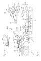
- the plant shown for producing a fleece web 23, which can have a basis weight between 20 and 150 grams per square centimeter, in particular between 40 and 70 grams per square centimeter, comprises a first embodiment of a device (device 100) for providing a layer 13 of fibers 12, in particular short fibers with an average length of between 1 mm and 10 mm and, for example, a basis weight of between 5 and 50 grams per square meter, the structure and function of which is described in detail below.
- the system also includes a carding unit 1, with which a layer 5 of long fibers, in particular a length between 10 mm and 150 mm and, for example, a basis weight between 15 and 50 grams per square centimeter can be produced.
- the carding unit 1 comprises a circulating deposit belt 2 with an upper run 3 on which the long fibers 12 can be deposited to form the layer 13 .
- the system also includes a suction roller 6, with which the layer 5 can be transferred to an upper strand 7 of a first belt 8 circulating around rollers 9 in a clockwise direction.
- the upper run 7 moves in the direction of the arrow drawn in the drawing, which thus symbolizes the production direction P.
- the first circulating belt 8 is designed to be permeable to liquids and gases, for example as a screen belt.
- the device 100 for providing the layer 13 of fibers 12 comprises a depositing belt 14 which runs around rollers 15 in a clockwise direction.
- the depositing belt 14 is in turn designed to be permeable to liquids and gases, for example as a screen belt. Due to the arrangement of the rollers 15, it forms a region 16 that rises as seen in the direction of rotation, in which the fibers 12 are deposited from a headbox 17—for example as an aqueous emulsion—to form the layer 13.
- a headbox 17 for example as an aqueous emulsion
- the delivery belt 14 also includes a region 18 which slopes down obliquely in the direction of rotation and which forms a delivery run 34 .
- the deposit belt 14 is guided over a subsequent roller 15 in a horizontal area 19 which forms a return run 35 .
- a fiber-collecting device 36 is arranged below the roller 15, on which the discharge strand 34 merges into the return strand 35.
- the device 100 also includes a take-over belt 38 which runs counterclockwise around upper rollers 37 and lower rollers 21 and has a receiving strand 39 .
- a device 40 is provided within the space delimited by the transfer belt 38, with which the receiving strand 39 is moved between a transfer position in which a part of the receiving strand 39 is at least almost in contact with the delivery strand 34 of the delivery belt 14 and at least a substantial proportion of the fibers 12 of the layer 13 is transferred from the delivery run 34 to the receiving run 39, and a rest position in which the receiving run 39 is spaced from the delivery run 34 and at least a substantial proportion of the fibers are not transferred to the receiving run. In 1 the resting position is illustrated in section I.
- the device 40 comprises a support structure 41 on which two guide means 42 are arranged which are spaced apart from one another in relation to the direction of rotation of the transfer belt 38 . They each include a roller 43 which bears against the receiving run 39 of the transfer belt 38 from the inside. Seen in the direction of rotation of the transfer belt 38 between the guide means 42 there is a selectively activatable suction device 44 by means of which air can be sucked through the transfer belt 38 and thus the fibers 12 or the layer 13 onto the transfer belt 38 .
- Support structure 41 is linked to a machine frame (not shown in the drawing) via linkage units 45, at least one of which is variable in length, so that device 40 moves between a position in which transfer belt 38 is in the transfer position and a position in which the transfer belt is in the rest position, can be displaced.
- the fibers 12 forming the layer 13 are not transferred to the take-over belt 38 in the rest position, but instead pass from the delivery strand 34 of the delivery belt 14 to the fiber-collecting device 36.
- the fibers 12 reach the transfer belt 38 by coming into contact with the receiving strand 39, if necessary supported by the action of the suction device 44. From this, the fibers 12 or the layer 13 reach a lower strand 20 of the transfer belt 38, which is formed between the lower rollers 21.
- the lower rollers 21, 21' form compacting devices 10, 10' and are part of a pre-consolidation unit 22.
- they are in a position relative to the upper run of the first circulating belt 8 in which the distance between the lower run 20 of the second circulating belt 14 and the upper run 7 of the first circulating belt 8 is smaller than the sum of the thicknesses of the layers 5 and 13.
- the two belts can also contact each other in this area, in other words the distance can have the value zero, when no ply passes the preconsolidation unit 22.
- the belts can again assume a distance due to the flexibility of the first circulating belt 8, without a displacement of the pre-consolidation unit being absolutely necessary for this.
- At least the first roller 21 in the direction of production has a diameter D. It is greater than or equal to one twentieth of the length of the printing roller across the direction of production.
- the guidance of the second band is chosen such that the line extending transversely to the production direction, along which the second band first touches the outer circumference of the roll 21, has a distance A.
- the layer 13 is transferred to the layer 5 at a transfer point Ü, which is in the direction of production P is seen in front of the lower roller 21 shown on the left in the drawing. Since the distance between the upper run 7 and the lower run 20 is smaller than the sum of the thicknesses of the two layers 5 and 13, the two layers experience a first areal compaction on the way to formation when they pass the area between the two lower rollers 21 a flow path 23. The size of the area depends on the distance between the two lower rollers 21 in the production direction P.
- the first and second belts 8, 14 must rotate at identical speeds, so that there is no friction during compaction, which could adversely affect the compaction process.
- the consolidation unit 22 comprises a clamping unit 22 in the production direction P between the two lower rollers 21 and within the nozzle beam 24 arranged on the second circulating belt 14, which forms a solidification device, and a collecting device 25, which is arranged at a corresponding point in the direction of production and is arranged inside the first circulating belt 8, and which can comprise a suction box.
- the nozzle beam 24 comprises a plurality of nozzles, from which jets of water emerge under pressure during operation of the system 1 and the two layers 5 and 13 through the lower strand 20 of the second circulating belt 14 by swirling fibers solidify.
- the collecting device 25 is used to collect at least part of the water discharged from the nozzle bar 24, which can then be fed back into the production process—possibly after treatment.
- a plurality of nozzle beams 26 and collecting devices 27 are provided outside of the second circulating belt, in order to additionally solidify the layers 5 and 13 from above.
- a further solidification device 28 is provided downstream in the production direction P. It comprises two consolidation drums 29, which are rotated by the layers 5 and 13 during operation in such a way that each of the two layers is in contact with one of the two consolidation drums over an angular range of approximately 120°. Two further nozzle beams 30 are provided for each consolidation drum 29 and act in an area in which the layers 5, 13 bear against the consolidation drums 29.
- the solidification drums each have a gas- and liquid-permeable outer surface, so that at least part of the water discharged from the nozzle bar 30 during operation can be sucked off by the solidification drums and also—possibly after treatment—can be returned to the production process.
- the consolidation device 28 is used for the further consolidation of the two layers 5 and 13 to form the fleece web 23, which can be fed to further processing steps after passing through the consolidation device.
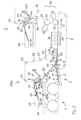
- the device 200 comprises lower rollers 31, which are at a greater distance from one another in the production direction P and also from the upper run 7 of the first circulating belt 8 than the lower rollers 21.
- the lower rollers 31 are not part of the pre-consolidation unit 22. In the system 200, this is formed by two pressure beams 32 arranged parallel to one another and perpendicularly to the production direction P of the lower rollers 21 are arranged in the system 100 and replace their function in the pre-consolidation unit 22.
- the pressure bars can be provided with plastic caps or with ceramic coatings in the areas in which they come into contact with the circulating belt 14 in order to reduce the friction with the circulating belt 14 .
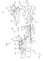
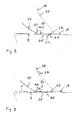
- angles ⁇ , ⁇ ' which can be between 1° and 10° in particular. like this in 4 in connection with the in 3 illustrated third embodiment of the device according to the invention (device 300) is illustrated.
- the size of the entry angle ⁇ is considerably more important for the production result than the size of the exit angle ⁇ ′, so that this can also be made considerably larger up to values greater than 90°.
- the two pressure beams 32 are replaced by pressure rollers 33.
- This configuration is recommended in particular if the pre-consolidation unit 22 is intended to apply higher pressure forces for compaction, since this can lead to an undesirable increase in the friction between the pressure bar 32 and the second circulating belt 14 in the device 200 .
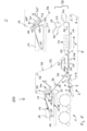
- the plant shown for producing a nonwoven web 23, which in particular can have a weight per unit area between 20 and 150 grams per square centimeter, in particular between 40 and 70 grams per square centimeter, comprises a fourth embodiment of a device (device 400) for providing a layer 13 of fibers 12, in particular short fibers with an average length of between 1 mm and 10 mm and, for example, a basis weight between 5 and 50 grams per square meter, the structure and function of which is described in detail below.
- the system also includes a carding unit 1, with which a layer 5 of long fibers, in particular a length between 10 mm and 150 mm and, for example, a basis weight between 15 and 50 grams per square centimeter can be produced.
- the carding unit 1 comprises a circulating deposit belt 2 with an upper run 3 on which the long fibers 12 can be deposited to form the layer 13 .
- the system also includes a suction roller 6, with which the layer 5 can be transferred to an upper strand 7 of a first belt 8 circulating around rollers 9 in a clockwise direction.
- the upper run 7 moves in the direction of the arrow drawn in the drawing, which thus symbolizes the production direction P.
- the first circulating belt 8 is designed to be permeable to liquids and gases, for example as a screen belt.
- the device 400 for providing the layer 13 of fibers 12 comprises a depositing belt 14 which runs around rollers 15 in a clockwise direction.
- the depositing belt 14 is in turn designed to be permeable to liquids and gases, for example as a screen belt. Due to the arrangement of the rollers 15, it forms a region 16 that rises as seen in the direction of rotation, in which the fibers 12 are deposited from a headbox 17—for example as an aqueous emulsion—to form the layer 13.
- a headbox 17 for example as an aqueous emulsion
- the delivery belt 14 also includes a region 18 which slopes down obliquely in the direction of rotation and which forms a delivery run 34 .
- the deposit belt 14 is guided over a subsequent roller 15 in a horizontal area 19 which forms a return run 35 .
- a fiber-collecting device 36 is arranged below the roller 15, on which the discharge strand 34 merges into the return strand 35.
- the device 400 also includes a take-over belt 38 which runs counterclockwise around upper rollers 37 and lower rollers 21 and has a receiving strand 39 .
- a device 40 is provided within the space delimited by the transfer belt 38, with which the receiving strand 39 is moved between a transfer position in which a part of the receiving strand 39 is at least almost in contact with the delivery strand 34 of the delivery belt 14 and at least a substantial proportion of the fibers 12 of the layer 13 is transferred from the delivery run 34 to the receiving run 39, and a rest position in which the receiving run 39 is spaced from the delivery run 34 and at least a substantial proportion of the fibers are not transferred to the receiving run.
- the resting position is illustrated in section I.
- the device 40 comprises a support structure 41 on which two guide means 42 are arranged which are spaced apart from one another in relation to the direction of rotation of the transfer belt 38 . They each include a roller 43 which bears against the receiving run 39 of the transfer belt 38 from the inside. Seen in the direction of rotation of the transfer belt 38 between the guide means 42 there is a selectively activatable suction device 44 by means of which air can be sucked through the transfer belt 38 and thus the fibers 12 or the layer 13 onto the transfer belt 38 .
- Support structure 41 is linked to a machine frame (not shown in the drawing) via linkage units 45, at least one of which is variable in length, so that device 40 moves between a position in which transfer belt 38 is in the transfer position and a position in which the transfer belt is in the rest position, can be displaced.
- the fibers 12 forming the layer 13 are not transferred to the take-over belt 38 in the rest position, but instead pass from the delivery strand 34 of the delivery belt 14 to the fiber-collecting device 36.
- the fibers 12 come into contact with the receiving strand 39, supported if necessary by the action of the suction device 44, on the take-over belt 38. From this, the fibers 12 or the layer 13 reach a lower strand 20 of the take-over belt 38, which runs between a first lower roller 46 in the production direction P and a second lower roller in the production direction P 47 is formed.
- the first lower roller 46 forms a compacting device 10 and is part of a pre-consolidation unit 22. During operation of the plant, the first lower roller 46 is in a position relative to the upper run of the first circulating belt 8 in which the distance between the lower run 20 of the transfer belt 38 and the upper strand 7 of the first circulating belt 8 is smaller than the sum of the thicknesses of the layers 5 and 13.
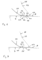
- FIG. 48 Another compacting device 10 ', which is also part of the pre-consolidation unit 22, forms a suction chamber 48. It extends parallel to the first lower 46 approximately over at least the width of the first circulating belt 8.
- the suction chamber 48 has upper, flat contact surfaces 49 on which the upper strand 7 of the first circulating band 8 rests with its underside.
- the suction chamber 48 has one or more suction openings 50 between the contact surfaces 49 .
- the suction chamber 48 is arranged in such a way that the first circulating belt 8 is pushed upwards by the suction chamber so that the upper run 7 runs parallel to the lower run 20 of the transfer belt 38 between the first lower roller 46 and the suction chamber 48 .
- the pre-consolidation unit 22 thus extends in the system 400 between the first lower roller 46 and the suction chamber 48.
- the two bands can also contact each other in the area of the pre-consolidation unit 22, in other words the distance can assume the value zero if no layer passes the pre-consolidation unit 22.
- the belts can again assume a distance due to the flexibility of the first circulating belt 8, without a displacement of the pre-consolidation unit being absolutely necessary for this.
- the first circulating belt 8 falls away from the lower strand 20 of the transfer belt 38.
- the distance between the belts 8 and 38 increases behind the suction chamber 48 before the transfer belt 38 is deflected upwards around the second lower roller 36 .
- This first embodiment of the pre-consolidation unit 22 is in 6 shown separately.
- the layer 13 is transferred to the layer 5 at a transfer point Ü, which is located in the production direction P in front of the lower roller 46 shown on the left in the drawing. Since the distance between the upper run 7 and the lower run 20 is smaller than the sum of the thicknesses of the two layers 5 and 13, the two layers experience a first flat compaction on the area between the lower rollers 46 and the suction chamber 48 Way to form a flow path 23. The size of the area depends on the distance between the first lower roller 46 and the suction chamber 48 in the production direction P.
- the first belt 8 and the transfer belt 38 must rotate at identical speeds, so that there is no friction during compacting, which could adversely affect the compacting process.
- the risk of adhesion is further reduced in that the further compacting device 10 is designed as a suction chamber 48, to which negative pressure is applied during operation of the system 400, whereby an air flow is generated through the first circulating belt 8, which prevents detachment the position 13 supported by the transfer belt 38.
- the bonding unit 22 includes a roller in the production direction P between the two lower rollers 46, 47 and Within the transfer belt 38 arranged nozzle bar 24, which forms a solidification device, and arranged in the direction of production at a corresponding point, arranged inside the first circulating belt 8 collecting device 25, which can include a suction box.
- the nozzle bar 24 On its side facing the lower strand 20, the nozzle bar 24 comprises a plurality of nozzles, from which jets of water emerge under pressure during operation of the system 1 and solidify the two layers 5 and 13 through the lower strand 20 of the transfer belt 14 by swirling fibers.
- the collecting device 25 is used to collect at least part of the water discharged from the nozzle bar 24, which can then be fed back into the production process—possibly after treatment.
- a plurality of nozzle beams 26 and collecting devices 27 are provided outside of the second circulating belt, in order to additionally solidify the layers 5 and 13 from above.
- a further solidification device 28 is provided downstream in the production direction P. It comprises two consolidation drums 29, which are rotated by the layers 5 and 13 during operation in such a way that each of the two layers is in contact with one of the two consolidation drums over an angular range of approximately 120°. Two further nozzle beams 30 are provided for each consolidation drum 29 and act in an area in which the layers 5, 13 bear against the consolidation drums 29.
- the solidification drums each have a gas- and liquid-permeable outer surface, so that at least part of the water discharged from the nozzle bar 30 during operation can be sucked off by the solidification drums and also—possibly after treatment—can be returned to the production process.
- the consolidation device 28 is used for the further consolidation of the two layers 5 and 13 to form the fleece web 23, which can be fed to further processing steps after passing through the consolidation device.
- a second embodiment of a pre-consolidation unit 22 of the fourth embodiment of the plant 400 is in 7 shown. In order to avoid repetition, only the differences from the first embodiment of the pre-consolidation unit will be described.
- the same reference symbols designate the same components.
- a pressure roller 51 is provided instead of the suction chamber 48, which is aligned parallel to the first lower roller 46, extends over the entire width of the first circulating belt 8 and presses against its upper strand 7 from below, analogous to Suction chamber 48 in the first embodiment of the preconsolidation unit 22.
- the roller 20 can be designed as a suction roller, which can be subjected to a negative pressure in order to generate an air flow through the first band 8 directed towards the surface of the suction roller.
- a third embodiment of a pre-consolidation unit 22 of the fourth embodiment of the plant 400 is in 8 shown. In order to avoid repetition, only the differences from the second embodiment of the pre-consolidation unit will be described.
- the same reference symbols designate the same components.
- a pressure roller 51 is again provided, which is aligned parallel to the first lower roller 46, extends over the entire width of the first circulating belt 8 and presses against its upper strand 7 from below.
- a suction chamber 52 is provided immediately behind this pressure roller 51 in the production direction, which does not bear against the upper run 7 of the first circulating belt 8 from below, but generates an air flow directed from top to bottom through the belt 8 by applying negative pressure and thus the detachment of the Location 13 supported by the transfer belt 38.
- the suction chamber 51 has a suction opening 53 which, seen in the production direction P, is adjacent to the pressure roller 51 .
- a detachment of the layer 13 from the transfer belt 38 in the production direction P behind the pressure roller 51 is not caused solely by the change in direction that the first circulating belt 8 experiences when passing the pressure roller 51, but is supported by the suction chamber 52. Since the first circulating belt 8 is not in contact with the suction chamber but only with the co-rotating pressure roller 52, the friction acting on the first circulating belt 8 is reduced in comparison to the first exemplary embodiment of the preconsolidation unit.
- FIG 9 the first embodiment of a pre-consolidation unit 22 of the fourth embodiment of the system 400 is shown with a modified guidance of the upper strand 7 of the first circulating belt.
- the same reference symbols designate the same components.
- the belt 8 does not change direction when passing the first lower roller 46.
- the belt 8 is guided at the 9
- the guide shown is such that the upper run 7 of the first circulating belt 8 is pressed against the transfer belt 38 in the region of the first lower roller 46 and thus undergoes a change of direction by a small angle ⁇ through the action of the roller 46.
- a carding unit 1 serves to provide the layer 5 comprising long fibers 4. It goes without saying that not only a carding unit can serve to provide such a layer, but also other devices with which a long fibers 4 comprising Location can be produced inline.
- the layer can also be generated separately, ie offline, and provided, for example, wound up into a roll. In such a case, for example, an unwinding station is provided instead of the carding unit. It is also possible to use the device according to the invention for providing fibers in a system in which only these fibers are processed into a nonwoven web, or in systems that serve to produce underlying webs.
Landscapes
- Engineering & Computer Science (AREA)
- Textile Engineering (AREA)
- Mechanical Engineering (AREA)
- Nonwoven Fabrics (AREA)
Claims (14)
- Installation (100, 200, 300, 400) de consolidation d'une couche (13) comprenant des fibres courtes (12) avec une couche (5) comprenant des fibres longues (4) en une bande de non-tissé (23),présentant une première bande (8) tournante, sur laquelle la couche (5) comprenant des fibres longues (4) peut être déposée et déplacée dans un sens de production (P) etprésentant une bande de dépôt (14) tournante, sur laquelle les fibres courtes (12) peuvent être déposées à l'aide d'une sortie de matière (17) pour la formation de la couche (13) et qui présente un brin de distribution (34),présentant une bande de transfert (38) tournante présentant un brin de réception (39), au moyen duquel la couche (13) comprenant des fibres courtes (12) peut être transmise au niveau d'un point de transition (Ü) sur la couche (5) comprenant des fibres longues (4),et présentant un dispositif (40) en liaison active avec le brin de distribution (34) ou de préférence avec le brin de réception (39), à l'aide duquel le brin de distribution (34) et le brin de réception (39) peuvent être déplacés entre une position de transfert, dans laquelle au moins une partie essentielle des fibres (12) passe du brin de distribution (34) au brin de réception (39) et continue d'avancer avec la bande de transfert (38), et une position de repos dans laquelle le brin de distribution (34) et le brin de réception (39) sont écartés l'un de l'autre et au moins une partie essentielle des fibres (12) ne passe pas au brin de réception (39) et continue d'avancer avec la bande de dépôt (14),caractérisée en ce quel'installation (100, 200, 300, 400) comprend une unité de préconsolidation (22) qui présente deux dispositifs de compactage (10, 10') écartés l'un de l'autre dans le sens de production (P), qui agissent dans une zone sur la bande de transfert (38) et forment entre eux un brin inférieur (20) de la bande de transfert (38),et présentant un dispositif de consolidation (24) agencé entre les deux dispositifs de compactage (10, 10') dans le sens de production (P),au moyen duquel les deux couches (5, 13) peuvent être consolidées l'une avec l'autre par entrelacement des longues fibres et des courtes fibres (4, 12),les dispositifs de compactage (10, 10') et le dispositif de consolidation (34) étant en liaison active les uns avec les autres de manière telle qu'ils se trouvent toujours ensemble dans un état de fonctionnement ou dans un état de repos.
- Installation selon la revendication 1, caractérisée en ce que les dispositifs de compactage (10, 10') comprennent respectivement un cylindre de pression (33).
- Installation selon la revendication 1 ou 2, caractérisée en ce que les dispositifs de compactage (10, 10') comprennent respectivement une barre de pression (32).
- Installation selon l'une quelconque des revendications 1 à 3,
caractérisée en ce que, vu dans le sens de production (P), un galet inférieur (31) entouré par la bande de transfert (38) est agencé en amont de l'unité de préconsolidation (22) et/ou, vu dans le sens de production (P), un galet inférieur (31) entouré par la bande de transfert (38) est agencé en aval de l'unité de préconsolidation (22) et en ce que, de préférence, les galets inférieurs (31) sont agencés de manière telle que la deuxième bande (14) présente, par rapport à la première bande (8), entre les galets inférieurs (31) et le dispositif de compactage (10) respectivement adjacent, un angle d'entrée (α) entre 1° et 10° et un angle de sortie (α') supérieur à 1°. - Installation selon la revendication 1, caractérisée en ce que, vu dans le sens de production (P), le premier dispositif de compactage (10) agit depuis le dessus contre le brin inférieur (20) de la bande de transfert (38) et, vu dans le sens de production (P), le deuxième dispositif de compactage (10') agit depuis le dessous contre le brin supérieur (7) de la première bande tournante (8), de sorte que la première bande tournante (8), en passant au niveau du deuxième dispositif de compactage (10'), subit une modification de direction selon un angle (β).
- Installation selon la revendication 6, caractérisée en ce que le premier dispositif de compactage (10) comprend un premier galet inférieur (46).
- Installation selon la revendication 6 ou 7, caractérisée en ce que le deuxième dispositif de compactage (10) comprend une chambre d'aspiration (48).
- Installation selon la revendication 8, caractérisée en ce que la chambre d'aspiration (48) comprend au moins une surface de contact (49) pour la première bande tournante (8) et de préférence une ouverture d'aspiration (50).
- Installation selon la revendication 6 ou 7, caractérisée en ce que le deuxième dispositif de compactage (10) présente un galet de pression (51) et en ce qu'une chambre d'aspiration (52) est située directement derrière le galet de pression (51) dans le sens de production (P).
- Installation selon l'une quelconque des revendications 1 à 10,
caractérisée en ce que le dispositif de consolidation (34) comprend une rampe de buses (24) qui est de préférence agencée à l'intérieur de la bande de transfert (38). - Installation selon l'une quelconque des revendications 1 à 11,
caractérisée en ce que le dispositif (40) comprend, dans la zone du brin de réception (39), un premier et un deuxième moyen de guidage (42) placés contre la bande de transfert (38) ou pouvant être introduits dans l'installation, pouvant être déplacés avec une composante de déplacement verticalement par rapport au brin de réception (39) et écartés l'un de l'autre dans le sens de rotation de la bande de transfert. - Installation selon la revendication 12, caractérisée en ce que le dispositif (40) comprend un mécanisme d'aspiration (44) pouvant être activé au choix, au moyen duquel la bande de transfert (38) peut être aspirée dans la zone du brin de réception (39), lequel mécanisme est de préférence disposé entre les deux moyens de guidage (42) dans le sens de rotation.
- Installation selon la revendication 12 ou 13, caractérisée en ce que le dispositif (40) présente une structure support (41) qui est agencée de manière à pouvoir être déplacée parallèlement et/ou pivotée à l'aide d'un moteur et par rapport au brin de réception (39).
- Installation selon l'une quelconque des revendications 1 à 14,caractérisée en ce qu'un mécanisme de récupération (36) des fibres, destiné à récupérer les fibres (12) qui n'ont pas été transmises au brin de réception (39), est utilisé eten ce que la bande de dépôt (14) comprend de préférence un galet de déviation (15) à l'aide duquel le brin de distribution (34) est dévié en un brin de retour (35) et le mécanisme de récupération (36) des fibres est agencé sous le galet de déviation (15).
Applications Claiming Priority (1)
| Application Number | Priority Date | Filing Date | Title |
|---|---|---|---|
| DE102021107900.4A DE102021107900B4 (de) | 2021-03-29 | 2021-03-29 | Anlage zum Verfestigen von Fasern umfassenden Lagen zu einer Vliesbahn |
Publications (3)
| Publication Number | Publication Date |
|---|---|
| EP4067548A1 EP4067548A1 (fr) | 2022-10-05 |
| EP4067548B1 true EP4067548B1 (fr) | 2023-03-22 |
| EP4067548B2 EP4067548B2 (fr) | 2026-02-18 |
Family
ID=80930213
Family Applications (1)
| Application Number | Title | Priority Date | Filing Date |
|---|---|---|---|
| EP22163578.2A Active EP4067548B2 (fr) | 2021-03-29 | 2022-03-22 | Installation de consolidation des couches comprenant des fibres en une bande de non-tissée |
Country Status (6)
| Country | Link |
|---|---|
| US (1) | US12043933B2 (fr) |
| EP (1) | EP4067548B2 (fr) |
| CN (1) | CN115142195B (fr) |
| DE (1) | DE102021107900B4 (fr) |
| FI (1) | FI4067548T4 (fr) |
| IL (1) | IL291741B2 (fr) |
Families Citing this family (2)
| Publication number | Priority date | Publication date | Assignee | Title |
|---|---|---|---|---|
| DE102019104851A1 (de) * | 2019-02-26 | 2020-08-27 | Adler Pelzer Holding Gmbh | Vorrichtung zur Herstellung von Nadelvliesen |
| EP4461859B1 (fr) * | 2023-05-10 | 2025-12-03 | Trützschler Group SE | Installation et procédé de liaison consolidation d'une bande de matière fibreuse avec un non-tissé |
Citations (18)
| Publication number | Priority date | Publication date | Assignee | Title |
|---|---|---|---|---|
| WO2001063032A1 (fr) | 2000-02-24 | 2001-08-30 | Fleissner Gmbh & Co. Maschinenfabrik | Procede et dispositif de fabrication de non-tisses composites a l'aide de l'aiguilletage hydrodynamique |
| WO2002077348A1 (fr) | 2001-03-23 | 2002-10-03 | Polymer Group Inc. | Non tisse composite |
| US20020157766A1 (en) | 1999-06-10 | 2002-10-31 | Rieter Perfojet | Process for producing a nonwoven material, plant for implementing it and nonwoven thus obtained |
| EP1126064B1 (fr) | 2000-02-15 | 2003-12-17 | GmbH & Co. Maschinenfabrik Fleissner | Dispostif de liage hydrodynamique d'une nappe fibreuse par projection d'un fluide |
| WO2004063451A1 (fr) | 2003-01-14 | 2004-07-29 | Ahlstrom Brignoud | Procede de fabrication d'un non tisse composite et installation destinee a effectuer ledit procede |
| WO2004097097A1 (fr) | 2003-05-01 | 2004-11-11 | Dan-Web Holding A/S | Procede et appareil permettant de former un tissu par voie seche |
| WO2005118934A1 (fr) | 2004-06-01 | 2005-12-15 | Dan-Web Holding A/S | Fabrication d'une etoffe multicouche |
| WO2008074665A1 (fr) | 2006-12-16 | 2008-06-26 | Oerlikon Textile Gmbh & Co. Kg | Procédé et dispositif de fabrication d'un non-tissé |
| DE102008008549A1 (de) | 2007-03-09 | 2008-09-11 | Fleissner Gmbh | Vorrichtung zum Herstellen und Verfestigen eines reinen Spinnvlieses |
| WO2008110134A1 (fr) | 2007-03-09 | 2008-09-18 | Fleissner Gmbh | Dispositif de consolidation de fibres discontinues ou d'un non-tissé constitué de filaments |
| EP1929080B1 (fr) | 2005-09-26 | 2009-04-29 | Kimberly-Clark Worldwide, Inc. | Procede de fabrication pour combiner une couche de fibres de pate a papier avec un autre substrat |
| EP2096207A1 (fr) | 2008-02-28 | 2009-09-02 | Voith Patent GmbH | Dispositif de moulage à tamis oblique d'une machine destinée à la fabrication d'une bande de matière fibreuse à partir d'au moins une suspension de matière fibreuse |
| DE102009017729A1 (de) | 2009-04-11 | 2010-10-14 | Fleissner Gmbh | Vorrichtung zum Verfestigen einer Faserbahn |
| WO2015000685A1 (fr) | 2013-07-04 | 2015-01-08 | Voith Patent Gmbh | Procédé et dispositif de fabrication de non-tissé |
| DE102013107237A1 (de) | 2013-07-09 | 2015-01-15 | TRüTZSCHLER GMBH & CO. KG | Vorrichtung und Verfahren zum hydrodynamischen Verfestigen von Vliesen, Geweben und Gewirken |
| WO2015049018A1 (fr) | 2013-10-01 | 2015-04-09 | TRüTZSCHLER GMBH & CO. KG | Précompacteur pour lisser ou compacter un ruban de fibres dans un enrouleur, enrouleur et procédé de fonctionnement d'un enrouleur |
| WO2016165798A1 (fr) | 2015-04-13 | 2016-10-20 | TRüTZSCHLER GMBH & CO. KG | Système et procédé de liaison ou de consolidation d'une bande de matière fibreuse à un non-tissé |
| EP3118361A1 (fr) | 2015-07-14 | 2017-01-18 | Trützschler GmbH & Co. KG | Installation et procede de fabrication d'un voile multicouche a partir d'au moins un voile de carde non encolle |
Family Cites Families (14)
| Publication number | Priority date | Publication date | Assignee | Title |
|---|---|---|---|---|
| GB1474120A (en) | 1974-07-16 | 1977-05-18 | Honshu Paper Co Ltd | Multilayer fibrous web |
| DE19827567A1 (de) | 1998-06-20 | 1999-12-23 | Corovin Gmbh | Verfahren zur Herstellung eines Vlieses aus Fasern |
| FR2803604B1 (fr) * | 2000-01-11 | 2002-03-08 | Icbt Perfojet Sa | Procede pour la realisation d'un materiau non tisse complexe et nouveau type de materiau ainsi obtenu |
| WO2002050354A1 (fr) * | 2000-12-19 | 2002-06-27 | M & J Fibretech A/S | Procede et equipement de production sans bande de base d'une bande de fibres hydro-enchevetrees air-laid |
| DE10254563A1 (de) | 2002-11-21 | 2004-06-03 | Fleissner Gmbh & Co. Maschinenfabrik | Vorrichtung zum hydrodynamischen Verschlingen der Fasern einer Faserbahn |
| US20050091811A1 (en) * | 2003-10-31 | 2005-05-05 | Sca Hygiene Products Ab | Method of producing a nonwoven material |
| FR2870263B1 (fr) | 2004-05-11 | 2006-07-07 | Rieter Perfojet Sa | Nontisse large et ses procedes et machine de fabrication |
| US7278187B2 (en) * | 2004-08-27 | 2007-10-09 | Dan-Web Holding A/S | Manufacture of a multi-layer fabric |
| FR2911616B1 (fr) | 2007-01-19 | 2009-07-03 | Rieter Perfojet Soc Par Action | Installation et procede de production d'une nappe a base de fibres ou de filaments |
| DE102008031278A1 (de) * | 2007-07-12 | 2009-01-15 | Fleissner Gmbh | Vorrichtung zur Kompaktierung eines saugfähigen Produkts wiw Papier bzw. Tissue mit Hilfe einer Wasservernadelungseinrichtung oder Dampfvernadelungseinrichtung |
| WO2009112008A1 (fr) * | 2008-03-12 | 2009-09-17 | Fleissner Gmbh | Procédé et dispositif pour la présolidification d'un non-tissé |
| ES2404904T3 (es) | 2009-04-08 | 2013-05-29 | Trützschler Nonwovens Gmbh | Dispositivo para la consolidación de una banda de fibras |
| DE102015001008A1 (de) | 2015-01-28 | 2016-07-28 | Andritz Küsters Gmbh | Verfahren und Vorrichtung zur Herstellung von nassgelegten Vliesstoffen |
| DE102015106490B3 (de) * | 2015-04-28 | 2016-09-29 | TRüTZSCHLER GMBH & CO. KG | Anlage und Verfahren zur Verfestigung und Strukturierung von Fasern zu einem Vlies |
-
2021
- 2021-03-29 DE DE102021107900.4A patent/DE102021107900B4/de active Active
-
2022
- 2022-03-22 FI FIEP22163578.2T patent/FI4067548T4/fi active
- 2022-03-22 EP EP22163578.2A patent/EP4067548B2/fr active Active
- 2022-03-24 US US17/702,816 patent/US12043933B2/en active Active
- 2022-03-27 IL IL291741A patent/IL291741B2/en unknown
- 2022-03-29 CN CN202210319787.2A patent/CN115142195B/zh active Active
Patent Citations (21)
| Publication number | Priority date | Publication date | Assignee | Title |
|---|---|---|---|---|
| US20020157766A1 (en) | 1999-06-10 | 2002-10-31 | Rieter Perfojet | Process for producing a nonwoven material, plant for implementing it and nonwoven thus obtained |
| DE60030120T2 (de) | 1999-06-10 | 2007-02-15 | Rieter Perfojet | Verfahren zur herstellung eines vliesstoffes, anlage zur durchführung dieses verfahren, hergestellter vliesstoff |
| EP1126064B1 (fr) | 2000-02-15 | 2003-12-17 | GmbH & Co. Maschinenfabrik Fleissner | Dispostif de liage hydrodynamique d'une nappe fibreuse par projection d'un fluide |
| WO2001063032A1 (fr) | 2000-02-24 | 2001-08-30 | Fleissner Gmbh & Co. Maschinenfabrik | Procede et dispositif de fabrication de non-tisses composites a l'aide de l'aiguilletage hydrodynamique |
| WO2002077348A1 (fr) | 2001-03-23 | 2002-10-03 | Polymer Group Inc. | Non tisse composite |
| WO2004063451A1 (fr) | 2003-01-14 | 2004-07-29 | Ahlstrom Brignoud | Procede de fabrication d'un non tisse composite et installation destinee a effectuer ledit procede |
| DE602004008578T2 (de) | 2003-01-14 | 2008-05-21 | Ahlstrom Corp. | Verfahren zur herstellung eines verbundvliesstoffs sowie anlage zur durchführung des verfahrens |
| WO2004097097A1 (fr) | 2003-05-01 | 2004-11-11 | Dan-Web Holding A/S | Procede et appareil permettant de former un tissu par voie seche |
| WO2005118934A1 (fr) | 2004-06-01 | 2005-12-15 | Dan-Web Holding A/S | Fabrication d'une etoffe multicouche |
| EP1929080B1 (fr) | 2005-09-26 | 2009-04-29 | Kimberly-Clark Worldwide, Inc. | Procede de fabrication pour combiner une couche de fibres de pate a papier avec un autre substrat |
| WO2008074665A1 (fr) | 2006-12-16 | 2008-06-26 | Oerlikon Textile Gmbh & Co. Kg | Procédé et dispositif de fabrication d'un non-tissé |
| DE102008008549A1 (de) | 2007-03-09 | 2008-09-11 | Fleissner Gmbh | Vorrichtung zum Herstellen und Verfestigen eines reinen Spinnvlieses |
| WO2008110134A1 (fr) | 2007-03-09 | 2008-09-18 | Fleissner Gmbh | Dispositif de consolidation de fibres discontinues ou d'un non-tissé constitué de filaments |
| EP2096207A1 (fr) | 2008-02-28 | 2009-09-02 | Voith Patent GmbH | Dispositif de moulage à tamis oblique d'une machine destinée à la fabrication d'une bande de matière fibreuse à partir d'au moins une suspension de matière fibreuse |
| DE102009017729A1 (de) | 2009-04-11 | 2010-10-14 | Fleissner Gmbh | Vorrichtung zum Verfestigen einer Faserbahn |
| WO2015000685A1 (fr) | 2013-07-04 | 2015-01-08 | Voith Patent Gmbh | Procédé et dispositif de fabrication de non-tissé |
| DE102013107237A1 (de) | 2013-07-09 | 2015-01-15 | TRüTZSCHLER GMBH & CO. KG | Vorrichtung und Verfahren zum hydrodynamischen Verfestigen von Vliesen, Geweben und Gewirken |
| WO2015049018A1 (fr) | 2013-10-01 | 2015-04-09 | TRüTZSCHLER GMBH & CO. KG | Précompacteur pour lisser ou compacter un ruban de fibres dans un enrouleur, enrouleur et procédé de fonctionnement d'un enrouleur |
| WO2016165798A1 (fr) | 2015-04-13 | 2016-10-20 | TRüTZSCHLER GMBH & CO. KG | Système et procédé de liaison ou de consolidation d'une bande de matière fibreuse à un non-tissé |
| EP3283679B1 (fr) | 2015-04-13 | 2020-11-25 | Trützschler GmbH & Co. KG | Système et procédé de liaison ou de consolidation d'une bande de matière fibreuse à un non-tissé |
| EP3118361A1 (fr) | 2015-07-14 | 2017-01-18 | Trützschler GmbH & Co. KG | Installation et procede de fabrication d'un voile multicouche a partir d'au moins un voile de carde non encolle |
Non-Patent Citations (1)
| Title |
|---|
| S.J. RUSSELL: "Handbook of Nonwoven", 22 December 2006, CRS PRESS, Cambridge, England, ISBN: 978-0-8493-2596-0, article A.G. BRYDON AND A. POURMOHAMMADI: "2 - Dry-laid web formation", pages: 16 - 111, XP009555995, DOI: 10.1533/9781845691998.16 |
Also Published As
| Publication number | Publication date |
|---|---|
| FI4067548T3 (fi) | 2023-06-21 |
| CN115142195B (zh) | 2024-05-10 |
| DE102021107900A1 (de) | 2022-09-29 |
| FI4067548T4 (fi) | 2026-03-30 |
| EP4067548A1 (fr) | 2022-10-05 |
| IL291741B1 (en) | 2024-08-01 |
| CN115142195A (zh) | 2022-10-04 |
| US12043933B2 (en) | 2024-07-23 |
| IL291741A (en) | 2022-10-01 |
| US20220307176A1 (en) | 2022-09-29 |
| IL291741B2 (en) | 2024-12-01 |
| DE102021107900B4 (de) | 2023-02-02 |
| EP4067548B2 (fr) | 2026-02-18 |
Similar Documents
| Publication | Publication Date | Title |
|---|---|---|
| DE69711931T2 (de) | Anlage zur herstellung von einem nicht gewebten faserprodukt | |
| DE69409648T3 (de) | Dispositif pour detacher et transporter à grande vitesse un voile fibreux en sortie de carde | |
| EP1870499B1 (fr) | Etaleur-nappeur | |
| EP3118361B1 (fr) | Installation et procede de fabrication d'un voile multicouche a partir d'au moins un voile de carde non encolle | |
| EP1967628A1 (fr) | Procédé et dispositif de fabrication d'un textile non-tissé filé-lié | |
| EP3061855B1 (fr) | Installation de carde et procede de renforcement d'un voile de carde | |
| EP4067548B2 (fr) | Installation de consolidation des couches comprenant des fibres en une bande de non-tissée | |
| CH678193A5 (fr) | ||
| EP4149751B1 (fr) | Système de production d'un non-tissé multicouche et procédé de production d'un non-tissé | |
| EP4067550B1 (fr) | Installation de renforcement d'au moins une couche fibreuse déposée à l'état humide ou sec en une bande non tissée | |
| DE102008008549A1 (de) | Vorrichtung zum Herstellen und Verfestigen eines reinen Spinnvlieses | |
| DE10105843A1 (de) | Verfahren und Vorrichtung zum Transport eines Vlieses zwischen zwei mit Abstand voneinander angeordneten Walzen | |
| EP0522093B1 (fr) | Procede et dispositif pour le nettoyage d'une toile sans fin de machine a papier | |
| DE19511904B4 (de) | Anlage und Verfahren zur Herstellung von Vliesbahnen | |
| DE10146907A1 (de) | Vlieszuführvorrichtung | |
| WO2008110134A1 (fr) | Dispositif de consolidation de fibres discontinues ou d'un non-tissé constitué de filaments | |
| EP4067549B1 (fr) | Installation et procédé de consolidation des couches comprenant des fibres en une bande de non-tissé | |
| EP4267389B1 (fr) | Dispositif de fabrication d'une bande de tissu non-tissé composite | |
| EP2539498B1 (fr) | Dispositif de consolidation d'une bande de matériau | |
| DE60304367T2 (de) | Verfahren und vorrichtung zur stabilisierung von rändern eines vliesstoffes | |
| EP4001488B1 (fr) | Dispositif de fabrication de tissus non tissés à partir de filaments continus | |
| DE4234355A1 (de) | Verfahren und Vorrichtung zum Herstellen einer Filzbahn großer Breite | |
| DE4434402A1 (de) | Vorrichtung zur Umformung eines großformatigen Faservlieses zu einem Faserband | |
| DE102020130593A1 (de) | Vorrichtung zur Herstellung von Vliesstoffen aus Endlosfilamenten | |
| EP4619577A1 (fr) | Installation de traitement de fibres et procédé de traitement de fibres |
Legal Events
| Date | Code | Title | Description |
|---|---|---|---|
| PUAI | Public reference made under article 153(3) epc to a published international application that has entered the european phase |
Free format text: ORIGINAL CODE: 0009012 |
|
| STAA | Information on the status of an ep patent application or granted ep patent |
Free format text: STATUS: THE APPLICATION HAS BEEN PUBLISHED |
|
| STAA | Information on the status of an ep patent application or granted ep patent |
Free format text: STATUS: REQUEST FOR EXAMINATION WAS MADE |
|
| AK | Designated contracting states |
Kind code of ref document: A1 Designated state(s): AL AT BE BG CH CY CZ DE DK EE ES FI FR GB GR HR HU IE IS IT LI LT LU LV MC MK MT NL NO PL PT RO RS SE SI SK SM TR |
|
| 17P | Request for examination filed |
Effective date: 20220907 |
|
| RBV | Designated contracting states (corrected) |
Designated state(s): AL AT BE BG CH CY CZ DE DK EE ES FI FR GB GR HR HU IE IS IT LI LT LU LV MC MK MT NL NO PL PT RO RS SE SI SK SM TR |
|
| GRAP | Despatch of communication of intention to grant a patent |
Free format text: ORIGINAL CODE: EPIDOSNIGR1 |
|
| STAA | Information on the status of an ep patent application or granted ep patent |
Free format text: STATUS: GRANT OF PATENT IS INTENDED |
|
| INTG | Intention to grant announced |
Effective date: 20221128 |
|
| GRAS | Grant fee paid |
Free format text: ORIGINAL CODE: EPIDOSNIGR3 |
|
| GRAA | (expected) grant |
Free format text: ORIGINAL CODE: 0009210 |
|
| STAA | Information on the status of an ep patent application or granted ep patent |
Free format text: STATUS: THE PATENT HAS BEEN GRANTED |
|
| AK | Designated contracting states |
Kind code of ref document: B1 Designated state(s): AL AT BE BG CH CY CZ DE DK EE ES FI FR GB GR HR HU IE IS IT LI LT LU LV MC MK MT NL NO PL PT RO RS SE SI SK SM TR |
|
| REG | Reference to a national code |
Ref country code: GB Ref legal event code: FG4D Free format text: NOT ENGLISH |
|
| REG | Reference to a national code |
Ref country code: CH Ref legal event code: EP |
|
| REG | Reference to a national code |
Ref country code: IE Ref legal event code: FG4D Free format text: LANGUAGE OF EP DOCUMENT: GERMAN |
|
| REG | Reference to a national code |
Ref country code: DE Ref legal event code: R096 Ref document number: 502022000007 Country of ref document: DE |
|
| REG | Reference to a national code |
Ref country code: AT Ref legal event code: REF Ref document number: 1555344 Country of ref document: AT Kind code of ref document: T Effective date: 20230415 |
|
| REG | Reference to a national code |
Ref country code: FI Ref legal event code: FGE |
|
| P01 | Opt-out of the competence of the unified patent court (upc) registered |
Effective date: 20230524 |
|
| REG | Reference to a national code |
Ref country code: LT Ref legal event code: MG9D |
|
| REG | Reference to a national code |
Ref country code: NL Ref legal event code: MP Effective date: 20230322 |
|
| PG25 | Lapsed in a contracting state [announced via postgrant information from national office to epo] |
Ref country code: RS Free format text: LAPSE BECAUSE OF FAILURE TO SUBMIT A TRANSLATION OF THE DESCRIPTION OR TO PAY THE FEE WITHIN THE PRESCRIBED TIME-LIMIT Effective date: 20230322 Ref country code: NO Free format text: LAPSE BECAUSE OF FAILURE TO SUBMIT A TRANSLATION OF THE DESCRIPTION OR TO PAY THE FEE WITHIN THE PRESCRIBED TIME-LIMIT Effective date: 20230622 Ref country code: LV Free format text: LAPSE BECAUSE OF FAILURE TO SUBMIT A TRANSLATION OF THE DESCRIPTION OR TO PAY THE FEE WITHIN THE PRESCRIBED TIME-LIMIT Effective date: 20230322 Ref country code: LT Free format text: LAPSE BECAUSE OF FAILURE TO SUBMIT A TRANSLATION OF THE DESCRIPTION OR TO PAY THE FEE WITHIN THE PRESCRIBED TIME-LIMIT Effective date: 20230322 Ref country code: HR Free format text: LAPSE BECAUSE OF FAILURE TO SUBMIT A TRANSLATION OF THE DESCRIPTION OR TO PAY THE FEE WITHIN THE PRESCRIBED TIME-LIMIT Effective date: 20230322 |
|
| PG25 | Lapsed in a contracting state [announced via postgrant information from national office to epo] |
Ref country code: SE Free format text: LAPSE BECAUSE OF FAILURE TO SUBMIT A TRANSLATION OF THE DESCRIPTION OR TO PAY THE FEE WITHIN THE PRESCRIBED TIME-LIMIT Effective date: 20230322 Ref country code: NL Free format text: LAPSE BECAUSE OF FAILURE TO SUBMIT A TRANSLATION OF THE DESCRIPTION OR TO PAY THE FEE WITHIN THE PRESCRIBED TIME-LIMIT Effective date: 20230322 Ref country code: GR Free format text: LAPSE BECAUSE OF FAILURE TO SUBMIT A TRANSLATION OF THE DESCRIPTION OR TO PAY THE FEE WITHIN THE PRESCRIBED TIME-LIMIT Effective date: 20230623 |
|
| PG25 | Lapsed in a contracting state [announced via postgrant information from national office to epo] |
Ref country code: SM Free format text: LAPSE BECAUSE OF FAILURE TO SUBMIT A TRANSLATION OF THE DESCRIPTION OR TO PAY THE FEE WITHIN THE PRESCRIBED TIME-LIMIT Effective date: 20230322 Ref country code: RO Free format text: LAPSE BECAUSE OF FAILURE TO SUBMIT A TRANSLATION OF THE DESCRIPTION OR TO PAY THE FEE WITHIN THE PRESCRIBED TIME-LIMIT Effective date: 20230322 Ref country code: PT Free format text: LAPSE BECAUSE OF FAILURE TO SUBMIT A TRANSLATION OF THE DESCRIPTION OR TO PAY THE FEE WITHIN THE PRESCRIBED TIME-LIMIT Effective date: 20230724 Ref country code: ES Free format text: LAPSE BECAUSE OF FAILURE TO SUBMIT A TRANSLATION OF THE DESCRIPTION OR TO PAY THE FEE WITHIN THE PRESCRIBED TIME-LIMIT Effective date: 20230322 Ref country code: EE Free format text: LAPSE BECAUSE OF FAILURE TO SUBMIT A TRANSLATION OF THE DESCRIPTION OR TO PAY THE FEE WITHIN THE PRESCRIBED TIME-LIMIT Effective date: 20230322 |
|
| PG25 | Lapsed in a contracting state [announced via postgrant information from national office to epo] |
Ref country code: SK Free format text: LAPSE BECAUSE OF FAILURE TO SUBMIT A TRANSLATION OF THE DESCRIPTION OR TO PAY THE FEE WITHIN THE PRESCRIBED TIME-LIMIT Effective date: 20230322 Ref country code: PL Free format text: LAPSE BECAUSE OF FAILURE TO SUBMIT A TRANSLATION OF THE DESCRIPTION OR TO PAY THE FEE WITHIN THE PRESCRIBED TIME-LIMIT Effective date: 20230322 Ref country code: IS Free format text: LAPSE BECAUSE OF FAILURE TO SUBMIT A TRANSLATION OF THE DESCRIPTION OR TO PAY THE FEE WITHIN THE PRESCRIBED TIME-LIMIT Effective date: 20230722 |
|
| REG | Reference to a national code |
Ref country code: DE Ref legal event code: R026 Ref document number: 502022000007 Country of ref document: DE |
|
| PLBI | Opposition filed |
Free format text: ORIGINAL CODE: 0009260 |
|
| PLAX | Notice of opposition and request to file observation + time limit sent |
Free format text: ORIGINAL CODE: EPIDOSNOBS2 |
|
| 26 | Opposition filed |
Opponent name: TRUETZSCHLER GROUP SE Effective date: 20231213 |
|
| PG25 | Lapsed in a contracting state [announced via postgrant information from national office to epo] |
Ref country code: MC Free format text: LAPSE BECAUSE OF FAILURE TO SUBMIT A TRANSLATION OF THE DESCRIPTION OR TO PAY THE FEE WITHIN THE PRESCRIBED TIME-LIMIT Effective date: 20230322 |
|
| PG25 | Lapsed in a contracting state [announced via postgrant information from national office to epo] |
Ref country code: SI Free format text: LAPSE BECAUSE OF FAILURE TO SUBMIT A TRANSLATION OF THE DESCRIPTION OR TO PAY THE FEE WITHIN THE PRESCRIBED TIME-LIMIT Effective date: 20230322 Ref country code: MC Free format text: LAPSE BECAUSE OF FAILURE TO SUBMIT A TRANSLATION OF THE DESCRIPTION OR TO PAY THE FEE WITHIN THE PRESCRIBED TIME-LIMIT Effective date: 20230322 Ref country code: DK Free format text: LAPSE BECAUSE OF FAILURE TO SUBMIT A TRANSLATION OF THE DESCRIPTION OR TO PAY THE FEE WITHIN THE PRESCRIBED TIME-LIMIT Effective date: 20230322 Ref country code: CZ Free format text: LAPSE BECAUSE OF FAILURE TO SUBMIT A TRANSLATION OF THE DESCRIPTION OR TO PAY THE FEE WITHIN THE PRESCRIBED TIME-LIMIT Effective date: 20230322 |
|
| PLBB | Reply of patent proprietor to notice(s) of opposition received |
Free format text: ORIGINAL CODE: EPIDOSNOBS3 |
|
| PG25 | Lapsed in a contracting state [announced via postgrant information from national office to epo] |
Ref country code: BG Free format text: LAPSE BECAUSE OF FAILURE TO SUBMIT A TRANSLATION OF THE DESCRIPTION OR TO PAY THE FEE WITHIN THE PRESCRIBED TIME-LIMIT Effective date: 20230322 |
|
| PG25 | Lapsed in a contracting state [announced via postgrant information from national office to epo] |
Ref country code: LU Free format text: LAPSE BECAUSE OF NON-PAYMENT OF DUE FEES Effective date: 20240322 |
|
| PG25 | Lapsed in a contracting state [announced via postgrant information from national office to epo] |
Ref country code: LU Free format text: LAPSE BECAUSE OF NON-PAYMENT OF DUE FEES Effective date: 20240322 Ref country code: BG Free format text: LAPSE BECAUSE OF FAILURE TO SUBMIT A TRANSLATION OF THE DESCRIPTION OR TO PAY THE FEE WITHIN THE PRESCRIBED TIME-LIMIT Effective date: 20230322 |
|
| REG | Reference to a national code |
Ref country code: BE Ref legal event code: MM Effective date: 20240331 |
|
| PG25 | Lapsed in a contracting state [announced via postgrant information from national office to epo] |
Ref country code: BE Free format text: LAPSE BECAUSE OF NON-PAYMENT OF DUE FEES Effective date: 20240331 |
|
| PG25 | Lapsed in a contracting state [announced via postgrant information from national office to epo] |
Ref country code: IE Free format text: LAPSE BECAUSE OF NON-PAYMENT OF DUE FEES Effective date: 20240322 |
|
| PG25 | Lapsed in a contracting state [announced via postgrant information from national office to epo] |
Ref country code: IE Free format text: LAPSE BECAUSE OF NON-PAYMENT OF DUE FEES Effective date: 20240322 Ref country code: BE Free format text: LAPSE BECAUSE OF NON-PAYMENT OF DUE FEES Effective date: 20240331 |
|
| PGFP | Annual fee paid to national office [announced via postgrant information from national office to epo] |
Ref country code: IT Payment date: 20250331 Year of fee payment: 4 |
|
| PG25 | Lapsed in a contracting state [announced via postgrant information from national office to epo] |
Ref country code: CY Free format text: LAPSE BECAUSE OF FAILURE TO SUBMIT A TRANSLATION OF THE DESCRIPTION OR TO PAY THE FEE WITHIN THE PRESCRIBED TIME-LIMIT; INVALID AB INITIO Effective date: 20220322 |
|
| REG | Reference to a national code |
Ref country code: CH Ref legal event code: H13 Free format text: ST27 STATUS EVENT CODE: U-0-0-H10-H13 (AS PROVIDED BY THE NATIONAL OFFICE) Effective date: 20251024 |
|
| PUAH | Patent maintained in amended form |
Free format text: ORIGINAL CODE: 0009272 |
|
| STAA | Information on the status of an ep patent application or granted ep patent |
Free format text: STATUS: PATENT MAINTAINED AS AMENDED |
|
| PG25 | Lapsed in a contracting state [announced via postgrant information from national office to epo] |
Ref country code: CH Free format text: LAPSE BECAUSE OF NON-PAYMENT OF DUE FEES Effective date: 20250331 |
|
| REG | Reference to a national code |
Ref country code: CH Ref legal event code: M12 Free format text: ST27 STATUS EVENT CODE: U-0-0-M10-M12 (AS PROVIDED BY THE NATIONAL OFFICE) Effective date: 20260121 |
|
| 27A | Patent maintained in amended form |
Effective date: 20260218 |
|
| AK | Designated contracting states |
Kind code of ref document: B2 Designated state(s): AL AT BE BG CH CY CZ DE DK EE ES FI FR GB GR HR HU IE IS IT LI LT LU LV MC MK MT NL NO PL PT RO RS SE SI SK SM TR |
|
| REG | Reference to a national code |
Ref country code: DE Ref legal event code: R102 Ref document number: 502022000007 Country of ref document: DE |
|
| PGFP | Annual fee paid to national office [announced via postgrant information from national office to epo] |
Ref country code: DE Payment date: 20260219 Year of fee payment: 5 |
|
| PGFP | Annual fee paid to national office [announced via postgrant information from national office to epo] |
Ref country code: AT Payment date: 20260301 Year of fee payment: 5 |
|
| PGFP | Annual fee paid to national office [announced via postgrant information from national office to epo] |
Ref country code: FI Payment date: 20260320 Year of fee payment: 5 |
|
| PGFP | Annual fee paid to national office [announced via postgrant information from national office to epo] |
Ref country code: FR Payment date: 20260325 Year of fee payment: 5 |
|
| PGFP | Annual fee paid to national office [announced via postgrant information from national office to epo] |
Ref country code: TR Payment date: 20260316 Year of fee payment: 5 |