EP4067554B1 - Balanceanordnung und haushaltsgerät - Google Patents
Balanceanordnung und haushaltsgerät Download PDFInfo
- Publication number
- EP4067554B1 EP4067554B1 EP20910335.7A EP20910335A EP4067554B1 EP 4067554 B1 EP4067554 B1 EP 4067554B1 EP 20910335 A EP20910335 A EP 20910335A EP 4067554 B1 EP4067554 B1 EP 4067554B1
- Authority
- EP
- European Patent Office
- Prior art keywords
- balancer
- detection
- detection member
- balance assembly
- chamber
- Prior art date
- Legal status (The legal status is an assumption and is not a legal conclusion. Google has not performed a legal analysis and makes no representation as to the accuracy of the status listed.)
- Active
Links
Images



Classifications
-
- D—TEXTILES; PAPER
- D06—TREATMENT OF TEXTILES OR THE LIKE; LAUNDERING; FLEXIBLE MATERIALS NOT OTHERWISE PROVIDED FOR
- D06F—LAUNDERING, DRYING, IRONING, PRESSING OR FOLDING TEXTILE ARTICLES
- D06F37/00—Details specific to washing machines covered by groups D06F21/00 - D06F25/00
- D06F37/20—Mountings, e.g. resilient mountings, for the rotary receptacle, motor, tub or casing; Preventing or damping vibrations
- D06F37/22—Mountings, e.g. resilient mountings, for the rotary receptacle, motor, tub or casing; Preventing or damping vibrations in machines with a receptacle rotating or oscillating about a horizontal axis
-
- D—TEXTILES; PAPER
- D06—TREATMENT OF TEXTILES OR THE LIKE; LAUNDERING; FLEXIBLE MATERIALS NOT OTHERWISE PROVIDED FOR
- D06F—LAUNDERING, DRYING, IRONING, PRESSING OR FOLDING TEXTILE ARTICLES
- D06F33/00—Control of operations performed in washing machines or washer-dryers
- D06F33/30—Control of washing machines characterised by the purpose or target of the control
- D06F33/48—Preventing or reducing imbalance or noise
-
- D—TEXTILES; PAPER
- D06—TREATMENT OF TEXTILES OR THE LIKE; LAUNDERING; FLEXIBLE MATERIALS NOT OTHERWISE PROVIDED FOR
- D06F—LAUNDERING, DRYING, IRONING, PRESSING OR FOLDING TEXTILE ARTICLES
- D06F33/00—Control of operations performed in washing machines or washer-dryers
- D06F33/50—Control of washer-dryers characterised by the purpose or target of the control
- D06F33/76—Preventing or reducing imbalance or noise
-
- D—TEXTILES; PAPER
- D06—TREATMENT OF TEXTILES OR THE LIKE; LAUNDERING; FLEXIBLE MATERIALS NOT OTHERWISE PROVIDED FOR
- D06F—LAUNDERING, DRYING, IRONING, PRESSING OR FOLDING TEXTILE ARTICLES
- D06F37/00—Details specific to washing machines covered by groups D06F21/00 - D06F25/00
- D06F37/20—Mountings, e.g. resilient mountings, for the rotary receptacle, motor, tub or casing; Preventing or damping vibrations
- D06F37/22—Mountings, e.g. resilient mountings, for the rotary receptacle, motor, tub or casing; Preventing or damping vibrations in machines with a receptacle rotating or oscillating about a horizontal axis
- D06F37/225—Damping vibrations by displacing, supplying or ejecting a material, e.g. liquid, into or from counterbalancing pockets
-
- D—TEXTILES; PAPER
- D06—TREATMENT OF TEXTILES OR THE LIKE; LAUNDERING; FLEXIBLE MATERIALS NOT OTHERWISE PROVIDED FOR
- D06F—LAUNDERING, DRYING, IRONING, PRESSING OR FOLDING TEXTILE ARTICLES
- D06F2103/00—Parameters monitored or detected for the control of domestic laundry washing machines, washer-dryers or laundry dryers
- D06F2103/26—Imbalance; Noise level
Definitions
- the present invention relates to the field of household appliances, and more particularly, to a balance assembly and a household appliance.
- EP 2 955 263 A1 relates generally to a laundry machine equipped with a balancing unit.
- the invention is defined by a balance assembly according to independent claim 1. Preferred embodiments of the present invention are set out in the dependent claims.
- the present invention provides a balance assembly applied in a household appliance.
- the balance assembly includes a balancing ring, a balancer, an identification member, and a first detection member.
- the balancing ring has a chamber defined therein.
- the balancer is movably arranged in the chamber, and includes a rotating member and a driving member.
- the driving member is connected to the rotating member and is configured to drive the rotating member to rotate to drive a movement of the balancer within the chamber.
- the balance assembly is configured to cause a relative movement between the identification member and the first detection member during the movement of the balancer.
- the first detection member is configured to detect a number of times of the identification member passing through the first detection member. The number of times of the identification member passing through the first detection member is related to a position of the balancer.
- the rotating member can drive the movement of the balancer in the chamber.
- the first detection member can detect the number of times of the identification member passing through the first detection member, and the number of times of the identification member passing through the first detection member can be used to determine the position of the balancer.
- the identification member is disposed on the rotating member.
- the rotating member includes a gear; the chamber includes a first inner wall having a ring gear portion disposed thereon, the gear meshing with the ring gear portion; and the identification member is a tooth of the gear or a tooth of the ring gear portion.
- the first detection member includes at least one of an optical sensor, a Hall sensor, or an ultrasonic sensor.
- the balance assembly further includes a controller electrically connected to the first detection member; the chamber has an initial position; the controller is configured to determine a position of the balancer based on the initial position and the number of times of the identification member passing through the first detection member.
- the balance assembly further includes a first guide member disposed on the balancer, and a second guide member.
- the chamber includes a first inner wall, and a second inner wall opposite to the first inner wall.
- the second guide member is disposed on the second inner wall.
- the first guide member is connected to the second guide member to guide the movement of the balancer.
- the first guide includes a roller connected to the second guide member.
- the balance assembly further includes a calibration member and a second detection member.
- the balance assembly is configured to cause a relative movement between the calibration member and the second detection member during the movement of the balancer and cause the second detection member to detect the calibration member for eliminating a position error of the balancer.
- the first detection member and the second detection member are both disposed on the balancer; the identification member is disposed on the rotating member; the calibration member is arranged on an inner wall of the chamber.
- Embodiments of the present disclosure provide a household appliance.
- the household appliance includes a cavity having a rotation axis, and the balance assembly according to any one of the above embodiments.
- the balance assembly is mounted in the cavity.
- a central axis of the balancing ring is parallel to or coincident with the rotation axis of the cavity.
- the rotating member can drive the movement of the balancer within the chamber.
- the first detection member can detect the number of times of the identification member passing through the first detection member, and the number of times of the identification member passing through the first detection member can be used to determine the position of the balancer.
- first and second are used herein for purposes of description and are not intended to indicate or imply relative importance, or to implicitly show a number of technical features indicated. Thus, a feature defined with “first” and “second” may explicitly or implicitly comprise one or more this feature. In the description of the present disclosure, "a plurality of” means two or more, unless specified otherwise.
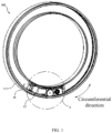
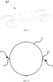
- the balance assembly 100 includes a balancing ring 11, a balancer 13, an identification member 15, and a first detection member 17.
- the balancing ring 11 has a chamber 19 defined therein.
- the balancer 13 is movably arranged in the chamber 19 and includes a rotating member 21 and a driving member 23.
- the driving member 23 is connected to the rotating member 21 and is configured to drive the rotating member 21 to rotate to drive a movement of the balancer 13 within the chamber 19.
- the balance assembly 100 is configured to cause a relative movement between the identification member 15 and the first detection member 17 during the movement of the balancer 13.
- the first detection member 17 is configured to detect a number of times of the identification member 15 passing through the first detection member 17, and the number of times of the identification member 15 passing through the first detection member 17 is related to a position of the balancer 13.
- the rotating member 21 may drive a movement of the balancer 13 within the chamber 19.
- the first detection member 17 may detect the number of times of the identification member 15 passing through the first detection member 17, and the number of times of the identification member 15 passing through the first detection member 17 may be used to determine the position of the balancer 13.
- the identification member 15 and the first detection member 17 move relative to each other, and the identification member 15 passes through the first detection member 17.
- the number of times of the identification member 15 passing through the first detection member 17 is related to the position of the balancer 13. Therefore, the moving distance of the balancer 13 may be determined by detecting the number of times of the identification member 15 passing through the first detection member 17, and the position of the balancer 13 may be determined in combination with an initial position 191 of the balancer 13.
- the initial position 191 may refer to a position where the balancer 13 is located before it begins to move within the chamber 19, or a certain position that can be determined during the movement of the balancer 13.
- the balancing ring 11 defines a chamber 19 along the circumferential direction, and the balancer 13 may move back and forth within the chamber 19 along the circumferential direction. That is, the balancer 13 may make a circular motion in the chamber 19 of the balancing ring 11.
- the driving member 23 is connected to the rotating member 21, and the driving member 23 drives the rotating member 21 to rotate on the inner wall of the chamber 19, so as to drive a movement of the balancer 13 within the chamber 19.
- the rotating member 21 has an identification member 15 disposed thereon.
- the chamber 19 has an identification member 15 disposed on an inner wall thereof. In this way, the identification member 15 can be detected in various manners, and thus the flexibility of the identification member 15 during mounting can be improved.
- the identification member 15 is disposed on the rotating member 21.
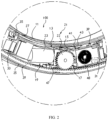
- the rotating member 21 includes a gear 22.
- the chamber 19 includes a first inner wall 25, and the first inner wall 25 has a ring gear portion 29 disposed thereon.
- the gear 22 meshes with the ring gear portion 29.
- the identification member 15 is a tooth of the gear 22 or a tooth of the ring gear portion 29. In this way, the tooth of the gear 22 can be used as the identification member 15, without requiring a separate identification member 15. It can be understood that, in other embodiments, the identification member 15 may also be the tooth of the ring gear portion 29.
- the gear 22 meshes with the ring gear portion 29 to rotate.
- the balancer 13 may be driven to move relative to the ring gear portion 29.
- the teeth of the gear 22 or the teeth of the ring gear portion 29 may serve as the identification member 15, and correspondingly, the first detection member 17 may be mounted on the balancer 13.
- the first detection member 17 includes a detection surface, and the detection surface faces the identification member 15.
- the first inner wall 25 of the chamber 19 has the identification member 15.
- the identification member 15 may be disposed in a position other than the first inner wall 25 in the chamber 19.
- the first detection member 17 may be mounted on the balancer 13 at a position directly facing the tooth of the gear 22.
- the first detection member 17 is relatively stationary.
- the identification member 15 is the tooth of the ring gear portion 29.
- the first detection member 17 may be mounted on the balancer 13 at a position directly facing the tooth of the ring gear portion 29.
- the gear 22 rotates, the balancer 13 moves and thus drives a movement of the first detection member 17 relative to the ring gear portion 29.
- the tooth of the gear 22 will continuously pass through the first detection member 17. Therefore, the number of times of the tooth of the gear 22 passing through the first detection member 17, that is, the number of the teeth of the gear 22 passing through the first detection member 17, may be detected.
- the gear 22 meshes with the ring gear portion 29 to drive the movement of the balancer 13, and thus a slipping of the balancer 13 is prevented during the movement process to ensure the stability of the movement of the balancer 13.
- the first detection member 17 may include at least one of an optical sensor, a Hall sensor, or an ultrasonic sensor. In this way, the first detection member 17 has selectivity and lower cost.
- the optical sensor may be, for example, an infrared sensor or the like.
- the first detection member 17 when the first detection member 17 includes one type of sensor, one of the optical sensor, the Hall sensor, and the ultrasonic sensor may be selected. When the first detection member 17 includes multiple types of sensor, two or more types of the optical sensor, the Hall sensor, or the ultrasonic sensor may be selected. The data detected by two or more sensors may be averaged as the output data of the first detection member 17, or the data may be calculated with different weights or ratios to serve as the output data of the first detection member 17.
- the manufacturing processes of the optical sensors, the Hall sensors, the ultrasonic sensors, etc. have been quite mature.
- the above types of sensors have smaller size and the manufacturing cost thereof is low, and they can be massively produced and suitable for being applied to the balance assembly 100.
- the detection function of the identification member 15 can be achieved, while reducing the manufacturing cost of the balance assembly 100.
- the identification member 15 is the tooth of the gear 22, and the first detection member 17 is an optical sensor, which can transmit and receive optical signals. Since a distance between the tooth of the gear 22 and the optical sensor is different from a distance between the groove of the gear 22 and the optical sensor, an intensity of the optical signal received by the optical sensor reflected by the tooth is different from that reflected by the groove. Through processing, a regular pulse signal may be obtained.
- the position of the balancer 13 can be obtained based on the number of pulses, i.e., the number of the teeth rotated by the gear 22, from which the moving distance of the balancer 1 can be obtained, in combination with the initial position 191 of the balancer 13.
- the optical sensor may be an infrared sensor.
- the mechanism of the ultrasonic sensor is similar to that of the optical sensor, which will not be repeated herein.
- the identification member 15 is a tooth of the gear 22, and the first detection member 17 is a Hall sensor. Since the tooth and groove will affect the direction of the magnetic field lines of the Hall sensor, the density of the magnetic field lines passing through the Hall sensor will be changed. When the gear 22 rotates, the Hall sensor will output regular pulse signals. Based on the pulse signals, the number of the teeth in the rotation of the gear 22 can be calculated. Thus, the moving distance of the balancer 13 may be obtained, and in combination with the initial position 191 of the balancer 13, the position of the balancer 13 may be obtained.
- the identification member 15 may be black and white stripes
- the first detection member 17 may be an optical sensor.
- the black and white stripes may be arranged on the gear 22, or on the part that rotates coaxially with the gear 22, or arranged on the inner wall of the chamber 19 to form a ring and concentrically with the ring gear portion 29.
- the optical sensor may be mounted on the balancer 13 at a position facing the black and white stripe. Since the black stripe absorbs light and the white stripe reflects light, during the movement of the balancer 13, the black and white stripes will continuously pass through the optical sensor. Therefore, the number of times of white stripes passing through the optical sensor, that is, the number of white stripes passing through the optical sensor, may be detected.
- the regular pulse signals may be obtained, and the number of pulses is the number of the white stripes by which the balancer 13 rotates. Since the widths of the white stripes and the black stripes are known, the moving distance of the balancer 13 can be obtained, and thus, in combination with the initial position 191 of the balancer 13, the position of the balancer 13 may be obtained.
- the above identification member 15 may also have other structures.
- the rotating member 21 may be a wheel having a plurality of spokes at intervals, and the identification member 15 may be a spoke of the wheel.
- the first detection member 17 may detect the number of times that the spoke passes through the first detection member 17.
- the specific detection mechanism is similar to the above.
- the chamber 19 has an initial position 191.
- the balance assembly 100 includes a controller 31, and the controller 31 is electrically connected to the first detection member 17.
- the controller 31 is configured to determine a position of the balancer 13 based on the initial position 191 and the number of times of the identification member 15 passing through the first detection member 17. In this way, it is convenient to determine the position where the balancer 13 is located.
- the initial position 191 of the balancer 13 refers to a default position when the balancer 13 is stationary in the chamber 19 when the balancer 13 does not move.
- the controller 31 records the initial position 191, and determines the position of the balancer 13 in combination with the moving distance the balancer 13 when the balancer 13 starts to move from the default position.
- the first detection member 17 may output regular pulse signals based on the number of times of the identification member 15 passing through the first detection member 17. The pulse signals output by the first detection member 17 are received and processed by the controller 31 to obtain, in combination with the initial position 191 of the balancer 13, the moving distance of the balancer 13. In this way, the specific position of the balancer 13 may finally be calculated.
- the controller 31 may be a controller of the balancer 13.
- the balancer has a control board (not shown) mounted thereon, and the controller 31 may be arranged on the control board.
- the specific position of the balancer 13 may be transmitted to a main controller 50 of the household appliance 200 in a wired or wireless manner.
- the controller 31 may also be located outside the balancer 13, for example, at other positions on the balancing ring 11.
- the balancer 13 may also transmit the number of times of the identification member 15 passing through the first detection member 17 to the main controller 50 of the household appliance 200 in a wireless or wired manner, and the specific position of the balancer 13 is determined by the main controller 50, which is not described in detail herein.
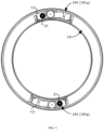
- one balancer 13 is located in one initial position 191.
- the two initial positions 191 are symmetrically arranged at 180 degrees. In this way, the balancers 11 can be kept balanced when the balancers 13 are not in motion.
- One balancer 13 is located at each of the initial position 191a and the initial position 191b.
- one, three, or more initial positions 191 may be provide, and the specific positions thereof may be set as required, which is not limited herein.
- the balance assembly 100 includes a first guide member 33 and a second guide member 35.
- the first guide member 33 is disposed on the balancer 13.
- the chamber 19 has a first inner wall 25, and a second inner wall 27 opposite to the first inner wall 25.
- the second guide member 35 is disposed on the second inner wall 27.
- the first guide member 33 is connected to the second guide member 35 to guide the movement of the balancer 13. In this way, the balancer 13 may be guided to stabilize the movement of the balancer 13.
- the balancer 13 may vibrate when moving in the chamber 1.
- the balancer 13 may deviate from the moving track when moving at a high speed, which may affect the movement of the balancer 13.
- the balancer 13 can move against the second inner wall 27, and thus the balancer 13 is guided to increase the stability of the balancer 13.
- the first guide member 33 includes a roller 45, and the roller 45 is connected to the second guide member 35. In this way, the frictional force between the balancer 13 and the second guide member 35 can be reduced when the balancer 13 is moving.
- the second guide member 35 is an annular guide rail arranged on the second inner wall 27.
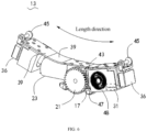
- the first guide member 33 includes two rollers 45 connected by a rotating shaft 46. The two rollers 45 can roll on the guide rail, and the two rollers 45 may clamp the guide rail.
- two first guide members 33 are arranged at both ends of the balancer 13 to further improve the smoothness of the movement of the balancer 13.
- the first guide member 33 and the second guide member 35 may be connected to each other by means of embedding, meshing and abutting, and may also play a guiding role. Other embodiments are not described in detail herein.
- the first guide member 33 includes a mounting member 36, a connecting member 37, and an elastic member 38.
- the mounting member 36 has a blind hole for accommodating the elastic member 38 defined therein.
- One end of the elastic member 38 is connected to the connecting member 37, and the other end of the elastic member 38 abuts against the bottom wall of the blind hole.
- the roller 45 is rotatably connected to the connecting member 37.
- the first guide member 33 is mounted on the balancer 13 through the mounting member 36. When the roller 45 is connected to the second guide member 35, the roller 45 may elastically compress the elastic member 38 through the connecting member 37 under the action of an excessively great force between the roller 45 and the second guide member 35.
- the elastic member 38 generates an elastic force facing away from the second guide member 35, which buffers the force between the roller 45 and the second guide member 35. Therefore, the friction between the balancer 13 and the second guide member 35 can be reduced to achieve the effect of vibration reduction.
- the elastic member 38 may ensure that the roller 45 is always connected to the second guide member 35.
- the first guide member 33 has two elastic members 38 disposed thereon and connected to the connecting member 37, and thus the mounting member 36 may bear a greater force.
- the balancer 13 further includes a bearing member 47.
- the bearing member 47 is fixedly connected to the driving member 23 and is configured to bear the centrifugal force of the circular motion of the balancer 13.
- the bearing member 47 has sliding wheels. The sliding wheels of the bearing member 47 move along the first inner wall 25 of the chamber 19 during the movement of the balancer 13. In this way, the bearing member 47 may abut against the first inner wall 25 to provide the support force of the first inner wall 25 to the balancer 13.
- the frictional force between the balancer 13 and the first inner wall 25 may be reduced at the same time.
- the balancer 13 includes a bracket 39.
- the balancer 13 may further include a power supply apparatus 48, and the power supply apparatus 48 can supply power to the balancer 13.
- the bracket 39 is designed as an arc-shaped structure along the circumferential direction of the chamber 19.
- the first detection member 17, the driving member 23, the controller 31, the first guide member 33, and the power supply apparatus 48 may all be arranged on the bracket 39.
- the balancer 13 may cooperate with the annular structure of the balancing ring 11 to move in the chamber 19 to avoid collision with the inner wall of the chamber 19.
- the bracket 39 may be made of thick stainless-steel plate, and thus the bracket 39 will not deform during the entire working process of the balancer 13.
- the power supply apparatus 48 may use a rechargeable battery to power the balancer 13.
- the balance assembly 100 includes a calibration member 41 and a second detection member 43.
- the balance assembly 100 is configured to cause a relative movement between the calibration member 41 and the second detection member 43 during the movement of the balancer 13, and cause the second detection member 43 to detect the calibration member 41 for eliminating a position error of the balancer 13.
- the controller 31 when the second detection member 43 passes through each calibration member 41, the information of the calibration member 41 detected by the second detection member 43 will be transmitted to the controller 31. Further, the controller 31 will set the position of the balancer 13 to a value of 0, that is, it is regarded as the origin to recalculate the moving distance of the balancer 13. In this way, the accumulated distance error caused by the long-term movement of the balancer 13, which may result in the inability to accurately determine the position of the balancer 13, can be avoided.
- the controller 31 starts to calculate the moving distance of the balancer 13 again and obtains the precise position information of the balancer 11 where the balancer 13 is located.
- a plurality of calibration members 41 is distributed and arranged at intervals on the inner wall of the chamber 19, such as the second inner wall 27.
- Each calibration member 41 includes a different number of calibration portions 42.
- the second detection member 43 may be one of an optical sensor, an ultrasonic sensor, and a Hall sensor.
- the second detection member 43 may trigger different pulse signals after passing through different numbers of calibration portions 42, and the number of pulses of the pulse signal is the same as the number of calibration portions 42.
- it can be determined based on the pulse signal output by the second detection member 43 that the balancer 13 is passing through a certain calibration member 41, and the specific position of the balancer 13 in the chamber 19 can be determined. In this way, the position of the balancer 13 may be tracked within the chamber 19.
- the inner wall of the chamber 19 has a calibration member 41 every 90 degrees, and the number of the calibration portions 42 is one, two, three and four, respectively.
- the calibration member 41 may be arranged on the second inner wall 27, and the calibration portion 42 may be a black and white stripe.
- the optical sensor may transmit an optical signal to the second inner wall 27 and receive the optical signal reflected on the second inner wall 27.
- the optical sensor will pass through the black and white stripe to change the intensity of the received optical signal, and thus pulse signals corresponding to the number of the calibration portions 42 can be output. Based on the pulse signals, the number of times of the balancer 13 passing through the calibration portion 42 may be determined, and the current position of the balancer 13 may be determined based on the position of the calibration member 41.
- the calibration portion 42 may also be a groove or a protrusion.
- the pulse signals corresponding to the number of the calibration portion 42 can also be obtained to finally determine the current position of the balancer 13.
- the mechanism of the ultrasonic sensor is similar to that of the optical sensor, and will not be repeated herein.
- the calibration portion 42 may be a protruding structure made of a metal material. It can be understood that, when the balancer 13 passes through the calibration member 41, the calibration member 41 will affect the direction of the magnetic field lines of the Hall sensor to change the density of the magnetic field lines passing through the Hall sensor, and the Hall sensor will output pulse signals corresponding to the number of calibration portions 42. Based on the pulse signals, the number of times of the calibration portion 42 passing through the sensor can be determined, and thus the current position of the balancer 13 can be determined based on the position of the calibration member 41.
- the number and position of the calibration members 41 as well as the number of the calibration portions 42 of the calibration member 41 may be adjusted based on specific conditions, and are not limited to the above embodiments.
- the first detection member 17 and the second detection member 43 are both disposed on the balancer 13, and the identification member 15 is disposed on the rotating member 21, and the calibration member 41 is disposed on an inner wall of the chamber 19. In this way, the mounting may be facilitated and the structure may be simplified.
- the rotating member 21 includes a gear 22, and the identification member 15 is a tooth of the gear 22.
- the calibration member 41 is disposed on the second inner wall 27, and the calibration member 41 is a protrusion.
- the first detection member 17 is mounted on the balancer 13 at a position facing the identification member 15, and the second detection member 43 is mounted on the balancer 13 at a position facing the second inner wall 27.
- the first detection member 17 and the second detection member 43 may be of the same type or different types.
- the first detection member 17 and the second detection member 43 may be both an optical sensor, an ultrasonic sensor, or a Hall sensor.
- the balancer 13 includes a controller 31.
- the controller 31 is connected to the first detection member 17 and the second detection member 43, and the controller 31 is configured to centrally process the detection results of the first detection member 17 and the second detection member 43.
- the controller 31 may be directly arranged on the balancer 13, without additionally arranging other controllers 31 on the balancing ring 11.
- a household appliance 200 is provided according to an embodiment of the present disclosure.
- the household appliance 200 includes a cavity 51 and the balance assembly 100 as described in any of the above embodiments.
- the cavity 51 has a rotation axis L.
- the balance assembly 100 is mounted in the cavity 51, and a central axis of a balancing ring 11 is parallel to or coincident with the rotation axis L of the cavity 51.
- the rotating member 21 may drive the balancer 13 to move within the chamber 19.
- the first detection member 17 may detect the number of times of the identification member 15 passing through the first detection member 17, and the number of times of the identification member 15 passing through the first detection member 17 may be used to determine the position of the balancer 13.
- the balancer 13 can reduce the vibration of the cavity 51.
- the household appliance 200 may be provided with a vibration sensor (not shown) and a main controller 50.
- the vibration sensor may be configured to detect the vibration information of the cavity 51 or the vibration information of other components connected to the cavity 51.
- the main controller 50 may control, based on the vibration information, the movement of the balancer 13 to adjust the specific position of the balancer 13 in the cavity 19, to counteract or reduce the vibration of the cavity 51.
- the main controller 50 may be in communication with the controller 31 of the balance assembly 100 in a wired or wireless manner, to transmit a current state signal and movement signal of the balancer 13 and the like.
- the current state signal of the balancer 13 includes a current position of the balancer 13, whether the balancer 13 is in a moving state, a communication connection state, and the like.
- the main controller 50 may transmit the movement signal to the controller 31, and based on the movement signal, the controller 31 controls the movement of the balancer 13.
- the controller 31 may transmit the current state signal of the balancer 13 to the main controller 50, and the current state signal of the balancer 13 is received and analyzed by the main controller 50 to obtain the current position, movement state and communication connection state, and the like of the balancer 13.
- the household appliance 200 may be a laundry appliance such as a washing machine or a dryer, or other household appliances 200 having a rotatable cavity 51.
- the household appliance 200 is a washing machine for washing clothes.
- the cavity 51 is an inner drum, and the inner drum is rotatably disposed in the outer drum 53. Clothes are placed in the inner drum.
- the inner drum rotates at a high speed, and the clothes in the inner drum may be unevenly distributed, which may result in an eccentric vibration.
- the washing machine may vibrate strenuously.
- the vibration of the inner drum may be transmitted to the outer drum 53, by detecting the vibration information of the outer drum 53, it may be determined whether the inner drum is in a state of eccentric vibration.
- the balancing ring 11 is connected and fixed to the inner drum can rotate together with the inner drum. Therefore, the movement of the balancer 13 in the chamber 19 may be controlled based on the vibration information to offset or reduce the eccentric mass during the rotation of the inner drum.
- the outer drum 53 may be connected to a mounting plate 55 through a vibration damping structure 54, and the mounting plate 55 may be fixed on a housing bottom plate of the household appliance 200.
- the vibration damping structure 54 may adopt vibration damping methods such as spring and hydraulic pressure.
Landscapes
- Engineering & Computer Science (AREA)
- Textile Engineering (AREA)
- Rolling Contact Bearings (AREA)
- Toys (AREA)
Claims (8)
- Auswuchtungsbaugruppe (100), angewandt in einem Haushaltsgerät (200), wobei die Auswuchtungsbaugruppe (100) Folgendes umfasst:einen Auswuchtungsring (11) mit einer darin definierten Kammer (19),eine Auswuchtungsvorrichtung (13), die beweglich in der Kammer (19) angeordnet ist und ein rotierendes Element (21) und ein Antriebselement (23) umfasst, wobei das Antriebselement (23) mit dem rotierenden Element (21) verbunden und dafür gestaltet ist, das rotierende Element (21) zum Rotieren anzutreiben, um eine Bewegung der Auswuchtungsvorrichtung (13) in der Kammer (19) anzutreiben,ein Identifikationselement (15) undein erstes Erkennungselement (17),wobei die Auswuchtungsbaugruppe (100) dafür gestaltet ist, während der Bewegung der Auswuchtungsvorrichtung (13) eine relative Bewegung zwischen dem Identifikationselement (15) und dem ersten Erkennungselement (17) zu bewirken, wobei das erste Erkennungselement (17) dafür gestaltet ist, eine Anzahl der Durchläufe des Identifikationselements (15) durch das erste Erkennungselement (17) zu erkennen, wobei die Anzahl der Durchläufe des Identifikationselements (15) durch das erste Erkennungselement (17) in Beziehung zu einer Position der Auswuchtungsvorrichtung (13) steht,dadurch gekennzeichnet, dass das Identifikationselement (15) an dem rotierenden Element (21) angeordnet ist, und wobei das rotierende Element (21) ein Zahnrad (22) umfasst, wobei die Kammer (19) eine erste Innenwand (25) mit einem daran angeordneten Zahnkranzabschnitt (29) umfasst, wobei das Zahnrad (22) mit dem Zahnkranzabschnitt (29) in Eingriff steht und wobei das Identifikationselement (15) ein Zahn des Zahnrades (22) oder ein Zahn des Zahnkranzabschnitts (29) ist.
- Auswuchtungsbaugruppe (100) nach Anspruch 1, wobei das erste Erkennungselement (17) mindestens eines von einem optischen Sensor, einem Hall-Sensor oder einem Ultraschallsensor umfasst.
- Auswuchtungsbaugruppe (100) nach Anspruch 1, ferner umfassend:eine Steuerung (31), die elektrisch mit dem ersten Erkennungselement (17) verbunden ist,wobei die Kammer (19) eine Anfangsposition (191) aufweist und wobei die Steuerung (31) dafür gestaltet ist, die Position der Auswuchtungsvorrichtung (13) basierend auf der Anfangsposition (191) und der Anzahl der Durchläufe des Identifikationselements (15) durch das erste Erkennungselement (17) zu bestimmen.
- Auswuchtungsbaugruppe (100) nach Anspruch 1, ferner umfassend:ein erstes Führungselement (33), das an der Auswuchtungsvorrichtung (13) angeordnet ist, undein zweites Führungselement (35),wobei die Kammer (19) eine erste Innenwand (25) und eine zweite Innenwand (27) gegenüber der ersten Innenwand (25) umfasst, wobei das zweite Führungselement (35) an der zweiten Innenwand (27) angeordnet ist und wobei das erste Führungselement (33) mit dem zweiten Führungselement (35) verbunden ist, um die Bewegung der Auswuchtungsvorrichtung (13) zu führen.
- Auswuchtungsbaugruppe (100) nach Anspruch 4, wobei das erste Führungselement (33) eine Rolle (45) umfasst, die mit dem zweiten Führungselement (35) verbunden ist.
- Auswuchtungsbaugruppe (100) nach Anspruch 1, ferner umfassend:ein Kalibrierungselement (41) undein zweites Erkennungselement (43),wobei die Auswuchtungsbaugruppe (100) dafür gestaltet ist, während der Bewegung der Auswuchtungsvorrichtung (13) eine relative Bewegung zwischen dem Kalibrierungselement (41) und dem zweiten Erkennungselement (43) zu bewirken und zu bewirken, dass das zweite Erkennungselement (43) das Kalibrierungselement (41) erkennt, um einen Positionsfehler der Auswuchtungsvorrichtung (13) zu beheben.
- Auswuchtungsbaugruppe (100) nach Anspruch 6, wobei sowohl das erste Erkennungselement (17) als auch das zweite Erkennungselement (43) an der Auswuchtungsvorrichtung (13) angeordnet sind und wobei das Kalibrierungselement (41) an einer Innenwand der Kammer (19) angeordnet ist.
- Haushaltsgerät (200), umfassend:einen Hohlraum (51) mit einer Rotationsachse unddie Auswuchtungsbaugruppe (100) nach einem der Ansprüche 1 bis 7, wobei die Auswuchtungsbaugruppe (100) in dem Hohlraum (51) montiert ist, wobei eine Mittelachse des Auswuchtungsrings (11) parallel zur Rotationsachse des Hohlraums (51) liegt oder mit dieser zusammenfällt.
Applications Claiming Priority (3)
| Application Number | Priority Date | Filing Date | Title |
|---|---|---|---|
| CN201911415572.5A CN113123076B (zh) | 2019-12-31 | 2019-12-31 | 平衡组件和家用电器 |
| CN201922500716.9U CN211395010U (zh) | 2019-12-31 | 2019-12-31 | 平衡组件和家用电器 |
| PCT/CN2020/136236 WO2021135912A1 (zh) | 2019-12-31 | 2020-12-14 | 平衡组件和家用电器 |
Publications (3)
| Publication Number | Publication Date |
|---|---|
| EP4067554A1 EP4067554A1 (de) | 2022-10-05 |
| EP4067554A4 EP4067554A4 (de) | 2023-01-25 |
| EP4067554B1 true EP4067554B1 (de) | 2025-06-18 |
Family
ID=76686487
Family Applications (1)
| Application Number | Title | Priority Date | Filing Date |
|---|---|---|---|
| EP20910335.7A Active EP4067554B1 (de) | 2019-12-31 | 2020-12-14 | Balanceanordnung und haushaltsgerät |
Country Status (3)
| Country | Link |
|---|---|
| US (1) | US12312729B2 (de) |
| EP (1) | EP4067554B1 (de) |
| WO (1) | WO2021135912A1 (de) |
Family Cites Families (17)
| Publication number | Priority date | Publication date | Assignee | Title |
|---|---|---|---|---|
| US4117742A (en) * | 1977-07-29 | 1978-10-03 | Stein Philip C | Permanent automatic rotor balancer for shafts operating above critical speed |
| SE504512C2 (sv) * | 1994-07-26 | 1997-02-24 | Electrolux Ab | Anordning för balansering av en kring en axel roterbar kropp |
| PT1088126E (pt) * | 1998-04-14 | 2005-04-29 | Tulga Simsek | Uma maquina e um metodo para o equilibrio de uma tal maquina |
| KR101612701B1 (ko) | 2009-07-27 | 2016-04-15 | 엘지전자 주식회사 | 세탁장치 및 그 제어 방법 |
| CN102101251B (zh) | 2009-12-17 | 2013-01-23 | 武汉重型机床集团有限公司 | 位置检测控制装置 |
| WO2011115384A2 (ko) * | 2010-03-15 | 2011-09-22 | 엘지전자 주식회사 | 세탁장치 및 그 제어방법 |
| KR101806836B1 (ko) * | 2011-05-04 | 2017-12-11 | 삼성전자주식회사 | 세탁기 및 그 제어방법 |
| US9441697B2 (en) * | 2012-06-07 | 2016-09-13 | Samsung Electronics Co., Ltd. | Balancing module and washing machine having the same |
| WO2013183929A1 (en) * | 2012-06-07 | 2013-12-12 | Samsung Electronics Co., Ltd. | Balancer, balancer housing, washing machine having the same and control method thereof |
| KR101944370B1 (ko) | 2012-10-12 | 2019-02-07 | 삼성전자주식회사 | 밸런서를 갖는 세탁기 및 그 제어 방법 |
| WO2015190659A1 (ko) * | 2014-06-09 | 2015-12-17 | 엘지전자 주식회사 | 세탁장치 |
| CN105624972B (zh) * | 2016-03-28 | 2017-11-07 | 惠而浦(中国)股份有限公司 | 基于3d位移传感器判断偏心的滚筒洗衣机脱水控制方法 |
| KR20170135251A (ko) * | 2016-05-31 | 2017-12-08 | 엘지전자 주식회사 | 세탁장치 및 그 제어방법 |
| KR102327840B1 (ko) | 2017-04-10 | 2021-11-17 | 엘지전자 주식회사 | 세탁기 및 그 제어방법 |
| CN211395025U (zh) * | 2019-12-31 | 2020-09-01 | 广东美的白色家电技术创新中心有限公司 | 平衡组件和家用电器 |
| CN211395022U (zh) * | 2019-12-31 | 2020-09-01 | 广东美的白色家电技术创新中心有限公司 | 平衡组件及家用电器 |
| CN211395010U (zh) * | 2019-12-31 | 2020-09-01 | 广东美的白色家电技术创新中心有限公司 | 平衡组件和家用电器 |
-
2020
- 2020-12-14 EP EP20910335.7A patent/EP4067554B1/de active Active
- 2020-12-14 US US17/789,213 patent/US12312729B2/en active Active
- 2020-12-14 WO PCT/CN2020/136236 patent/WO2021135912A1/zh not_active Ceased
Also Published As
| Publication number | Publication date |
|---|---|
| EP4067554A4 (de) | 2023-01-25 |
| EP4067554A1 (de) | 2022-10-05 |
| WO2021135912A1 (zh) | 2021-07-08 |
| US12312729B2 (en) | 2025-05-27 |
| US20220389635A1 (en) | 2022-12-08 |
Similar Documents
| Publication | Publication Date | Title |
|---|---|---|
| JP3625791B2 (ja) | ドラム式洗濯機 | |
| CN212388220U (zh) | 平衡组件及家用电器 | |
| US6374444B2 (en) | Method for determining the loading weight of a laundry drum and a laundry-processing machine for carrying out the method | |
| US6029299A (en) | Method for detecting cloth amount in drum washing machine | |
| CN212388219U (zh) | 平衡组件及家用电器 | |
| US8627525B2 (en) | Method for the control of a spinning cycle of a washing machine and a washing machine suitable for performing said method | |
| KR20120124769A (ko) | 세탁기 및 그 제어방법 | |
| EP4067554B1 (de) | Balanceanordnung und haushaltsgerät | |
| CN113123076B (zh) | 平衡组件和家用电器 | |
| CN211395010U (zh) | 平衡组件和家用电器 | |
| EP4067553B1 (de) | Haushaltsgerät mit unwuchtausgleichsvorrichtung | |
| CN212388221U (zh) | 平衡组件及家用电器 | |
| JP4513033B2 (ja) | 光センサ装置を持つ測定装置及び測定装置による測定方法 | |
| KR102221293B1 (ko) | 세탁장치 | |
| WO2022021729A1 (zh) | 平衡组件及家用电器 | |
| KR102145740B1 (ko) | 세탁장치 | |
| EP3255386A1 (de) | Absoluter codierer von rohrmotor | |
| CN113123083B (zh) | 平衡组件及家用电器 | |
| CN211395023U (zh) | 平衡组件和家用电器 | |
| CN114059293A (zh) | 平衡组件及家用电器 | |
| KR101729549B1 (ko) | 세탁장치 및 그 제어방법 | |
| CN113123081B (zh) | 平衡组件和家用电器 | |
| WO2020251505A1 (en) | A washing machine comprising a belt-pulley and the operation method thereof | |
| CN114059296B (zh) | 平衡组件及家用电器 | |
| CN211395031U (zh) | 平衡组件、衣物处理电器和家用电器 |
Legal Events
| Date | Code | Title | Description |
|---|---|---|---|
| STAA | Information on the status of an ep patent application or granted ep patent |
Free format text: STATUS: THE INTERNATIONAL PUBLICATION HAS BEEN MADE |
|
| PUAI | Public reference made under article 153(3) epc to a published international application that has entered the european phase |
Free format text: ORIGINAL CODE: 0009012 |
|
| STAA | Information on the status of an ep patent application or granted ep patent |
Free format text: STATUS: REQUEST FOR EXAMINATION WAS MADE |
|
| 17P | Request for examination filed |
Effective date: 20220629 |
|
| AK | Designated contracting states |
Kind code of ref document: A1 Designated state(s): AL AT BE BG CH CY CZ DE DK EE ES FI FR GB GR HR HU IE IS IT LI LT LU LV MC MK MT NL NO PL PT RO RS SE SI SK SM TR |
|
| A4 | Supplementary search report drawn up and despatched |
Effective date: 20230104 |
|
| RIC1 | Information provided on ipc code assigned before grant |
Ipc: D06F 37/22 20060101AFI20221222BHEP |
|
| DAV | Request for validation of the european patent (deleted) | ||
| DAX | Request for extension of the european patent (deleted) | ||
| GRAP | Despatch of communication of intention to grant a patent |
Free format text: ORIGINAL CODE: EPIDOSNIGR1 |
|
| STAA | Information on the status of an ep patent application or granted ep patent |
Free format text: STATUS: GRANT OF PATENT IS INTENDED |
|
| GRAS | Grant fee paid |
Free format text: ORIGINAL CODE: EPIDOSNIGR3 |
|
| INTG | Intention to grant announced |
Effective date: 20250415 |
|
| GRAA | (expected) grant |
Free format text: ORIGINAL CODE: 0009210 |
|
| STAA | Information on the status of an ep patent application or granted ep patent |
Free format text: STATUS: THE PATENT HAS BEEN GRANTED |
|
| AK | Designated contracting states |
Kind code of ref document: B1 Designated state(s): AL AT BE BG CH CY CZ DE DK EE ES FI FR GB GR HR HU IE IS IT LI LT LU LV MC MK MT NL NO PL PT RO RS SE SI SK SM TR |
|
| REG | Reference to a national code |
Ref country code: GB Ref legal event code: FG4D |
|
| REG | Reference to a national code |
Ref country code: CH Ref legal event code: EP |
|
| REG | Reference to a national code |
Ref country code: DE Ref legal event code: R096 Ref document number: 602020053102 Country of ref document: DE |
|
| REG | Reference to a national code |
Ref country code: CH Ref legal event code: EP |
|
| REG | Reference to a national code |
Ref country code: IE Ref legal event code: FG4D |
|
| PG25 | Lapsed in a contracting state [announced via postgrant information from national office to epo] |
Ref country code: FI Free format text: LAPSE BECAUSE OF FAILURE TO SUBMIT A TRANSLATION OF THE DESCRIPTION OR TO PAY THE FEE WITHIN THE PRESCRIBED TIME-LIMIT Effective date: 20250618 |
|
| REG | Reference to a national code |
Ref country code: LT Ref legal event code: MG9D |
|
| PG25 | Lapsed in a contracting state [announced via postgrant information from national office to epo] |
Ref country code: NO Free format text: LAPSE BECAUSE OF FAILURE TO SUBMIT A TRANSLATION OF THE DESCRIPTION OR TO PAY THE FEE WITHIN THE PRESCRIBED TIME-LIMIT Effective date: 20250918 Ref country code: GR Free format text: LAPSE BECAUSE OF FAILURE TO SUBMIT A TRANSLATION OF THE DESCRIPTION OR TO PAY THE FEE WITHIN THE PRESCRIBED TIME-LIMIT Effective date: 20250919 |
|
| PG25 | Lapsed in a contracting state [announced via postgrant information from national office to epo] |
Ref country code: BG Free format text: LAPSE BECAUSE OF FAILURE TO SUBMIT A TRANSLATION OF THE DESCRIPTION OR TO PAY THE FEE WITHIN THE PRESCRIBED TIME-LIMIT Effective date: 20250618 |
|
| PG25 | Lapsed in a contracting state [announced via postgrant information from national office to epo] |
Ref country code: HR Free format text: LAPSE BECAUSE OF FAILURE TO SUBMIT A TRANSLATION OF THE DESCRIPTION OR TO PAY THE FEE WITHIN THE PRESCRIBED TIME-LIMIT Effective date: 20250618 |
|
| PG25 | Lapsed in a contracting state [announced via postgrant information from national office to epo] |
Ref country code: RS Free format text: LAPSE BECAUSE OF FAILURE TO SUBMIT A TRANSLATION OF THE DESCRIPTION OR TO PAY THE FEE WITHIN THE PRESCRIBED TIME-LIMIT Effective date: 20250918 |
|
| REG | Reference to a national code |
Ref country code: NL Ref legal event code: MP Effective date: 20250618 |
|
| PG25 | Lapsed in a contracting state [announced via postgrant information from national office to epo] |
Ref country code: LV Free format text: LAPSE BECAUSE OF FAILURE TO SUBMIT A TRANSLATION OF THE DESCRIPTION OR TO PAY THE FEE WITHIN THE PRESCRIBED TIME-LIMIT Effective date: 20250618 |
|
| PG25 | Lapsed in a contracting state [announced via postgrant information from national office to epo] |
Ref country code: NL Free format text: LAPSE BECAUSE OF FAILURE TO SUBMIT A TRANSLATION OF THE DESCRIPTION OR TO PAY THE FEE WITHIN THE PRESCRIBED TIME-LIMIT Effective date: 20250618 |
|
| PG25 | Lapsed in a contracting state [announced via postgrant information from national office to epo] |
Ref country code: PT Free format text: LAPSE BECAUSE OF FAILURE TO SUBMIT A TRANSLATION OF THE DESCRIPTION OR TO PAY THE FEE WITHIN THE PRESCRIBED TIME-LIMIT Effective date: 20251020 |
|
| REG | Reference to a national code |
Ref country code: AT Ref legal event code: MK05 Ref document number: 1804256 Country of ref document: AT Kind code of ref document: T Effective date: 20250618 |
|
| PG25 | Lapsed in a contracting state [announced via postgrant information from national office to epo] |
Ref country code: IS Free format text: LAPSE BECAUSE OF FAILURE TO SUBMIT A TRANSLATION OF THE DESCRIPTION OR TO PAY THE FEE WITHIN THE PRESCRIBED TIME-LIMIT Effective date: 20251018 |
|
| PGFP | Annual fee paid to national office [announced via postgrant information from national office to epo] |
Ref country code: DE Payment date: 20251212 Year of fee payment: 6 |
|
| PGFP | Annual fee paid to national office [announced via postgrant information from national office to epo] |
Ref country code: GB Payment date: 20251211 Year of fee payment: 6 |
|
| PG25 | Lapsed in a contracting state [announced via postgrant information from national office to epo] |
Ref country code: AT Free format text: LAPSE BECAUSE OF FAILURE TO SUBMIT A TRANSLATION OF THE DESCRIPTION OR TO PAY THE FEE WITHIN THE PRESCRIBED TIME-LIMIT Effective date: 20250618 Ref country code: SM Free format text: LAPSE BECAUSE OF FAILURE TO SUBMIT A TRANSLATION OF THE DESCRIPTION OR TO PAY THE FEE WITHIN THE PRESCRIBED TIME-LIMIT Effective date: 20250618 |
|
| PGFP | Annual fee paid to national office [announced via postgrant information from national office to epo] |
Ref country code: FR Payment date: 20251212 Year of fee payment: 6 |
|
| PG25 | Lapsed in a contracting state [announced via postgrant information from national office to epo] |
Ref country code: CZ Free format text: LAPSE BECAUSE OF FAILURE TO SUBMIT A TRANSLATION OF THE DESCRIPTION OR TO PAY THE FEE WITHIN THE PRESCRIBED TIME-LIMIT Effective date: 20250618 |
|
| PG25 | Lapsed in a contracting state [announced via postgrant information from national office to epo] |
Ref country code: PL Free format text: LAPSE BECAUSE OF FAILURE TO SUBMIT A TRANSLATION OF THE DESCRIPTION OR TO PAY THE FEE WITHIN THE PRESCRIBED TIME-LIMIT Effective date: 20250618 |
|
| PG25 | Lapsed in a contracting state [announced via postgrant information from national office to epo] |
Ref country code: EE Free format text: LAPSE BECAUSE OF FAILURE TO SUBMIT A TRANSLATION OF THE DESCRIPTION OR TO PAY THE FEE WITHIN THE PRESCRIBED TIME-LIMIT Effective date: 20250618 |
|
| PG25 | Lapsed in a contracting state [announced via postgrant information from national office to epo] |
Ref country code: SK Free format text: LAPSE BECAUSE OF FAILURE TO SUBMIT A TRANSLATION OF THE DESCRIPTION OR TO PAY THE FEE WITHIN THE PRESCRIBED TIME-LIMIT Effective date: 20250618 |
|
| PG25 | Lapsed in a contracting state [announced via postgrant information from national office to epo] |
Ref country code: ES Free format text: LAPSE BECAUSE OF FAILURE TO SUBMIT A TRANSLATION OF THE DESCRIPTION OR TO PAY THE FEE WITHIN THE PRESCRIBED TIME-LIMIT Effective date: 20250618 |
|
| PG25 | Lapsed in a contracting state [announced via postgrant information from national office to epo] |
Ref country code: RO Free format text: LAPSE BECAUSE OF FAILURE TO SUBMIT A TRANSLATION OF THE DESCRIPTION OR TO PAY THE FEE WITHIN THE PRESCRIBED TIME-LIMIT Effective date: 20250618 |
|
| PG25 | Lapsed in a contracting state [announced via postgrant information from national office to epo] |
Ref country code: DK Free format text: LAPSE BECAUSE OF FAILURE TO SUBMIT A TRANSLATION OF THE DESCRIPTION OR TO PAY THE FEE WITHIN THE PRESCRIBED TIME-LIMIT Effective date: 20250618 |
|
| PG25 | Lapsed in a contracting state [announced via postgrant information from national office to epo] |
Ref country code: IT Free format text: LAPSE BECAUSE OF FAILURE TO SUBMIT A TRANSLATION OF THE DESCRIPTION OR TO PAY THE FEE WITHIN THE PRESCRIBED TIME-LIMIT Effective date: 20250618 |
|
| PLBE | No opposition filed within time limit |
Free format text: ORIGINAL CODE: 0009261 |
|
| STAA | Information on the status of an ep patent application or granted ep patent |
Free format text: STATUS: NO OPPOSITION FILED WITHIN TIME LIMIT |
|
| REG | Reference to a national code |
Ref country code: CH Ref legal event code: L10 Free format text: ST27 STATUS EVENT CODE: U-0-0-L10-L00 (AS PROVIDED BY THE NATIONAL OFFICE) Effective date: 20260430 |