EP4067560B1 - Ensemble filtrant annulaire et dispositif de séchage de vêtements - Google Patents
Ensemble filtrant annulaire et dispositif de séchage de vêtements Download PDFInfo
- Publication number
- EP4067560B1 EP4067560B1 EP20894605.3A EP20894605A EP4067560B1 EP 4067560 B1 EP4067560 B1 EP 4067560B1 EP 20894605 A EP20894605 A EP 20894605A EP 4067560 B1 EP4067560 B1 EP 4067560B1
- Authority
- EP
- European Patent Office
- Prior art keywords
- arc
- annular filter
- annular
- filter screens
- shaped filter
- Prior art date
- Legal status (The legal status is an assumption and is not a legal conclusion. Google has not performed a legal analysis and makes no representation as to the accuracy of the status listed.)
- Active
Links
Images


Classifications
-
- D—TEXTILES; PAPER
- D06—TREATMENT OF TEXTILES OR THE LIKE; LAUNDERING; FLEXIBLE MATERIALS NOT OTHERWISE PROVIDED FOR
- D06F—LAUNDERING, DRYING, IRONING, PRESSING OR FOLDING TEXTILE ARTICLES
- D06F58/00—Domestic laundry dryers
- D06F58/20—General details of domestic laundry dryers
- D06F58/22—Lint collecting arrangements
-
- B—PERFORMING OPERATIONS; TRANSPORTING
- B01—PHYSICAL OR CHEMICAL PROCESSES OR APPARATUS IN GENERAL
- B01D—SEPARATION
- B01D46/00—Filters or filtering processes specially modified for separating dispersed particles from gases or vapours
- B01D46/24—Particle separators, e.g. dust precipitators, using rigid hollow filter bodies
- B01D46/2403—Particle separators, e.g. dust precipitators, using rigid hollow filter bodies characterised by the physical shape or structure of the filtering element
-
- D—TEXTILES; PAPER
- D06—TREATMENT OF TEXTILES OR THE LIKE; LAUNDERING; FLEXIBLE MATERIALS NOT OTHERWISE PROVIDED FOR
- D06F—LAUNDERING, DRYING, IRONING, PRESSING OR FOLDING TEXTILE ARTICLES
- D06F58/00—Domestic laundry dryers
- D06F58/02—Domestic laundry dryers having dryer drums rotating about a horizontal axis
- D06F58/04—Details
-
- B—PERFORMING OPERATIONS; TRANSPORTING
- B01—PHYSICAL OR CHEMICAL PROCESSES OR APPARATUS IN GENERAL
- B01D—SEPARATION
- B01D46/00—Filters or filtering processes specially modified for separating dispersed particles from gases or vapours
- B01D46/10—Particle separators, e.g. dust precipitators, using filter plates, sheets or pads having plane surfaces
- B01D46/103—Curved filtering elements
Definitions
- the present invention belongs to the technical field of filtering, and specifically provides an annular filter assembly and a clothing drying apparatus.
- Filtering is a process of refining and purifying a fluid by a special device.
- the special device is a filter device, and the fluid may be liquids such as water, or gases such as air, or solids such as quicksand.
- the filter device is widely used in fields such as household appliance, agriculture, experiment, industrial production, etc.
- the common clothing drying apparatus includes a drum clothing dryer and a clothing care machine, etc.
- a filtering mode of the traditional drum clothing dryer is to provide a fixed filter screen in an air duct for filtering. Due to the limitation of the closed structure of the air duct, it is very inconvenient to clean the filter screen, resulting in a poor user experience in use.
- the prior art has developed a filter device with exchangeable filter sections.
- PCT patent application WO1994019088A1 discloses a device for filtering liquids.
- the device has an annular disc with at least one perforated side wall, and a plurality of separate section of a filter medium are applied onto frames and each said section covers a part of the perforated side wall.
- European patent application EP2745909A1 discloses a stream strainer, wherein it has a skeleton-like tube body and at least two shell-type individual elements which are exchangeable. However, the exchangeable filter sections are easily fell off during application.
- the present disclosure provides an annular filter assembly as set out in the appended set of claims.
- the plurality of arc-shaped filter screens and the annular filter bracket are detachably connected, so that each of the arc-shaped filter screens can be detached from the annular filter bracket separately, which facilitates cleaning, replacement and maintenance of the filter screens.
- the structure of the plurality of arc-shaped filter screens if one of the arc-shaped filter screens is damaged, only this damaged arc-shaped filter screen has to be repaired or replaced, with no need to detach all the filter screens, thereby reducing the maintenance cost for the user and improves the user experience in use.
- the arc-shaped filter screens are accommodated by the accommodating groove, so that a certain positioning effect can be realized on the arc-shaped filter screens, the arc-shaped filter screens can be prevented from displacing, and the stability of the structure can be further improved. Further, the inner surfaces of the arc-shaped filter screens are set flush with the inner surface of the annular filter bracket. Through such an arrangement, the arc-shaped filter screens are prevented from protruding beyond a groove top of accommodating groove, so that at the same time of improving structural aesthetics, it is ensured that the arc-shaped filter screens will not be easily scratched by foreign objects to move out of the accommodating groove.
- the plurality of arc-shaped filter screens are all connected with the annular filter bracket by snap-fit.
- the rib structures can ensure the snap-fit effect on the arc-shaped filter screens, and the stability of the structure is improved.
- first ribs and the second ribs may snap-fit the arc-shaped filter screens on the annular filter bracket from both sides of the arc-shaped filter screens, which can further improve the snap-fit effect on the arc-shaped filter screens, and further improve structural stability.
- arc lengths of all the arc-shaped filter screens may be equal.
- the accommodating groove may be an annular accommodating groove, that is, all the arc-shaped filter screens can be accommodated by the annular accommodating groove, so that the structure of the product is simplified while positioning the arc-shaped filter screens.
- the present disclosure also provides a clothing drying apparatus, which includes a cabinet assembly and a drying drum;
- the cabinet assembly includes a front panel and a front support mechanism, the front support mechanism is arranged on the front panel, and the front panel is provided with a clothing throw-in port in communication with an interior of the drying drum;
- the clothing drying apparatus further includes the above annular filter assembly, the annular filter bracket is arranged between the front support mechanism and the drying drum, and the annular filter bracket is arranged to be capable of rotating together with the drying drum.
- the annular filter assembly can fully filter out the lint in the drying drum, and the area of the annular filter assembly is made large enough; moreover, the filtering is performed in a rotary manner, so that there is no dead end in the filtering, the filtering effect is improved, and the user experience in use is improved.
- the clothing drying apparatus further may include a lint cleaning member and a lint collecting member, which are both arranged on the front support mechanism; in the process of driving the annular filter bracket to rotate by the drying drum, the lint cleaning member can clean up the lint on the plurality of arc-shaped filter screens, and the lint collecting member can collect the cleaned up lint.
- the lint adhered to the annular filter assembly can be removed into the lint collecting member under the action of the lint cleaning member to complete the operation of collecting the lint.
- the user does not need to clean the annular filter assembly frequently, which greatly improves the user experience in use.
- the lint cleaning member and the lint collecting member are both arranged on the front support mechanism, so they do not occupy other space and will not affect the normal use by the user.
- 1 annular filter bracket; 11: first rib; 12: second rib; 2: arc-shaped filter screen; 3: front panel; 4: front support mechanism; 5: drying drum; 6: lint cleaning member; 7: lint collecting member.
- connection may be a fixed connection, or may also be a detachable connection, or an integral connection; it may be a mechanical connection, or an electrical connection; it may be a direct connection, or an indirect connection implemented through an intermediate medium, or it may be internal communication between two elements.
- connection may be a fixed connection, or may also be a detachable connection, or an integral connection; it may be a mechanical connection, or an electrical connection; it may be a direct connection, or an indirect connection implemented through an intermediate medium, or it may be internal communication between two elements.
- the present disclosure provides an annular filter assembly and a clothing drying apparatus, aiming at facilitating detachment, maintenance and replacement of the filter device and improving the user experience in use.
- annular filter assembly of the present disclosure can be applied to various fields such as production and processing, washing and caring, dust removal and purification, and ambient temperature regulation.
- the technical solution of the present disclosure will be described in greater detail in connection with the structure of the annular filter assembly itself and a clothing drying apparatus using the annular filter assembly of the present disclosure in the field of washing and caring, respectively.
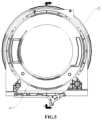
- the annular filter assembly of the present disclosure includes an annular filter bracket 1 and a plurality of arc-shaped filter screens 2.
- the plurality of arc-shaped filter screens 2 are all detachably connected with the annular filter bracket 1, and the plurality of arc-shaped filter screens 2 are arranged in sequence in a circumferential direction of the annular filter bracket 1.
- the arc-shaped filter screens 2 can be detachably connected with the annular filter bracket 1 by threads, snap-fit, bonding and/or magnetic adsorption, and all the arc-shaped filter screens 2 can be connected with the annular filter bracket 1 in the same way or in different ways.
- each two adjacent arc-shaped filter screens 2 may be arranged against each other, or they may be arranged slightly spaced apart.
- arc lengths of all the arc-shaped filter screens 2 may be equal to each other, or not equal to each other, and those skilled in the art can flexibly set the arc lengths of the arc-shaped filter screens 2 in practical applications.
- the plurality of arc-shaped filter screens 2 are all connected with the annular filter bracket 1 by snap-fit.
- the arc-shaped filter screens 2 can be snap-fit with the annular filter bracket 1 through a claw structure, or the arc-shaped filter screens 2 can be snap-fit with the annular filter bracket 1 through a rib structure, or the arc-shaped filter screens 2 can be snap-fit with the annular filter bracket 1 through a clasp structure, or the arc-shaped filter screens 2 can be snap-fit with the annular filter bracket 1 through an elastic clip structure, or the arc-shaped filter screens 2 can be snap-fit with the annular filter bracket 1 through a combination of the above means.
- the annular filter bracket 1 is provided with rib structures, and the arc-shaped filter screens 2 are snap-fit on the annular filter bracket 1 through the rib structures.
- the rib structures can snap-fit the arc-shaped filter screens 2 from one side of the arc-shaped filter screens 2, and can also snap-fit the arc-shaped filter screens 2 from both sides of the arc-shaped filter screens 2.
- Those skilled in the art can flexibly set the specific means of snap-fitting the arc-shaped filter screens 2 by the rib structures in practical applications.
- the adjustment and change to the specific snap-fit means of the arc-shaped filter screens 2 do not constitute limitations to the present disclosure, and they should all be defined within the scope of protection of the present disclosure.
- the rib structures include first ribs 11 and second ribs 12 that are formed on the annular filter bracket 1 and are located on both sides of the arc-shaped filter screens 2 respectively.
- the first ribs 11 and the second ribs 12 together snap-fit the arc-shaped filter screens 2 on the annular filter bracket 1.
- Each arc-shaped filter screen 2 corresponds to one first rib 11 or a plurality of first ribs 11.
- each arc-shaped filter screen 2 corresponds to one second rib 12 or a plurality of second ribs 12.
- the first rib 11 can also snap-fit two adjacent arc-shaped filter screens 2 at the same time.
- the second rib 12 can also snap-fit two adjacent arc-shaped filter screens 2 at the same time.
- Those skilled in the art can flexibly set the number and snap-fit means of the first ribs 11 and the second ribs 12 in practical applications.
- the adjustment and change to the number and snap-fit means of the first ribs 11 and the second ribs 12 do not constitute limitations to the present disclosure, and they should all be defined within the scope of protection of the present disclosure.
- an accommodating groove is formed on the annular filter bracket 1, and the arc-shaped filter screens 2 are arranged in the accommodating groove.
- the accommodating groove is an annular accommodating groove, and the plurality of arc-shaped filter screens 2 are arranged in sequence in the annular accommodating groove in the circumferential direction of the annular filter bracket 1.
- the accommodating groove may also include a plurality of arc-shaped accommodating grooves, and the arc-shaped accommodating grooves correspond to the arc-shaped filter screens 2 in a one-to-one correspondence.
- the corresponding arc-shaped filter screen 2 is accommodated by the arc-shaped accommodating groove.
- one arc-shaped accommodating groove corresponds to two arc-shaped filter screens 2.
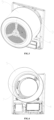
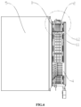
- inner surfaces of the arc-shaped filter screens 2 are set flush with an inner surface of the annular filter bracket 1. As shown in FIGS. 1 and 2 , bottom surfaces of the arc-shaped filter screens 2 abut against a groove bottom of the accommodating groove, and top surfaces of the arc-shaped filter screens 2 are flush with a groove top edge of the accommodating groove.
- the clothing drying apparatus can be a drum clothing dryer, a cabinet clothing dryer or a drawer clothing dryer, etc. In the following, only the clothing drying apparatus which is a front-open drum clothing dryer will be described exemplarily.
- the drum clothing dryer includes a cabinet assembly and a drying drum 5;
- the cabinet assembly includes a front panel 3 and a front support mechanism 4, the front support mechanism 4 is arranged on the front panel 3, and the front panel 3 is provided with a clothing throw-in port in communication with an interior of the drying drum 5;
- the clothing drying apparatus also includes the above annular filter assembly, the annular filter bracket 1 is arranged between the front support mechanism 4 and the drying drum 5, and the annular filter bracket 1 is arranged to be capable of rotating together with the drying drum 5.
- the drying drum 5 is the single cylinder, and the drying drum 5 can be directly connected with the annular filter assembly.
- the drying drum 5 is an inner one of the two cylinders, which is arranged in an outer cylinder.
- the inner cylinder is connected with a driving motor and rotates relative to the outer cylinder when driven by the driving motor.
- the inner cylinder can be directly connected with the annular filter assembly, and the inner cylinder drives the annular filter assembly to rotate when the inner cylinder is rotating.
- the front support mechanism 4 may adopt a structure of a single support member, such as a support frame, a support plate or a support seat, etc.
- the front support mechanism 4 may also adopt a structure of a combination of multiple support members, such as multiple support frames, multiple support plates, multiple support seats, a support frame and a support plate, a support frame and a support seat, or a support plate and a support seat, etc.
- multiple support members such as multiple support frames, multiple support plates, multiple support seats, a support frame and a support plate, a support frame and a support seat, or a support plate and a support seat, etc.
- Those skilled in the art can flexibly set the specific structure of the front support mechanism 4 in practical applications.
- the adjustment and change to the specific structure of the front support mechanism 4 do not constitute limitations to the present disclosure, and they should all be defined within the scope of protection of the present disclosure.
- the drum clothing dryer also includes a lint cleaning member 6 and a lint collecting member 7, which are both arranged on the front support mechanism 4; in the process of driving the annular filter bracket 1 to rotate by the drying drum 5, the lint cleaning member 6 can clean up the lint on the plurality of arc-shaped filter screens 2, and the lint collecting member 7 can collect the cleaned up lint.
- the lint cleaning member 6 can adopt the structure of a scraper, or can adopt the structure of a brush, and those skilled in the art may flexibly set the specific structure of the lint cleaning member 6 in practical applications.
- the adjustment and change to the specific structure of the lint cleaning member 6 do not constitute limitations to the present disclosure, and they should all be defined within the scope of protection of the present disclosure.
- the lint collecting member 7 can adopt the structure of a lint collecting box, or can adopt the structure of a lint collecting groove. Those skilled in the art can flexibly set the specific structure of the lint collecting member 7 in practical applications.
- the adjustment and change to the specific structure of the lint collecting member 7 do not constitute limitations to the present disclosure, and they should all be defined within the scope of protection of the present disclosure.
Landscapes
- Engineering & Computer Science (AREA)
- Textile Engineering (AREA)
- Physics & Mathematics (AREA)
- Geometry (AREA)
- Chemical & Material Sciences (AREA)
- Chemical Kinetics & Catalysis (AREA)
- Detail Structures Of Washing Machines And Dryers (AREA)
Claims (7)
- Ensemble de filtre annulaire, comprenant un support de filtre annulaire (1) et une pluralité d'écrans de filtre arqués (2), dans lequel la pluralité d'écrans de filtre arqués (2) sont tous reliés de façon détachable au support de filtre annulaire (1), et la pluralité d'écrans de filtre arqués (2) sont disposés en séquence dans une direction circonférentielle du support de filtre annulaire (1) ;dans lequel le support de filtre annulaire (1) est formé avec une rainure de réception, et les écrans de filtre arqués (2) sont disposés dans la rainure de réception,dans lequel des surfaces intérieures des écrans de filtre arqués (2) sont mises en affleurement avec une surface intérieure du support de filtre annulaire (1) ;caractérisé en ce que la pluralité d'écrans de filtre arqués (2) sont tous reliés au support de filtre annulaire (1) par encliquetage.
- Ensemble de filtre annulaire selon la revendication 1, dans lequel le support de filtre annulaire (1) est doté de structures de nervure, et les écrans de filtre arqués (2) sont encliquetés sur le support de filtre annulaire (1) par le biais des structures de nervure.
- Ensemble de filtre annulaire selon la revendication 2, dans lequel les structures de nervure comprennent des premières nervures (11) et des deuxièmes nervures (12) formées sur le support de filtre annulaire (1) et situées des deux côtés des écrans de filtre arqués (2) respectivement, et les écrans de filtre arqués (2) sont encliquetés sur le support de filtre annulaire (1) par le biais des premières nervures (11) et des deuxièmes nervures (12) conjointement.
- Ensemble de filtre annulaire selon la revendication 1, dans lequel des longueurs d'arc de tous les écrans de filtre arqués (2) sont égales.
- Ensemble de filtre annulaire selon la revendication 1, dans lequel la rainure de réception est une rainure de réception annulaire, et la pluralité d'écrans de filtre arqués (2) sont disposés en séquence dans la rainure de réception annulaire dans la direction circonférentielle du support de filtre annulaire (1).
- Appareil de séchage de vêtements, comprenant un ensemble d'armoire et un tambour de séchage (5) ; dans lequel l'ensemble d'armoire comprend un panneau avant (3) et un mécanisme de support avant (4), le mécanisme de support avant (4) est disposé sur le panneau avant (3), et le panneau avant (3) est doté d'un orifice d'introduction de vêtements en communication avec un intérieur du tambour de séchage (5) ; l'appareil de séchage de vêtements comprend en outre l'ensemble de filtre annulaire selon l'une quelconque des revendications 1 à 5 ; et
dans lequel le support de filtre annulaire (1) est disposé entre le mécanisme de support avant (4) et le tambour de séchage (5), et le support de filtre annulaire (1) est conçu de manière à pouvoir tourner conjointement avec le tambour de séchage (5). - Appareil de séchage de vêtements selon la revendication 6, dans lequel l'appareil de séchage de vêtements comprend en outre un élément de nettoyage de peluches (6) et un élément de collecte de peluches (7) ; l'élément de nettoyage de peluches (6) et l'élément de collecte de peluches (7) sont tous deux disposés sur le mécanisme de support avant (4) ; pendant l'entraînement du support de filtre annulaire (1) en rotation par le tambour de séchage (5), l'élément de nettoyage de peluches (6) peut nettoyer les peluches sur la pluralité d'écrans de filtre arqués (2), et l'élément de collecte de peluches (7) peut collecter les peluches nettoyées.
Applications Claiming Priority (3)
| Application Number | Priority Date | Filing Date | Title |
|---|---|---|---|
| CN201911177020.5A CN112941860A (zh) | 2019-11-26 | 2019-11-26 | 环形过滤组件和干衣设备 |
| CN201911177008.4A CN112853703B (zh) | 2019-11-26 | 2019-11-26 | 干衣设备 |
| PCT/CN2020/124856 WO2021103917A1 (fr) | 2019-11-26 | 2020-10-29 | Ensemble filtrant annulaire et dispositif de séchage de vêtements |
Publications (4)
| Publication Number | Publication Date |
|---|---|
| EP4067560A1 EP4067560A1 (fr) | 2022-10-05 |
| EP4067560A4 EP4067560A4 (fr) | 2023-01-04 |
| EP4067560B1 true EP4067560B1 (fr) | 2025-06-18 |
| EP4067560C0 EP4067560C0 (fr) | 2025-06-18 |
Family
ID=76130208
Family Applications (1)
| Application Number | Title | Priority Date | Filing Date |
|---|---|---|---|
| EP20894605.3A Active EP4067560B1 (fr) | 2019-11-26 | 2020-10-29 | Ensemble filtrant annulaire et dispositif de séchage de vêtements |
Country Status (2)
| Country | Link |
|---|---|
| EP (1) | EP4067560B1 (fr) |
| WO (1) | WO2021103917A1 (fr) |
Families Citing this family (4)
| Publication number | Priority date | Publication date | Assignee | Title |
|---|---|---|---|---|
| CN113584814A (zh) * | 2021-08-24 | 2021-11-02 | 赵红波 | 一种全自动洗衣机毛屑过滤器 |
| CN114534384B (zh) * | 2022-03-30 | 2024-04-12 | 《汽车维护与修理》杂志社 | 一种低阻力高过滤效率的环保型空气过滤器 |
| CN116832503A (zh) * | 2023-07-05 | 2023-10-03 | 中华全国供销合作总社昆明食用菌研究所 | 食用菌菌丝体多糖提取设备及工艺 |
| CN119665618B (zh) * | 2025-02-19 | 2025-04-22 | 夜视丽新材料股份有限公司 | 一种反光布生产用连续烘干装置及烘干方法 |
Family Cites Families (26)
| Publication number | Priority date | Publication date | Assignee | Title |
|---|---|---|---|---|
| IT1129123B (it) * | 1980-07-29 | 1986-06-04 | Mea Sas Di Carlo Campia & C | Procedimento per l asciugatura di biancheria e macchina asciuga biancheria a tamburo rotante per l esecuzione del procedimento |
| SE501367C2 (sv) * | 1993-02-18 | 1995-01-23 | Celleco Hedemora Ab | Anordning för filtrering av vätskor |
| AU687879B2 (en) * | 1993-09-15 | 1998-03-05 | Fisher & Paykel Appliances Limited | Lint collector for clothes drier |
| GB2295667B (en) * | 1994-12-01 | 1998-07-22 | Hoover Ltd | Tumble dryer lint filter |
| KR101030171B1 (ko) * | 2008-12-17 | 2011-04-18 | 엘지전자 주식회사 | 건조기 |
| CH704608A2 (de) * | 2011-03-01 | 2012-09-14 | V Zug Ag | Wäschetrockner mit Flusenfilterreinigung. |
| EP2745909A1 (fr) * | 2012-12-20 | 2014-06-25 | Siemens Aktiengesellschaft | Crible à vapeur |
| PL3246455T3 (pl) * | 2016-05-17 | 2022-10-24 | Electrolux Appliances Aktiebolag | Maszyna do obróbki prania zawierająca wyjmowany filtr kłaczków |
| CN207950852U (zh) * | 2018-01-30 | 2018-10-12 | 中广核工程有限公司 | 鼓形滤网 |
| CN209367962U (zh) * | 2018-11-16 | 2019-09-10 | 深圳中广核工程设计有限公司 | 核电站鼓形滤网 |
| CN110402689B (zh) * | 2019-08-29 | 2024-08-20 | 陕西理工大学 | 一种收枣设备 |
| CN211772213U (zh) * | 2019-11-26 | 2020-10-27 | 青岛海尔滚筒洗衣机有限公司 | 干衣设备 |
| CN211772242U (zh) * | 2019-11-26 | 2020-10-27 | 青岛海尔滚筒洗衣机有限公司 | 环形过滤组件和干衣设备 |
| CN211972832U (zh) * | 2019-11-26 | 2020-11-20 | 青岛海尔滚筒洗衣机有限公司 | 干衣设备 |
| CN211772217U (zh) * | 2019-11-26 | 2020-10-27 | 青岛海尔滚筒洗衣机有限公司 | 干衣设备 |
| CN211772215U (zh) * | 2019-11-26 | 2020-10-27 | 青岛海尔滚筒洗衣机有限公司 | 干衣设备 |
| CN211772221U (zh) * | 2019-11-26 | 2020-10-27 | 青岛海尔滚筒洗衣机有限公司 | 干衣设备 |
| CN211772214U (zh) * | 2019-11-26 | 2020-10-27 | 青岛海尔滚筒洗衣机有限公司 | 干衣设备 |
| CN211772222U (zh) * | 2019-11-26 | 2020-10-27 | 青岛海尔滚筒洗衣机有限公司 | 干衣设备 |
| CN211772218U (zh) * | 2019-11-26 | 2020-10-27 | 青岛海尔滚筒洗衣机有限公司 | 干衣设备 |
| CN211772220U (zh) * | 2019-11-26 | 2020-10-27 | 青岛海尔滚筒洗衣机有限公司 | 干衣设备 |
| CN211772241U (zh) * | 2019-11-26 | 2020-10-27 | 青岛海尔滚筒洗衣机有限公司 | 过滤装置和干衣设备 |
| CN211772219U (zh) * | 2019-11-26 | 2020-10-27 | 青岛海尔滚筒洗衣机有限公司 | 干衣设备 |
| CN211772216U (zh) * | 2019-11-26 | 2020-10-27 | 青岛海尔滚筒洗衣机有限公司 | 干衣设备 |
| CN211972842U (zh) * | 2019-11-26 | 2020-11-20 | 青岛海尔滚筒洗衣机有限公司 | 干衣设备 |
| CN211772243U (zh) * | 2019-11-26 | 2020-10-27 | 青岛海尔滚筒洗衣机有限公司 | 环形过滤组件和干衣设备 |
-
2020
- 2020-10-29 EP EP20894605.3A patent/EP4067560B1/fr active Active
- 2020-10-29 WO PCT/CN2020/124856 patent/WO2021103917A1/fr not_active Ceased
Also Published As
| Publication number | Publication date |
|---|---|
| EP4067560A1 (fr) | 2022-10-05 |
| EP4067560C0 (fr) | 2025-06-18 |
| WO2021103917A1 (fr) | 2021-06-03 |
| EP4067560A4 (fr) | 2023-01-04 |
Similar Documents
| Publication | Publication Date | Title |
|---|---|---|
| EP4067560B1 (fr) | Ensemble filtrant annulaire et dispositif de séchage de vêtements | |
| CN211772242U (zh) | 环形过滤组件和干衣设备 | |
| CN211772213U (zh) | 干衣设备 | |
| CN211772241U (zh) | 过滤装置和干衣设备 | |
| CN215462856U (zh) | 一种具有滤桶式过滤结构的除尘器环保设备 | |
| CN211772214U (zh) | 干衣设备 | |
| CN211772217U (zh) | 干衣设备 | |
| EP4083526A1 (fr) | Purificateur d'air et son procédé de nettoyage | |
| CN101889844A (zh) | 具有自清理灰尘结构的过滤器 | |
| EP4067558A1 (fr) | Dispositif de séchage de vêtements | |
| CN211772243U (zh) | 环形过滤组件和干衣设备 | |
| CN211772222U (zh) | 干衣设备 | |
| CN211972832U (zh) | 干衣设备 | |
| CN114808404B (zh) | 一种易于清理的干衣机集成过滤结构 | |
| CN211772220U (zh) | 干衣设备 | |
| CN112853702A (zh) | 干衣设备 | |
| CN211772219U (zh) | 干衣设备 | |
| CN211772218U (zh) | 干衣设备 | |
| EP4067555A1 (fr) | Appareil de séchage de linge et dispositif de filtration | |
| CN214198928U (zh) | 过滤装置及具有其的空调器 | |
| CN211972842U (zh) | 干衣设备 | |
| EP4067559B1 (fr) | Dispositif de séchage de vêtements | |
| CN218846300U (zh) | 自清洁过滤装置及空调器 | |
| CN112941860A (zh) | 环形过滤组件和干衣设备 | |
| CN210730485U (zh) | 一种纺织用纺织机纺织尘收集装置 |
Legal Events
| Date | Code | Title | Description |
|---|---|---|---|
| STAA | Information on the status of an ep patent application or granted ep patent |
Free format text: STATUS: THE INTERNATIONAL PUBLICATION HAS BEEN MADE |
|
| PUAI | Public reference made under article 153(3) epc to a published international application that has entered the european phase |
Free format text: ORIGINAL CODE: 0009012 |
|
| STAA | Information on the status of an ep patent application or granted ep patent |
Free format text: STATUS: REQUEST FOR EXAMINATION WAS MADE |
|
| 17P | Request for examination filed |
Effective date: 20220623 |
|
| AK | Designated contracting states |
Kind code of ref document: A1 Designated state(s): AL AT BE BG CH CY CZ DE DK EE ES FI FR GB GR HR HU IE IS IT LI LT LU LV MC MK MT NL NO PL PT RO RS SE SI SK SM TR |
|
| A4 | Supplementary search report drawn up and despatched |
Effective date: 20221207 |
|
| RIC1 | Information provided on ipc code assigned before grant |
Ipc: B01D 46/24 20060101ALI20221201BHEP Ipc: B01D 46/10 20060101ALI20221201BHEP Ipc: D06F 58/02 20060101ALI20221201BHEP Ipc: D06F 58/22 20060101AFI20221201BHEP |
|
| DAV | Request for validation of the european patent (deleted) | ||
| DAX | Request for extension of the european patent (deleted) | ||
| STAA | Information on the status of an ep patent application or granted ep patent |
Free format text: STATUS: EXAMINATION IS IN PROGRESS |
|
| 17Q | First examination report despatched |
Effective date: 20240320 |
|
| GRAP | Despatch of communication of intention to grant a patent |
Free format text: ORIGINAL CODE: EPIDOSNIGR1 |
|
| STAA | Information on the status of an ep patent application or granted ep patent |
Free format text: STATUS: GRANT OF PATENT IS INTENDED |
|
| INTG | Intention to grant announced |
Effective date: 20250317 |
|
| GRAS | Grant fee paid |
Free format text: ORIGINAL CODE: EPIDOSNIGR3 |
|
| GRAA | (expected) grant |
Free format text: ORIGINAL CODE: 0009210 |
|
| STAA | Information on the status of an ep patent application or granted ep patent |
Free format text: STATUS: THE PATENT HAS BEEN GRANTED |
|
| AK | Designated contracting states |
Kind code of ref document: B1 Designated state(s): AL AT BE BG CH CY CZ DE DK EE ES FI FR GB GR HR HU IE IS IT LI LT LU LV MC MK MT NL NO PL PT RO RS SE SI SK SM TR |
|
| REG | Reference to a national code |
Ref country code: GB Ref legal event code: FG4D |
|
| REG | Reference to a national code |
Ref country code: CH Ref legal event code: EP |
|
| REG | Reference to a national code |
Ref country code: DE Ref legal event code: R096 Ref document number: 602020053083 Country of ref document: DE |
|
| REG | Reference to a national code |
Ref country code: CH Ref legal event code: EP |
|
| REG | Reference to a national code |
Ref country code: IE Ref legal event code: FG4D |
|
| U01 | Request for unitary effect filed |
Effective date: 20250714 |
|
| U07 | Unitary effect registered |
Designated state(s): AT BE BG DE DK EE FI FR IT LT LU LV MT NL PT RO SE SI Effective date: 20250718 |
|
| PG25 | Lapsed in a contracting state [announced via postgrant information from national office to epo] |
Ref country code: NO Free format text: LAPSE BECAUSE OF FAILURE TO SUBMIT A TRANSLATION OF THE DESCRIPTION OR TO PAY THE FEE WITHIN THE PRESCRIBED TIME-LIMIT Effective date: 20250918 Ref country code: GR Free format text: LAPSE BECAUSE OF FAILURE TO SUBMIT A TRANSLATION OF THE DESCRIPTION OR TO PAY THE FEE WITHIN THE PRESCRIBED TIME-LIMIT Effective date: 20250919 |
|
| PG25 | Lapsed in a contracting state [announced via postgrant information from national office to epo] |
Ref country code: HR Free format text: LAPSE BECAUSE OF FAILURE TO SUBMIT A TRANSLATION OF THE DESCRIPTION OR TO PAY THE FEE WITHIN THE PRESCRIBED TIME-LIMIT Effective date: 20250618 |
|
| PG25 | Lapsed in a contracting state [announced via postgrant information from national office to epo] |
Ref country code: RS Free format text: LAPSE BECAUSE OF FAILURE TO SUBMIT A TRANSLATION OF THE DESCRIPTION OR TO PAY THE FEE WITHIN THE PRESCRIBED TIME-LIMIT Effective date: 20250918 |
|
| U20 | Renewal fee for the european patent with unitary effect paid |
Year of fee payment: 6 Effective date: 20250926 |
|
| PG25 | Lapsed in a contracting state [announced via postgrant information from national office to epo] |
Ref country code: IS Free format text: LAPSE BECAUSE OF FAILURE TO SUBMIT A TRANSLATION OF THE DESCRIPTION OR TO PAY THE FEE WITHIN THE PRESCRIBED TIME-LIMIT Effective date: 20251018 |
|
| PG25 | Lapsed in a contracting state [announced via postgrant information from national office to epo] |
Ref country code: SM Free format text: LAPSE BECAUSE OF FAILURE TO SUBMIT A TRANSLATION OF THE DESCRIPTION OR TO PAY THE FEE WITHIN THE PRESCRIBED TIME-LIMIT Effective date: 20250618 |
|
| PG25 | Lapsed in a contracting state [announced via postgrant information from national office to epo] |
Ref country code: CZ Free format text: LAPSE BECAUSE OF FAILURE TO SUBMIT A TRANSLATION OF THE DESCRIPTION OR TO PAY THE FEE WITHIN THE PRESCRIBED TIME-LIMIT Effective date: 20250618 |
|
| PG25 | Lapsed in a contracting state [announced via postgrant information from national office to epo] |
Ref country code: PL Free format text: LAPSE BECAUSE OF FAILURE TO SUBMIT A TRANSLATION OF THE DESCRIPTION OR TO PAY THE FEE WITHIN THE PRESCRIBED TIME-LIMIT Effective date: 20250618 |
|
| PG25 | Lapsed in a contracting state [announced via postgrant information from national office to epo] |
Ref country code: SK Free format text: LAPSE BECAUSE OF FAILURE TO SUBMIT A TRANSLATION OF THE DESCRIPTION OR TO PAY THE FEE WITHIN THE PRESCRIBED TIME-LIMIT Effective date: 20250618 |
|
| PG25 | Lapsed in a contracting state [announced via postgrant information from national office to epo] |
Ref country code: ES Free format text: LAPSE BECAUSE OF FAILURE TO SUBMIT A TRANSLATION OF THE DESCRIPTION OR TO PAY THE FEE WITHIN THE PRESCRIBED TIME-LIMIT Effective date: 20250618 |
|
| PLBE | No opposition filed within time limit |
Free format text: ORIGINAL CODE: 0009261 |
|
| STAA | Information on the status of an ep patent application or granted ep patent |
Free format text: STATUS: NO OPPOSITION FILED WITHIN TIME LIMIT |
|
| REG | Reference to a national code |
Ref country code: CH Ref legal event code: L10 Free format text: ST27 STATUS EVENT CODE: U-0-0-L10-L00 (AS PROVIDED BY THE NATIONAL OFFICE) Effective date: 20260430 |