EP4067572A1 - Verfahren zur bereitstellung einer ungleichmässigen sperrbeschichtung auf einem hohlen behälter mit geformter pulpe - Google Patents
Verfahren zur bereitstellung einer ungleichmässigen sperrbeschichtung auf einem hohlen behälter mit geformter pulpe Download PDFInfo
- Publication number
- EP4067572A1 EP4067572A1 EP21166394.3A EP21166394A EP4067572A1 EP 4067572 A1 EP4067572 A1 EP 4067572A1 EP 21166394 A EP21166394 A EP 21166394A EP 4067572 A1 EP4067572 A1 EP 4067572A1
- Authority
- EP
- European Patent Office
- Prior art keywords
- hollow container
- container
- polymeric powder
- predetermined
- barrier coating
- Prior art date
- Legal status (The legal status is an assumption and is not a legal conclusion. Google has not performed a legal analysis and makes no representation as to the accuracy of the status listed.)
- Withdrawn
Links
Images

Classifications
-
- D—TEXTILES; PAPER
- D21—PAPER-MAKING; PRODUCTION OF CELLULOSE
- D21J—FIBREBOARD; MANUFACTURE OF ARTICLES FROM CELLULOSIC FIBROUS SUSPENSIONS OR FROM PAPIER-MACHE
- D21J1/00—Fibreboard
- D21J1/08—Impregnated or coated fibreboard
-
- D—TEXTILES; PAPER
- D21—PAPER-MAKING; PRODUCTION OF CELLULOSE
- D21H—PULP COMPOSITIONS; PREPARATION THEREOF NOT COVERED BY SUBCLASSES D21C OR D21D; IMPREGNATING OR COATING OF PAPER; TREATMENT OF FINISHED PAPER NOT COVERED BY CLASS B31 OR SUBCLASS D21G; PAPER NOT OTHERWISE PROVIDED FOR
- D21H27/00—Special paper not otherwise provided for, e.g. made by multi-step processes
- D21H27/10—Packing paper
-
- B—PERFORMING OPERATIONS; TRANSPORTING
- B29—WORKING OF PLASTICS; WORKING OF SUBSTANCES IN A PLASTIC STATE IN GENERAL
- B29D—PRODUCING PARTICULAR ARTICLES FROM PLASTICS OR FROM SUBSTANCES IN A PLASTIC STATE
- B29D22/00—Producing hollow articles
- B29D22/003—Containers for packaging, storing or transporting, e.g. bottles, jars, cans, barrels, tanks
-
- B—PERFORMING OPERATIONS; TRANSPORTING
- B65—CONVEYING; PACKING; STORING; HANDLING THIN OR FILAMENTARY MATERIAL
- B65D—CONTAINERS FOR STORAGE OR TRANSPORT OF ARTICLES OR MATERIALS, e.g. BAGS, BARRELS, BOTTLES, BOXES, CANS, CARTONS, CRATES, DRUMS, JARS, TANKS, HOPPERS, FORWARDING CONTAINERS; ACCESSORIES, CLOSURES, OR FITTINGS THEREFOR; PACKAGING ELEMENTS; PACKAGES
- B65D1/00—Rigid or semi-rigid containers having bodies formed in one piece, e.g. by casting metallic material, by moulding plastics, by blowing vitreous material, by throwing ceramic material, by moulding pulped fibrous material or by deep-drawing operations performed on sheet material
- B65D1/02—Bottles or similar containers with necks or like restricted apertures, designed for pouring contents
- B65D1/0207—Bottles or similar containers with necks or like restricted apertures, designed for pouring contents characterised by material, e.g. composition, physical features
-
- B—PERFORMING OPERATIONS; TRANSPORTING
- B65—CONVEYING; PACKING; STORING; HANDLING THIN OR FILAMENTARY MATERIAL
- B65D—CONTAINERS FOR STORAGE OR TRANSPORT OF ARTICLES OR MATERIALS, e.g. BAGS, BARRELS, BOTTLES, BOXES, CANS, CARTONS, CRATES, DRUMS, JARS, TANKS, HOPPERS, FORWARDING CONTAINERS; ACCESSORIES, CLOSURES, OR FITTINGS THEREFOR; PACKAGING ELEMENTS; PACKAGES
- B65D1/00—Rigid or semi-rigid containers having bodies formed in one piece, e.g. by casting metallic material, by moulding plastics, by blowing vitreous material, by throwing ceramic material, by moulding pulped fibrous material or by deep-drawing operations performed on sheet material
- B65D1/02—Bottles or similar containers with necks or like restricted apertures, designed for pouring contents
- B65D1/0207—Bottles or similar containers with necks or like restricted apertures, designed for pouring contents characterised by material, e.g. composition, physical features
- B65D1/0215—Bottles or similar containers with necks or like restricted apertures, designed for pouring contents characterised by material, e.g. composition, physical features multilayered
-
- B—PERFORMING OPERATIONS; TRANSPORTING
- B65—CONVEYING; PACKING; STORING; HANDLING THIN OR FILAMENTARY MATERIAL
- B65D—CONTAINERS FOR STORAGE OR TRANSPORT OF ARTICLES OR MATERIALS, e.g. BAGS, BARRELS, BOTTLES, BOXES, CANS, CARTONS, CRATES, DRUMS, JARS, TANKS, HOPPERS, FORWARDING CONTAINERS; ACCESSORIES, CLOSURES, OR FITTINGS THEREFOR; PACKAGING ELEMENTS; PACKAGES
- B65D23/00—Details of bottles or jars not otherwise provided for
- B65D23/02—Linings or internal coatings
-
- B—PERFORMING OPERATIONS; TRANSPORTING
- B65—CONVEYING; PACKING; STORING; HANDLING THIN OR FILAMENTARY MATERIAL
- B65D—CONTAINERS FOR STORAGE OR TRANSPORT OF ARTICLES OR MATERIALS, e.g. BAGS, BARRELS, BOTTLES, BOXES, CANS, CARTONS, CRATES, DRUMS, JARS, TANKS, HOPPERS, FORWARDING CONTAINERS; ACCESSORIES, CLOSURES, OR FITTINGS THEREFOR; PACKAGING ELEMENTS; PACKAGES
- B65D23/00—Details of bottles or jars not otherwise provided for
- B65D23/08—Coverings or external coatings
- B65D23/0807—Coatings
- B65D23/0814—Coatings characterised by the composition of the material
- B65D23/0821—Coatings characterised by the composition of the material consisting mainly of polymeric materials
-
- D—TEXTILES; PAPER
- D21—PAPER-MAKING; PRODUCTION OF CELLULOSE
- D21H—PULP COMPOSITIONS; PREPARATION THEREOF NOT COVERED BY SUBCLASSES D21C OR D21D; IMPREGNATING OR COATING OF PAPER; TREATMENT OF FINISHED PAPER NOT COVERED BY CLASS B31 OR SUBCLASS D21G; PAPER NOT OTHERWISE PROVIDED FOR
- D21H19/00—Coated paper; Coating material
- D21H19/02—Metal coatings
- D21H19/06—Metal coatings applied as liquid or powder
-
- D—TEXTILES; PAPER
- D21—PAPER-MAKING; PRODUCTION OF CELLULOSE
- D21H—PULP COMPOSITIONS; PREPARATION THEREOF NOT COVERED BY SUBCLASSES D21C OR D21D; IMPREGNATING OR COATING OF PAPER; TREATMENT OF FINISHED PAPER NOT COVERED BY CLASS B31 OR SUBCLASS D21G; PAPER NOT OTHERWISE PROVIDED FOR
- D21H21/00—Non-fibrous material added to the pulp, characterised by its function, form or properties; Paper-impregnating or coating material, characterised by its function, form or properties
- D21H21/14—Non-fibrous material added to the pulp, characterised by its function, form or properties; Paper-impregnating or coating material, characterised by its function, form or properties characterised by function or properties in or on the paper
- D21H21/16—Sizing or water-repelling agents
-
- D—TEXTILES; PAPER
- D21—PAPER-MAKING; PRODUCTION OF CELLULOSE
- D21H—PULP COMPOSITIONS; PREPARATION THEREOF NOT COVERED BY SUBCLASSES D21C OR D21D; IMPREGNATING OR COATING OF PAPER; TREATMENT OF FINISHED PAPER NOT COVERED BY CLASS B31 OR SUBCLASS D21G; PAPER NOT OTHERWISE PROVIDED FOR
- D21H23/00—Processes or apparatus for adding material to the pulp or to the paper
- D21H23/02—Processes or apparatus for adding material to the pulp or to the paper characterised by the manner in which substances are added
- D21H23/22—Addition to the formed paper
- D21H23/50—Spraying or projecting
-
- D—TEXTILES; PAPER
- D21—PAPER-MAKING; PRODUCTION OF CELLULOSE
- D21H—PULP COMPOSITIONS; PREPARATION THEREOF NOT COVERED BY SUBCLASSES D21C OR D21D; IMPREGNATING OR COATING OF PAPER; TREATMENT OF FINISHED PAPER NOT COVERED BY CLASS B31 OR SUBCLASS D21G; PAPER NOT OTHERWISE PROVIDED FOR
- D21H27/00—Special paper not otherwise provided for, e.g. made by multi-step processes
-
- D—TEXTILES; PAPER
- D21—PAPER-MAKING; PRODUCTION OF CELLULOSE
- D21J—FIBREBOARD; MANUFACTURE OF ARTICLES FROM CELLULOSIC FIBROUS SUSPENSIONS OR FROM PAPIER-MACHE
- D21J3/00—Manufacture of articles by pressing wet fibre pulp, or papier-mâché, between moulds
- D21J3/10—Manufacture of articles by pressing wet fibre pulp, or papier-mâché, between moulds of hollow bodies
Definitions
- the present disclosure generally relates to a method for providing a non-uniform barrier coating on a hollow container comprising molded pulp.
- the method comprises depositing a polymeric powder on the interior container surface in at least one predetermined portion of the hollow container and subsequently treating the container with heat or irradiation.
- the present disclosure also relates to a hollow container comprising a non-uniform polymeric powder coating.
- Plastic containers, packaging trays and bottles are extensively used for storing food products, such as flowable food and beverages.
- Plastic articles can be easily molded, stretched, and produced at a relatively low cost.
- the use of plastics is associated with environmental concerns. In order to relieve the environmental burden, attempts have been made to replace plastic containers and bottles with renewable materials, such as molded pulp.
- Shaped pulp products such as paper containers and bottles may be formed by feeding pulp, e.g. paper pulp into a split mold and subsequently dewatering the pulp with heat and/or pressure, as disclosed in i.a. WO16055072 .
- paper Although paper is regarded as a sustainable packaging material, paper has a number of drawbacks, compared to traditional plastics. Paper is generally more permeable to gases, grease, and moisture. Long-time exposure to moisture, as is typically the case during storage of beverages, may lead to deterioration of the inner walls of the paper container.
- the inner walls of the paper container may be coated with a barrier coating to protect the container from deteriorating due to liquid and moist exposure.
- Barrier coatings may also be used to control the humidity, sealing properties, aroma etc. of the container.
- a barrier coating typically comprises polymers, such as polyolefin polymers, and may be applied to the inner container walls in various ways, e.g. by extrusion coating or applied as liquid coatings.
- the molded pulp product is shaped as a hollow container, e.g. as ajar, tray, cup, bowl or a bottle
- certain interior areas of such a container may require extra barrier protection.
- a container e.g. as ajar, tray, cup, bowl or a bottle
- extra barrier protection e.g., in the case of a generally cylindrical container or a bottle
- This part is typically exposed to moisture and liquid during use, e.g. when drinking or pouring from the container.
- this part is often sealed by a cap or a foil seal, which poses demands on this part during use and during manufacturing.
- the interior surface of the container should be able to resist the stresses associated with such labelling and printing.
- the bottom surface of the container is non-flat or comprises sharp dents or edges, such parts may benefit from extra barrier protection.
- a method for providing a non-uniform barrier coating on a hollow container comprising:
- a non-uniform barrier coating may be provided on the interior container walls by means of varying the electrical conductivity across the container.
- the thickness of the barrier coating may be controlled and selectively steered such that the most vulnerable parts of the container; i.e. the predetermined portion(s) are protected in a more efficient manner.
- vulnerable parts may for example be parts of the container largely exposed to moisture and liquid, or parts that are more sensitive to harm during manufacturing, transport or use of the container.
- the polymeric powder particles are electrically charged by means of the spraying device, and due to its negative (or positive) electric charge, the powder will seek a grounded surface which has a more positive (or negative) charge. Accordingly, the polymeric powder particles will be electrically attracted to the interior surface of the predetermined portion(s) of the hollow container.
- the charged polymeric powder particles will predominantly adhere to the predetermined portion(s) of the interior surface; i.e. the interior walls which have a higher electrical conductivity. However, the powder may also adhere to the remaining parts of interior surface of the container. For example, a thinner barrier coating may be provided in these parts.
- a barrier coating formed from a polymeric powder is advantageous as this coating technique reduces the emission of volatile organic compounds (VOC) and coating waste. It is also a simple and relatively quick coating technique.
- a powder coating is a dry, finely divided solid material that is commonly used on electrically conductive metal substrates.
- the deposition of a powder coating onto a molded pulp substrate is, however, challenging due to the inherent non-conductive properties of such a substrate.
- the coating is not assisted by electrostatic attraction, which typically results in poor adhesion of the powder to the substrate.
- a non-uniform barrier coating may be accomplished.
- the barrier coating may be configured to cover the entire interior surface of the sidewalls, but the coating applied to the predetermined portion(s); i.e. the portion(s) that typically require most "protection" will be thicker.
- the coating is thereafter subject to treatment or irradiation under conditions that melt or cure the polymeric powder. Accordingly, a durable protective barrier coating is formed, wherein the thickness of the coating varies in selected parts on the interior surface of the hollow container
- the hollow container extends along a longitudinal center line, wherein the longitudinal extension of the bottom portion corresponds to 5-30% of the maximum longitudinal extension of the hollow container, the longitudinal extension of the main portion corresponds to 40-80% of the maximum longitudinal extension of the hollow container, and the longitudinal extension of the upper portion corresponds to 5-30% of the maximum longitudinal extension of the hollow container.
- the main portion of the container is typically the largest portion of the hollow container.
- the at least one predetermined portion of the hollow container is arranged in contact with a grounded electrically conductive material during the step b) of polymeric powder deposition.
- the electrically conductive material is typically arranged to contact, but not adhere to the exterior surface of the predetermined portion(s) of the hollow container.
- the container is grounded in at least the predetermined portion(s), which allows the powder to become attracted to these parts.
- the electrically conductive material secures that the electrical charge carried by the grounded surface will be spread across a larger area.
- the upper portion of the hollow container comprises a shoulder portion and a neck portion, wherein the neck portion has a smaller cross-sectional area than the main portion and is configured to circumferent at least the opening of the container, and wherein the shoulder portion is arranged to taper between the main portion and the neck portion.
- the hollow container may be shaped as a bottle.
- the predetermined portion forms part of the neck portion, shoulder portion, main portion, and/or the bottom surface of the hollow container.
- portions of the hollow container e.g. the bottle may benefit from a thicker barrier coating.
- the barrier coating may be thicker in more than one predetermined portion of the container.
- the electrical conductivity is higher in at least two predetermined portions of the hollow container, wherein a first predetermined portion forms part of the neck portion, and wherein the second predetermined portion forms part of the main portion, shoulder portion or the bottom surface of the hollow container during the polymeric powder deposition step b).
- the neck portion is configured to circumferent the opening of the bottle. This portion is typically exposed to moist and liquid during drinking and pouring from the container. Furthermore, this part is typically sealed by a cap or a foil seal, and it may therefore be beneficial to have a thicker coating in this part of the container.
- the electrically conductive material is a metal wire configured to be wrapped around the at least one predetermined portion during the polymeric powder deposition step b).
- the metal wire is grounded and may be wrapped around a larger surface area or smaller surface area, depending on the specific need, purpose, and application.
- the metal wire secures that a thicker coating is evenly applied in the predetermined portion(s).
- the electrically conductive material is a piece of metal arranged to contact the at least one predetermined portion of the hollow container during the polymeric powder deposition step b).
- the piece of metal may be arranged on the main portion; i.e. in a location where a label or print is to be applied to the container.
- the at least one predetermined portion forms part of the bottom surface or the main portion of the hollow container.
- a thicker coating at the bottom surface may be advantageous to protect sharper edges and dents resulting from e.g. orientation lugs, or a non-flat bottom surface construction.
- the electrically conductive material is an electrically conductive molding device configured to enclose the at least one predetermined portion during the polymeric powder deposition step b), wherein the at least one predetermined portion forms part of the main portion and/or the shoulder portion of the hollow container.
- the molding device secures that an even, thicker coating is applied across the interior surface of the predetermined portion(s).
- the molding device may e.g. comprise a metal, such as aluminum.
- the method further comprises the step of:
- the exterior surface of the upper portion will be coated with the polymeric powder. This is beneficial as this part is exposed to repeated moisture and liquid during drinking, pouring, and attaching and detaching of a cap.
- the neck portion of the container is provided with a barrier coating.
- the polymeric powder deposition step b') is performed prior to the step c) of heating or irradiating the hollow container.
- a hollow container formed according to the method of the present disclosure only requires one step of heat or irradiation treatment after the interior surface and the exterior surface of a portion of the upper portion have been coated. Accordingly, significant savings in time and costs, and a more simplified method is provided.
- the hollow container has a moisture content corresponding to conditioning at an ambient relative humidity of from 30 to 100%, e.g. from 50 to 95%, e.g. from 60-90% during the step(s) of polymeric powder deposition.
- the moisture content of the hollow container largely impacts the distribution of the polymeric powder coating on the interior surface of the container sidewalls. For example, if a more localized coating distribution is desired, the moisture content may be lower, corresponding to conditioning at an ambient relative humidity in the range of from 30 to 55%. If an even coating, distributed on a larger surface is desired, the moisture content is in the higher range, corresponding to conditioning at an ambient relative humidity in the range of from 60 to 100%, e.g. from 75 to 95 %.
- the interior barrier coating of the present disclosure may then be applied across the entire interior surface, but will be thicker in the predetermined portions where the electrical conductivity is higher.
- the moisture content in the above mentioned range (corresponding to conditioning at an ambient relative humidity of from 60 to 100%, e.g. from 75 to 95%) allows for the exterior surface of the upper portion of the container to be coated directly after the polymeric powder deposition step b); i.e. prior to curing or melting the polymeric powder. Accordingly, only one heating or irradiation step is required in the method. Therefore, significant savings in time and costs, and a more simplified method is provided.
- the moisture content of the hollow container may be selectively steered and controlled depending on the size of the container, the use of the container and the specific purpose of the powder coating. For example, in some situations, it may be desired to provide a thick localized coating in a selected part; i.e. a predetermined portion of the container. In other circumstances, an evenly distributed coating is desired, but with localized thicker regions in specific parts of the container. Also, the proportion of powder coating onto the exterior surface of the upper container can be tailored and adapted to meet the specific needs. By tailoring the moisture content and the relative humidity level, situation-specific adjustments may be accomplished.
- a hollow container wherein the hollow container comprises a bottom portion, a main portion, and an upper portion, wherein the main portion is arranged between the bottom portion and the upper portion, wherein the hollow container comprises a bottom surface and sidewalls extending from the bottom surface to an opening of the hollow container; the sidewalls and the bottom surface defining an exterior surface and an interior surface of the hollow container, wherein the interior surface of the hollow container comprises a barrier coating comprising a polymeric powder, and wherein the thickness, t1, of the barrier coating in at least one predetermined portion of the hollow container is higher than the thickness, t2, of the barrier coating in the remaining portions of the hollow container.
- the upper portion comprises a shoulder portion and a neck portion, wherein the neck portion has a smaller cross-sectional area than the main portion and is configured to circumferent at least the opening of the container, and wherein the shoulder portion is arranged to taper between the main portion and the neck portion, wherein the at least one predetermined portion forms part of the neck portion, shoulder portion, main portion or bottom surface of the hollow container.
- the thickness, t1, of the barrier coating in the at least one predetermined portion may be at least 10%, preferably at least 20% higher than the thickness, t2, of the barrier coating in the remaining portions of the container.
- the exterior surface of at least a portion of the upper portion of the hollow container comprises a barrier coating.
- a method for providing a non-uniform barrier coating on a hollow container comprises
- the term "hollow container” means any kind of container, such as a jar, tray, cup, bowl or a bottle.
- the hollow container is a bottle.
- the hollow container has a rotational symmetry about the longitudinal center line.
- the shape of the hollow container is generally cylindrical.
- molded pulp means a pulp or a pulp mixture that is shaped, pressed and dried.
- the molded pulp may e.g. be made from paper or wood fibers.
- the pulp may be a fibrous material produced by mechanically or chemically reducing woody plants to their component parts and then suspended in a fluid, e.g. water.
- a “non-uniform” coating is a coating with a thickness gradient.
- the non-uniform coating is thicker in selected parts; i.e. in at least one predetermined portion of the hollow container.
- the "interior surface" of the hollow container is defined by the sidewalls and the bottom surface of the container.
- the interior surface may also be referred to as the interior walls.
- the "exterior surface” is defined by the sidewalls and the bottom surface of the container.
- the exterior surface may also be referred to as the exterior walls.
- the polymeric powder used for coating of the hollow container is not limited.
- the powder may comprise a thermoplastic polymer selected from polyolefins, e.g. polyethylene or polypropylene and copolymers thereof, polyamides and polyesters, and copolymers thereof.
- the polymeric powder may also comprise water soluble synthetic polymers, such as polyvinyl alcohol or polysaccharides, such as cellulose.
- the powder particles typically have an average size in the range of 1 to 200 ⁇ m, e.g. from 5 to 100 ⁇ m, e.g. from 10 to 50 ⁇ m. These ranges allow for an even coating, and furthermore allow for charging of the polymeric powder particles to be accomplished by the spraying device.
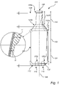
- the hollow container extends along a longitudinal center line 109, wherein the longitudinal extension of the bottom portion 101 corresponds to 5-30% of the maximum longitudinal extension of the hollow container 100, the longitudinal extension of the main portion 102 corresponds to 40-80% of the maximum longitudinal extension of the hollow container 100, and the longitudinal extension of the upper portion 103 corresponds to 5-30% of the maximum longitudinal extension of the hollow container 100.
- the step of providing a hollow container comprising molded pulp may be provided by means known to the skilled person.
- the hollow container may be provided by depositing a pulp mixture into a mold, e.g. a split-mold, activating a pressing tool, e.g. an impermeable balloon within the interior cavity of the mold such that the pulp assumes the shape of the balloon, thereby forming the interior and exterior sidewalls of the hollow container.
- the molded pulp may then be drained such that excessive water is removed.
- a process for providing a hollow container is e.g. described in WO16055073 .
- Other means for providing a hollow container comprising molded pulp are also conceivable.
- the hollow container may then be removed from the split-mold, and may be further conditioned prior to applying a powder coating onto the interior walls and, in embodiments, the exterior container walls.
- the step of depositing a polymeric powder may be achieved by means of a spraying device 107 capable of charging the polymeric powder prior to or during deposition of the polymeric powder.
- the spraying device may be a spray gun, but any spraying device capable of charging the powder prior to or during deposition of the powder can be used.
- the powder is typically charged by corona charging; i.e. the powder particles pass through a charged corona field at the tip or nozzle of the spray gun, which applies a negative (or positive) charge to each of the polymeric powder particles. This allows for the powder particles to strongly adhere to the grounded and electrically conductive surface of the container and stick thereto. The particles will predominantly adhere to the interior surface of the predetermined section(s).
- Depositing of the polymeric powder may be achieved by inserting the spraying device 107 or the nozzle 107a of the spraying device into the opening, or by arranging the spraying device or the nozzle in proximity of the opening, during spraying.
- the charged polymeric powder particles will be electrically attracted to the grounded and electrically conductive interior parts of the hollow container; i.e. the predetermined portions.
- the predetermined portion forms part of the main portion of the hollow container.
- the predetermined portion is in this figure enclosed by a grounded electrically conductive molding device 111.
- the electrical conductivity of the at least one predetermined portion 105a-d is higher than the electrical conductivity in the remaining portions of the hollow container during the polymeric powder deposition step b). Accordingly, a thicker coating will be provided in these portions.
- the interior powder coating may be provided by continuously spraying the interior of the hollow container for about 1 to 20, e.g. 2 to 10 seconds. Charged particles are blown from the nozzle 107a towards the interior walls of the container.
- the hollow container is treated with heat or irradiation under conditions that melt and/or cure the polymeric powder.
- the deposited polymeric powder coatings soften, melt and/or cure and a continuous barrier coating is provided. Accordingly, a uniform barrier coating, free from pinholes is achieved.
- the heat treatment step may vary.
- the hollow container is subject to heat treatment at a temperature of from 100°C to 300°C.
- the heat treatment time may be between 1 and 30 minutes.
- the curing step d) is performed by heating the hollow container at a temperature of from 150°C to 200°C, preferably from 170°C to 190°C for 5 to 20 minutes, preferably from 8 to 15 minutes.
- the powder coatings may be treated with ultraviolet (UV) light, which typically allows for a fast melting and/or curing of the powder coating.
- UV ultraviolet
- a thicker barrier coating will be provided on the interior surface of the predetermined portion(s) of the hollow container.
- Exemplary predetermined portions are illustrated in figure 1 and are denoted 105a-d.
- the hollow container 100 is shaped as a bottle.
- the upper portion 103 of the hollow container i.e. the bottle, comprises a shoulder portion 103a and a neck portion 103b, wherein the neck portion 103b has a smaller cross-sectional area than the main portion 102 and is configured to circumferent at least the opening 106 of the bottle, and wherein the shoulder portion 103a is arranged to taper between the main portion 102 and the neck portion 103b.
- the shoulder portion typically tapers at an angle of from about 15 to 75 degrees, e.g. from 20 to 60 degrees, between the main portion and the neck portion.
- the neck portion 103b is threaded.
- a threaded neck portion may be beneficial in various bottle applications, but the present disclosure is by no means limited to the neck portion being threaded.
- the threaded portion may have a trapezoidal configuration; i.e. a "screw thread profile", which enables a cap to be screwed thereto.
- the neck portion typically has a smaller cross-sectional area than the remaining parts of the upper portion 103 of the bottle.
- the bottom portion 101, the main portion 102, and the upper portion 102 (comprising the neck portion and the shoulder portion) of the hollow container are formed integrally.
- Figure 1 schematically illustrates examples of predetermined portion(s) of the hollow container 100.
- the predetermined portion may form part of the neck portion 103b (see 105a in figure 1 ), shoulder portion 103a (see 105b in figure 1 ), main portion 102 (not shown), and/or the bottom surface 104 (see 105c-d) of the hollow container 100.
- the hollow container it may, in embodiments be desired to have a thicker coating in at least two different portions of the interior surface of the container.
- the electrical conductivity is higher in at least two predetermined portions, wherein a first predetermined portion 105a forms part of the neck portion 103b, and wherein the second predetermined portion 105b-d forms part of the main portion 102, shoulder portion 103a or the bottom surface 104 of the hollow container during the polymeric powder deposition step b).
- the at least one predetermined portion 105a-d of the hollow container 100 may be arranged in contact with a grounded electrically conductive material during the step b) of polymeric powder deposition.
- the electrically conductive material may be a metal wire 108 configured to be wrapped around the at least one predetermined portion 105a-d during the polymeric powder deposition step b).
- the metal wire 108 may be wrapped around the predetermined portion 105a forming part of the neck portion 103b of the hollow container. Alternatively, or in addition, the metal wire 108 may be wrapped around the predetermined portion 105b forming part of the shoulder portion 103a of the hollow container.
- the metal wire 108 may be wrapped to cover a larger surface area, e.g. to cover the predetermined portion 105b forming part of the shoulder portion 103a in figure 1 .
- the metal wire 108 may be wrapped to cover a smaller surface area, as illustrated with respect to the neck portion 103b in figure 1 .
- the first predetermined portion 105a is larger than the second predetermined portion 105b.
- the electrically conductive material is at least one piece of metal arranged to contact the at least one predetermined portion 105a-d of the hollow container 100 during the polymeric powder deposition step b).
- the predetermined portions 105c-d form part of the bottom surface 104 of the hollow container 100.
- two metal pieces 110 may be arranged to contact the predetermined portions 105c and 105d.
- the metal pieces 110 may form part of a support device 112.
- the support device may comprise an electrically insulating material, such as plastic, in the areas surrounding the metal pieces 110.
- This construction may be beneficial if a more localized barrier coating is desired. For example, this construction may be desirable to protect sharp dents and edges of the bottom surface 104.
- the metal piece 110 is not limited to a particular size or shape.
- a metal piece may also be arranged on the main portion 102 of the hollow container 100 (not shown).
- the size of the metal piece may be larger, and the purpose of providing a thicker interior coating in this portion may be to protect the area where a label or a print is to be arranged.
- a thicker coating may also be favorable to protect dents or sharp corners resulting from e.g. embossing or debossing.
- the electrically conductive material is a grounded electrically conductive molding device 111 configured to enclose a portion of the main portion 102 and/or the shoulder portion 103a of the hollow container 100.
- the molding device may comprise a metal, such as aluminum.
- the electrical charged carried by the grounded surface will be spread across a larger area of the interior surface of the predetermined portion. Accordingly, an even powder coating will be applied across the interior surface of the predetermined portion of the hollow container.
- the molding device 111 may be configured to enclose the upper portion 103 or the bottom portion 101 of the hollow container.
- the method further comprises the step of:
- the exterior surface of the upper portion, particularly the neck portion; i.e. the portion surrounding the opening of the container is preferably coated as this part of the container is exposed to a lot of moist and liquid.
- the polymeric powder deposition step b') is performed prior to the step c) of heating or irradiating the hollow container.
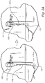
- Figure 2b illustrates the step of depositing a polymeric powder onto the exterior surface of the upper portion 103 of the container 100.
- the spraying device is removed from the opening or the interior of the container.
- the spraying device may either be inserted into the opening or arranged in proximity of the opening during spraying.
- the spraying device 107 is removed from the container opening and arranged at the distance, d1, from the opening of the container.
- the tip of the spraying spraying device e.g. of the spraying nozzle 107a is typically arranged vertically from the opening of the container; i.e. along the longitudinal center line of the container.
- the axial distance, d1, from the tip of the spraying device to the opening of the container may be from 30 to 250 mm, e.g. from 60 to 150 mm. This is to secure coverage of the powder on a large surface of the neck portion (and of the upper portion) of the hollow container.
- the polymeric powder deposition steps b) and c) are performed simultaneously.
- the hollow container 100 has a moisture content corresponding to conditioning at an ambient relative humidity of from 30 to 100%, during the step(s) of polymeric powder deposition.
- moisture content corresponding to conditioning at an ambient relative humidity means that the moisture content of the container has reached the humidity that corresponds to an equilibrium with the surrounding atmosphere at room temperature.
- the term reflects the amount of moisture contained by the material of the hollow container when it is in equilibrium with that of the surrounding atmosphere and where the container will not gain or lose moisture to the atmosphere.
- the moisture content may be lower, corresponding to conditioning at an ambient relative humidity in the range of from 30 to 55%. If an even coating, distributed on a larger surface is desired, the moisture content is in the higher range, corresponding to conditioning at an ambient relative humidity in the range of from 60 to 100%, e.g. from 75 to 95 %.
- the polymeric powder barrier coating of the present disclosure may then be applied across the entire interior surface of the container, but will be thicker in the predetermined portions where the electrical conductivity is higher.
- the moisture content in the above mentioned range allows for the exterior surface of the upper portion of the container to be coated directly after (or simultaneously with) the polymeric powder deposition step b) prior to curing or melting the polymeric powder. Accordingly, only one heating or irradiation step is required in the method.
- the method may comprise a step of:
- the conditioning time may be at least 2 hours, e.g. at least 10 hours, preferably at least 15 hours at an ambient relative humidity of from 30 to 100%, e.g. from 50 to 95%, e.g. from 50 to 90%.
- the hollow container may be conditioned at room temperature.
- the polymeric powder deposition step b) is typically performed directly after the step of conditioning to maintain the relative humidity of the hollow container during powder coating.
- the moisture content may be selectively steered and controlled depending on the size of the container, the use of the container and the specific purpose of the powder coating. For example, in some situations, it may be desired to provide a thick localized coating in a selected part; i.e. a predetermined portion of the container. In other circumstances, an evenly distributed coating is desired, but with localized thicker regions in specific parts; i.e. predetermined portions of the container. Also, the proportion of powder coating onto the exterior surface of the sidewalls of the upper container can be tailored and adapted to meet the particular needs and requirements.
- a hollow container wherein the hollow container 100 comprises a bottom portion 101, a main portion 102, and an upper portion 103, wherein the main portion 102 is arranged between the bottom portion 101 and the upper portion 103, wherein the hollow container comprises a bottom surface 104 and sidewalls 105 extending from the bottom surface 104 to an opening 106 of the hollow container; the sidewalls 105 and the bottom surface 104 defining an interior surface comprises a barrier coating comprising polymeric powder, wherein the thickness, t1, of the barrier coating in at least one predetermined portion of the hollow container is higher than the thickness, t2, of the barrier coating in the remaining portions of the hollow container 100.
- the container is preferably formed by the method described hereinbefore.
- the upper portion 103 comprises a shoulder portion 103a and a neck portion 103b, wherein the neck portion 103b has a smaller cross-sectional area than the main portion 102 and is configured to circumferent at least the opening 106 of the container, and wherein the shoulder portion 103a is arranged to taper between the main portion 102 and the neck portion 103b, wherein the predetermined portion forms part of the neck portion 103b, shoulder portion 103a, main portion 102 or bottom surface 104 of the hollow container 100.
- the thickness, t1, of the barrier coating of the at least one predetermined portion 105a-d may at least 10% higher, preferably at least 20% higher than the thickness, t2, of the barrier coating in the remaining portions of the hollow container.
- the thickness, t1, of the barrier coating in the predetermined portion may be in the range of from 10 to 200 ⁇ m, e.g. from 30 to 120 ⁇ m.
- the thickness, t2, of the barrier coating in the remaining portions may be in the range of 5 to 150 ⁇ m, e.g. from 10 to 80 ⁇ m.
- the exterior surface of the of the upper portion 103 of the hollow container 100 may comprise a barrier coating.
- the exterior surface of the main and the bottom portion of the bottle does not comprise any barrier coating. This is to achieve a "raw" paper like appearance, free from gloss, on the exterior surface of the main portion of the container. Accordingly, only the most vulnerable portions of the container are provided with a barrier coating.
- Tests were performed to illustrate that the coating thickness can be optimized in predetermined portions of two different paper sheets by means of positioning one or a plurality of grounded and electrically conductive metal pieces to predetermined positions of the sheets.
- the paper sheets were fastened on a plastic board.
- the plastic board was cut out in the portions where the grounded electrically conductive material (in this case metal pieces) were to be arranged.
- the polymeric powder was sprayed onto the sheets at a distance of about 100 mm for a time period of three seconds, while moving the gun downwards.
- the weight of each sheet was measured before and after the spray sequence.
- the sheets were subject to heat treatment in an oven at 180 ⁇ 10°C for 10 min. After heat treatment, the thickness at each dot was again measured and reported.
- the coated area was concentrated to the position of the metal piece.
- the coating extended about 20 mm from the edges of the metal piece.
- the thickness at the 20 dots was measured.
- a coating thickness of about 100 ⁇ m was measured for the dots located at the metal piece.
Landscapes
- Engineering & Computer Science (AREA)
- Mechanical Engineering (AREA)
- Manufacturing & Machinery (AREA)
- Ceramic Engineering (AREA)
- Details Of Rigid Or Semi-Rigid Containers (AREA)
- Containers Having Bodies Formed In One Piece (AREA)
- Application Of Or Painting With Fluid Materials (AREA)
Priority Applications (7)
| Application Number | Priority Date | Filing Date | Title |
|---|---|---|---|
| EP21166394.3A EP4067572A1 (de) | 2021-03-31 | 2021-03-31 | Verfahren zur bereitstellung einer ungleichmässigen sperrbeschichtung auf einem hohlen behälter mit geformter pulpe |
| PL22718204.5T PL4314409T3 (pl) | 2021-03-31 | 2022-03-25 | Sposób otrzymywania niejednolitej powłoki barierowej na pustym pojemniku zawierającym formowaną masę celulozową |
| US18/551,940 US20240167229A1 (en) | 2021-03-31 | 2022-03-25 | A method for providing a non-uniform barrier coating on a hollow container comprising molded pulp |
| CN202280027092.5A CN117120688B (zh) | 2021-03-31 | 2022-03-25 | 用于在中空容器上设置非均匀阻隔涂层的方法和中空容器 |
| PCT/EP2022/057990 WO2022207508A1 (en) | 2021-03-31 | 2022-03-25 | A method for providing a non-uniform barrier coating on a hollow container comprising molded pulp |
| EP22718204.5A EP4314409B1 (de) | 2021-03-31 | 2022-03-25 | Verfahren zur bereitstellung einer ungleichmässigen sperrbeschichtung auf einem hohlen behälter mit geformter pulpe |
| ES22718204T ES3037682T3 (en) | 2021-03-31 | 2022-03-25 | A method for providing a non-uniform barrier coating on a hollow container comprising molded pulp |
Applications Claiming Priority (1)
| Application Number | Priority Date | Filing Date | Title |
|---|---|---|---|
| EP21166394.3A EP4067572A1 (de) | 2021-03-31 | 2021-03-31 | Verfahren zur bereitstellung einer ungleichmässigen sperrbeschichtung auf einem hohlen behälter mit geformter pulpe |
Publications (1)
| Publication Number | Publication Date |
|---|---|
| EP4067572A1 true EP4067572A1 (de) | 2022-10-05 |
Family
ID=75625291
Family Applications (2)
| Application Number | Title | Priority Date | Filing Date |
|---|---|---|---|
| EP21166394.3A Withdrawn EP4067572A1 (de) | 2021-03-31 | 2021-03-31 | Verfahren zur bereitstellung einer ungleichmässigen sperrbeschichtung auf einem hohlen behälter mit geformter pulpe |
| EP22718204.5A Active EP4314409B1 (de) | 2021-03-31 | 2022-03-25 | Verfahren zur bereitstellung einer ungleichmässigen sperrbeschichtung auf einem hohlen behälter mit geformter pulpe |
Family Applications After (1)
| Application Number | Title | Priority Date | Filing Date |
|---|---|---|---|
| EP22718204.5A Active EP4314409B1 (de) | 2021-03-31 | 2022-03-25 | Verfahren zur bereitstellung einer ungleichmässigen sperrbeschichtung auf einem hohlen behälter mit geformter pulpe |
Country Status (6)
| Country | Link |
|---|---|
| US (1) | US20240167229A1 (de) |
| EP (2) | EP4067572A1 (de) |
| CN (1) | CN117120688B (de) |
| ES (1) | ES3037682T3 (de) |
| PL (1) | PL4314409T3 (de) |
| WO (1) | WO2022207508A1 (de) |
Cited By (2)
| Publication number | Priority date | Publication date | Assignee | Title |
|---|---|---|---|---|
| WO2024046976A1 (de) * | 2022-08-30 | 2024-03-07 | Alpla Werke Alwin Lehner Gmbh & Co. Kg | Verfahren zum beschichten eines getrockneten rohlings |
| WO2024074682A1 (de) * | 2022-10-06 | 2024-04-11 | Alpla Werke Alwin Lehner Gmbh & Co. Kg | Vorrichtung zur beschichtung von faserbasierten hohlkörpern |
Families Citing this family (1)
| Publication number | Priority date | Publication date | Assignee | Title |
|---|---|---|---|---|
| DE102022134098A1 (de) * | 2022-12-20 | 2024-06-20 | Krones Aktiengesellschaft | Verfahren zum Herstellen eines Fasern umfassenden Behälters mit einer Fasern umfassenden Krempe, Fasern umfassender Behälter und Vorrichtung zum Ausführen des Verfahrens |
Citations (5)
| Publication number | Priority date | Publication date | Assignee | Title |
|---|---|---|---|---|
| US5997643A (en) * | 1994-02-18 | 1999-12-07 | Nordson Corporation | Apparatus for powder coating welding cans |
| WO2010144340A1 (en) * | 2009-06-11 | 2010-12-16 | Ellery West | Paper container having a reinforced neck |
| WO2016055072A1 (en) | 2014-10-08 | 2016-04-14 | Ecoxpac A/S | A system and a method for producing a molded article, such as a tray |
| WO2016055073A1 (en) | 2014-10-08 | 2016-04-14 | Ecoxpac A/S | A system and a method for producing a molded article, such as a bottle |
| WO2019175610A1 (en) * | 2018-03-16 | 2019-09-19 | Longcroft James Henry Stoddart | Biodegradable coatings for biodegradable substrates |
Family Cites Families (6)
| Publication number | Priority date | Publication date | Assignee | Title |
|---|---|---|---|---|
| US4211339A (en) * | 1976-12-13 | 1980-07-08 | Onoda Cement Co., Ltd. | Laminated paper container with sealed seams |
| DE2914960B1 (de) * | 1979-04-12 | 1980-10-16 | Gema Ag Appbau | Verfahren und Vorrichtung zum Spruehbeschichten des Inneren von eine Naht aufweisenden rohrfoermigen Koerpern |
| US4496415A (en) * | 1982-04-08 | 1985-01-29 | Westinghouse Electric Corp. | Method for impregnating resin powder directly into a laminate lay up |
| JP2000109077A (ja) * | 1998-10-06 | 2000-04-18 | Kao Corp | 中空容器 |
| DE102017214469A1 (de) * | 2017-08-18 | 2019-02-21 | Sig Technology Ag | Ein Verfahren zum Herstellen eines Behälters aus einem Behälterrohling, insbesondere mit einem Verringern einer Höhe des Behälterrohlings |
| CN114126771A (zh) * | 2019-07-17 | 2022-03-01 | 3M创新有限公司 | 形成图案化涂层的涂覆方法和系统 |
-
2021
- 2021-03-31 EP EP21166394.3A patent/EP4067572A1/de not_active Withdrawn
-
2022
- 2022-03-25 CN CN202280027092.5A patent/CN117120688B/zh active Active
- 2022-03-25 EP EP22718204.5A patent/EP4314409B1/de active Active
- 2022-03-25 PL PL22718204.5T patent/PL4314409T3/pl unknown
- 2022-03-25 ES ES22718204T patent/ES3037682T3/es active Active
- 2022-03-25 WO PCT/EP2022/057990 patent/WO2022207508A1/en not_active Ceased
- 2022-03-25 US US18/551,940 patent/US20240167229A1/en active Pending
Patent Citations (5)
| Publication number | Priority date | Publication date | Assignee | Title |
|---|---|---|---|---|
| US5997643A (en) * | 1994-02-18 | 1999-12-07 | Nordson Corporation | Apparatus for powder coating welding cans |
| WO2010144340A1 (en) * | 2009-06-11 | 2010-12-16 | Ellery West | Paper container having a reinforced neck |
| WO2016055072A1 (en) | 2014-10-08 | 2016-04-14 | Ecoxpac A/S | A system and a method for producing a molded article, such as a tray |
| WO2016055073A1 (en) | 2014-10-08 | 2016-04-14 | Ecoxpac A/S | A system and a method for producing a molded article, such as a bottle |
| WO2019175610A1 (en) * | 2018-03-16 | 2019-09-19 | Longcroft James Henry Stoddart | Biodegradable coatings for biodegradable substrates |
Cited By (4)
| Publication number | Priority date | Publication date | Assignee | Title |
|---|---|---|---|---|
| WO2024046976A1 (de) * | 2022-08-30 | 2024-03-07 | Alpla Werke Alwin Lehner Gmbh & Co. Kg | Verfahren zum beschichten eines getrockneten rohlings |
| CH720000A1 (de) * | 2022-08-30 | 2024-03-15 | Alpla Werke Alwin Lehner Gmbh & Co Kg | Verfahren zum Beschichten eines getrockneten Rohlings. |
| WO2024074682A1 (de) * | 2022-10-06 | 2024-04-11 | Alpla Werke Alwin Lehner Gmbh & Co. Kg | Vorrichtung zur beschichtung von faserbasierten hohlkörpern |
| CH720096A1 (de) * | 2022-10-06 | 2024-04-15 | Alpla Werke Alwin Lehner Gmbh & Co Kg | Vorrichtung zur Beschichtung von faserbasierten Hohlkörpern. |
Also Published As
| Publication number | Publication date |
|---|---|
| EP4314409C0 (de) | 2025-06-18 |
| WO2022207508A1 (en) | 2022-10-06 |
| PL4314409T3 (pl) | 2025-08-18 |
| EP4314409B1 (de) | 2025-06-18 |
| CN117120688B (zh) | 2026-03-24 |
| CN117120688A (zh) | 2023-11-24 |
| ES3037682T3 (en) | 2025-10-06 |
| EP4314409A1 (de) | 2024-02-07 |
| US20240167229A1 (en) | 2024-05-23 |
Similar Documents
| Publication | Publication Date | Title |
|---|---|---|
| EP4314409B1 (de) | Verfahren zur bereitstellung einer ungleichmässigen sperrbeschichtung auf einem hohlen behälter mit geformter pulpe | |
| EP4314408B1 (de) | Verfahren zum beschichten eines hohlen behälters mit geformter pulpe | |
| US3032816A (en) | Coating process and apparatus | |
| US20100227094A1 (en) | Oxygen barrier molded container and method for production thereof | |
| WO2011083342A4 (en) | Sealable container, sealed container and processes for making a sealable container and a sealed container | |
| AU2008295108A1 (en) | Packaging component and process for producing it | |
| CA2797882A1 (en) | Method for improving the heat sealability of packaging material and method for manufacturing heat-sealed container or package | |
| KR20190133693A (ko) | 담배들에 대한 수분-보유, 품질-보존 및 향기-유지 진공 알루미늄-도금 내부 라이너 및 이의 제조 프로세스 | |
| CA2142237A1 (en) | Powder Coating Edge Primer | |
| US3968279A (en) | Method for applying plastisol coating of uniform thickness to glass containers | |
| US20050220997A1 (en) | Method and device for producing hollow bodies | |
| DE69333126D1 (de) | Wärmeformbares leitendes laminat und dessen herstellungsverfahren | |
| CN119998048A (zh) | 用于涂覆纤维基中空主体的装置 | |
| CA2695334C (en) | An oxygen barrier molded container and method for production thereof | |
| JP7153382B1 (ja) | 容器の製造方法 | |
| CN113578592B (zh) | 纸塑包装结构的制备方法、及喷涂工装 | |
| AU2021339039B2 (en) | Food packaging | |
| CA2752155A1 (en) | An oxygen barrier molded container and method for production thereof | |
| MXPA01011021A (es) | Envase de tubo de poliested decorado para composiciones acuosas. | |
| CA2714747A1 (en) | An oxygen barrier molded container and method for production thereof | |
| JP2004050490A (ja) | 金属調を有する印刷された紙包装材の製造方法 | |
| JP2003112114A (ja) | コルク栓における被膜の形成方法 | |
| GB1009944A (en) | Improvements in sheet material for forming laminated dielectric bodies | |
| HK1186708A (en) | Foil stamped parts having asymmetrical edges |
Legal Events
| Date | Code | Title | Description |
|---|---|---|---|
| PUAI | Public reference made under article 153(3) epc to a published international application that has entered the european phase |
Free format text: ORIGINAL CODE: 0009012 |
|
| STAA | Information on the status of an ep patent application or granted ep patent |
Free format text: STATUS: THE APPLICATION HAS BEEN PUBLISHED |
|
| AK | Designated contracting states |
Kind code of ref document: A1 Designated state(s): AL AT BE BG CH CY CZ DE DK EE ES FI FR GB GR HR HU IE IS IT LI LT LU LV MC MK MT NL NO PL PT RO RS SE SI SK SM TR |
|
| RAP3 | Party data changed (applicant data changed or rights of an application transferred) |
Owner name: BILLERUD AKTIEBOLAG (PUBL) |
|
| STAA | Information on the status of an ep patent application or granted ep patent |
Free format text: STATUS: THE APPLICATION IS DEEMED TO BE WITHDRAWN |
|
| 18D | Application deemed to be withdrawn |
Effective date: 20230406 |