EP4067609A1 - Serrure à cylindre programmable ne nécessitant pas de clé de changement spécifique - Google Patents
Serrure à cylindre programmable ne nécessitant pas de clé de changement spécifique Download PDFInfo
- Publication number
- EP4067609A1 EP4067609A1 EP22157404.9A EP22157404A EP4067609A1 EP 4067609 A1 EP4067609 A1 EP 4067609A1 EP 22157404 A EP22157404 A EP 22157404A EP 4067609 A1 EP4067609 A1 EP 4067609A1
- Authority
- EP
- European Patent Office
- Prior art keywords
- key
- insert
- programming
- lock
- rotor
- Prior art date
- Legal status (The legal status is an assumption and is not a legal conclusion. Google has not performed a legal analysis and makes no representation as to the accuracy of the status listed.)
- Granted
Links
Images



Classifications
-
- E—FIXED CONSTRUCTIONS
- E05—LOCKS; KEYS; WINDOW OR DOOR FITTINGS; SAFES
- E05B—LOCKS; ACCESSORIES THEREFOR; HANDCUFFS
- E05B29/00—Cylinder locks and other locks with plate tumblers which are set by pushing the key in
- E05B29/004—Cylinder locks and other locks with plate tumblers which are set by pushing the key in with changeable combinations
-
- E—FIXED CONSTRUCTIONS
- E05—LOCKS; KEYS; WINDOW OR DOOR FITTINGS; SAFES
- E05B—LOCKS; ACCESSORIES THEREFOR; HANDCUFFS
- E05B27/00—Cylinder locks or other locks with tumbler pins or balls that are set by pushing the key in
- E05B27/005—Cylinder locks or other locks with tumbler pins or balls that are set by pushing the key in with changeable combinations
-
- E—FIXED CONSTRUCTIONS
- E05—LOCKS; KEYS; WINDOW OR DOOR FITTINGS; SAFES
- E05B—LOCKS; ACCESSORIES THEREFOR; HANDCUFFS
- E05B27/00—Cylinder locks or other locks with tumbler pins or balls that are set by pushing the key in
- E05B27/0003—Details
- E05B27/0017—Tumblers or pins
-
- E—FIXED CONSTRUCTIONS
- E05—LOCKS; KEYS; WINDOW OR DOOR FITTINGS; SAFES
- E05B—LOCKS; ACCESSORIES THEREFOR; HANDCUFFS
- E05B27/00—Cylinder locks or other locks with tumbler pins or balls that are set by pushing the key in
- E05B27/0039—Cylinder locks or other locks with tumbler pins or balls that are set by pushing the key in with pins which slide and rotate about their axis
-
- E—FIXED CONSTRUCTIONS
- E05—LOCKS; KEYS; WINDOW OR DOOR FITTINGS; SAFES
- E05B—LOCKS; ACCESSORIES THEREFOR; HANDCUFFS
- E05B47/00—Operating or controlling locks or other fastening devices by electric or magnetic means
- E05B47/0038—Operating or controlling locks or other fastening devices by electric or magnetic means using permanent magnets
-
- E—FIXED CONSTRUCTIONS
- E05—LOCKS; KEYS; WINDOW OR DOOR FITTINGS; SAFES
- E05B—LOCKS; ACCESSORIES THEREFOR; HANDCUFFS
- E05B29/00—Cylinder locks and other locks with plate tumblers which are set by pushing the key in
- E05B29/0066—Side bar locking
-
- E—FIXED CONSTRUCTIONS
- E05—LOCKS; KEYS; WINDOW OR DOOR FITTINGS; SAFES
- E05B—LOCKS; ACCESSORIES THEREFOR; HANDCUFFS
- E05B31/00—Cylinder locks with both tumbler pins or balls and plate tumblers
Definitions
- the present invention concerns a programmable cylinder lock, namely a lock comprising devices intended to allow, through a change operation, to modify the former lock codification in order to adapt the lock for being operated by a key different from the key to which the lock was formerly adapted More particularly, the invention concerns improvements in a kind of programmable cylinder lock which is known from the European Patents N° 0.226.252 and 0.900.310 and n° 2.529.068 .
- the kind of locks to which applies the present invention is a lock with a programming device, which comprises a stator, a cavity provided in said stator, a rotor rotatably mounted in said stator cavity and a keyhole hollowed in said rotor, and wherein the programming device comprises in the stator a longitudinal groove made in said stator cavity and a series of stator seats, which in case can contain counter-pins and the respective springs, and comprises in the rotor:
- the change bar automatically moves outwards, disengaging the key followers from the locking pins, every time the key is brought into the change position.
- the lock is inadvertently deprogrammed by removing the key when it is in the change position, even if the user does not intend to perform a new programming.
- a general drawback of programmable locks consists in that, if the key intended to program the lock is inserted in an incomplete way, the lock receives a faulty programming which is then not easy to correct.
- Document EP 2,529,068 describes a reprogrammable lock with an initial key, a change bar and a new key i.e. without the aforementioned special change key.
- the change bar is normally kept in a misaligned position with respect to the rotor axis by means of a spring arranged asymmetrically with respect to the midpoint of the bar itself. In this position, the change bar maintains the engagement between the key followers and the pins in the closest region to the opening for the introduction of the key. These key followers are therefore locked for movement in their respective first rotor seats and this is sufficient to prevent the retraction of the initial key.
- the change bar retracts completely in the groove of the stator disengaging from the pins all the key followers which, having therefore become mobile in the first place, allow the extraction of the initial key and the subsequent insertion of the new key which will provide the new mapping of the lock.
- This mapping is mechanically stored when the user, by turning the new key angularly, rotates the change bar outside the stator groove. This causes the radial movement of the change bar towards the axis of rotor and the engagement of all the key followers, arranged according to the mapping of the new key, with their respective locking pins.
- the present invention has the scope of improving the user experience of a lock as previously described since for some users the use of the change rod, which requires a certain precision and can therefore be complicated, for example in conditions of poor lighting.
- the present invention has the general purpose of improving known locks of the type referred to, so as to remedy the drawbacks indicated.
- the invention has the main purpose of achieving the desired programming operation with greater simplicity even in poor lighting conditions and, at the same time, allowing the use of keys normally available on the market without resorting to special keys e.g. the change key.
- a mechanical reprogrammable lock provided with a reprogramming tool
- the latter comprises a stop movable between an advanced position in which the programming insert is locked so that the key followers and locking pins are engaged and in a retracted position in which the programming insert is elastically pushed into the reprogramming position and wherein the stop comprises a magnetic material and also the tool is magnetic and of such polarity as to bring the stop into the retracted position when approached to the rotor.
- the programming insert is movable in the radial direction in the rotor to couple / uncouple the toothed locking pins and key followers; and the stop is movable in the axial direction between the extracted and retracted position. In this way, the force applied to disengage the stop from the programming insert is independent of the force required to move the programming insert towards the programming position.
- a lock of the kind to which the invention is applied includes, in an embodiment, a stator 1 having a cylindrical bore 2 for a rotor 9; along bore 2 extends, at least in correspondence of the programming device, a longitudinal side groove 3.
- stator 1 has a recess 4 for receiving a ring 5 with a web 6 forming a part of the operative member of the lock, but in other embodiments this web 6 can be replaced by different members, for example by cams.
- Stator 1 also has vertical channels 7 and 8 intended to house counter-pins 31 of the lock.
- Rotor 9 is cylindrical and it has a keyhole 10 for inserting an initial key C.
- Rotor 9 is installed inside bore 2 of stator 1.
- Rotor 9 includes a series of first seats 12 intersecting keyhole 10 for the key C, and it includes a series of second seats 13, parallel to first seats 12 , a first slot 14 and a second slot 15, orthogonal with respect to said seats and parallel to the rotor axis.
- a key follower 16 is inserted with longitudinal and transversal mobility in one of said first rotor seats 12 for cooperating with the conformations of key C inserted in said keyhole 10.
- the key follower 16 is provided on one side with projections 17 and on the opposite side with an element 18 for sliding engagement, and it is associated with a spring 19 which stresses the key follower towards the keyhole 10.
- a locking pin 20 is slidingly inserted in one of said second rotor seats 13, and it is provided with a series of first recesses 21 facing said projections 17 of key follower 16, and with a series of second recesses 22 facing the side opposite said key follower 16.
- a stop bar 23 is inserted in said first rotor slot 14, and it has projections 24 facing said second recesses 22 of the locking pins 20, and a projection 25 facing the side opposite said locking pins and suitable for cooperating with said stator groove 3. Stop bar 23 is associated with first springs 26 which stress the stop bar outwards.
- a change bar 27 or programming insert is inserted in said second orthogonal rotor slot 15, and it is provided with slidable engagement elements 28 engaged with said sliding engagement elements 18 of key followers 16, and with a projection facing the side opposite key followers 16 and suitable for cooperating with said stator groove 3.
- change bar 27, in the known embodiments is associated with one or more springs biasing the change bar outwards. Such springs, or at least a part of them, may be omitted in certain embodiments of the present invention.
- a counter-pin 31 is inserted in the stator channel 8 for cooperating with the locking pin 20.
- the counter-pin 31 is pushed by a spring 32 which, by means of a little block 33, rests against a retainment bar 34 inserted in a corresponding stator hole.
- Such counter-pins 31 may be foreseen in order to give more strength to the lock, however they are not necessary and may be omitted.
- change bar 27 is with its projection corresponding to the stator groove 3.
- this latter is not completely displaced outwards and at least some toothings 17 of key followers 16 remain engaged with the teeth 21 of the locking pins 20, which are blocked in their position by stop bar 23 which, no more corresponding to the groove 3, maintains mutually engaged toothings 22 and 24. Therefore, in this position it is not possible to unintentionally extract key C and lose the lock programming.
- the lock may include mechanisms with locking pins and counter-pins of conventional type, which in the example are represented by locking pins 41 inserted into bores 1 of rotor 9, by counter-pins 42, springs 43 and rest blocks 44 inserted in channels 7 of stator 1 and kept in place by retainment bars 35.
- locking pins 41 inserted into bores 1 of rotor 9, by counter-pins 42, springs 43 and rest blocks 44 inserted in channels 7 of stator 1 and kept in place by retainment bars 35.
- the lock according to the invention may be included the mechanisms characteristic of the locks with master keys, wherein the locking pins 45 are divided in two or more sections in their regions near the surface separating them from the counter-pins 46.
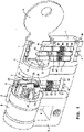
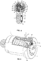
- Figures from 6 to 9 show a particular embodiment of the change means intended to push outwards change bar 27 when the user, after having brought the key C in the change position, intends to provide a new programming of the lock.
- Figure 6 shows in a perspective view the lock with the correspondent key C not yet inserted into the lock.
- rotor 9 carries an insert 49 movable between an extracted position wherein an end portion 50 of change bar 27 is engaged ( Figure 6 ) and a retracted position wherein change bar 27 and insert 49 are disengaged ( Figure 7 ).
- change bar 27 is engaged, at least one or more pairs of key followers and pins 16, 20 are coupled e.g. radially coupled, in particular at least the pair of key follower and pin proximal to keyhole 10 is coupled so as to block the movement of the correspondent key follower and keep key C locked in rotor 9.
- Figure 7 shows a condition similar to that of Figure 5 i.e. in the angular change position by means of initial key C, change bar 27 is pushed into groove 3 of the stator by the one or more springs after insert 49, which comprises a magnetic material, is brought into the retracted position by means of a magnet 51, thus disengaging end portion 50. Now all key followers 16 and pins 20 are decoupled and it is possible to remove initial key C to reprogram the lock.
- key followers 16 are still free to move and are arranged along the new mapping thanks to the action of springs 19.
- end portion 50 and insert 49 are again aligned and it is possible to restore the coupling e.g. shape coupling, between insert 49 and change bar 27.
- insert 49 is kept in the extracted position by means of a spring 53.
- spring 53 automatically pushes insert 49 inside a suitable cavity 54 of change bar 27.
- the direction of movement of insert 49 is transverse to that of the change bar 27, in particular the first is substantially axial, the second substantially radial.
- change bar 27 carries a permanent magnet which attracts insert 49 in the extracted position when change bar 27 is completely out of groove 3 of the stator.
- the magnetic field of magnet 51 must be more intense than that of change bar 27 in order to retract insert 49 when necessary.
- Figure 9 shows the angular position of the change and the action of radial springs 55 pushing change bar 27 into the groove 3.
Landscapes
- Physics & Mathematics (AREA)
- Electromagnetism (AREA)
- Lock And Its Accessories (AREA)
Applications Claiming Priority (1)
| Application Number | Priority Date | Filing Date | Title |
|---|---|---|---|
| IT102021000005276A IT202100005276A1 (it) | 2021-03-05 | 2021-03-05 | Serratura a cilindro programmabile che non richiede una chiave speciale di cambio |
Publications (3)
| Publication Number | Publication Date |
|---|---|
| EP4067609A1 true EP4067609A1 (fr) | 2022-10-05 |
| EP4067609C0 EP4067609C0 (fr) | 2023-12-13 |
| EP4067609B1 EP4067609B1 (fr) | 2023-12-13 |
Family
ID=75769955
Family Applications (1)
| Application Number | Title | Priority Date | Filing Date |
|---|---|---|---|
| EP22157404.9A Active EP4067609B1 (fr) | 2021-03-05 | 2022-02-18 | Serrure à cylindre programmable ne nécessitant pas de clé de changement spécifique |
Country Status (7)
| Country | Link |
|---|---|
| US (2) | US11970879B2 (fr) |
| EP (1) | EP4067609B1 (fr) |
| AU (1) | AU2022201259A1 (fr) |
| CA (1) | CA3147053A1 (fr) |
| ES (1) | ES2974325T3 (fr) |
| IT (1) | IT202100005276A1 (fr) |
| MX (1) | MX2022002483A (fr) |
Citations (4)
| Publication number | Priority date | Publication date | Assignee | Title |
|---|---|---|---|---|
| EP0226252A2 (fr) | 1985-12-19 | 1987-06-24 | RIELDA SERRATURE s.r.l. | Serrure à cylindre avec clé interchangeable |
| EP0900310A1 (fr) | 1997-03-10 | 1999-03-10 | Rielda S.R.L. | Serrure a barillet programmable pourvu de clefs passe-partout |
| US20060101880A1 (en) * | 2004-11-12 | 2006-05-18 | Ward-Dolkas Paul C | Re-keyable lock cylinder |
| EP2529068A1 (fr) | 2010-01-27 | 2012-12-05 | Rielda Serrature S.r.L. | Serrure à cylindre programmable comprenant un dispositif de sécurité pour éviter la programmation défectueuse |
Family Cites Families (5)
| Publication number | Priority date | Publication date | Assignee | Title |
|---|---|---|---|---|
| US4747281A (en) * | 1986-07-02 | 1988-05-31 | Monahan Brian J | Randomly and integrally re-keyable lock apparatus and method |
| US6959569B2 (en) * | 2002-09-26 | 2005-11-01 | Newfrey Llc | Re-keyable lock assembly |
| US20060059965A1 (en) * | 2004-09-17 | 2006-03-23 | Benstead Evan A | Rekeyable lock having 2-piece pin with rotatable member |
| CA2678068C (fr) * | 2008-08-29 | 2014-04-15 | Tong Lung Metal Industry Co., Ltd. | Serrure a barillet remplacable |
| US20110041577A1 (en) * | 2009-08-18 | 2011-02-24 | Jack Zhang | Rekeyable lock assembly with blown cylinder protection |
-
2021
- 2021-03-05 IT IT102021000005276A patent/IT202100005276A1/it unknown
- 2021-06-02 US US17/336,706 patent/US11970879B2/en active Active
-
2022
- 2022-01-28 CA CA3147053A patent/CA3147053A1/fr active Pending
- 2022-02-18 ES ES22157404T patent/ES2974325T3/es active Active
- 2022-02-18 EP EP22157404.9A patent/EP4067609B1/fr active Active
- 2022-02-24 AU AU2022201259A patent/AU2022201259A1/en active Pending
- 2022-02-25 MX MX2022002483A patent/MX2022002483A/es unknown
-
2023
- 2023-12-06 US US18/530,779 patent/US12421763B2/en active Active
Patent Citations (4)
| Publication number | Priority date | Publication date | Assignee | Title |
|---|---|---|---|---|
| EP0226252A2 (fr) | 1985-12-19 | 1987-06-24 | RIELDA SERRATURE s.r.l. | Serrure à cylindre avec clé interchangeable |
| EP0900310A1 (fr) | 1997-03-10 | 1999-03-10 | Rielda S.R.L. | Serrure a barillet programmable pourvu de clefs passe-partout |
| US20060101880A1 (en) * | 2004-11-12 | 2006-05-18 | Ward-Dolkas Paul C | Re-keyable lock cylinder |
| EP2529068A1 (fr) | 2010-01-27 | 2012-12-05 | Rielda Serrature S.r.L. | Serrure à cylindre programmable comprenant un dispositif de sécurité pour éviter la programmation défectueuse |
Also Published As
| Publication number | Publication date |
|---|---|
| US20220282526A1 (en) | 2022-09-08 |
| ES2974325T3 (es) | 2024-06-26 |
| AU2022201259A1 (en) | 2022-09-22 |
| MX2022002483A (es) | 2022-09-06 |
| CA3147053A1 (fr) | 2022-09-05 |
| EP4067609C0 (fr) | 2023-12-13 |
| US20240125143A1 (en) | 2024-04-18 |
| IT202100005276A1 (it) | 2022-09-05 |
| US11970879B2 (en) | 2024-04-30 |
| EP4067609B1 (fr) | 2023-12-13 |
| US12421763B2 (en) | 2025-09-23 |
Similar Documents
| Publication | Publication Date | Title |
|---|---|---|
| EP2152986B1 (fr) | Ensemble barillet de serrure programmable | |
| EP0900310B1 (fr) | Serrure a barillet programmable pourvu de clefs passe-partout | |
| US11702862B2 (en) | Modular lock plug | |
| US8770000B2 (en) | Programmable cylinder lock which does not require a special change key | |
| EP1019601A1 (fr) | Serrure a cylindre | |
| IE59506B1 (en) | Cylinder lock with interchangeable key | |
| EP2084351A1 (fr) | Ensemble serrure à possibilité de changement de clé, et procédé de fonctionnement | |
| US20060059965A1 (en) | Rekeyable lock having 2-piece pin with rotatable member | |
| EP4067609B1 (fr) | Serrure à cylindre programmable ne nécessitant pas de clé de changement spécifique | |
| NZ785494A (en) | Programmable cylinder lock not requiring a specific change key | |
| EP1366256B1 (fr) | Serrure rotative a barre laterale et a gorge a levier dotee d'une commande de barre laterale | |
| CA3119353C (fr) | Unite de serrure a barillet et cle associee | |
| EP0902139A1 (fr) | Serrure cylindrique avec clef plate pourvue de logement pour un élément mobile | |
| HK1060606B (en) | Rotating pin tumbler side bar lock with side bar control | |
| HK1187662B (en) | Tool-less rekeyable lock cylinder |
Legal Events
| Date | Code | Title | Description |
|---|---|---|---|
| PUAI | Public reference made under article 153(3) epc to a published international application that has entered the european phase |
Free format text: ORIGINAL CODE: 0009012 |
|
| STAA | Information on the status of an ep patent application or granted ep patent |
Free format text: STATUS: THE APPLICATION HAS BEEN PUBLISHED |
|
| AK | Designated contracting states |
Kind code of ref document: A1 Designated state(s): AL AT BE BG CH CY CZ DE DK EE ES FI FR GB GR HR HU IE IS IT LI LT LU LV MC MK MT NL NO PL PT RO RS SE SI SK SM TR |
|
| STAA | Information on the status of an ep patent application or granted ep patent |
Free format text: STATUS: REQUEST FOR EXAMINATION WAS MADE |
|
| 17P | Request for examination filed |
Effective date: 20230405 |
|
| RBV | Designated contracting states (corrected) |
Designated state(s): AL AT BE BG CH CY CZ DE DK EE ES FI FR GB GR HR HU IE IS IT LI LT LU LV MC MK MT NL NO PL PT RO RS SE SI SK SM TR |
|
| RIC1 | Information provided on ipc code assigned before grant |
Ipc: E05B 31/00 20060101ALN20230531BHEP Ipc: E05B 47/00 20060101ALI20230531BHEP Ipc: E05B 29/00 20060101AFI20230531BHEP |
|
| GRAP | Despatch of communication of intention to grant a patent |
Free format text: ORIGINAL CODE: EPIDOSNIGR1 |
|
| STAA | Information on the status of an ep patent application or granted ep patent |
Free format text: STATUS: GRANT OF PATENT IS INTENDED |
|
| RIC1 | Information provided on ipc code assigned before grant |
Ipc: E05B 31/00 20060101ALN20230627BHEP Ipc: E05B 47/00 20060101ALI20230627BHEP Ipc: E05B 29/00 20060101AFI20230627BHEP |
|
| INTG | Intention to grant announced |
Effective date: 20230720 |
|
| GRAS | Grant fee paid |
Free format text: ORIGINAL CODE: EPIDOSNIGR3 |
|
| GRAA | (expected) grant |
Free format text: ORIGINAL CODE: 0009210 |
|
| STAA | Information on the status of an ep patent application or granted ep patent |
Free format text: STATUS: THE PATENT HAS BEEN GRANTED |
|
| AK | Designated contracting states |
Kind code of ref document: B1 Designated state(s): AL AT BE BG CH CY CZ DE DK EE ES FI FR GB GR HR HU IE IS IT LI LT LU LV MC MK MT NL NO PL PT RO RS SE SI SK SM TR |
|
| REG | Reference to a national code |
Ref country code: GB Ref legal event code: FG4D |
|
| REG | Reference to a national code |
Ref country code: CH Ref legal event code: EP |
|
| REG | Reference to a national code |
Ref country code: DE Ref legal event code: R096 Ref document number: 602022001245 Country of ref document: DE |
|
| REG | Reference to a national code |
Ref country code: IE Ref legal event code: FG4D |
|
| U01 | Request for unitary effect filed |
Effective date: 20240112 |
|
| U07 | Unitary effect registered |
Designated state(s): AT BE BG DE DK EE FI FR IT LT LU LV MT NL PT SE SI Effective date: 20240201 |
|
| U20 | Renewal fee for the european patent with unitary effect paid |
Year of fee payment: 3 Effective date: 20240220 |
|
| PG25 | Lapsed in a contracting state [announced via postgrant information from national office to epo] |
Ref country code: GR Free format text: LAPSE BECAUSE OF FAILURE TO SUBMIT A TRANSLATION OF THE DESCRIPTION OR TO PAY THE FEE WITHIN THE PRESCRIBED TIME-LIMIT Effective date: 20240314 |
|
| PG25 | Lapsed in a contracting state [announced via postgrant information from national office to epo] |
Ref country code: GR Free format text: LAPSE BECAUSE OF FAILURE TO SUBMIT A TRANSLATION OF THE DESCRIPTION OR TO PAY THE FEE WITHIN THE PRESCRIBED TIME-LIMIT Effective date: 20240314 |
|
| PG25 | Lapsed in a contracting state [announced via postgrant information from national office to epo] |
Ref country code: RS Free format text: LAPSE BECAUSE OF FAILURE TO SUBMIT A TRANSLATION OF THE DESCRIPTION OR TO PAY THE FEE WITHIN THE PRESCRIBED TIME-LIMIT Effective date: 20231213 Ref country code: NO Free format text: LAPSE BECAUSE OF FAILURE TO SUBMIT A TRANSLATION OF THE DESCRIPTION OR TO PAY THE FEE WITHIN THE PRESCRIBED TIME-LIMIT Effective date: 20240313 Ref country code: HR Free format text: LAPSE BECAUSE OF FAILURE TO SUBMIT A TRANSLATION OF THE DESCRIPTION OR TO PAY THE FEE WITHIN THE PRESCRIBED TIME-LIMIT Effective date: 20231213 |
|
| REG | Reference to a national code |
Ref country code: ES Ref legal event code: FG2A Ref document number: 2974325 Country of ref document: ES Kind code of ref document: T3 Effective date: 20240626 |
|
| PG25 | Lapsed in a contracting state [announced via postgrant information from national office to epo] |
Ref country code: IS Free format text: LAPSE BECAUSE OF FAILURE TO SUBMIT A TRANSLATION OF THE DESCRIPTION OR TO PAY THE FEE WITHIN THE PRESCRIBED TIME-LIMIT Effective date: 20240413 |
|
| PG25 | Lapsed in a contracting state [announced via postgrant information from national office to epo] |
Ref country code: CZ Free format text: LAPSE BECAUSE OF FAILURE TO SUBMIT A TRANSLATION OF THE DESCRIPTION OR TO PAY THE FEE WITHIN THE PRESCRIBED TIME-LIMIT Effective date: 20231213 |
|
| PG25 | Lapsed in a contracting state [announced via postgrant information from national office to epo] |
Ref country code: SK Free format text: LAPSE BECAUSE OF FAILURE TO SUBMIT A TRANSLATION OF THE DESCRIPTION OR TO PAY THE FEE WITHIN THE PRESCRIBED TIME-LIMIT Effective date: 20231213 |
|
| PG25 | Lapsed in a contracting state [announced via postgrant information from national office to epo] |
Ref country code: SM Free format text: LAPSE BECAUSE OF FAILURE TO SUBMIT A TRANSLATION OF THE DESCRIPTION OR TO PAY THE FEE WITHIN THE PRESCRIBED TIME-LIMIT Effective date: 20231213 Ref country code: SK Free format text: LAPSE BECAUSE OF FAILURE TO SUBMIT A TRANSLATION OF THE DESCRIPTION OR TO PAY THE FEE WITHIN THE PRESCRIBED TIME-LIMIT Effective date: 20231213 Ref country code: RO Free format text: LAPSE BECAUSE OF FAILURE TO SUBMIT A TRANSLATION OF THE DESCRIPTION OR TO PAY THE FEE WITHIN THE PRESCRIBED TIME-LIMIT Effective date: 20231213 Ref country code: IS Free format text: LAPSE BECAUSE OF FAILURE TO SUBMIT A TRANSLATION OF THE DESCRIPTION OR TO PAY THE FEE WITHIN THE PRESCRIBED TIME-LIMIT Effective date: 20240413 Ref country code: CZ Free format text: LAPSE BECAUSE OF FAILURE TO SUBMIT A TRANSLATION OF THE DESCRIPTION OR TO PAY THE FEE WITHIN THE PRESCRIBED TIME-LIMIT Effective date: 20231213 |
|
| PG25 | Lapsed in a contracting state [announced via postgrant information from national office to epo] |
Ref country code: PL Free format text: LAPSE BECAUSE OF FAILURE TO SUBMIT A TRANSLATION OF THE DESCRIPTION OR TO PAY THE FEE WITHIN THE PRESCRIBED TIME-LIMIT Effective date: 20231213 |
|
| PG25 | Lapsed in a contracting state [announced via postgrant information from national office to epo] |
Ref country code: PL Free format text: LAPSE BECAUSE OF FAILURE TO SUBMIT A TRANSLATION OF THE DESCRIPTION OR TO PAY THE FEE WITHIN THE PRESCRIBED TIME-LIMIT Effective date: 20231213 |
|
| REG | Reference to a national code |
Ref country code: DE Ref legal event code: R097 Ref document number: 602022001245 Country of ref document: DE |
|
| PG25 | Lapsed in a contracting state [announced via postgrant information from national office to epo] |
Ref country code: MC Free format text: LAPSE BECAUSE OF FAILURE TO SUBMIT A TRANSLATION OF THE DESCRIPTION OR TO PAY THE FEE WITHIN THE PRESCRIBED TIME-LIMIT Effective date: 20231213 |
|
| PLBE | No opposition filed within time limit |
Free format text: ORIGINAL CODE: 0009261 |
|
| STAA | Information on the status of an ep patent application or granted ep patent |
Free format text: STATUS: NO OPPOSITION FILED WITHIN TIME LIMIT |
|
| 26N | No opposition filed |
Effective date: 20240916 |
|
| PG25 | Lapsed in a contracting state [announced via postgrant information from national office to epo] |
Ref country code: IE Free format text: LAPSE BECAUSE OF NON-PAYMENT OF DUE FEES Effective date: 20240218 |
|
| PG25 | Lapsed in a contracting state [announced via postgrant information from national office to epo] |
Ref country code: IE Free format text: LAPSE BECAUSE OF NON-PAYMENT OF DUE FEES Effective date: 20240218 |
|
| U20 | Renewal fee for the european patent with unitary effect paid |
Year of fee payment: 4 Effective date: 20250219 |
|
| PGFP | Annual fee paid to national office [announced via postgrant information from national office to epo] |
Ref country code: ES Payment date: 20250303 Year of fee payment: 4 |
|
| PG25 | Lapsed in a contracting state [announced via postgrant information from national office to epo] |
Ref country code: CY Free format text: LAPSE BECAUSE OF FAILURE TO SUBMIT A TRANSLATION OF THE DESCRIPTION OR TO PAY THE FEE WITHIN THE PRESCRIBED TIME-LIMIT; INVALID AB INITIO Effective date: 20220218 |
|
| REG | Reference to a national code |
Ref country code: CH Ref legal event code: PL |
|
| PG25 | Lapsed in a contracting state [announced via postgrant information from national office to epo] |
Ref country code: CH Free format text: LAPSE BECAUSE OF NON-PAYMENT OF DUE FEES Effective date: 20250228 |
|
| PG25 | Lapsed in a contracting state [announced via postgrant information from national office to epo] |
Ref country code: TR Free format text: LAPSE BECAUSE OF FAILURE TO SUBMIT A TRANSLATION OF THE DESCRIPTION OR TO PAY THE FEE WITHIN THE PRESCRIBED TIME-LIMIT Effective date: 20231213 |