EP4067611A2 - Charnière de porte et porte - Google Patents
Charnière de porte et porte Download PDFInfo
- Publication number
- EP4067611A2 EP4067611A2 EP22150596.9A EP22150596A EP4067611A2 EP 4067611 A2 EP4067611 A2 EP 4067611A2 EP 22150596 A EP22150596 A EP 22150596A EP 4067611 A2 EP4067611 A2 EP 4067611A2
- Authority
- EP
- European Patent Office
- Prior art keywords
- hinge
- door
- receiving part
- door hinge
- horizontal direction
- Prior art date
- Legal status (The legal status is an assumption and is not a legal conclusion. Google has not performed a legal analysis and makes no representation as to the accuracy of the status listed.)
- Pending
Links
Images



Classifications
-
- E—FIXED CONSTRUCTIONS
- E05—LOCKS; KEYS; WINDOW OR DOOR FITTINGS; SAFES
- E05D—HINGES OR SUSPENSION DEVICES FOR DOORS, WINDOWS OR WINGS
- E05D7/00—Hinges or pivots of special construction
- E05D7/04—Hinges adjustable relative to the wing or the frame
- E05D7/0415—Hinges adjustable relative to the wing or the frame with adjusting drive means
-
- E—FIXED CONSTRUCTIONS
- E05—LOCKS; KEYS; WINDOW OR DOOR FITTINGS; SAFES
- E05D—HINGES OR SUSPENSION DEVICES FOR DOORS, WINDOWS OR WINGS
- E05D7/00—Hinges or pivots of special construction
- E05D7/04—Hinges adjustable relative to the wing or the frame
-
- E—FIXED CONSTRUCTIONS
- E05—LOCKS; KEYS; WINDOW OR DOOR FITTINGS; SAFES
- E05D—HINGES OR SUSPENSION DEVICES FOR DOORS, WINDOWS OR WINGS
- E05D7/00—Hinges or pivots of special construction
- E05D7/04—Hinges adjustable relative to the wing or the frame
- E05D7/0415—Hinges adjustable relative to the wing or the frame with adjusting drive means
- E05D7/0423—Screw-and-nut mechanisms
-
- E—FIXED CONSTRUCTIONS
- E05—LOCKS; KEYS; WINDOW OR DOOR FITTINGS; SAFES
- E05D—HINGES OR SUSPENSION DEVICES FOR DOORS, WINDOWS OR WINGS
- E05D3/00—Hinges with pins
- E05D3/02—Hinges with pins with one pin
- E05D2003/025—Hinges with pins with one pin having three knuckles
- E05D2003/027—Hinges with pins with one pin having three knuckles the end knuckles being mutually connected
-
- E—FIXED CONSTRUCTIONS
- E05—LOCKS; KEYS; WINDOW OR DOOR FITTINGS; SAFES
- E05D—HINGES OR SUSPENSION DEVICES FOR DOORS, WINDOWS OR WINGS
- E05D7/00—Hinges or pivots of special construction
- E05D7/04—Hinges adjustable relative to the wing or the frame
- E05D2007/0461—Hinges adjustable relative to the wing or the frame in angular arrangement to the wing or the frame
-
- E—FIXED CONSTRUCTIONS
- E05—LOCKS; KEYS; WINDOW OR DOOR FITTINGS; SAFES
- E05D—HINGES OR SUSPENSION DEVICES FOR DOORS, WINDOWS OR WINGS
- E05D7/00—Hinges or pivots of special construction
- E05D7/04—Hinges adjustable relative to the wing or the frame
- E05D2007/0476—Pocket hinges
-
- E—FIXED CONSTRUCTIONS
- E05—LOCKS; KEYS; WINDOW OR DOOR FITTINGS; SAFES
- E05D—HINGES OR SUSPENSION DEVICES FOR DOORS, WINDOWS OR WINGS
- E05D7/00—Hinges or pivots of special construction
- E05D7/04—Hinges adjustable relative to the wing or the frame
- E05D2007/0484—Hinges adjustable relative to the wing or the frame in a radial direction
-
- E—FIXED CONSTRUCTIONS
- E05—LOCKS; KEYS; WINDOW OR DOOR FITTINGS; SAFES
- E05D—HINGES OR SUSPENSION DEVICES FOR DOORS, WINDOWS OR WINGS
- E05D7/00—Hinges or pivots of special construction
- E05D7/04—Hinges adjustable relative to the wing or the frame
- E05D2007/0492—Hinges adjustable relative to the wing or the frame in three directions
-
- E—FIXED CONSTRUCTIONS
- E05—LOCKS; KEYS; WINDOW OR DOOR FITTINGS; SAFES
- E05Y—INDEXING SCHEME ASSOCIATED WITH SUBCLASSES E05D AND E05F, RELATING TO CONSTRUCTION ELEMENTS, ELECTRIC CONTROL, POWER SUPPLY, POWER SIGNAL OR TRANSMISSION, USER INTERFACES, MOUNTING OR COUPLING, DETAILS, ACCESSORIES, AUXILIARY OPERATIONS NOT OTHERWISE PROVIDED FOR, APPLICATION THEREOF
- E05Y2201/00—Constructional elements; Accessories therefor
- E05Y2201/60—Suspension or transmission members; Accessories therefor
- E05Y2201/622—Suspension or transmission members elements
- E05Y2201/638—Cams; Ramps
-
- E—FIXED CONSTRUCTIONS
- E05—LOCKS; KEYS; WINDOW OR DOOR FITTINGS; SAFES
- E05Y—INDEXING SCHEME ASSOCIATED WITH SUBCLASSES E05D AND E05F, RELATING TO CONSTRUCTION ELEMENTS, ELECTRIC CONTROL, POWER SUPPLY, POWER SIGNAL OR TRANSMISSION, USER INTERFACES, MOUNTING OR COUPLING, DETAILS, ACCESSORIES, AUXILIARY OPERATIONS NOT OTHERWISE PROVIDED FOR, APPLICATION THEREOF
- E05Y2900/00—Application of doors, windows, wings or fittings thereof
- E05Y2900/10—Application of doors, windows, wings or fittings thereof for buildings or parts thereof
- E05Y2900/13—Type of wing
- E05Y2900/132—Doors
Definitions
- the invention relates to a door hinge with a first hinge part and a second hinge part according to the preamble of claim 1. These are connected to one another so that they can swivel about a vertical door hinge axis of rotation and have a receiving part assigned to the second hinge part, the second hinge part having a holding section being adjustable in a receiving space of the accommodating part and extends toward a tape roll portion along a first horizontal direction out of the accommodating space. Provision is also made for the second hinge part to be adjustable relative to the receiving space in order to enable adjustment when a door leaf is mounted on the door frame with usually at least two of the door hinges described or also in the mounted state. Furthermore, a door with at least one such door hinge is to be specified.
- Multidimensionally adjustable door hinges are from the DE 103 56 403 B3 and the DE 43 07 067 A1 known.
- the first hinge part is provided for attachment to a door leaf and is referred to as a leaf part or leaf flap against this background.
- the second strap part forms a frame part, with the associated receiving part being referred to as the frame receiving part or strap pocket.
- a corresponding functional and conceptual assignment can also be useful within the scope of the present invention.
- the present invention specifically relates to an embodiment as described in the prior art mentioned.
- the leaf part and the frame part are connected to one another so that they can pivot about the vertical axis of rotation of the hinge.
- the assignment of the vertical direction refers while on the usual arrangement of the door hinge on a door in which a door leaf is pivotally attached to a door frame with the door hinge.
- the frame part can be adjusted in three directions relative to the frame receiving part, so that the door leaf can be adjusted relative to the door frame along a height, along a thickness direction of the closed door leaf (pressure adjustment) and horizontally in the plane of the closed door leaf (lateral position).
- the frame part is connected to the holding section about a pivot axis aligned parallel to the door hinge axis of rotation with the receiving part, with a pivoting angle between the frame part and the frame receiving part being adjustable with respect to the pivot axis by a screw means acting along a second horizontal direction.
- the screw means By actuating the screw means, the frame part can be adjusted to a certain extent, for example approximately +/-2°, relative to the frame receiving part.
- the first horizontal direction then corresponds to the thickness direction of the closed door leaf.
- the frame part extends out of the frame receiving part along the first horizontal direction. Taking the above explanations into account, it becomes clear that the frame part does not have to run exactly along the first horizontal direction, but can be tilted slightly by +/-2°, for example, as described. At least is in terms of the orientation of the frame part, the first horizontal direction, a main extension direction.
- a lateral adjusting screw is provided as the screw means acting along the second horizontal direction, which reaches through the frame receiving part, the lateral adjusting screw being fixed on the outside of the frame receiving part on the one hand by a screw head and on the other hand by a pressed washer along the second horizontal direction.
- the windage adjustment screw engages in a bolt which is rotatably arranged in a vertical bore of the frame part. Such an articulated arrangement is expedient in order to compensate for the pivoting movement of the frame part relative to the frame receiving part.
- An eccentric arrangement is provided on the holding section of the frame part for an adjustment of the frame part relative to the frame receiving part along the first horizontal direction.
- the eccentric arrangement comprises an adjustment eccentric which is arranged in an eccentric opening of the holding section and is fastened on one side to the frame receiving part with a screw.
- the adjustment cam On the opposite side, the adjustment cam has a tool holder that is accessible through an opening in the frame holder part.
- the leaf part, the frame part and the frame receiving part can be formed by cast metal, in particular die-cast zinc.
- the well-known door hinge is characterized by good functional properties and a low tendency to wear, with the production of the high-quality door hinge being associated with a significant manufacturing effort.
- a screw means in the form of a grub screw is provided for the adjustment along the second horizontal direction, which is supported in the area of a thin side wall of the strap pocket on an inside of the receiving space.
- the grub screw acts on a holding piece, on which a roller tab is fixed with a clamping piece and clamping screws.
- the holding piece, the roller tab, the clamping piece and the clamping screws together form a second hinge part within the meaning of the preamble of patent claim 1.
- the fixation is with a countersunk rivet intended.
- a certain amount of play should be provided overall.
- the object of the present invention is to simplify the manufacture of a generic door hinge and to further improve the functional properties.
- the subject of the invention and the solution to the problem are door hinges according to patent claim 1 and patent claim 6.
- the invention also relates to a door according to patent claim 13.
- a first aspect of the invention is concerned with improving the arrangement of a screw means acting along a second horizontal direction, with which a swivel angle between the second hinge part and the receiving part can be adjusted with respect to the swivel axis.
- a second aspect of the present invention relates to an improvement in an eccentric arrangement, with which the second strap part can be adjusted on the holding section along the first horizontal direction relative to the receiving part.
- the two aspects described in detail below are particularly preferably implemented in the door hinge in combination, with an adjustment along a vertical direction also being able to be provided in a manner known per se.
- the screw means is arranged at least at one of its ends in a groove running along the first horizontal direction on the inside of the receiving space.
- the screw means has a tool holder at a first end, the tool holder being accessible through an adjustment opening of the receiving part.
- the adjustment opening is expediently designed as a slot. It goes without saying that the adjustment opening is formed so large that on the one hand the tool holder is accessible, on the other hand horizontal support of the screw along the second horizontal direction on the inside of the receiving space is not affected.
- the screw means is arranged at least at one of its ends in a groove running along the first horizontal direction on the inside of the receiving space.
- a groove running along the first horizontal direction on the inside of the receiving space.
- the screw is already out during assembly of the door hinge, when the second hinge part is inserted into the receiving part.
- the associated end of the screw means is not only supported and mounted along the second horizontal direction, ie the axial direction of the screw means, but also in the vertical direction. It is particularly advantageous if a groove is assigned to each end of the screw means.
- the screwing means has a head with a collar, with the groove associated with the head merging into a narrower second groove section at a step in front of a first groove section, with the collar being supported on the step and with an inside the collar inner head portion lying unsupported in the second groove portion is exposed.
- the axial support of the screw means along the second horizontal direction then takes place on the collar and step, which are expediently arranged plane-parallel in order to enable good, even force support with little wear.
- the exposed inner head section on the other hand, is easily accessible and can be rotated without jamming.
- a particularly preferred circular-cylindrical bolt is expediently accommodated movably in an associated cylinder bore in the holding section, with the screw means engaging in an internal thread of the bolt.
- the bolt can then compensate for the setting of the pivoting angle between the second hinge part and the receiving part with respect to the pivoting axis by rotating it in the cylinder bore.
- the receiving part can have at least one fixing means, in particular in the form of a threaded pin.
- the fixing means can then be locked against the holding section to fix the pivoting movement about the pivot axis. Fixing with two fixing means is particularly preferred in order to enable particularly uniform mechanical bracing.
- a rotary pin of the eccentric arrangement extending along a second horizontal direction is supported at its two ends radially opposite the receiving body.
- a one-sided support known from the prior art there is less wear, greater accuracy and, with a suitable design, less play.
- the radial support at both ends means that it can be rotated particularly easily over the long term.
- the rotary pin In order to support the rotary pin at its two ends radially in relation to the receiving body, the rotary pin can abut associated bores or openings there in a particularly simple manner. Consequently, the pivot pin can also easily be fully inserted into the receiving body without protruding from associated side walls.
- the eccentric arrangement has a preferably barrel-shaped adjusting eccentric, with the rotary pin extending through the adjusting eccentric.
- the adjusting cam can initially be arranged loosely in an eccentric opening of the holding section, in which case the adjusting cam is accessible from at least one side of the holding body through an opening after the second strap part with the holding section has been pushed into the receiving part. From this side, the pivot pin can then be pressed into a bore of the adjusting eccentric, as a result of which the pivot pin and the adjusting eccentric are also permanently and non-rotatably connected to one another in a frictional connection.
- a form fit is additionally or alternatively possible through a corresponding contouring.
- an opening or only a recess for example in the form of a blind hole, can also be provided on the other side.
- the rotary pin has a shank and a head that protrudes radially in relation to the shank, preferably a cylinder head with a tool holder.
- the pivot pin can then be pressed in until the head on the adjustment eccentric is present.
- the rotary pin can be formed in a particularly simple manner by a conventional screw, in particular a cylinder head screw with or without a thread. If a commercially available cylinder head screw with a thread is provided, the associated bore in the adjustment eccentric is to be dimensioned in such a way that the desired non-rotatable connection is achieved when it is pressed in.
- first aspect and the second aspect are particularly preferably combined with one another in the door hinge in order to enable an adjustment along the first horizontal direction and the second horizontal direction in a particularly advantageous manner.
- second hinge part can be adjusted with a height adjustment means along the vertical direction.
- the second strap part and/or the receiving part are each formed in one piece as a cast metal part.
- the second band part and/or the receiving part are thus produced in a primary shaping process, so that different wall thicknesses, openings and other contours can be easily implemented.
- the manufacture of the second band part and/or the receiving part by the original forming process can generally be recognized without further ado on the basis of the shape and the structure. Zinc die-casting is particularly preferred.
- the first band part can also be formed in one piece as a cast metal part in the manner described.
- the subject of the invention is also a door with at least one door hinge, which is designed as described above, the first hinge part being attached to a door leaf and thus also in accordance with the prior art DE 103 56 403 B3 can be referred to as a wing part.
- the receiving part is inserted into a door frame, and the second hinge part can accordingly be referred to as a frame part.
- the 1 shows the door hinge in an exploded view so that the individual parts can be seen.
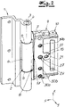
- the functioning of a three-dimensional adjustment and the freedom of movement required for this reference is made in particular to the following Figures 2 to 5 referred.
- the door hinge comprises a first hinge part 1 and a second hinge part 2, which are pivotably connected to one another about a vertical axis of rotation 3 of the hinge.
- the door hinge axis of rotation 3 runs along a vertical direction z, the two hinge parts 1 , 2 being connected in a conventional manner with a hinge bolt 4 and bushings 5 .
- the hinge pin 4 is suitably secured against falling out.
- the second band part 2 comprises a band roll section 6 and a holding section 7 adjoining it, the holding section 7 being adjustably arranged in a receiving space 8 of a receiving part 9 .
- the second belt part 2 can be adjusted in the receiving space along the vertical direction z, along a first horizontal direction x and a second horizontal direction y.
- the adjustment along the second horizontal direction y takes place by pivoting the second belt part 3 relative to the receiving part 9 about a pivot axis formed by a pivot pin 10, with the belt roller section 6 im Substantially along the second horizontal direction y is adjustable.
- the holding section 7 has a cylinder bore 11 in which a circular-cylindrical bolt 12 is inserted.
- the bolt 12 has a threaded hole 13 at about half its height, which is at the height of a vertical slot 14 of the holding section 7 in the assembled state.
- the bolt 12 is first inserted into the associated cylinder bore 11 before a screw 15 is then inserted into the threaded bore 13 .
- the screw means 15 is supported at its both ends on an inner side of the accommodation space 8 in the composite door hinge along the second horizontal direction y.
- a first groove 16 and a second groove 17 are arranged on the inside of the receiving space 8 for supporting and guiding the screw means 15 .
- the screw means 15 is designed as a simple screw and has a head 18 with a collar 19 .
- the second groove 17 associated with the head 18 transitions at a step 20 from a first groove section into a narrower second groove section, the collar 19 being supported on the step 20 and an inner head section 21 lying within the collar 19 having a tool holder provided there is exposed unsupported in the second groove portion.
- the collar 19 and the step 20 are plane-parallel and allow good force support with little wear.
- the screw means 15 is supported at both of its ends not only along the second horizontal direction y but also along the vertical direction z, the result is a particularly simple and largely play-free handling for the adjustment.
- the inner head section 21 with the tool holder is accessible through an adjustment opening 22 of the receiving part 9, the adjustment opening 22 being designed as a horizontal elongated hole, which is explained in more detail below to allow described adjustment along the first horizontal direction x.
- the adjustment along the first horizontal direction x takes place with an eccentric arrangement which has a barrel-shaped adjustment eccentric 23 and a rotary pin 24 .
- the adjustment cam 23 is first arranged in an eccentric opening 25 .
- the adjusting eccentric 23 is located at a first opening 26 and a second opening 27, which are each designed as cylindrical bores but have different sizes.
- the rotary pin 24 is then pressed into an axial bore of the adjustment eccentric 23 during assembly and is thus connected to the adjustment eccentric 23 in a non-rotatable manner in a frictional connection.
- a non-rotatable connection is basically also possible by contouring.
- the rotary pin 24 is designed as a cylinder head screw with a shank 28 and a cylinder head 29 .
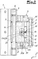
- the rotary pin 24 is pressed in so far that its ends extend in the first opening 26 and the second opening 27 and are supported there radially with respect to the receiving part 9 . Due to the support on both sides of the pivot pin 24, a particularly good, play-free mounting can be achieved permanently, with the pivot pin 24 not protruding beyond the contour of the receiving part 9 but being completely received by it (see in particular 4 ).
- a first grub screw 30a acts on a wedge element 31.
- the wedge element 31 is raised due to a wedge surface assigned to the grub screw 30a. Lowering is possible in the same way by unscrewing the grub screw 30a.
- the arrangement of the wedge element 31 with the associated grub screw 30a below the holding section 7 for height adjustment, ie for raising or lowering the second hinge part 2 in an adjustment range, is sufficient to provide the described height adjustment.
- a further upper wedge element (not shown in the figures) with an associated upper grub screw can also be provided above the holding section. After the desired height has been set, the upper wedge element can then be pressed against the holding section by screwing in the upper grub screw, as a result of which a further reduction in play and an improvement in stability are possible. Before adjusting the height, the upper wedge element may need to be loosened accordingly, in particular if the holding section 7 is to be raised relative to the receiving part 9 .
- the receiving part 9 also accommodates further grub screws 30b, with which the second hinge part can be locked in the desired setting position.
- the grub screw 30b braces the second hinge part 2 against the receiving part 9 in such a way that the adjustment described along the vertical direction z and along the first horizontal direction x and the second horizontal direction y is no longer possible or only with a considerable effort.
- the grub screws 30b should always be loosened before an adjustment.
- the first hinge part 1, the second hinge part 2 and the receiving part 9 are made of cast metal, in particular die-cast zinc.
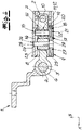
- Figures 3 to 5 illustrate the arrangement of the parts described on the assembled door hinge and their function in detail.
- the second hinge part 2 has sufficient freedom of movement along the second horizontal direction y, for example by about +/-2° with the screw means 15 along the second horizontal direction y, and strictly speaking by to be pivoted a pivot angle.
- the adjustment cam 23 is also barrel-shaped in order to ensure that the system is as even and play-free as possible despite the pivoting movement provided.
- the pivot pin 10 is movable along the first horizontal direction x in the receiving part 9, for which purpose the receiving part 9 has elongated holes 32 running horizontally there.
- the receiving space 8 extends along the vertical direction z beyond the second hinge part 2 in order to also allow a sufficient travel for a height adjustment in the vertical direction z.
- the 6 finally shows schematically the mounted door hinge on a door, the first hinge part 1 being fastened to a door leaf 33 and the receiving part 9 being inserted in a door frame 34 . Only the frame profiles of the door leaf 33 and the door frame 34 are shown.
Landscapes
- Engineering & Computer Science (AREA)
- Mechanical Engineering (AREA)
- Hinges (AREA)
Applications Claiming Priority (1)
| Application Number | Priority Date | Filing Date | Title |
|---|---|---|---|
| DE102021108209.9A DE102021108209B3 (de) | 2021-03-31 | 2021-03-31 | Türband und Tür |
Publications (2)
| Publication Number | Publication Date |
|---|---|
| EP4067611A2 true EP4067611A2 (fr) | 2022-10-05 |
| EP4067611A3 EP4067611A3 (fr) | 2022-11-23 |
Family
ID=78231657
Family Applications (1)
| Application Number | Title | Priority Date | Filing Date |
|---|---|---|---|
| EP22150596.9A Pending EP4067611A3 (fr) | 2021-03-31 | 2022-01-07 | Charnière de porte et porte |
Country Status (2)
| Country | Link |
|---|---|
| EP (1) | EP4067611A3 (fr) |
| DE (1) | DE102021108209B3 (fr) |
Cited By (2)
| Publication number | Priority date | Publication date | Assignee | Title |
|---|---|---|---|---|
| CN116812443A (zh) * | 2023-07-21 | 2023-09-29 | 四川众友机械有限责任公司 | 一种流水化生产线 |
| DE202024103866U1 (de) * | 2024-07-11 | 2025-10-14 | Simonswerk Gmbh | Türband und Tür |
Citations (2)
| Publication number | Priority date | Publication date | Assignee | Title |
|---|---|---|---|---|
| DE4307067A1 (de) | 1993-03-06 | 1994-09-08 | Heine & Sohn Anuba Beschlaege | Tür- oder Fensterband |
| DE10356403B3 (de) | 2003-12-03 | 2004-10-28 | Simonswerk, Gmbh | Mehrdimensional verstellbares Türband |
Family Cites Families (1)
| Publication number | Priority date | Publication date | Assignee | Title |
|---|---|---|---|---|
| DE29817807U1 (de) * | 1998-10-06 | 1999-06-10 | Breuer & Schmitz, 42719 Solingen | Dreidimensional verstellbares Aufschraubband für Tür- oder Fensterflügel |
-
2021
- 2021-03-31 DE DE102021108209.9A patent/DE102021108209B3/de active Active
-
2022
- 2022-01-07 EP EP22150596.9A patent/EP4067611A3/fr active Pending
Patent Citations (2)
| Publication number | Priority date | Publication date | Assignee | Title |
|---|---|---|---|---|
| DE4307067A1 (de) | 1993-03-06 | 1994-09-08 | Heine & Sohn Anuba Beschlaege | Tür- oder Fensterband |
| DE10356403B3 (de) | 2003-12-03 | 2004-10-28 | Simonswerk, Gmbh | Mehrdimensional verstellbares Türband |
Cited By (2)
| Publication number | Priority date | Publication date | Assignee | Title |
|---|---|---|---|---|
| CN116812443A (zh) * | 2023-07-21 | 2023-09-29 | 四川众友机械有限责任公司 | 一种流水化生产线 |
| DE202024103866U1 (de) * | 2024-07-11 | 2025-10-14 | Simonswerk Gmbh | Türband und Tür |
Also Published As
| Publication number | Publication date |
|---|---|
| EP4067611A3 (fr) | 2022-11-23 |
| DE102021108209B3 (de) | 2021-11-11 |
Similar Documents
| Publication | Publication Date | Title |
|---|---|---|
| EP4180601B1 (fr) | Penture dotée d'un coulisseau de guidage allongé | |
| EP4067611A2 (fr) | Charnière de porte et porte | |
| EP1223276B1 (fr) | Charnière pour portes, fenêtres et similaires | |
| EP0754831B1 (fr) | Palier d'angle du côté de l'aile pour fenêtre pivotante et basculante | |
| EP2754813B1 (fr) | Charnière, notamment pour portes et fenêtres en plastique | |
| DE102011006023B3 (de) | Verstellbares Scharnierband | |
| DE2703995A1 (de) | Ecklager fuer fensterfluegel | |
| EP1577476B1 (fr) | Charnière pour maintenir de façon articulée une porte ou une fenêtre sur un cadre | |
| EP3138981B1 (fr) | Système de paumelle et fenêtre, porte ou similaire comprenant un système de paumelle | |
| EP1215357A2 (fr) | Arrangement de charnière pour portes, fenêtres ou similaires | |
| DE4023790C2 (fr) | ||
| EP1527245B1 (fr) | Partie de penture pour penture de porte, de fenetre ou similaire | |
| DE3001070A1 (de) | Eckgelenk fuer drehkippfenster, -tueren o.dgl. | |
| EP0874123B1 (fr) | Ferrure pour supporter l'aile pivotante d'une fenêtre ou porte | |
| DE3217104C2 (fr) | ||
| DD295208A5 (de) | Moebelscharnier | |
| EP1234942B1 (fr) | Ferrure pour une porte, une fenêtre ou similaire | |
| DE69816770T2 (de) | Scharnierbeschlag für Tür, Fenster oder dgl | |
| DE19857597C2 (de) | Beschlagteile für Fenster oder Türen mit Andruckverstellvorrichtung | |
| EP0340455B2 (fr) | Pivot pour la connexion de deux battants d'une fenêtre, d'une porte ou similaire | |
| DE19526016A1 (de) | Exzenterverstelleinrichtung für einen Beschlag für Fenster, Türen oder dergleichen | |
| DE8905258U1 (de) | Scharniergelenk für Fenster, Türen o.dgl. | |
| EP1979567A1 (fr) | Ensemble charnière permettant une liaison par l'intermédiaire d'une articulation à charnière | |
| EP0703339B1 (fr) | Fenêtre ou porte pivotante ou pivotante et basculante | |
| EP1747338B1 (fr) | Ferrure de charniere pour une porte de vehicule a moteur |
Legal Events
| Date | Code | Title | Description |
|---|---|---|---|
| PUAI | Public reference made under article 153(3) epc to a published international application that has entered the european phase |
Free format text: ORIGINAL CODE: 0009012 |
|
| STAA | Information on the status of an ep patent application or granted ep patent |
Free format text: STATUS: THE APPLICATION HAS BEEN PUBLISHED |
|
| AK | Designated contracting states |
Kind code of ref document: A2 Designated state(s): AL AT BE BG CH CY CZ DE DK EE ES FI FR GB GR HR HU IE IS IT LI LT LU LV MC MK MT NL NO PL PT RO RS SE SI SK SM TR |
|
| PUAL | Search report despatched |
Free format text: ORIGINAL CODE: 0009013 |
|
| AK | Designated contracting states |
Kind code of ref document: A3 Designated state(s): AL AT BE BG CH CY CZ DE DK EE ES FI FR GB GR HR HU IE IS IT LI LT LU LV MC MK MT NL NO PL PT RO RS SE SI SK SM TR |
|
| RIC1 | Information provided on ipc code assigned before grant |
Ipc: E05D 3/04 20060101ALI20221019BHEP Ipc: E05D 7/04 20060101AFI20221019BHEP |
|
| STAA | Information on the status of an ep patent application or granted ep patent |
Free format text: STATUS: REQUEST FOR EXAMINATION WAS MADE |
|
| 17P | Request for examination filed |
Effective date: 20230517 |
|
| RBV | Designated contracting states (corrected) |
Designated state(s): AL AT BE BG CH CY CZ DE DK EE ES FI FR GB GR HR HU IE IS IT LI LT LU LV MC MK MT NL NO PL PT RO RS SE SI SK SM TR |
|
| STAA | Information on the status of an ep patent application or granted ep patent |
Free format text: STATUS: EXAMINATION IS IN PROGRESS |
|
| 17Q | First examination report despatched |
Effective date: 20251124 |
|
| GRAP | Despatch of communication of intention to grant a patent |
Free format text: ORIGINAL CODE: EPIDOSNIGR1 |
|
| STAA | Information on the status of an ep patent application or granted ep patent |
Free format text: STATUS: GRANT OF PATENT IS INTENDED |
|
| GRAS | Grant fee paid |
Free format text: ORIGINAL CODE: EPIDOSNIGR3 |