EP4067623B1 - Turbinentriebwerk mit kühlluftleitung - Google Patents
Turbinentriebwerk mit kühlluftleitung Download PDFInfo
- Publication number
- EP4067623B1 EP4067623B1 EP22164811.6A EP22164811A EP4067623B1 EP 4067623 B1 EP4067623 B1 EP 4067623B1 EP 22164811 A EP22164811 A EP 22164811A EP 4067623 B1 EP4067623 B1 EP 4067623B1
- Authority
- EP
- European Patent Office
- Prior art keywords
- conduit
- air
- case structure
- assembly
- air conduit
- Prior art date
- Legal status (The legal status is an assumption and is not a legal conclusion. Google has not performed a legal analysis and makes no representation as to the accuracy of the status listed.)
- Active
Links
Images


Classifications
-
- F—MECHANICAL ENGINEERING; LIGHTING; HEATING; WEAPONS; BLASTING
- F01—MACHINES OR ENGINES IN GENERAL; ENGINE PLANTS IN GENERAL; STEAM ENGINES
- F01D—NON-POSITIVE DISPLACEMENT MACHINES OR ENGINES, e.g. STEAM TURBINES
- F01D9/00—Stators
- F01D9/06—Fluid supply conduits to nozzles or the like
- F01D9/065—Fluid supply or removal conduits traversing the working fluid flow, e.g. for lubrication-, cooling-, or sealing fluids
-
- F—MECHANICAL ENGINEERING; LIGHTING; HEATING; WEAPONS; BLASTING
- F02—COMBUSTION ENGINES; HOT-GAS OR COMBUSTION-PRODUCT ENGINE PLANTS
- F02C—GAS-TURBINE PLANTS; AIR INTAKES FOR JET-PROPULSION PLANTS; CONTROLLING FUEL SUPPLY IN AIR-BREATHING JET-PROPULSION PLANTS
- F02C9/00—Controlling gas-turbine plants; Controlling fuel supply in air- breathing jet-propulsion plants
- F02C9/16—Control of working fluid flow
- F02C9/18—Control of working fluid flow by bleeding, bypassing or acting on variable working fluid interconnections between turbines or compressors or their stages
-
- F—MECHANICAL ENGINEERING; LIGHTING; HEATING; WEAPONS; BLASTING
- F01—MACHINES OR ENGINES IN GENERAL; ENGINE PLANTS IN GENERAL; STEAM ENGINES
- F01D—NON-POSITIVE DISPLACEMENT MACHINES OR ENGINES, e.g. STEAM TURBINES
- F01D25/00—Component parts, details, or accessories, not provided for in, or of interest apart from, other groups
- F01D25/08—Cooling; Heating; Heat-insulation
- F01D25/12—Cooling
-
- F—MECHANICAL ENGINEERING; LIGHTING; HEATING; WEAPONS; BLASTING
- F01—MACHINES OR ENGINES IN GENERAL; ENGINE PLANTS IN GENERAL; STEAM ENGINES
- F01D—NON-POSITIVE DISPLACEMENT MACHINES OR ENGINES, e.g. STEAM TURBINES
- F01D25/00—Component parts, details, or accessories, not provided for in, or of interest apart from, other groups
- F01D25/24—Casings; Casing parts, e.g. diaphragms, casing fastenings
-
- F—MECHANICAL ENGINEERING; LIGHTING; HEATING; WEAPONS; BLASTING
- F01—MACHINES OR ENGINES IN GENERAL; ENGINE PLANTS IN GENERAL; STEAM ENGINES
- F01D—NON-POSITIVE DISPLACEMENT MACHINES OR ENGINES, e.g. STEAM TURBINES
- F01D9/00—Stators
- F01D9/02—Nozzles; Nozzle boxes; Stator blades; Guide conduits, e.g. individual nozzles
-
- F—MECHANICAL ENGINEERING; LIGHTING; HEATING; WEAPONS; BLASTING
- F02—COMBUSTION ENGINES; HOT-GAS OR COMBUSTION-PRODUCT ENGINE PLANTS
- F02C—GAS-TURBINE PLANTS; AIR INTAKES FOR JET-PROPULSION PLANTS; CONTROLLING FUEL SUPPLY IN AIR-BREATHING JET-PROPULSION PLANTS
- F02C6/00—Plural gas-turbine plants; Combinations of gas-turbine plants with other apparatus; Adaptations of gas-turbine plants for special use
- F02C6/04—Gas-turbine plants providing heated or pressurised working fluid for other apparatus, e.g. without mechanical power output
- F02C6/06—Gas-turbine plants providing heated or pressurised working fluid for other apparatus, e.g. without mechanical power output providing compressed gas
- F02C6/08—Gas-turbine plants providing heated or pressurised working fluid for other apparatus, e.g. without mechanical power output providing compressed gas the gas being bled from the gas-turbine compressor
-
- F—MECHANICAL ENGINEERING; LIGHTING; HEATING; WEAPONS; BLASTING
- F02—COMBUSTION ENGINES; HOT-GAS OR COMBUSTION-PRODUCT ENGINE PLANTS
- F02C—GAS-TURBINE PLANTS; AIR INTAKES FOR JET-PROPULSION PLANTS; CONTROLLING FUEL SUPPLY IN AIR-BREATHING JET-PROPULSION PLANTS
- F02C7/00—Features, components parts, details or accessories, not provided for in, or of interest apart form groups F02C1/00 - F02C6/00; Air intakes for jet-propulsion plants
- F02C7/12—Cooling of plants
- F02C7/16—Cooling of plants characterised by cooling medium
- F02C7/18—Cooling of plants characterised by cooling medium the medium being gaseous, e.g. air
-
- F—MECHANICAL ENGINEERING; LIGHTING; HEATING; WEAPONS; BLASTING
- F05—INDEXING SCHEMES RELATING TO ENGINES OR PUMPS IN VARIOUS SUBCLASSES OF CLASSES F01-F04
- F05D—INDEXING SCHEME FOR ASPECTS RELATING TO NON-POSITIVE-DISPLACEMENT MACHINES OR ENGINES, GAS-TURBINES OR JET-PROPULSION PLANTS
- F05D2220/00—Application
- F05D2220/30—Application in turbines
- F05D2220/32—Application in turbines in gas turbines
-
- Y—GENERAL TAGGING OF NEW TECHNOLOGICAL DEVELOPMENTS; GENERAL TAGGING OF CROSS-SECTIONAL TECHNOLOGIES SPANNING OVER SEVERAL SECTIONS OF THE IPC; TECHNICAL SUBJECTS COVERED BY FORMER USPC CROSS-REFERENCE ART COLLECTIONS [XRACs] AND DIGESTS
- Y02—TECHNOLOGIES OR APPLICATIONS FOR MITIGATION OR ADAPTATION AGAINST CLIMATE CHANGE
- Y02T—CLIMATE CHANGE MITIGATION TECHNOLOGIES RELATED TO TRANSPORTATION
- Y02T50/00—Aeronautics or air transport
- Y02T50/60—Efficient propulsion technologies, e.g. for aircraft
Definitions
- This disclosure relates generally to a turbine engine and, more particularly, to a cooling system for a turbine engine.
- a turbine engine typically includes a cooling system for cooling one or more internal components of the turbine engine. For example, it is known to air cool a turbine vane with compressed air. However, bleeding air from a compressor of the turbine engine decreases efficiency of the turbine engine, particularly where the cooling air is routed through a tortuous path within an engine casing.
- US2013/111919A1 and WO2014/185999 A1 disclose arrangements with cases and air conduits of the prior art.
- an assembly is provided for a turbine engine according to claim 1.
- More than fifty percent of the conduit centerline may follow a curved trajectory.
- the turbine engine assembly may also include a compressor section and a turbine vane.
- the compressor section is at least partially housed within the case structure.
- the turbine vane is configured with one or more internal passages.
- the air conduit is fluidly coupled with and between the compressor section and the one or more internal passages.
- the non-straight trajectory may be a continuously curved trajectory.
- An entirety of the conduit centerline may follow the non-straight trajectory.
- the conduit centerline may be angularly offset from the case structure at the conduit first end by a first included angle.
- the conduit centerline may be angularly offset from the case structure at the conduit second end by a second included angle that is different than the first included angle.
- the first location may be displaced from the second location axially along the axis.
- the first location may be displaced from the second location circumferentially about the axis.
- At least a portion of the air conduit may have a polygonal cross-sectional geometry.
- At least a portion of the air conduit may have an elongated cross-sectional geometry.
- the turbine engine assembly may also include an air source and an air cooled component within the case structure.
- the air conduit may be configured to receive air from the air source and direct the received air to the air cooled component.
- the air source may be configured as or otherwise include a compressor section of the turbine engine.
- the air cooled component may be configured as or otherwise include a turbine vane.
- the turbine engine assembly may also include a stator vane with one or more internal passages.
- the air conduit may be fluidly coupled with the one or more internal passages.
- the turbine engine assembly may also include a second air conduit within the case structure.
- the second air conduit may extend radially across a flowpath (e.g. a downstream portion of a flowpath) of the turbine engine.
- the second air conduit may be fluidly coupled with and downstream of the air conduit.
- the air conduit may be fluidly coupled with a bleed orifice in the case structure at the conduit first end.
- the turbine engine assembly may also include a scoop connected to the case structure.
- the scoop may project into a flowpath (e.g. an upsteam portion of the flowpath) of the turbine engine.
- the air conduit may be fluidly coupled with and downstream of the scoop.
- the conduit first end may be an upstream end of the air conduit.
- the conduit second end may be a downstream end of the air conduit.
- a maximum displacement between the case structure and the air conduit may be longitudinally along the conduit centerline closer to the conduit second end than the conduit first end.
- the present disclosure may include any one or more of the individual features disclosed above and/or below alone or in any combination thereof.
- FIG. 1 is a schematic illustration of a gas turbine engine 20.
- This turbine engine 20 includes a compressor section 22, a combustor section 23 and a turbine section 24.
- the turbine engine 20 also includes a turbine engine case structure 26 and an air cooling system 28.
- the case structure 26 is configured to at least partially or completely house and/or support any one or more or all of the turbine engine sections 22-24.
- the case structure 26 has a centerline axis 30, a case first end 32 (e.g., an upstream and/or forward end) and a case second end 34 (e.g., a downstream and/or aft end).
- the case structure 26 of FIG. 2 extends axially along its centerline axis 30 between and to the case first end 32 and the case second end 34.
- the case structure 26 extends circumferentially about the centerline axis 30.
- the case structure 26 of FIG. 3 for example, extends completely around the centerline axis 30 thereby providing the case structure 26 with a full-hoop, tubular body.
- the cooling system 28 of FIG. 1 is configured to cool at least one air cooled component 36 of the turbine engine 20.
- the air cooled component 36 of FIG. 1 is arranged radially within an (e.g., tubular) outer casing wall 38 of the case structure 26.
- the air cooled component 36 may be described below as a stator vane array 40; e.g., a turbine inlet nozzle, a combustor outlet nozzle, etc.
- the present disclosure is not limited to such an exemplary air cooled component.
- the cooling system 28 may also or alternatively be configured for cooling a turbine engine wall (e.g., a combustor wall, a liner wall, a shroud, a blade outer air seal (BOAS), etc.), a turbine engine rotor blade (e.g., a turbine blade) or any other component within the turbine engine 20 which may utilize air cooling.
- a turbine engine wall e.g., a combustor wall, a liner wall, a shroud, a blade outer air seal (BOAS), etc.
- BOAS blade outer air seal
- the cooling system 28 includes at least one (e.g., exterior) air conduit 42; e.g., a pipe, a duct, etc.
- the air conduit 42 has a conduit centerline 44, a conduit first end 46 (e.g., an upstream end) and a conduit second end 48 (e.g., a downstream end).
- the air conduit 42 extends longitudinally along its conduit centerline 44 between and to the conduit first end 46 and the conduit second end 48.
- the conduit first end 46 is connected to the case structure 26 and its outer casing wall 38 at a first location.
- the conduit second end 48 is connected to the case structure 26 and its outer casing wall 38 at a second location. Referring to FIG.
- the second location may be axially displaced from the first location along the centerline axis 30 by an axial distance 50.
- the second location may also or alternatively be circumferentially displaced from the first location about the centerline axis 30 by a circumferential distance 52.
- This circumferential distance 52 may be different (e.g., greater or less) than or equal to the axial distance 50.
- the air flowing within the turbine engine 20 may have swirl. More particularly, in addition to flowing axially and/or radially within the turbine engine 20 (e.g., along a flowpath), the air may also flow circumferentially (e.g., clockwise or counter-clockwise) about the centerline axis 30.
- the second location of the conduit second end 48 may be positioned circumferentially relative to the first location of the conduit first end 46 such that the air conduit 42 and its conduit centerline 44 are substantially (e.g., +/- 10 degrees) or exactly parallel with the air bled from the compressor section 22; the air source 58.
- the present disclosure is not limited to such an exemplary configuration.
- the air conduit 42 may be arranged radially outboard of the outer casing wall 38.
- the air conduit 42 of FIG. 3 for example, is radially displaced from the case structure 26 and its outer casing wall 38 longitudinally between the conduit first end 46 and the conduit second end 48.
- at least an intermediate portion or an entirety of the air conduit 42 (longitudinally along its centerline 44 between the conduit ends 46 and 48) is spatially separated from the case structure 26 and its outer casing wall 38 by a (e.g., air) gap 54.
- a (e.g., air) gap 54 e.g., air
- the air conduit 42 may be structurally tied to the case structure 26 and its outer casing wall 38 by one or more supports 56 (e.g., stanchions, struts, etc.) as shown, for example, in FIG. 4 .
- supports 56 e.g., stanchions, struts, etc.
- the air conduit 42 is configured to receive air (e.g., compressed air) from an air source 58 and then direct that received air to the stator vane array 40; the air cooled component 36.
- air e.g., compressed air
- the air source 58 may be described below as the compressor section 22 of the turbine engine 20. The present disclosure, however, is not limited to such an exemplary air source.
- the air source 58 may alternatively be a diffuser passage 60 from the compressor section 22 to the combustor section 23.
- the air conduit 42 is configured to preserve of momentum of the air received (e.g., bled) from the compressor section 22 and directed towards the stator vane array 40.
- the air conduit 42 of FIG. 1 is configured to soar over an exterior of the case structure 26 and its outer casing wall 38 and then dive to the case structure 26 and its outer casing wall 38 towards the stator vane array 40.
- the cooling system 28 can utilize (e.g., bleed) less air for cooling the stator vane array 40 and, thus, increase efficiency of the turbine engine 20.
- At least a major portion (e.g., more than fifty percent (50%)) of the air conduit 42 and its centerline 44 follows a non-straight trajectory.
- a non-straight trajectory For example, at least sixty percent (60%), seventy percent (70%), eighty percent (80%) or more (e.g., an entirety) of the air conduit 42 and its centerline 44 may follow a continuously curved trajectory, a splined trajectory, an arcuate trajectory or any other non-straight trajectory from the conduit first end 46 and to the conduit second end 48.
- At least a portion or an entirety of the non-straight trajectory may have a variable radius.
- a maximum (e.g., radial) displacement 62 between (a) the case structure 26 and its outer casing wall 38 and (b) the air conduit 42 may be, longitudinally along the conduit centerline 44, closer to the conduit second end 48 than the conduit first end 46.
- a location of the maximum displacement 62 may be in a last / downstream-most one-half (1/2), two-fifths (2/5) or one-third (1/3) of the air conduit 42. With such a configuration, the air conduit 42 may dive to the conduit second end 48.
- the air conduit 42 is angularly offset from the case structure 26 and its outer casing wall 38 by a (e.g., acute) first included angle 64 at the conduit first end 46.
- the air conduit 42 is angularly offset from the case structure 26 and its outer casing wall 38 by a (e.g., acute) second included angle 66 at the conduit second end 48.
- the second included angle 66 of FIG. 1 is different (e.g., greater) than the first included angle 64.
- the air conduit 42 may have a (e.g., interior and/or exterior) non-circular cross-sectional geometry when viewed, for example, in a plane perpendicular to the conduit centerline 44.
- the non-circular cross-sectional geometry may have an elongated shape with a major axis 68 and a minor axis 70.
- the non-circular cross-sectional geometry may have an oval shape, an elliptical shape or a race-track shape.
- FIG. 5A the non-circular cross-sectional geometry may have an oval shape, an elliptical shape or a race-track shape.
- the non-circular cross-sectional geometry may have a teardrop shape.
- the non-circular cross-sectional geometry may also or alternatively have polygonal shape.
- the non-circular cross-sectional geometry of FIG. 5C may have a diamond shape or square shape.
- the present disclosure is not limited to the foregoing exemplary air conduit cross-sectional geometries.
- the air conduit cross-sectional geometries described above may be particularly useful where the air conduit 42 is manufactured via, for example, additive manufacturing.
- the above described air conduit cross-sectional geometries may facilitate forming the air conduit 42 without any internal support structures (e.g., support structures within a bore of the air conduit 42) and/or reduce or minimize inter-layer overhangs during additive manufacture.
- the air conduit 42 may be arranged such that, for example, the major axis 68 or a diagonal 68' of the air conduit cross-sectional geometry is substantially (e.g., +/- 10 degrees) or exactly parallel with a layer-by-layer build direction 72.
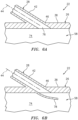
- the air conduit 42 and its first end 46 may be fluidly coupled with a flowpath 74 (e.g., a core gas path) within the compressor section 22 through a bleed aperture 76; e.g., orifice, through-hole, etc.
- the bleed aperture 76 of FIG. 6A is disposed in and extends through the case structure 26 and its outer casing wall 38.
- the air conduit 42 and its first end 46 may be fluidly coupled with the flowpath 74 through an air scoop 78.
- the air scoop 78 of FIG. 6B is connected to the case structure 26 and its outer casing wall 38 and projects into the flowpath 74.
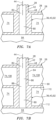
- the air conduit 42 and its second end 48 may be fluidly coupled with at least one internal passage 80 of the stator vane array 40 (e.g., directly) through an aperture 82 in the case structure 26 / the outer casing wall 38.
- the air conduit 42 and its second end 48 may be fluidly coupled with the at least one internal passage 80 of the stator vane array 40 (e.g., indirectly) through at least one intermediate structure 84 and/or another portion of the case structure 26 (or another structure).
- the air conduit 42 may be fluidly coupled, in serial, with the aperture 82 in the outer casing wall 38, at least one internal passage 86 of the intermediate structure 84, an aperture 88 in an inner casing wall 90 of the case structure 26, and the at least one internal passage 80 of the stator vane array 40.
- the intermediate structure 84 may be an internal air conduit exposed to the flowpath 74.
- This internal air conduit may have a similar geometry to the external air conduit 42.
- the internal air conduit may have a cross-sectional geometry with an airfoil shape or another aerodynamic shape.
- the internal air conduit may extend radially across (e.g., a diffuser portion of) the flowpath 74 between and to the casing walls 38 and 90.
- the intermediate structure 84 may be another stator vane array (e.g., a diffuser vane array) or a stator vane thereof with one or more internal passages (e.g., 80, 80A, 80B, 80C, 86).
- a stator vane array e.g., a diffuser vane array
- a stator vane thereof with one or more internal passages e.g. 80, 80A, 80B, 80C, 86.
- the stator vane array 40 includes a plurality of stator vanes 92; e.g., turbine vanes. These stator vanes 92 are arranged circumferentially about the centerline axis 30 in an annular array. At least one (or only one) of the stator vanes 92 is hollow and fluidly coupled with / receives the cooling air from the air conduit 42.
- the at least one stator vane 92 may be configured with a single internal passage 80 fluidly coupled with and downstream of the air conduit 42 (see FIG. 8 ).
- the at least one stator vane 92 may be configured with a plurality of (e.g., parallel) internal passages 80A, 80B and 80C (generally referred to as "80") (e.g., branches, capillaries, etc.) fluidly coupled with and downstream of the air conduit 42 (see FIG. 8 ).
- the internal passage(s) 80 in the at least one stator vane 92 may be configured to provide the cooling air to another downstream volume 94 (see FIGS. 7A and 7B ); e.g., a cavity or passage.
- Each internal passage 80 for example, may extend radially through (or out of) the respective stator vane 92.
- the present disclosure is not limited to the above exemplary internal passage configurations.
- the turbine engine 20 may include a single air conduit 42 external to the case structure 26 and its outer casing wall 38.
- This single air conduit 42 may service a single one of the stator vanes 92 (e.g., see FIG. 8 ), some of the stator vanes 92 (see FIG. 10 ) or each of the stator vanes 92.
- each stator vane 92, or a subset (e.g., every other one) of the stator vanes 92 may be configured with its own respective air conduit 42.
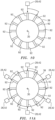
- the cooling system 28 includes a plurality of the air conduits 42 external to the case structure 26.
- Each of these air conduits 42 is respectively fluidly coupled with a respective one of the stator vanes 92 in the stator vane array 40.
- a subset of the stator vanes 92 in the stator vane array 40 are cooled by air from the respective air conduits 42.
- each of the stator vanes 92 in the stator vane array 40 is cooled by air from a respective one of the air conduits 42.
- the turbine engine 20 may include a plurality of the air conduits 42, where each air conduit 42 may service multiple stator vanes 92 (e.g., see optional dashed lines in FIG. 11A ).
- the present disclosure is not limited to the foregoing exemplary pairings / configurations of air conduits 42 and stator vanes 92.
- the case structure 26 may include a plurality of walls.
- the case structure 26 of FIG. 12 includes a compressor wall 96 (e.g., a forward portion of the outer casing wall 38), a diffuser wall 97 (e.g., an aft portion of the outer casing wall 38), an outer combustor wall 98 of a (e.g., annular) combustor 104, an inner combustor wall 99 of the combustor 104, a bulkhead wall 100 of the combustor 104, an outer turbine wall 101 and an inner turbine wall 102.
- a compressor wall 96 e.g., a forward portion of the outer casing wall 38
- a diffuser wall 97 e.g., an aft portion of the outer casing wall 38
- an outer combustor wall 98 of a (e.g., annular) combustor 104 e.g., annular) combustor 104
- the compressor wall 96 extends axially along the centerline axis 30 between and is connected to an inlet section 105 of the turbine engine 20 and the diffuser wall 97.
- the compressor wall 96 of FIG. 12 circumscribes, axially overlaps and thereby houses a rotor 106 of the compressor section 22.
- the diffuser wall 97 extends axially along the centerline axis 30 between and is connected to the compressor wall 96 and an aft end portion of the inner turbine wall 102.
- the diffuser wall 97 is spaced / displaced radially outboard from and axially overlaps the combustor 104.
- the diffuser wall 97 of FIG. 12 thereby forms an outer peripheral boundary of a diffuser plenum 108 that surrounds the combustor 104.
- the outer combustor wall 98 extends axially along the centerline axis 30 between and may be connected to the bulkhead wall 100 and an outer platform 110 of the stator vane array 40.
- the inner combustor wall 99 is circumscribed and axially overlapped by the outer combustor wall 98.
- the inner combustor wall 99 extends axially along the centerline axis 30 between and may be connected to the bulkhead wall 100 and an inner platform 112 of the stator vane array 40.
- the bulkhead wall 100 extends radially between and is connected to aft end portions of the outer combustor wall 98 and the inner combustor wall 99.
- the case walls 98-100 may thereby collectively form peripheral boundaries of a (e.g., annular) combustion chamber 114 therebetween.
- the outer turbine wall 101 may be connected to the stator vane array platform 110.
- the outer turbine wall 101 projects axially out from the stator vane array platform 110 and extends axially towards / to an aft, downstream end of an inner platform 116 of the compressor rotor 106.
- This outer turbine wall 101 is circumscribed and axially overlapped by the diffuser wall 97.
- the outer turbine wall 101 of FIG. 12 may thereby form an inner peripheral boundary of the flowpath 74 within a diffuser 118 of the turbine engine 20, and may form an outer peripheral boundary of the flowpath 74 within a (e.g., upstream) portion of the turbine section 24.
- the outer turbine wall 101 of FIG. 12 also circumscribes, axially overlaps and thereby houses a (e.g., upstream) portion of a rotor 120 of the turbine section 24.
- the inner turbine wall 102 may be connected to the stator vane array platform 112. An upstream portion of the inner turbine wall 102 projects axially (in an aft-to-forward direction) out from the stator vane array platform 112 to a turning portion of the inner turbine wall 102. A downstream portion of the inner turbine wall 102 projects axially (in a forward-to-aft direction) away from the inner turbine wall turning portion to an outlet of the turbine section 24 at the case second end 34.
- the inner turbine wall 102 is circumscribed and axially overlapped by the combustor 104.
- the inner turbine wall 102 is also spaced / displaced radially inboard from the combustor 104.
- the inner turbine wall 102 forms an outer peripheral boundary of the core flowpath 74 within a (e.g., downstream) portion of the turbine section 24.
- the inner turbine wall 102 of FIG. 12 also circumscribes, axially overlaps and thereby houses a (e.g., downstream) portion of the turbine rotor 120.
- the case structure 26 may also include one or more internal support structures with one or more support members. Examples of support members include, but are not limited to, struts, structural guide vanes, bearing supports, bearing compartment walls, etc.
- the case structure 26 of FIG. 12 includes a forward support structure 122, an aft support structure 124, an inlet nozzle 126 and the stator vane array 40.
- the forward support structure 122 may be configured to support a shaft bearing 128.
- the aft support structure 124 may be configured to support another shaft bearing 130.
- the inlet nozzle 126 may be configured to condition core air entering the compressor section 22.
- the inlet nozzle 126 for example, may include one or more guide vanes 132 which impart swirl to the core air.
- the stator vane array 40 may similarly be configured to condition the combustion products exiting the combustor section 23.
- the stator vanes 92 may import swirl to the combustion products, where these stator vanes 92 are connected to and extend radially between the stator vane array inner and outer platforms 112 and 110.
- the case structure 26, of course, may also or alternative include various other static / stationary gas turbine engine components.
- cooling air provided to the stator vane(s) 92 may also be provided to cool the stator vane array inner platform 112 and/or a forward / downstream portion of the inner combustor wall 99 before flowing into the combustion chamber 114.
- Some or all stationary components (e.g., 26, 42 and 84) of the turbine engine 20 is formed (e.g., additively manufactured) together as a single monolithic body.
- monolithic describes an apparatus which is formed as a single unitary body.
- the components (e.g., 26, 38, 42 and/or 92) in FIG. 7A or the components (e.g., 26, 38, 42, 84, 90, 92, 110 and/or 112) in FIG. 7B for example, are collectively additively manufactured, cast, machined and/or otherwise formed together as an integral, unitary body.
- the cooling system components e.g., the air conduits 42 and 84
- a non-monolithic body includes parts that are discretely formed from one another, where those parts are subsequently mechanically fastened and/or otherwise attached to one another.
- the cooling system 28 and its air conduit(s) 42 may be included in various turbine engines.
- the cooling system 28 and its air conduit(s) 42 may be included in a geared turbine engine where a gear train connects one or more shafts to one or more rotors in a fan section, a compressor section and/or any other engine section.
- the cooling system 28 and its air conduit(s) 42 may be included in a turbine engine configured without a gear train.
- the cooling system 28 and its air conduit(s) 42 may be included in a geared or non-geared turbine engine configured with a single spool (see FIG. 12 ), with two spools, or with more than two spools.
- the turbine engine may be configured as a turbofan engine, a turbojet engine, a propfan engine, a pusher fan engine or any other type of turbine engine. The present disclosure therefore is not limited to any particular types or configurations of turbine engines.
Landscapes
- Engineering & Computer Science (AREA)
- Mechanical Engineering (AREA)
- General Engineering & Computer Science (AREA)
- Chemical & Material Sciences (AREA)
- Combustion & Propulsion (AREA)
- Physics & Mathematics (AREA)
- Fluid Mechanics (AREA)
- Turbine Rotor Nozzle Sealing (AREA)
- Structures Of Non-Positive Displacement Pumps (AREA)
Claims (15)
- Baugruppe für ein Turbinentriebwerk, umfassend:eine Gehäusekonstruktion (26), die sich kreisförmig um eine und axial entlang einer Achse (30) erstreckt; undeine Luftleitung (42), die eine Leitungsmittellinie (44), ein erstes Leitungsende (46) und ein zweites Leitungsende (48) aufweist, wobei sich die Luftleitung in Längsrichtung zwischen dem ersten Leitungsende (46) und dem zweiten Leitungsende (48) entlang der Leitungsmittellinie (44) erstreckt, das erste Leitungsende (46) an einer ersten Stelle mit der Gehäusekonstruktion (26) verbunden ist, das zweite Leitungsende (48) an einer zweiten Stelle mit der Gehäusekonstruktion (26) verbunden ist, die Luftleitung (42) zwischen dem ersten Leitungsende (26) und dem zweiten Leitungsende (48) in Längsrichtung von der Gehäusekonstruktion (26) versetzt ist und mindestens ein Großteil der Leitungsmittellinie (44) einer nicht geraden Bahn folgt;dadurch gekennzeichnet, dass die Gehäusekonstruktion (26) und die Luftleitung (42) zusammen als monolithischer Körper ausgebildet sind.
- Baugruppe nach Anspruch 1, wobei die nicht gerade Bahn eine kontinuierlich gekrümmte Bahn ist.
- Baugruppe nach Anspruch 1 oder 2, wobei die gesamte Leitungsmittellinie (44) der nicht geraden Bahn folgt.
- Baugruppe nach einem der vorhergehenden Ansprüche, wobei:die Leitungsmittellinie (44) an dem ersten Leitungsende (46) um einen ersten eingeschlossenen Winkel (64) von der Gehäusekonstruktion (26) winkelversetzt ist; unddie Leitungsmittellinie (44) an dem zweiten Leitungsende (48) um einen zweiten eingeschlossenen Winkel (66), der sich von dem ersten eingeschlossenen Winkel (64) unterscheidet, von der Gehäusekonstruktion (26) winkelversetzt ist.
- Baugruppe nach einem der vorhergehenden Ansprüche, wobei:die erste Stelle axial entlang der Achse (30) von der zweiten Stelle versetzt ist; und/oderdie erste Stelle in Umfangsrichtung um die Achse (30) von der zweiten Stelle versetzt ist.
- Baugruppe nach einem der vorhergehenden Ansprüche, wobei mindestens ein Teil der Luftleitung (42) eine polygonale Querschnittsgeometrie aufweist.
- Baugruppe nach einem der vorhergehenden Ansprüche, wobei mindestens ein Teil der Luftleitung (42) eine langgestreckte Querschnittsgeometrie aufweist.
- Baugruppe nach einem der vorhergehenden Ansprüche, ferner umfassend:eine Luftquelle (58); undeine luftgekühlte Komponente (36) innerhalb der Gehäusekonstruktion (26);wobei die Luftleitung (42) zum Empfangen von Luft von der Luftquelle (58) und Leiten der empfangenen Luft an die luftgekühlte Komponente (36) konfiguriert ist.
- Baugruppe nach einem der vorhergehenden Ansprüche, wobei die Luftquelle (58) einen Verdichterabschnitt (22) eines Turbinentriebwerks umfasst.
- Baugruppe nach einem der vorhergehenden Ansprüche, wobei die luftgekühlte Komponente (36) eine Turbinenleitschaufel (92) umfasst.
- Baugruppe nach einem der vorhergehenden Ansprüche, ferner umfassend:eine Statorleitschaufel (92) mit einem oder mehreren Innendurchgängen (80);wobei die Luftleitung (42) fluidisch an den einen oder die mehreren Innendurchgänge (80) gekoppelt ist.
- Baugruppe nach einem der vorhergehenden Ansprüche, ferner umfassend:eine zweite Luftleitung (84) innerhalb der Gehäusekonstruktion (26) ;wobei sich die zweite Luftleitung (84) radial über einen Strömungsweg (74) eines oder des Turbinentriebwerks erstreckt; undwobei die zweite Luftleitung (84) fluidisch an die Luftleitung (42) gekoppelt ist und sich stromabwärts davon befindet.
- Baugruppe nach einem der vorhergehenden Ansprüche, wobei die Luftleitung (42) an dem ersten Leitungsende (46) fluidisch an eine Entlüftungsöffnung (76) in der Gehäusekonstruktion (26) gekoppelt ist.
- Baugruppe nach einem der vorhergehenden Ansprüche, ferner umfassend:einen mit der Gehäusekonstruktion (26) verbundenen Schöpfer (78) ;wobei der Schöpfer (78) in einen oder den Strömungsweg (74) eines oder des Turbinentriebwerks ragt; undwobei die Luftleitung (42) fluidisch an den Schöpfer (78) gekoppelt ist und sich stromabwärts davon befindet.
- Baugruppe nach einem vorhergehenden Anspruch, wobeidas erste Leitungsende (46) ein stromaufwärts gelegenes Ende der Luftleitung (42) ist;das zweite Leitungsende (48) ein stromabwärts gelegenes Ende der Luftleitung (42) ist; undeine maximale Versetzung (62) zwischen der Gehäusekonstruktion (26) und der Luftleitung (42) in Längsrichtung entlang der Leitungsmittellinie (44) näher an dem zweiten Leitungsende (48) liegt als an dem ersten Leitungsende (46).
Priority Applications (1)
| Application Number | Priority Date | Filing Date | Title |
|---|---|---|---|
| EP24212756.1A EP4524371A1 (de) | 2021-03-31 | 2022-03-28 | Turbinenmotor mit ringförmiger luftleitung |
Applications Claiming Priority (1)
| Application Number | Priority Date | Filing Date | Title |
|---|---|---|---|
| US17/219,207 US11732656B2 (en) | 2021-03-31 | 2021-03-31 | Turbine engine with soaring air conduit |
Related Child Applications (1)
| Application Number | Title | Priority Date | Filing Date |
|---|---|---|---|
| EP24212756.1A Division EP4524371A1 (de) | 2021-03-31 | 2022-03-28 | Turbinenmotor mit ringförmiger luftleitung |
Publications (2)
| Publication Number | Publication Date |
|---|---|
| EP4067623A1 EP4067623A1 (de) | 2022-10-05 |
| EP4067623B1 true EP4067623B1 (de) | 2024-11-20 |
Family
ID=80978885
Family Applications (2)
| Application Number | Title | Priority Date | Filing Date |
|---|---|---|---|
| EP22164811.6A Active EP4067623B1 (de) | 2021-03-31 | 2022-03-28 | Turbinentriebwerk mit kühlluftleitung |
| EP24212756.1A Pending EP4524371A1 (de) | 2021-03-31 | 2022-03-28 | Turbinenmotor mit ringförmiger luftleitung |
Family Applications After (1)
| Application Number | Title | Priority Date | Filing Date |
|---|---|---|---|
| EP24212756.1A Pending EP4524371A1 (de) | 2021-03-31 | 2022-03-28 | Turbinenmotor mit ringförmiger luftleitung |
Country Status (2)
| Country | Link |
|---|---|
| US (1) | US11732656B2 (de) |
| EP (2) | EP4067623B1 (de) |
Families Citing this family (6)
| Publication number | Priority date | Publication date | Assignee | Title |
|---|---|---|---|---|
| US12523156B2 (en) * | 2023-05-23 | 2026-01-13 | Rtx Corporation | Turbine engine structure with an integral fluid reservoir |
| US12486774B2 (en) * | 2023-12-22 | 2025-12-02 | Rtx Corporation | Cooling nozzle vanes of a turbine engine |
| US12215604B1 (en) * | 2023-12-22 | 2025-02-04 | Rtx Corporation | Cooling nozzle vanes of a turbine engine |
| US12546227B2 (en) * | 2024-02-09 | 2026-02-10 | Rtx Corporation | Cooling nozzle vanes of a turbine engine |
| US20260015946A1 (en) * | 2024-07-11 | 2026-01-15 | Pratt & Whitney Canada Corp. | Service tube assembly for turbine engine |
| US20260085836A1 (en) * | 2024-09-20 | 2026-03-26 | Rtx Corporation | Flow Assisted Integral Splash Plate |
Family Cites Families (34)
| Publication number | Priority date | Publication date | Assignee | Title |
|---|---|---|---|---|
| DE2042478C3 (de) * | 1970-08-27 | 1975-08-14 | Motoren- Und Turbinen-Union Muenchen Gmbh, 8000 Muenchen | Gasturbinentriebwerk, vorzugsweise Strahltriebwerk für Flugzeuge, mit Kühlluft- und gegebenenfalls Sperrluftentnahme |
| US4157010A (en) * | 1977-06-03 | 1979-06-05 | General Electric Company | Gas turbine engine with power modulation capability |
| US4576547A (en) * | 1983-11-03 | 1986-03-18 | United Technologies Corporation | Active clearance control |
| US5048288A (en) * | 1988-12-20 | 1991-09-17 | United Technologies Corporation | Combined turbine stator cooling and turbine tip clearance control |
| US5134844A (en) | 1990-07-30 | 1992-08-04 | General Electric Company | Aft entry cooling system and method for an aircraft engine |
| US5394687A (en) * | 1993-12-03 | 1995-03-07 | The United States Of America As Represented By The Department Of Energy | Gas turbine vane cooling system |
| DE102004030597A1 (de) * | 2004-06-24 | 2006-01-26 | Rolls-Royce Deutschland Ltd & Co Kg | Strömungsarbeitsmaschine mit Aussenradstrahlerzeugung am Stator |
| US7568343B2 (en) | 2005-09-12 | 2009-08-04 | Florida Turbine Technologies, Inc. | Small gas turbine engine with multiple burn zones |
| US7669425B2 (en) * | 2006-10-25 | 2010-03-02 | Siemens Energy, Inc. | Closed loop turbine cooling fluid reuse system for a turbine engine |
| US8495883B2 (en) * | 2007-04-05 | 2013-07-30 | Siemens Energy, Inc. | Cooling of turbine components using combustor shell air |
| US8240979B2 (en) | 2007-10-24 | 2012-08-14 | United Technologies Corp. | Gas turbine engine systems involving integrated fluid conduits |
| GB201015028D0 (en) * | 2010-09-10 | 2010-10-20 | Rolls Royce Plc | Gas turbine engine |
| US9003807B2 (en) * | 2011-11-08 | 2015-04-14 | Siemens Aktiengesellschaft | Gas turbine engine with structure for directing compressed air on a blade ring |
| US9562475B2 (en) * | 2012-12-19 | 2017-02-07 | Siemens Aktiengesellschaft | Vane carrier temperature control system in a gas turbine engine |
| US9714611B2 (en) | 2013-02-15 | 2017-07-25 | Siemens Energy, Inc. | Heat shield manifold system for a midframe case of a gas turbine engine |
| EP3093432B1 (de) * | 2015-05-15 | 2021-04-21 | Ansaldo Energia Switzerland AG | Verfahren zur kühlung einer gasturbine sowie gasturbine zur durchführung des verfahrens |
| US10024538B2 (en) * | 2015-08-26 | 2018-07-17 | United Technologies Corporation | Apparatus and method for air extraction at a gas turbine engine combustor |
| US10227930B2 (en) * | 2016-03-28 | 2019-03-12 | General Electric Company | Compressor bleed systems in turbomachines and methods of extracting compressor airflow |
| US10739006B2 (en) * | 2017-03-15 | 2020-08-11 | General Electric Company | Fuel nozzle for a gas turbine engine |
| US10411756B2 (en) | 2017-04-06 | 2019-09-10 | United Technologies Corporation | Wave guide with fluid passages |
| US10948108B2 (en) | 2017-05-02 | 2021-03-16 | Unison Industries, Llc | Turbine engine duct |
| FR3072127B1 (fr) * | 2017-10-05 | 2019-11-01 | Safran Aircraft Engines | Conduit de decharge d'un moyeu de carter intermediaire pour turboreacteur d'aeronef comportant des canaux de refroidissement |
| GB201801956D0 (en) * | 2018-02-07 | 2018-03-21 | Rolls Royce Plc | Tail bearing housing |
| DE102018112244A1 (de) * | 2018-05-22 | 2019-11-28 | Rolls-Royce Deutschland Ltd & Co Kg | Gasturbinentriebwerk |
| US10954865B2 (en) * | 2018-06-19 | 2021-03-23 | The Boeing Company | Pressurized air systems for aircraft and related methods |
| US20200011455A1 (en) * | 2018-07-05 | 2020-01-09 | Unison Industries, Llc | Duct assembly and method of forming |
| US11530650B2 (en) * | 2018-07-13 | 2022-12-20 | Raytheon Technologies Corporation | Gas turbine engine with active variable turbine cooling |
| US11125187B2 (en) * | 2018-08-01 | 2021-09-21 | Raytheon Technologies Corporation | Turbomachinery transition duct for wide bypass ratio ranges |
| US11156156B2 (en) | 2018-10-04 | 2021-10-26 | Raytheon Technologies Corporation | Gas turbine engine with a unitary structure and method for manufacturing the same |
| US11994034B2 (en) * | 2018-10-11 | 2024-05-28 | Pratt & Whitney Canada Corp. | Gas turbine engine with low pressure compressor stages |
| US20200141327A1 (en) * | 2018-11-02 | 2020-05-07 | Pratt & Whitney Canada Corp. | Auxiliary power unit |
| US11300002B2 (en) * | 2018-12-07 | 2022-04-12 | Pratt & Whitney Canada Corp. | Static take-off port |
| FR3092135B1 (fr) * | 2019-01-29 | 2021-10-01 | Safran Aircraft Engines | Turbomachine, telle qu’un turboreacteur d’avion |
| US11021963B2 (en) | 2019-05-03 | 2021-06-01 | Raytheon Technologies Corporation | Monolithic body including an internal passage with a generally teardrop shaped cross-sectional geometry |
-
2021
- 2021-03-31 US US17/219,207 patent/US11732656B2/en active Active
-
2022
- 2022-03-28 EP EP22164811.6A patent/EP4067623B1/de active Active
- 2022-03-28 EP EP24212756.1A patent/EP4524371A1/de active Pending
Also Published As
| Publication number | Publication date |
|---|---|
| EP4067623A1 (de) | 2022-10-05 |
| EP4524371A1 (de) | 2025-03-19 |
| US20220316408A1 (en) | 2022-10-06 |
| US11732656B2 (en) | 2023-08-22 |
Similar Documents
| Publication | Publication Date | Title |
|---|---|---|
| EP4067623B1 (de) | Turbinentriebwerk mit kühlluftleitung | |
| US10739002B2 (en) | Fluidic nozzle assembly for a turbine engine | |
| US10583933B2 (en) | Method and apparatus for undercowl flow diversion cooling | |
| EP3845748B1 (de) | Turbinentriebwerksystem mit wärmetauscher im umgehbarem nebenkanal | |
| US10823422B2 (en) | Tangential bulk swirl air in a trapped vortex combustor for a gas turbine engine | |
| EP3058176B1 (de) | Gasturbinentriebwerk mit verdichterplattendeflektoren | |
| CN114991961B (zh) | 多流体热交换器 | |
| EP2900968B1 (de) | Strömungsmessendes t-rohr mit geteilter zone | |
| US20170198602A1 (en) | Gas turbine engine with a cooled nozzle segment | |
| US20180328177A1 (en) | Gas turbine engine with a cooled compressor | |
| EP3650655A1 (de) | Schaufelprofil, zugehöriges gasturbinentriebwerk und montageverfahren | |
| EP4582673A1 (de) | Kühldüsenschaufeln eines turbinenmotors | |
| EP4343134A2 (de) | Gasturbinenmotor mit integriertem bypasskanal | |
| US11873758B1 (en) | Gas turbine engine component with integral heat exchanger | |
| EP3450686B1 (de) | Turbinenschaufel-cluster mit verbesserter plattformkühlung | |
| EP3650646A1 (de) | Schaufel mit prallbrause und kühlkanalnetz mit hinterem einlass | |
| EP4230841A1 (de) | Verdichter-turbine-drehanordnung mit integriertem kühlkreislauf/integrierten kühlkreis(en) | |
| US11028700B2 (en) | Airfoil with cooling passage circuit through platforms and airfoil section | |
| EP3556997B1 (de) | Schaufel mit einlassöffnung an der hinteren seite der wurzel | |
| EP3450697B1 (de) | Leitschaufelsegment und zugehöriges gasturbinentriebwerk | |
| EP2977557B1 (de) | Gekühlte schaufelstruktur und zugehöriges kühlverfahren | |
| EP4560113A1 (de) | Kühldüsenschaufeln eines turbinenmotors | |
| US12523156B2 (en) | Turbine engine structure with an integral fluid reservoir | |
| US12152506B2 (en) | Bleed passage arrangement for a gas turbine engine shroud | |
| EP4685341A1 (de) | Diffusorturbinenströmungsnetzwerk |
Legal Events
| Date | Code | Title | Description |
|---|---|---|---|
| PUAI | Public reference made under article 153(3) epc to a published international application that has entered the european phase |
Free format text: ORIGINAL CODE: 0009012 |
|
| STAA | Information on the status of an ep patent application or granted ep patent |
Free format text: STATUS: THE APPLICATION HAS BEEN PUBLISHED |
|
| AK | Designated contracting states |
Kind code of ref document: A1 Designated state(s): AL AT BE BG CH CY CZ DE DK EE ES FI FR GB GR HR HU IE IS IT LI LT LU LV MC MK MT NL NO PL PT RO RS SE SI SK SM TR |
|
| STAA | Information on the status of an ep patent application or granted ep patent |
Free format text: STATUS: REQUEST FOR EXAMINATION WAS MADE |
|
| 17P | Request for examination filed |
Effective date: 20230405 |
|
| RBV | Designated contracting states (corrected) |
Designated state(s): AL AT BE BG CH CY CZ DE DK EE ES FI FR GB GR HR HU IE IS IT LI LT LU LV MC MK MT NL NO PL PT RO RS SE SI SK SM TR |
|
| RAP3 | Party data changed (applicant data changed or rights of an application transferred) |
Owner name: RTX CORPORATION |
|
| GRAP | Despatch of communication of intention to grant a patent |
Free format text: ORIGINAL CODE: EPIDOSNIGR1 |
|
| STAA | Information on the status of an ep patent application or granted ep patent |
Free format text: STATUS: GRANT OF PATENT IS INTENDED |
|
| RIC1 | Information provided on ipc code assigned before grant |
Ipc: F02C 7/18 20060101ALI20240523BHEP Ipc: F02C 6/08 20060101ALI20240523BHEP Ipc: F01D 9/06 20060101AFI20240523BHEP |
|
| INTG | Intention to grant announced |
Effective date: 20240620 |
|
| GRAS | Grant fee paid |
Free format text: ORIGINAL CODE: EPIDOSNIGR3 |
|
| GRAA | (expected) grant |
Free format text: ORIGINAL CODE: 0009210 |
|
| STAA | Information on the status of an ep patent application or granted ep patent |
Free format text: STATUS: THE PATENT HAS BEEN GRANTED |
|
| AK | Designated contracting states |
Kind code of ref document: B1 Designated state(s): AL AT BE BG CH CY CZ DE DK EE ES FI FR GB GR HR HU IE IS IT LI LT LU LV MC MK MT NL NO PL PT RO RS SE SI SK SM TR |
|
| REG | Reference to a national code |
Ref country code: GB Ref legal event code: FG4D |
|
| REG | Reference to a national code |
Ref country code: CH Ref legal event code: EP |
|
| REG | Reference to a national code |
Ref country code: DE Ref legal event code: R096 Ref document number: 602022007796 Country of ref document: DE |
|
| REG | Reference to a national code |
Ref country code: IE Ref legal event code: FG4D |
|
| REG | Reference to a national code |
Ref country code: LT Ref legal event code: MG9D |
|
| REG | Reference to a national code |
Ref country code: NL Ref legal event code: MP Effective date: 20241120 |
|
| PG25 | Lapsed in a contracting state [announced via postgrant information from national office to epo] |
Ref country code: HR Free format text: LAPSE BECAUSE OF FAILURE TO SUBMIT A TRANSLATION OF THE DESCRIPTION OR TO PAY THE FEE WITHIN THE PRESCRIBED TIME-LIMIT Effective date: 20241120 Ref country code: IS Free format text: LAPSE BECAUSE OF FAILURE TO SUBMIT A TRANSLATION OF THE DESCRIPTION OR TO PAY THE FEE WITHIN THE PRESCRIBED TIME-LIMIT Effective date: 20250320 Ref country code: PT Free format text: LAPSE BECAUSE OF FAILURE TO SUBMIT A TRANSLATION OF THE DESCRIPTION OR TO PAY THE FEE WITHIN THE PRESCRIBED TIME-LIMIT Effective date: 20250320 |
|
| PG25 | Lapsed in a contracting state [announced via postgrant information from national office to epo] |
Ref country code: FI Free format text: LAPSE BECAUSE OF FAILURE TO SUBMIT A TRANSLATION OF THE DESCRIPTION OR TO PAY THE FEE WITHIN THE PRESCRIBED TIME-LIMIT Effective date: 20241120 Ref country code: NL Free format text: LAPSE BECAUSE OF FAILURE TO SUBMIT A TRANSLATION OF THE DESCRIPTION OR TO PAY THE FEE WITHIN THE PRESCRIBED TIME-LIMIT Effective date: 20241120 |
|
| REG | Reference to a national code |
Ref country code: AT Ref legal event code: MK05 Ref document number: 1743747 Country of ref document: AT Kind code of ref document: T Effective date: 20241120 |
|
| PG25 | Lapsed in a contracting state [announced via postgrant information from national office to epo] |
Ref country code: BG Free format text: LAPSE BECAUSE OF FAILURE TO SUBMIT A TRANSLATION OF THE DESCRIPTION OR TO PAY THE FEE WITHIN THE PRESCRIBED TIME-LIMIT Effective date: 20241120 |
|
| PG25 | Lapsed in a contracting state [announced via postgrant information from national office to epo] |
Ref country code: ES Free format text: LAPSE BECAUSE OF FAILURE TO SUBMIT A TRANSLATION OF THE DESCRIPTION OR TO PAY THE FEE WITHIN THE PRESCRIBED TIME-LIMIT Effective date: 20241120 |
|
| PG25 | Lapsed in a contracting state [announced via postgrant information from national office to epo] |
Ref country code: NO Free format text: LAPSE BECAUSE OF FAILURE TO SUBMIT A TRANSLATION OF THE DESCRIPTION OR TO PAY THE FEE WITHIN THE PRESCRIBED TIME-LIMIT Effective date: 20250220 |
|
| PG25 | Lapsed in a contracting state [announced via postgrant information from national office to epo] |
Ref country code: AT Free format text: LAPSE BECAUSE OF FAILURE TO SUBMIT A TRANSLATION OF THE DESCRIPTION OR TO PAY THE FEE WITHIN THE PRESCRIBED TIME-LIMIT Effective date: 20241120 Ref country code: LV Free format text: LAPSE BECAUSE OF FAILURE TO SUBMIT A TRANSLATION OF THE DESCRIPTION OR TO PAY THE FEE WITHIN THE PRESCRIBED TIME-LIMIT Effective date: 20241120 Ref country code: GR Free format text: LAPSE BECAUSE OF FAILURE TO SUBMIT A TRANSLATION OF THE DESCRIPTION OR TO PAY THE FEE WITHIN THE PRESCRIBED TIME-LIMIT Effective date: 20250221 |
|
| PG25 | Lapsed in a contracting state [announced via postgrant information from national office to epo] |
Ref country code: PL Free format text: LAPSE BECAUSE OF FAILURE TO SUBMIT A TRANSLATION OF THE DESCRIPTION OR TO PAY THE FEE WITHIN THE PRESCRIBED TIME-LIMIT Effective date: 20241120 |
|
| PG25 | Lapsed in a contracting state [announced via postgrant information from national office to epo] |
Ref country code: RS Free format text: LAPSE BECAUSE OF FAILURE TO SUBMIT A TRANSLATION OF THE DESCRIPTION OR TO PAY THE FEE WITHIN THE PRESCRIBED TIME-LIMIT Effective date: 20250220 |
|
| PG25 | Lapsed in a contracting state [announced via postgrant information from national office to epo] |
Ref country code: SM Free format text: LAPSE BECAUSE OF FAILURE TO SUBMIT A TRANSLATION OF THE DESCRIPTION OR TO PAY THE FEE WITHIN THE PRESCRIBED TIME-LIMIT Effective date: 20241120 |
|
| PG25 | Lapsed in a contracting state [announced via postgrant information from national office to epo] |
Ref country code: DK Free format text: LAPSE BECAUSE OF FAILURE TO SUBMIT A TRANSLATION OF THE DESCRIPTION OR TO PAY THE FEE WITHIN THE PRESCRIBED TIME-LIMIT Effective date: 20241120 |
|
| PG25 | Lapsed in a contracting state [announced via postgrant information from national office to epo] |
Ref country code: EE Free format text: LAPSE BECAUSE OF FAILURE TO SUBMIT A TRANSLATION OF THE DESCRIPTION OR TO PAY THE FEE WITHIN THE PRESCRIBED TIME-LIMIT Effective date: 20241120 |
|
| PG25 | Lapsed in a contracting state [announced via postgrant information from national office to epo] |
Ref country code: RO Free format text: LAPSE BECAUSE OF FAILURE TO SUBMIT A TRANSLATION OF THE DESCRIPTION OR TO PAY THE FEE WITHIN THE PRESCRIBED TIME-LIMIT Effective date: 20241120 |
|
| PG25 | Lapsed in a contracting state [announced via postgrant information from national office to epo] |
Ref country code: SK Free format text: LAPSE BECAUSE OF FAILURE TO SUBMIT A TRANSLATION OF THE DESCRIPTION OR TO PAY THE FEE WITHIN THE PRESCRIBED TIME-LIMIT Effective date: 20241120 |
|
| PG25 | Lapsed in a contracting state [announced via postgrant information from national office to epo] |
Ref country code: CZ Free format text: LAPSE BECAUSE OF FAILURE TO SUBMIT A TRANSLATION OF THE DESCRIPTION OR TO PAY THE FEE WITHIN THE PRESCRIBED TIME-LIMIT Effective date: 20241120 |
|
| PG25 | Lapsed in a contracting state [announced via postgrant information from national office to epo] |
Ref country code: IT Free format text: LAPSE BECAUSE OF FAILURE TO SUBMIT A TRANSLATION OF THE DESCRIPTION OR TO PAY THE FEE WITHIN THE PRESCRIBED TIME-LIMIT Effective date: 20241120 |
|
| REG | Reference to a national code |
Ref country code: DE Ref legal event code: R097 Ref document number: 602022007796 Country of ref document: DE |
|
| PG25 | Lapsed in a contracting state [announced via postgrant information from national office to epo] |
Ref country code: SE Free format text: LAPSE BECAUSE OF FAILURE TO SUBMIT A TRANSLATION OF THE DESCRIPTION OR TO PAY THE FEE WITHIN THE PRESCRIBED TIME-LIMIT Effective date: 20241120 |
|
| PLBE | No opposition filed within time limit |
Free format text: ORIGINAL CODE: 0009261 |
|
| STAA | Information on the status of an ep patent application or granted ep patent |
Free format text: STATUS: NO OPPOSITION FILED WITHIN TIME LIMIT |
|
| PG25 | Lapsed in a contracting state [announced via postgrant information from national office to epo] |
Ref country code: MC Free format text: LAPSE BECAUSE OF FAILURE TO SUBMIT A TRANSLATION OF THE DESCRIPTION OR TO PAY THE FEE WITHIN THE PRESCRIBED TIME-LIMIT Effective date: 20241120 |
|
| 26N | No opposition filed |
Effective date: 20250821 |
|
| REG | Reference to a national code |
Ref country code: CH Ref legal event code: H13 Free format text: ST27 STATUS EVENT CODE: U-0-0-H10-H13 (AS PROVIDED BY THE NATIONAL OFFICE) Effective date: 20251023 |
|
| PG25 | Lapsed in a contracting state [announced via postgrant information from national office to epo] |
Ref country code: LU Free format text: LAPSE BECAUSE OF NON-PAYMENT OF DUE FEES Effective date: 20250328 |
|
| REG | Reference to a national code |
Ref country code: BE Ref legal event code: MM Effective date: 20250331 |
|
| PG25 | Lapsed in a contracting state [announced via postgrant information from national office to epo] |
Ref country code: BE Free format text: LAPSE BECAUSE OF NON-PAYMENT OF DUE FEES Effective date: 20250331 |
|
| PG25 | Lapsed in a contracting state [announced via postgrant information from national office to epo] |
Ref country code: CH Free format text: LAPSE BECAUSE OF NON-PAYMENT OF DUE FEES Effective date: 20250331 |
|
| PG25 | Lapsed in a contracting state [announced via postgrant information from national office to epo] |
Ref country code: IE Free format text: LAPSE BECAUSE OF NON-PAYMENT OF DUE FEES Effective date: 20250328 |
|
| PGFP | Annual fee paid to national office [announced via postgrant information from national office to epo] |
Ref country code: GB Payment date: 20260220 Year of fee payment: 5 |
|
| PGFP | Annual fee paid to national office [announced via postgrant information from national office to epo] |
Ref country code: DE Payment date: 20260219 Year of fee payment: 5 |
|
| PGFP | Annual fee paid to national office [announced via postgrant information from national office to epo] |
Ref country code: FR Payment date: 20260219 Year of fee payment: 5 |