EP4067635B1 - Betrieb eines turbopropmotors für einen neustart während des flugs - Google Patents
Betrieb eines turbopropmotors für einen neustart während des flugs Download PDFInfo
- Publication number
- EP4067635B1 EP4067635B1 EP22166404.8A EP22166404A EP4067635B1 EP 4067635 B1 EP4067635 B1 EP 4067635B1 EP 22166404 A EP22166404 A EP 22166404A EP 4067635 B1 EP4067635 B1 EP 4067635B1
- Authority
- EP
- European Patent Office
- Prior art keywords
- propeller
- inflight
- engine
- restart
- detecting
- Prior art date
- Legal status (The legal status is an assumption and is not a legal conclusion. Google has not performed a legal analysis and makes no representation as to the accuracy of the status listed.)
- Active
Links
Images




Classifications
-
- F—MECHANICAL ENGINEERING; LIGHTING; HEATING; WEAPONS; BLASTING
- F02—COMBUSTION ENGINES; HOT-GAS OR COMBUSTION-PRODUCT ENGINE PLANTS
- F02C—GAS-TURBINE PLANTS; AIR INTAKES FOR JET-PROPULSION PLANTS; CONTROLLING FUEL SUPPLY IN AIR-BREATHING JET-PROPULSION PLANTS
- F02C9/00—Controlling gas-turbine plants; Controlling fuel supply in air- breathing jet-propulsion plants
-
- F—MECHANICAL ENGINEERING; LIGHTING; HEATING; WEAPONS; BLASTING
- F02—COMBUSTION ENGINES; HOT-GAS OR COMBUSTION-PRODUCT ENGINE PLANTS
- F02C—GAS-TURBINE PLANTS; AIR INTAKES FOR JET-PROPULSION PLANTS; CONTROLLING FUEL SUPPLY IN AIR-BREATHING JET-PROPULSION PLANTS
- F02C9/00—Controlling gas-turbine plants; Controlling fuel supply in air- breathing jet-propulsion plants
- F02C9/16—Control of working fluid flow
-
- B—PERFORMING OPERATIONS; TRANSPORTING
- B64—AIRCRAFT; AVIATION; COSMONAUTICS
- B64C—AEROPLANES; HELICOPTERS
- B64C11/00—Propellers, e.g. of ducted type; Features common to propellers and rotors for rotorcraft
- B64C11/30—Blade pitch-changing mechanisms
-
- F—MECHANICAL ENGINEERING; LIGHTING; HEATING; WEAPONS; BLASTING
- F02—COMBUSTION ENGINES; HOT-GAS OR COMBUSTION-PRODUCT ENGINE PLANTS
- F02C—GAS-TURBINE PLANTS; AIR INTAKES FOR JET-PROPULSION PLANTS; CONTROLLING FUEL SUPPLY IN AIR-BREATHING JET-PROPULSION PLANTS
- F02C6/00—Plural gas-turbine plants; Combinations of gas-turbine plants with other apparatus; Adaptations of gas-turbine plants for special use
- F02C6/20—Adaptations of gas-turbine plants for driving vehicles
- F02C6/206—Adaptations of gas-turbine plants for driving vehicles the vehicles being airscrew driven
-
- F—MECHANICAL ENGINEERING; LIGHTING; HEATING; WEAPONS; BLASTING
- F02—COMBUSTION ENGINES; HOT-GAS OR COMBUSTION-PRODUCT ENGINE PLANTS
- F02C—GAS-TURBINE PLANTS; AIR INTAKES FOR JET-PROPULSION PLANTS; CONTROLLING FUEL SUPPLY IN AIR-BREATHING JET-PROPULSION PLANTS
- F02C7/00—Features, components parts, details or accessories, not provided for in, or of interest apart form groups F02C1/00 - F02C6/00; Air intakes for jet-propulsion plants
- F02C7/26—Starting; Ignition
-
- F—MECHANICAL ENGINEERING; LIGHTING; HEATING; WEAPONS; BLASTING
- F02—COMBUSTION ENGINES; HOT-GAS OR COMBUSTION-PRODUCT ENGINE PLANTS
- F02C—GAS-TURBINE PLANTS; AIR INTAKES FOR JET-PROPULSION PLANTS; CONTROLLING FUEL SUPPLY IN AIR-BREATHING JET-PROPULSION PLANTS
- F02C9/00—Controlling gas-turbine plants; Controlling fuel supply in air- breathing jet-propulsion plants
- F02C9/26—Control of fuel supply
- F02C9/28—Regulating systems responsive to plant or ambient parameters, e.g. temperature, pressure, rotor speed
-
- F—MECHANICAL ENGINEERING; LIGHTING; HEATING; WEAPONS; BLASTING
- F05—INDEXING SCHEMES RELATING TO ENGINES OR PUMPS IN VARIOUS SUBCLASSES OF CLASSES F01-F04
- F05D—INDEXING SCHEME FOR ASPECTS RELATING TO NON-POSITIVE-DISPLACEMENT MACHINES OR ENGINES, GAS-TURBINES OR JET-PROPULSION PLANTS
- F05D2260/00—Function
- F05D2260/70—Adjusting of angle of incidence or attack of rotating blades
-
- F—MECHANICAL ENGINEERING; LIGHTING; HEATING; WEAPONS; BLASTING
- F05—INDEXING SCHEMES RELATING TO ENGINES OR PUMPS IN VARIOUS SUBCLASSES OF CLASSES F01-F04
- F05D—INDEXING SCHEME FOR ASPECTS RELATING TO NON-POSITIVE-DISPLACEMENT MACHINES OR ENGINES, GAS-TURBINES OR JET-PROPULSION PLANTS
- F05D2270/00—Control
- F05D2270/01—Purpose of the control system
- F05D2270/02—Purpose of the control system to control rotational speed (n)
- F05D2270/021—Purpose of the control system to control rotational speed (n) to prevent overspeed
-
- Y—GENERAL TAGGING OF NEW TECHNOLOGICAL DEVELOPMENTS; GENERAL TAGGING OF CROSS-SECTIONAL TECHNOLOGIES SPANNING OVER SEVERAL SECTIONS OF THE IPC; TECHNICAL SUBJECTS COVERED BY FORMER USPC CROSS-REFERENCE ART COLLECTIONS [XRACs] AND DIGESTS
- Y02—TECHNOLOGIES OR APPLICATIONS FOR MITIGATION OR ADAPTATION AGAINST CLIMATE CHANGE
- Y02T—CLIMATE CHANGE MITIGATION TECHNOLOGIES RELATED TO TRANSPORTATION
- Y02T50/00—Aeronautics or air transport
- Y02T50/60—Efficient propulsion technologies, e.g. for aircraft
Definitions
- the application relates generally to turboprop engines and, more particularly, to preventing overspeed events during in-flight restart of turboprop engines.
- Overspeed is a condition in which an engine is allowed or forced to turn beyond its design limit.
- various scenarios may cause an overspeed.
- overspeed protection systems are provided to avoid the damage that may be caused to the engine by the overspeed event.
- EP 2,987,984 discloses an in-flight restart system and a method for a free turbine engine.
- a method for operating an aircraft turboprop engine comprises controlling a propeller of the turboprop engine based on a selected one of a reference propeller rotational speed and a minimum propeller blade angle while the turboprop engine is running; detecting an inflight restart of the turboprop engine; and controlling the propeller during the inflight restart in accordance with at least one of a modified reference propeller rotational speed and a modified minimum propeller blade angle to maintain an actual propeller blade angle above an aerodynamic disking angle during the inflight restart.
- Fig. 1 illustrates a powerplant 100 for an aircraft of a type typically provided for use in subsonic flight, comprising an engine 110 and a propeller 120.
- the powerplant 100 generally comprises in serial flow communication the propeller 120 attached to a shaft 108 and through which ambient air is propelled, a compressor section 114 for pressurizing the air, a combustor 116 in which the compressed air is mixed with fuel and ignited for generating an annular stream of hot combustion gases, and a turbine section 106 for extracting energy from the combustion gases.
- the propeller 120 converts rotary motion from the shaft 108 of the engine 110 to provide propulsive force for the aircraft, also known as thrust.
- the propeller 120 comprises two or more propeller blades 122 that are adjustable in angle position.
- the blade angle may be referred to as a beta angle, an angle of attack or a blade pitch.
- the engine 110 may be a single or multi-spool gas turbine engine, where the turbine section 106 is connected to the propeller 120 through a reduction gearbox (RGB).
- RGB reduction gearbox
- a control system 210 receives a power lever request from a power lever 212 of the aircraft, controlled by a pilot or other aircraft operator.
- the power lever request is indicative of a position of the power lever 212 and represents a thrust demand.
- Several power lever positions can be selected, including those for (1) maximum forward thrust (MAX FWD), which is typically used during takeoff; (2) flight idle (FLT IDLE), which may be used in flight during approach or during taxiing on the ground; (3) ground idle (GND IDLE), at which the propeller 120 is spinning, but providing very low thrust; (4) maximum reverse thrust (MAX REV), which is typically used at landing in order to slow the aircraft.
- Intermediate positions between the abovementioned positions can also be selected.
- the control system 210 is configured to control the engine 110 and the propeller 120 based on the power lever request.
- An engine request is output to an engine actuator 216 for adjusting engine fuel flow
- a propeller request is output to a propeller actuator 214 for adjusting the blade angle of the propeller 120.
- the engine actuator 216 and/or propeller actuator 214 may each be implemented as a torque motor, a stepper motor or any other suitable actuator.
- the propeller actuator 214 controls hydraulic oil pressure to adjust the blade angle based on the propeller request.
- the engine actuator 216 adjusts the fuel flow to the engine 110 based on the engine request.
- the engine request and/or propeller request are determined as a function of the power lever request and one or more inputs that take into account various engine and/or operating conditions.
- actual engine and propeller parameters such as propeller rotational speed (NP), propeller blade angle ( ⁇ ), and gas generator speed (NG) are used to determine how the fuel flow and blade angle are to be adjusted in order to provide the power lever request.
- Flight conditions such as aircraft speed (CAS), altitude (ALT), outside ambient temperature (OAT), and the like may be taken into account as well in setting the engine request and/or propeller request, in combination with a corresponding schedule for fuel flow and/or blade angle.
- control system 210 is illustrated as separate from the powerplant 100, this is for illustrative purposes.
- control of the propeller 120 and engine 110 may be effected by separate controllers, such as an electronic engine controller (EEC) and a propeller control unit (PCU) (which may be electronic or hydraulic), or by a single controller that combines the functionalities of the EEC and the PCU.
- EEC electronic engine controller
- PCU propeller control unit
- the propeller 120 is controlled using one of two control laws: (1) based on a reference (or target) NP; or (2) based on a minimum ⁇ .
- the minimum ⁇ which is typically set as a design parameter, may cause a propeller overspeed event that can trigger the feather solenoid overspeed protection system.
- sudden thrust variations can be felt by the pilot and the passengers, which can be undesirable.
- graph 300 illustrates the relationship between aircraft speed (CAS) and an aerodynamic disking angle of the propeller for constant ALT, OAT, and NP.
- the aerodynamic disking angle is the angle at which the rotational drag of the propeller is at its minimum value for a given set of flight conditions. As shown in graph 300, the aerodynamic disking angle 302 varies with CAS. When the blade angle of the propeller is greater than the aerodynamic disking angle, an increase in ⁇ results in a decrease of NP at a constant shaft horse power (SHP). When the blade angle of the propeller is smaller than the aerodynamic disking angle, an increase in in ⁇ results in an increase of NP at a constant shaft horse power (SHP).
- Region 304 is bounded by the aerodynamic disking angle 302 and by a minimum ⁇ schedule 306 and represents an operating regime where the minimum ⁇ is lower than the aerodynamic disking angle and the propeller is windmilling.
- the actual NP is below the reference NP.
- the ⁇ is reduced to increase NP towards the reference NP.
- the behavior of the propeller changes such that increasing ⁇ causes an increase in NP. Therefore, when the reference NP is reached and ⁇ is increased to maintain the reference NP, an overspeed occurs.
- the propeller is controlled so as to ensure that ⁇ does not fall below the aerodynamic disking angle.
- a first approach is to use a modified minimum ⁇ for inflight restarts, by temporarily setting the minimum ⁇ to a value that is greater than or equal to the aerodynamic disking angle. This directly prevents ⁇ from being reduced below the aerodynamic disking angle.
- a second approach is to use a modified reference NP during inflight restarts, by temporarily setting the reference NP to a lower value. This indirectly prevents ⁇ from being reduced below the aerodynamic disking angle as the reference NP is reached before reaching the minimum ⁇ value.
- a third approach is to use a combination of a modified minimum ⁇ and a modified reference NP by temporarily setting the minimum ⁇ to an increased value and temporarily setting the reference NP to a lower value, such that the combination of an increased minimum ⁇ and a decreased reference NP will ensure that the actual ⁇ remains above the aerodynamic disking angle during the inflight restart.
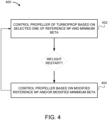
- Fig. 4 illustrates an example method 400 for operating an aircraft turboprop engine to prevent an overspeed event during an inflight restart.
- the propeller of the turboprop engine is controlled based on a selected one of a reference NP and a minimum ⁇ .
- the propeller is controlled during the inflight restart in accordance with a modified reference NP and/or a modified minimum ⁇ to maintain an actual ⁇ above the aerodynamic disking angle during the inflight restart.
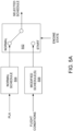
- modified schedule includes embodiments where the reference NP and/or minimum ⁇ is modified by providing a separate and dedicated modified schedule, as well as embodiments where the reference NP and/or minimum ⁇ is modified through the application of a gain or a bias to normal schedule values. In both cases, the result is that the actual propeller blade angle is maintained above the aerodynamic disking angle during the inflight restart.
- a switch 502 is used to select either a normal schedule 504 or a modified schedule 506 based on the engine state, which is either a normal state or a start state.
- the modified schedule may be selected among a plurality of modified schedules based on flight conditions.
- an inflight restart is detected using a combination of engine state and flight conditions. For example, if the engine state is an engine start and the altitude and/or aircraft speed is greater than a threshold, then an inflight restart is detected and the selected schedule corresponds to a modified schedule.
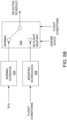
- the switch 502 is designed to make the distinction between the in-flight restart and the normal operation. In an alternative implementation illustrated in Fig.
- the distinction is not made via a switch but is instead applied more generally to the selection of a most suitable schedule given the PLA, the flight conditions, and the engine state, whereby at least one of the schedules is the modified schedule having the reference NP and/or minimum ⁇ values that will maintain the actual propeller blade angle above the aerodynamic disking angle during the inflight restart.
- detecting the inflight restart may comprise determining that the aircraft is operating within a given range of aircraft speeds and/or that SHP ⁇ 0.
- the method 400 may be implemented in the control system 210 with one or more computing device 600, an example of which is illustrated in Fig. 6 .
- the control system 210 may include more computing devices 600 operable to exchange data.
- the computing devices 600 may be the same or different types of devices.
- the control system 210 can be implemented as part of a full-authority digital engine controls (FADEC) or other similar device, including electronic engine control (EEC), engine control unit (ECU), electronic propeller control, propeller control unit, and the like. Other embodiments may also apply.
- FADEC full-authority digital engine controls
- EEC electronic engine control
- ECU engine control unit
- propeller control propeller control unit
- Other embodiments may also apply.
- the computing device 600 comprises a processing unit 602 and a memory 604 which has stored therein computer-executable instructions 606.
- the processing unit 602 may comprise any suitable devices configured to implement the method 400 such that instructions 606, when executed by the computing device 600 or other programmable apparatus, may cause the functions/acts/steps performed as part of the method 400 as described herein to be executed.
- the processing unit 602 may comprise, for example, any type of general-purpose microprocessor or microcontroller, a digital signal processing (DSP) processor, a central processing unit (CPU), an integrated circuit, a field programmable gate array (FPGA), a reconfigurable processor, other suitably programmed or programmable logic circuits, or any combination thereof.
- DSP digital signal processing
- CPU central processing unit
- FPGA field programmable gate array
- reconfigurable processor other suitably programmed or programmable logic circuits, or any combination thereof.
- the memory 604 may comprise any suitable known or other machine-readable storage medium.
- the memory 604 may comprise non-transitory computer readable storage medium, for example, but not limited to, an electronic, magnetic, optical, electromagnetic, infrared, or semiconductor system, apparatus, or device, or any suitable combination of the foregoing.
- the memory 604 may include a suitable combination of any type of computer memory that is located either internally or externally to device, for example random-access memory (RAM), read-only memory (ROM), compact disc read-only memory (CDROM), electro-optical memory, magnetooptical memory, erasable programmable read-only memory (EPROM), and electrically-erasable programmable read-only memory (EEPROM), Ferroelectric RAM (FRAM) or the like.
- Memory 604 may comprise any storage means (e.g., devices) suitable for retrievably storing machine-readable instructions 606 executable by processing unit 602.
- the methods and systems for operating an aircraft turboprop engine described herein may be implemented in a high level procedural or object oriented programming or scripting language, or a combination thereof, to communicate with or assist in the operation of a computer system, for example the computing device 600.
- the methods and systems for operating an aircraft turboprop engine may be implemented in assembly or machine language.
- the language may be a compiled or interpreted language.
- Program code for implementing the methods and systems for operating an aircraft turboprop engine may be stored on a storage media or a device, for example a ROM, a magnetic disk, an optical disc, a flash drive, or any other suitable storage media or device.
- the program code may be readable by a general or special-purpose programmable computer for configuring and operating the computer when the storage media or device is read by the computer to perform the procedures described herein.
- Embodiments of the methods and systems for operating an aircraft turboprop engine may also be considered to be implemented by way of a non-transitory computer-readable storage medium having a computer program stored thereon.
- the computer program may comprise computer-readable instructions which cause a computer, or more specifically the processing unit 602 of the computing device 600, to operate in a specific and predefined manner to perform the functions described herein, for example those described in the method 400.
- Computer-executable instructions may be in many forms, including program modules, executed by one or more computers or other devices.
- program modules include routines, programs, objects, components, data structures, etc., that perform particular tasks or implement particular abstract data types.
- functionality of the program modules may be combined or distributed as desired in various embodiments.
- the embodiments described herein are implemented by physical computer hardware, including computing devices, servers, receivers, transmitters, processors, memory, displays, and networks.
- the embodiments described herein provide useful physical machines and particularly configured computer hardware arrangements.
- the embodiments described herein are directed to electronic machines and methods implemented by electronic machines adapted for processing and transforming electromagnetic signals which represent various types of information.
- the embodiments described herein pervasively and integrally relate to machines, and their uses; and the embodiments described herein have no meaning or practical applicability outside their use with computer hardware, machines, and various hardware components. Substituting the physical hardware particularly configured to implement various acts for non-physical hardware, using mental steps for example, may substantially affect the way the embodiments work.
- connection or “coupled to” may include both direct coupling (in which two elements that are coupled to each other contact each other) and indirect coupling (in which at least one additional element is located between the two elements).
- the technical solution of embodiments may be in the form of a software product.
- the software product may be stored in a non-volatile or non-transitory storage medium, which can be a compact disk read-only memory (CD-ROM), a USB flash disk, or a removable hard disk.
- the software product includes a number of instructions that enable a computer device (personal computer, server, or network device) to execute the methods provided by the embodiments.
Landscapes
- Engineering & Computer Science (AREA)
- Chemical & Material Sciences (AREA)
- Combustion & Propulsion (AREA)
- Mechanical Engineering (AREA)
- General Engineering & Computer Science (AREA)
- Physics & Mathematics (AREA)
- Fluid Mechanics (AREA)
- Aviation & Aerospace Engineering (AREA)
- Control Of Turbines (AREA)
- Combined Controls Of Internal Combustion Engines (AREA)
Claims (8)
- Verfahren (400) zum Betreiben eines Turbopropmotors (100) für ein Flugzeug, wobei das Verfahren (400) Folgendes umfasst:Steuern (402) eines Propellers (120) des Turbopropmotors (100) auf Grundlage einem ausgewählten einen von einer Referenzpropellerdrehzahl und einem minimalen Propellerblattwinkel, während der Turbopropmotor (100) läuft;Erkennen eines Neustarts des Turbopropmotors (100) während des Flugs; und dadurch gekennzeichnet, dass es ferner Folgendes umfasst:
Steuern (404) des Propellers (120) während des Neustarts während des Flugs gemäß mindestens einem von einer modifizierten Referenzpropellerdrehzahl und einem modifizierten minimalen Propellerblattwinkel, um während des Neustarts während des Flugs einen tatsächlichen Propellerblattwinkel über einem aerodynamischen Scheibennutzungswinkel (302) aufrechtzuerhalten. - Verfahren (400) nach Anspruch 1, wobei das Erkennen des Neustarts während des Flugs Erkennen eines Motorstarts und Behandeln des Motorstarts als Neustart während des Flugs umfasst.
- Verfahren (400) nach Anspruch 1, wobei das Erkennen des Neustarts während des Flugs Folgendes umfasst:Erkennen eines Motorstarts; undals Reaktion auf das Erkennen des Motorstarts Erkennen des Neustart während des Flugs unter Verwendung von Flugbedingungen.
- Verfahren (400) nach einem der vorhergehenden Ansprüche, wobei das Erkennen des Neustarts während des Flugs Unterscheiden zwischen einem normalen Motorbetriebszustand und einem Motorzustand für den Neustart während des Flugs unter Verwendung von Flugbedingungen, eines Motorzustands und einer Schubregleranforderung umfasst.
- Verfahren (400) nach einem der Ansprüche 1 bis 3, wobei das Erkennen des Neustarts während des Flugs Erkennen eines Motorstartzustands und Erkennen, dass das Flugzeug innerhalb eines Flugzeuggeschwindigkeitsbereichs betrieben wird, umfasst.
- Verfahren (400) nach einem der vorhergehenden Ansprüche, wobei der modifizierte minimale Propellerblattwinkel einer von einem dedizierten Blattwinkelplan für Neustarts während des Flugs und dem minimalen Propellerblattwinkel mit einer angewandten Vorspannung oder einer angewandten Verstärkung ist.
- Verfahren (400) nach einem der vorhergehenden Ansprüche, wobei die modifizierte Referenzpropellerdrehzahl eines von einem dedizierten Propellerdrehzahlplan für Neustarts während des Flugs und der Referenzpropellerdrehzahl mit einer angewandten Vorspannung oder einer angewandten Verstärkung ist.
- System (200) zum Betreiben eines Turbopropmotors (100) für ein Flugzeug, wobei das System (200) Folgendes umfasst:ein Steuersystem (210), das dazu konfiguriert ist, einen Propeller (120) des Turbopropmotors (100) über einen Propelleraktor (214) zu steuern;einen Prozessor (602); undein nicht transitorisches computerlesbares Medium (604), auf dem Programmanweisungen (606) gespeichert sind, die durch den Prozessor (602) ausführbar sind, um das Verfahren (400) nach einem der vorhergehenden Ansprüche durchzuführen.
Applications Claiming Priority (1)
| Application Number | Priority Date | Filing Date | Title |
|---|---|---|---|
| US17/220,008 US11719167B2 (en) | 2021-04-01 | 2021-04-01 | Operating a turboprop engine for in-flight restart |
Publications (2)
| Publication Number | Publication Date |
|---|---|
| EP4067635A1 EP4067635A1 (de) | 2022-10-05 |
| EP4067635B1 true EP4067635B1 (de) | 2025-02-12 |
Family
ID=81326439
Family Applications (1)
| Application Number | Title | Priority Date | Filing Date |
|---|---|---|---|
| EP22166404.8A Active EP4067635B1 (de) | 2021-04-01 | 2022-04-01 | Betrieb eines turbopropmotors für einen neustart während des flugs |
Country Status (3)
| Country | Link |
|---|---|
| US (1) | US11719167B2 (de) |
| EP (1) | EP4067635B1 (de) |
| CA (1) | CA3153260A1 (de) |
Family Cites Families (12)
| Publication number | Priority date | Publication date | Assignee | Title |
|---|---|---|---|---|
| US6077040A (en) | 1998-05-01 | 2000-06-20 | United Technologies Corporation | Control system for blades for a variable pitch propeller |
| GB0816636D0 (en) * | 2008-09-12 | 2008-10-22 | Rolls Royce Plc | Controlling rotor overspeed |
| US10094293B2 (en) | 2014-08-22 | 2018-10-09 | Pratt & Whitney Canada Corp. | In flight restart system and method for free turbine engine |
| US10040565B2 (en) | 2015-09-22 | 2018-08-07 | Honeywell International Inc. | Single lever turboprop control systems and methods utilizing torque-based and power based scheduling |
| EP3369660B1 (de) * | 2017-03-02 | 2019-12-18 | Ge Avio S.r.l. | System und verfahren zum testen der steuerlogik für den propeller eines gasturbinentriebwerks |
| EP3434584B1 (de) * | 2017-07-28 | 2021-06-02 | Ge Avio S.r.l. | System und verfahren zur bestimmung der minimalen steigung und des minimalen gasgeneratorruhezustands |
| US10823113B2 (en) * | 2017-08-21 | 2020-11-03 | Pratt & Whitney Canada Corp. | Method and system for limiting power of an engine |
| EP3543112B1 (de) * | 2018-03-23 | 2020-10-21 | Ge Avio S.r.l. | System und verfahren zur kombinierten propellerdrehzahl- und propellerneigungswinkelregelung für ein turbopropellertriebwerk |
| EP3543504B1 (de) | 2018-03-23 | 2022-10-19 | Ge Avio S.r.l. | Regelungssystem und -verfahren für die begrenzung von überschwingern der propellerdrehzahl in einem turbopropellermotor |
| US11286865B2 (en) * | 2018-09-14 | 2022-03-29 | Rolls-Royce North American Technologies Inc. | Gas turbine engine with variable pitch fan and variable pitch compressor geometry |
| EP3670333B1 (de) | 2018-12-18 | 2025-11-26 | Hamilton Sundstrand Corporation | Steuerung von propellerblattwinkel mit geschlossenem regelkreis durch elektromagnetische modulation |
| IT201900010929A1 (it) | 2019-07-04 | 2021-01-04 | Ge Avio Srl | Gruppo elica ed unita' di controllo di passo |
-
2021
- 2021-04-01 US US17/220,008 patent/US11719167B2/en active Active
-
2022
- 2022-03-23 CA CA3153260A patent/CA3153260A1/en active Pending
- 2022-04-01 EP EP22166404.8A patent/EP4067635B1/de active Active
Also Published As
| Publication number | Publication date |
|---|---|
| US11719167B2 (en) | 2023-08-08 |
| CA3153260A1 (en) | 2022-10-01 |
| US20220316407A1 (en) | 2022-10-06 |
| EP4067635A1 (de) | 2022-10-05 |
Similar Documents
| Publication | Publication Date | Title |
|---|---|---|
| US11299286B2 (en) | System and method for operating a multi-engine aircraft | |
| US11414175B2 (en) | Method and system for operating an aircraft powerplant | |
| US11408357B2 (en) | Engine and propeller control system | |
| EP3447269B1 (de) | Verfahren und system zur begrenzung der leistung einer gasturbine | |
| EP3712074B1 (de) | Verfahren und system zum einstellen der leistung eines flugzeugmotors | |
| US11313286B2 (en) | Integrated propeller and engine controller | |
| US20200232395A1 (en) | Method and system for operating a gas turbine engine coupled to an aircraft propeller | |
| CN111924127B (zh) | 检测飞行器中的无命令或不可控高推力事件的系统和方法 | |
| US20190078517A1 (en) | Method and system for directing fuel flow to an engine | |
| US11852083B2 (en) | Engine and propeller control system | |
| CA3002287A1 (en) | Detection of uncommanded and uncontrollable high thrust events | |
| EP3705398B1 (de) | Verfahren und system zum betrieb eines triebwerks in einem mehrmotorigen flugzeug | |
| EP3670876B1 (de) | System und verfahren zum betreiben eines mit einem flugzeugpropeller gekoppelten gasturbinenmotors | |
| EP3656661B1 (de) | Integrierte propeller- und motorsteuerung | |
| EP4067635B1 (de) | Betrieb eines turbopropmotors für einen neustart während des flugs | |
| US12435674B2 (en) | System and method for operating a turboprop engine | |
| EP3741665B1 (de) | Verfahren und system zum betrieb einer flugzeugtriebwerksanlage |
Legal Events
| Date | Code | Title | Description |
|---|---|---|---|
| PUAI | Public reference made under article 153(3) epc to a published international application that has entered the european phase |
Free format text: ORIGINAL CODE: 0009012 |
|
| STAA | Information on the status of an ep patent application or granted ep patent |
Free format text: STATUS: THE APPLICATION HAS BEEN PUBLISHED |
|
| AK | Designated contracting states |
Kind code of ref document: A1 Designated state(s): AL AT BE BG CH CY CZ DE DK EE ES FI FR GB GR HR HU IE IS IT LI LT LU LV MC MK MT NL NO PL PT RO RS SE SI SK SM TR |
|
| STAA | Information on the status of an ep patent application or granted ep patent |
Free format text: STATUS: REQUEST FOR EXAMINATION WAS MADE |
|
| 17P | Request for examination filed |
Effective date: 20230405 |
|
| RBV | Designated contracting states (corrected) |
Designated state(s): AL AT BE BG CH CY CZ DE DK EE ES FI FR GB GR HR HU IE IS IT LI LT LU LV MC MK MT NL NO PL PT RO RS SE SI SK SM TR |
|
| RIC1 | Information provided on ipc code assigned before grant |
Ipc: F02C 9/28 20060101ALI20240704BHEP Ipc: F02C 9/00 20060101ALI20240704BHEP Ipc: F02C 7/26 20060101AFI20240704BHEP |
|
| GRAP | Despatch of communication of intention to grant a patent |
Free format text: ORIGINAL CODE: EPIDOSNIGR1 |
|
| STAA | Information on the status of an ep patent application or granted ep patent |
Free format text: STATUS: GRANT OF PATENT IS INTENDED |
|
| INTG | Intention to grant announced |
Effective date: 20240829 |
|
| GRAS | Grant fee paid |
Free format text: ORIGINAL CODE: EPIDOSNIGR3 |
|
| GRAA | (expected) grant |
Free format text: ORIGINAL CODE: 0009210 |
|
| STAA | Information on the status of an ep patent application or granted ep patent |
Free format text: STATUS: THE PATENT HAS BEEN GRANTED |
|
| AK | Designated contracting states |
Kind code of ref document: B1 Designated state(s): AL AT BE BG CH CY CZ DE DK EE ES FI FR GB GR HR HU IE IS IT LI LT LU LV MC MK MT NL NO PL PT RO RS SE SI SK SM TR |
|
| REG | Reference to a national code |
Ref country code: GB Ref legal event code: FG4D |
|
| REG | Reference to a national code |
Ref country code: CH Ref legal event code: EP |
|
| REG | Reference to a national code |
Ref country code: DE Ref legal event code: R096 Ref document number: 602022010356 Country of ref document: DE |
|
| REG | Reference to a national code |
Ref country code: IE Ref legal event code: FG4D |
|
| REG | Reference to a national code |
Ref country code: NL Ref legal event code: MP Effective date: 20250212 |
|
| PG25 | Lapsed in a contracting state [announced via postgrant information from national office to epo] |
Ref country code: RS Free format text: LAPSE BECAUSE OF FAILURE TO SUBMIT A TRANSLATION OF THE DESCRIPTION OR TO PAY THE FEE WITHIN THE PRESCRIBED TIME-LIMIT Effective date: 20250512 |
|
| PG25 | Lapsed in a contracting state [announced via postgrant information from national office to epo] |
Ref country code: FI Free format text: LAPSE BECAUSE OF FAILURE TO SUBMIT A TRANSLATION OF THE DESCRIPTION OR TO PAY THE FEE WITHIN THE PRESCRIBED TIME-LIMIT Effective date: 20250212 |
|
| PG25 | Lapsed in a contracting state [announced via postgrant information from national office to epo] |
Ref country code: PL Free format text: LAPSE BECAUSE OF FAILURE TO SUBMIT A TRANSLATION OF THE DESCRIPTION OR TO PAY THE FEE WITHIN THE PRESCRIBED TIME-LIMIT Effective date: 20250212 |
|
| PGFP | Annual fee paid to national office [announced via postgrant information from national office to epo] |
Ref country code: DE Payment date: 20250319 Year of fee payment: 4 |
|
| PG25 | Lapsed in a contracting state [announced via postgrant information from national office to epo] |
Ref country code: ES Free format text: LAPSE BECAUSE OF FAILURE TO SUBMIT A TRANSLATION OF THE DESCRIPTION OR TO PAY THE FEE WITHIN THE PRESCRIBED TIME-LIMIT Effective date: 20250212 |
|
| REG | Reference to a national code |
Ref country code: LT Ref legal event code: MG9D |
|
| PG25 | Lapsed in a contracting state [announced via postgrant information from national office to epo] |
Ref country code: IS Free format text: LAPSE BECAUSE OF FAILURE TO SUBMIT A TRANSLATION OF THE DESCRIPTION OR TO PAY THE FEE WITHIN THE PRESCRIBED TIME-LIMIT Effective date: 20250612 Ref country code: NO Free format text: LAPSE BECAUSE OF FAILURE TO SUBMIT A TRANSLATION OF THE DESCRIPTION OR TO PAY THE FEE WITHIN THE PRESCRIBED TIME-LIMIT Effective date: 20250512 |
|
| PG25 | Lapsed in a contracting state [announced via postgrant information from national office to epo] |
Ref country code: NL Free format text: LAPSE BECAUSE OF FAILURE TO SUBMIT A TRANSLATION OF THE DESCRIPTION OR TO PAY THE FEE WITHIN THE PRESCRIBED TIME-LIMIT Effective date: 20250212 |
|
| PG25 | Lapsed in a contracting state [announced via postgrant information from national office to epo] |
Ref country code: HR Free format text: LAPSE BECAUSE OF FAILURE TO SUBMIT A TRANSLATION OF THE DESCRIPTION OR TO PAY THE FEE WITHIN THE PRESCRIBED TIME-LIMIT Effective date: 20250212 |
|
| PG25 | Lapsed in a contracting state [announced via postgrant information from national office to epo] |
Ref country code: PT Free format text: LAPSE BECAUSE OF FAILURE TO SUBMIT A TRANSLATION OF THE DESCRIPTION OR TO PAY THE FEE WITHIN THE PRESCRIBED TIME-LIMIT Effective date: 20250612 Ref country code: LV Free format text: LAPSE BECAUSE OF FAILURE TO SUBMIT A TRANSLATION OF THE DESCRIPTION OR TO PAY THE FEE WITHIN THE PRESCRIBED TIME-LIMIT Effective date: 20250212 |
|
| PG25 | Lapsed in a contracting state [announced via postgrant information from national office to epo] |
Ref country code: GR Free format text: LAPSE BECAUSE OF FAILURE TO SUBMIT A TRANSLATION OF THE DESCRIPTION OR TO PAY THE FEE WITHIN THE PRESCRIBED TIME-LIMIT Effective date: 20250513 Ref country code: BG Free format text: LAPSE BECAUSE OF FAILURE TO SUBMIT A TRANSLATION OF THE DESCRIPTION OR TO PAY THE FEE WITHIN THE PRESCRIBED TIME-LIMIT Effective date: 20250212 |
|
| REG | Reference to a national code |
Ref country code: AT Ref legal event code: MK05 Ref document number: 1766230 Country of ref document: AT Kind code of ref document: T Effective date: 20250212 |
|
| PG25 | Lapsed in a contracting state [announced via postgrant information from national office to epo] |
Ref country code: SE Free format text: LAPSE BECAUSE OF FAILURE TO SUBMIT A TRANSLATION OF THE DESCRIPTION OR TO PAY THE FEE WITHIN THE PRESCRIBED TIME-LIMIT Effective date: 20250212 |
|
| PG25 | Lapsed in a contracting state [announced via postgrant information from national office to epo] |
Ref country code: SM Free format text: LAPSE BECAUSE OF FAILURE TO SUBMIT A TRANSLATION OF THE DESCRIPTION OR TO PAY THE FEE WITHIN THE PRESCRIBED TIME-LIMIT Effective date: 20250212 |
|
| PG25 | Lapsed in a contracting state [announced via postgrant information from national office to epo] |
Ref country code: DK Free format text: LAPSE BECAUSE OF FAILURE TO SUBMIT A TRANSLATION OF THE DESCRIPTION OR TO PAY THE FEE WITHIN THE PRESCRIBED TIME-LIMIT Effective date: 20250212 |
|
| PG25 | Lapsed in a contracting state [announced via postgrant information from national office to epo] |
Ref country code: IT Free format text: LAPSE BECAUSE OF FAILURE TO SUBMIT A TRANSLATION OF THE DESCRIPTION OR TO PAY THE FEE WITHIN THE PRESCRIBED TIME-LIMIT Effective date: 20250212 |
|
| PG25 | Lapsed in a contracting state [announced via postgrant information from national office to epo] |
Ref country code: AT Free format text: LAPSE BECAUSE OF FAILURE TO SUBMIT A TRANSLATION OF THE DESCRIPTION OR TO PAY THE FEE WITHIN THE PRESCRIBED TIME-LIMIT Effective date: 20250212 |
|
| PG25 | Lapsed in a contracting state [announced via postgrant information from national office to epo] |
Ref country code: CZ Free format text: LAPSE BECAUSE OF FAILURE TO SUBMIT A TRANSLATION OF THE DESCRIPTION OR TO PAY THE FEE WITHIN THE PRESCRIBED TIME-LIMIT Effective date: 20250212 Ref country code: EE Free format text: LAPSE BECAUSE OF FAILURE TO SUBMIT A TRANSLATION OF THE DESCRIPTION OR TO PAY THE FEE WITHIN THE PRESCRIBED TIME-LIMIT Effective date: 20250212 |
|
| PG25 | Lapsed in a contracting state [announced via postgrant information from national office to epo] |
Ref country code: RO Free format text: LAPSE BECAUSE OF FAILURE TO SUBMIT A TRANSLATION OF THE DESCRIPTION OR TO PAY THE FEE WITHIN THE PRESCRIBED TIME-LIMIT Effective date: 20250212 |
|
| PG25 | Lapsed in a contracting state [announced via postgrant information from national office to epo] |
Ref country code: SK Free format text: LAPSE BECAUSE OF FAILURE TO SUBMIT A TRANSLATION OF THE DESCRIPTION OR TO PAY THE FEE WITHIN THE PRESCRIBED TIME-LIMIT Effective date: 20250212 |
|
| REG | Reference to a national code |
Ref country code: DE Ref legal event code: R097 Ref document number: 602022010356 Country of ref document: DE |
|
| REG | Reference to a national code |
Ref country code: CH Ref legal event code: H13 Free format text: ST27 STATUS EVENT CODE: U-0-0-H10-H13 (AS PROVIDED BY THE NATIONAL OFFICE) Effective date: 20251125 |
|
| PG25 | Lapsed in a contracting state [announced via postgrant information from national office to epo] |
Ref country code: LU Free format text: LAPSE BECAUSE OF NON-PAYMENT OF DUE FEES Effective date: 20250401 |
|
| PLBE | No opposition filed within time limit |
Free format text: ORIGINAL CODE: 0009261 |
|
| STAA | Information on the status of an ep patent application or granted ep patent |
Free format text: STATUS: NO OPPOSITION FILED WITHIN TIME LIMIT |
|
| PG25 | Lapsed in a contracting state [announced via postgrant information from national office to epo] |
Ref country code: MC Free format text: LAPSE BECAUSE OF FAILURE TO SUBMIT A TRANSLATION OF THE DESCRIPTION OR TO PAY THE FEE WITHIN THE PRESCRIBED TIME-LIMIT Effective date: 20250212 |
|
| REG | Reference to a national code |
Ref country code: BE Ref legal event code: MM Effective date: 20250430 |
|
| PG25 | Lapsed in a contracting state [announced via postgrant information from national office to epo] |
Ref country code: BE Free format text: LAPSE BECAUSE OF NON-PAYMENT OF DUE FEES Effective date: 20250430 |
|
| PG25 | Lapsed in a contracting state [announced via postgrant information from national office to epo] |
Ref country code: CH Free format text: LAPSE BECAUSE OF NON-PAYMENT OF DUE FEES Effective date: 20250430 |
|
| 26N | No opposition filed |
Effective date: 20251113 |
|
| PGFP | Annual fee paid to national office [announced via postgrant information from national office to epo] |
Ref country code: GB Payment date: 20260319 Year of fee payment: 5 |
|
| PG25 | Lapsed in a contracting state [announced via postgrant information from national office to epo] |
Ref country code: IE Free format text: LAPSE BECAUSE OF NON-PAYMENT OF DUE FEES Effective date: 20250401 |
|
| PGFP | Annual fee paid to national office [announced via postgrant information from national office to epo] |
Ref country code: FR Payment date: 20260320 Year of fee payment: 5 |