EP4067687A1 - Bremsenverschleissstiftarchitektur - Google Patents
Bremsenverschleissstiftarchitektur Download PDFInfo
- Publication number
- EP4067687A1 EP4067687A1 EP21166381.0A EP21166381A EP4067687A1 EP 4067687 A1 EP4067687 A1 EP 4067687A1 EP 21166381 A EP21166381 A EP 21166381A EP 4067687 A1 EP4067687 A1 EP 4067687A1
- Authority
- EP
- European Patent Office
- Prior art keywords
- pin
- architecture
- brake
- wear
- sensor
- Prior art date
- Legal status (The legal status is an assumption and is not a legal conclusion. Google has not performed a legal analysis and makes no representation as to the accuracy of the status listed.)
- Granted
Links
Images

Classifications
-
- F—MECHANICAL ENGINEERING; LIGHTING; HEATING; WEAPONS; BLASTING
- F16—ENGINEERING ELEMENTS AND UNITS; GENERAL MEASURES FOR PRODUCING AND MAINTAINING EFFECTIVE FUNCTIONING OF MACHINES OR INSTALLATIONS; THERMAL INSULATION IN GENERAL
- F16D—COUPLINGS FOR TRANSMITTING ROTATION; CLUTCHES; BRAKES
- F16D66/00—Arrangements for monitoring working conditions, e.g. wear, temperature
- F16D66/02—Apparatus for indicating wear
- F16D66/021—Apparatus for indicating wear using electrical detection or indication means
- F16D66/022—Apparatus for indicating wear using electrical detection or indication means indicating that a lining is worn to minimum allowable thickness
- F16D66/025—Apparatus for indicating wear using electrical detection or indication means indicating that a lining is worn to minimum allowable thickness sensing the position of parts of the brake system other than the braking members, e.g. limit switches mounted on primary cylinders
-
- F—MECHANICAL ENGINEERING; LIGHTING; HEATING; WEAPONS; BLASTING
- F16—ENGINEERING ELEMENTS AND UNITS; GENERAL MEASURES FOR PRODUCING AND MAINTAINING EFFECTIVE FUNCTIONING OF MACHINES OR INSTALLATIONS; THERMAL INSULATION IN GENERAL
- F16D—COUPLINGS FOR TRANSMITTING ROTATION; CLUTCHES; BRAKES
- F16D66/00—Arrangements for monitoring working conditions, e.g. wear, temperature
- F16D66/02—Apparatus for indicating wear
- F16D66/021—Apparatus for indicating wear using electrical detection or indication means
- F16D66/026—Apparatus for indicating wear using electrical detection or indication means indicating different degrees of lining wear
- F16D66/027—Sensors therefor
-
- B—PERFORMING OPERATIONS; TRANSPORTING
- B60—VEHICLES IN GENERAL
- B60T—VEHICLE BRAKE CONTROL SYSTEMS OR PARTS THEREOF; BRAKE CONTROL SYSTEMS OR PARTS THEREOF, IN GENERAL; ARRANGEMENT OF BRAKING ELEMENTS ON VEHICLES IN GENERAL; PORTABLE DEVICES FOR PREVENTING UNWANTED MOVEMENT OF VEHICLES; VEHICLE MODIFICATIONS TO FACILITATE COOLING OF BRAKES
- B60T17/00—Component parts, details, or accessories of power brake systems not covered by groups B60T8/00, B60T13/00 or B60T15/00, or presenting other characteristic features
- B60T17/18—Safety devices; Monitoring
- B60T17/22—Devices for monitoring or checking brake systems; Signal devices
-
- B—PERFORMING OPERATIONS; TRANSPORTING
- B64—AIRCRAFT; AVIATION; COSMONAUTICS
- B64C—AEROPLANES; HELICOPTERS
- B64C25/00—Alighting gear
- B64C25/32—Alighting gear characterised by elements which contact the ground or similar surface
- B64C25/34—Alighting gear characterised by elements which contact the ground or similar surface wheeled type, e.g. multi-wheeled bogies
-
- B—PERFORMING OPERATIONS; TRANSPORTING
- B64—AIRCRAFT; AVIATION; COSMONAUTICS
- B64C—AEROPLANES; HELICOPTERS
- B64C25/00—Alighting gear
- B64C25/32—Alighting gear characterised by elements which contact the ground or similar surface
- B64C25/42—Arrangement or adaptation of brakes
- B64C25/44—Actuating mechanisms
-
- F—MECHANICAL ENGINEERING; LIGHTING; HEATING; WEAPONS; BLASTING
- F16—ENGINEERING ELEMENTS AND UNITS; GENERAL MEASURES FOR PRODUCING AND MAINTAINING EFFECTIVE FUNCTIONING OF MACHINES OR INSTALLATIONS; THERMAL INSULATION IN GENERAL
- F16D—COUPLINGS FOR TRANSMITTING ROTATION; CLUTCHES; BRAKES
- F16D55/00—Brakes with substantially-radial braking surfaces pressed together in axial direction, e.g. disc brakes
- F16D55/24—Brakes with substantially-radial braking surfaces pressed together in axial direction, e.g. disc brakes with a plurality of axially-movable discs, lamellae, or pads, pressed from one side towards an axially-located member
- F16D55/26—Brakes with substantially-radial braking surfaces pressed together in axial direction, e.g. disc brakes with a plurality of axially-movable discs, lamellae, or pads, pressed from one side towards an axially-located member without self-tightening action
- F16D55/36—Brakes with a plurality of rotating discs all lying side by side
-
- F—MECHANICAL ENGINEERING; LIGHTING; HEATING; WEAPONS; BLASTING
- F16—ENGINEERING ELEMENTS AND UNITS; GENERAL MEASURES FOR PRODUCING AND MAINTAINING EFFECTIVE FUNCTIONING OF MACHINES OR INSTALLATIONS; THERMAL INSULATION IN GENERAL
- F16D—COUPLINGS FOR TRANSMITTING ROTATION; CLUTCHES; BRAKES
- F16D66/00—Arrangements for monitoring working conditions, e.g. wear, temperature
- F16D66/02—Apparatus for indicating wear
-
- F—MECHANICAL ENGINEERING; LIGHTING; HEATING; WEAPONS; BLASTING
- F16—ENGINEERING ELEMENTS AND UNITS; GENERAL MEASURES FOR PRODUCING AND MAINTAINING EFFECTIVE FUNCTIONING OF MACHINES OR INSTALLATIONS; THERMAL INSULATION IN GENERAL
- F16D—COUPLINGS FOR TRANSMITTING ROTATION; CLUTCHES; BRAKES
- F16D66/00—Arrangements for monitoring working conditions, e.g. wear, temperature
- F16D66/02—Apparatus for indicating wear
- F16D66/021—Apparatus for indicating wear using electrical detection or indication means
- F16D66/028—Apparatus for indicating wear using electrical detection or indication means with non-electrical sensors or signal transmission, e.g. magnetic, optical
-
- F—MECHANICAL ENGINEERING; LIGHTING; HEATING; WEAPONS; BLASTING
- F16—ENGINEERING ELEMENTS AND UNITS; GENERAL MEASURES FOR PRODUCING AND MAINTAINING EFFECTIVE FUNCTIONING OF MACHINES OR INSTALLATIONS; THERMAL INSULATION IN GENERAL
- F16D—COUPLINGS FOR TRANSMITTING ROTATION; CLUTCHES; BRAKES
- F16D55/00—Brakes with substantially-radial braking surfaces pressed together in axial direction, e.g. disc brakes
- F16D2055/0004—Parts or details of disc brakes
- F16D2055/0058—Fully lined, i.e. braking surface extending over the entire disc circumference
-
- F—MECHANICAL ENGINEERING; LIGHTING; HEATING; WEAPONS; BLASTING
- F16—ENGINEERING ELEMENTS AND UNITS; GENERAL MEASURES FOR PRODUCING AND MAINTAINING EFFECTIVE FUNCTIONING OF MACHINES OR INSTALLATIONS; THERMAL INSULATION IN GENERAL
- F16D—COUPLINGS FOR TRANSMITTING ROTATION; CLUTCHES; BRAKES
- F16D66/00—Arrangements for monitoring working conditions, e.g. wear, temperature
- F16D2066/001—Temperature
-
- F—MECHANICAL ENGINEERING; LIGHTING; HEATING; WEAPONS; BLASTING
- F16—ENGINEERING ELEMENTS AND UNITS; GENERAL MEASURES FOR PRODUCING AND MAINTAINING EFFECTIVE FUNCTIONING OF MACHINES OR INSTALLATIONS; THERMAL INSULATION IN GENERAL
- F16D—COUPLINGS FOR TRANSMITTING ROTATION; CLUTCHES; BRAKES
- F16D66/00—Arrangements for monitoring working conditions, e.g. wear, temperature
- F16D2066/003—Position, angle or speed
-
- F—MECHANICAL ENGINEERING; LIGHTING; HEATING; WEAPONS; BLASTING
- F16—ENGINEERING ELEMENTS AND UNITS; GENERAL MEASURES FOR PRODUCING AND MAINTAINING EFFECTIVE FUNCTIONING OF MACHINES OR INSTALLATIONS; THERMAL INSULATION IN GENERAL
- F16D—COUPLINGS FOR TRANSMITTING ROTATION; CLUTCHES; BRAKES
- F16D66/00—Arrangements for monitoring working conditions, e.g. wear, temperature
- F16D2066/006—Arrangements for monitoring working conditions, e.g. wear, temperature without direct measurement of the quantity monitored, e.g. wear or temperature calculated form force and duration of braking
Definitions
- the present disclosure concerns an architecture to enable electronic monitoring of a brake such as, but not exclusively, an aircraft brake.
- Vehicle brakes comprise a brake disk or plate, or, more often, a stack of brake disks that is actuated to slow down the vehicle.
- stators and rotors stationary and rotary parts of the brake plate or stack
- the pressure exercised determines the presence of a friction between the disks, which provides braking action and allows the wheel to stop rotating. It is safety critical that brakes remain functional and reliable. Over their lifetime, brake discs will suffer wear (in the form of eroded material from either the stators or rotors) due to the frictional engagement of the brake disks during braking actions. The final effect translates into a thinning process of the brake plate or stack.
- brake disks have been made of robust metals such as steel to be able to withstand these conditions. More recently, brake disks made of carbon-carbon composites have become popular, as such materials are not only extremely durable and highly temperature resistance, but they are also lightweight compared to steel. This weight reduction is particularly advantageous in aircraft where weight should be minimised.
- the brakes wear is monitored through the use of a wear pin.
- This is a small pin attached to and extending from the brake disks used to provide a visual indication of the amount of wear of the disk.
- the wear pin extends a given distance from the brake housing, and it is generally firmly connected to the pressure plate of the brake stack, and is perpendicular to the plate.
- the overall thickness of the brake stack reduces.
- the pressure plate gets pushed towards the stack of rotors and stators to keep the overall assembly compact, and the wear pin moves solidly in the same direction. Due to this phenomenon, over time, the portion of wear pin that extends from the brake housing will be smaller and smaller. An engineer performing aircraft maintenance will measure the exposed length of the pin e.g.
- Braking of vehicles also generates heat due to the frictional engagement between the stators and rotors of the brake's stack. It is also important to monitor the brake temperature especially in applications where high temperatures can cause safety issues e.g. in aircraft.
- temperature is measured by means of a thermocouple that is generally installed in a rib of the torque plate.
- the temperature sensor is used to warn the pilot, in the cockpit, of a so-called 'hot brakes' condition. In the event of such a condition being indicated, the pilot is required to delay take-off until the warning disappears.
- Such temperature sensors are, however, not particularly accurate since the location of the sensor is not ideal with respect to the heat sink that records the temperature and significant lags and offsets can arise in the sensor readings.
- the 'hot brake' condition warning is set using very conservative thresholds. This can lead to take-off delays that are not actually necessary.
- more accurate indications of the brakes temperature can help in the development of more sophisticated controls and health-monitoring algorithms that can help in improving the operational efficiency of brakes, while enforcing health-related constraints.
- the present disclosure provides an architecture that provides automatic monitoring of brake conditions making use of a wear pin on a brake.
- the disclosure can therefore make use of the fact that, for example, a wear pin is required to be provided on an aircraft brake, by integrating monitoring functions into the pin. This means that the automatic monitoring components are not taking up more space on the brake than is already taken up by the compulsory wear pin.
- an architecture for monitoring a brake assembly comprising a wear pin configured to be mounted to a pressure plate of the brake assembly to provide a visual indication of brake displacement during braking, characterised in that the wear pin is a hollow cylindrical pin and wherein one or more sensors is mounted inside the hollow pin to provide an indication of displacement and/or temperature.
- the sensors may comprise a displacement sensor to provide an indication of wear of the brake assembly based on an exposure length of the wear pin and/or a temperature sensor to provide an indication of the temperature of the brake assembly.
- the displacement sensor may be provided at one end of the pin and the temperature sensor at the other end of the pin.
- the architecture may further comprise power, transmission and/or control electronics mounted inside the wear pin.
- a brake assembly comprising a pressure plate arranged to engage a rotating part to be braked, on actuation of the brake assembly, and an architecture as described above attached to and extending from the pressure plate.
- a landing gear of an aircraft comprising a landing gear arm, an axle extending essentially transverse to the landing gear arm and a wheel at each end of the axle, and further comprising a brake assembly for braking each wheel, the brake assembly comprising a pressure plate arranged to engage a rotating part of the wheel to cause braking of the wheel, and an architecture as described above, and further comprising a target arranged on the landing gear arm to receive signals from the one or more sensors.
- Figure 1 shows an aircraft landing gear as one environment in which the wear pin of the disclosure can be utilised.
- Fig. 1 shows, by way of example only, a landing gear arm 10 from which extends an axle 20.
- a wheel 30, 40 is provided at each end of the axle.
- the wear pin 1 is shown in Fig. 1 protruding from the wheel 40. The more the brake disk is worn, the greater its displacement to engage with the inner rotating wheel assembly (not shown) when braking.
- the wear pin 1 is attached to the brake disk and so the greater the brake disk displacement, the smaller the exposed length L of the pin 1 from the wheel 40. Measurement of the exposed length L allows a manual determination of the degree of wear of the brake disk.
- the present disclosure provides an architecture that enables automated monitoring of brake wear and/or brake temperature by forming the wear pin 1 as a hollow pin and mounting monitoring components inside the hollow interior of the pin 1.
- Fig 2A shows the pin 1 having a first end 11 arranged to be attached to the pressure plate or brake disk (not shown), and a second, opposite end 12 arranged to extend from the wheel to, in this case, protrude towards the landing gear.
- the pin is hollow and monitoring components are mounted in the hollow interior 13. Whilst different monitoring components may be provided in the pin, as will be described further below, in the example shown in Fig. 2B , a temperature sensor and a displacement sensor are provided (here, the temperature sensor 14 is provided at the first end 11 and the displacement sensor 15 at the second end 12. Other components or circuitry 16 for e.g. power supply, conditioning, data transmission etc. may also be mounted inside the pin 1.
- the displacement sensor 15 is preferably located at an end e.g. the second end of the pin, but the displacement sensor could be mounted at any position inside the pin so long as that position is known and calibrated with respect to the target.
- the target 17 may be e.g. a metal plate or coating at the target site.
- the type of target will depend on the type of displacement sensor. Many different types of sensor can be used e.g. an infrared sensor or an ultrasonic sensor or an eddy current sensor. Those skilled in the art will be aware of different sensors that can be used to determine distance between the sensor and a target and the disclosure is not limited to any one type of sensor.
- a temperature sensor 14 may be provided in the pin to monitor the brake temperature in a reliable manner to provide a more accurate and faster temperature reading.
- Location of the temperature sensor 14 in the wear pin 1 means that the temperature sensor can be accurately positioned close to where the temperature increase is most likely to occur.
- the temperature sensor 14 is located in the pin at the end attached to the brake disk/pressure plate.
- a small hole could, for example, be provided in the first end of the pin 1 so that the temperature sensor has direct or almost direct contact with the brake disk whose temperature is being monitored. This may, however, not be necessary, and a temperature sensor mounted inside the pin without any modification to the pin or the pressure plate will also be useful in collecting thermal information about the brake.
- the other possible electronics 17 may be to e.g. provide power to the sensors (if required), to provide signal conditioning (if required) and to support date transmission if required.
- Power may be provided through wires into the pin or wirelessly.
- local power may be used e.g. with local power storage.
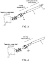
- FIG. 3 shows a more detailed example of a wear pin 1 according to the disclosure.
- Fig. 3 shows the wear pin 1 as shown in Figs 1 to 3 .
- a displacement sensor 15' here an eddy current sensor, is inserted into the end of the pin 1 that will protrude from the brake.
- a temperature sensor, here thermocouple 14' is inserted into the pin at the other end, which will be attached to the brake.
- a target 17 is provided that will be positioned at a location opposite the displacement sensor end of the pin when the pin is in place, such that the target will detect signals coming from the sensor 15'.
- the displacement can be sensed e.g. by detecting the time it takes for emitted signals to be reflected back to the sensor by the target. Alternatively, the strength of the signals can be detected as an indication of displacement. Other ways of sensing will be apparent to those skilled in the art.
- the wear pin 1' only has a displacement sensor 15" and does not have a temperature sensor.
- embodiments can be envisaged (not shown here) that include a temperature sensor but no displacement sensor.
- the pin can even be furnished with sensors/circuitry as needed for any particular situation and then modified as required by removing/replacing components.
- the present disclosure allows accurate information to be obtained on any type of platform e.g. different types of aircraft (hydraulic, electrical, hybrid) or other platforms such as other vehicles or machines.
- the 'intelligent' wear pin of the disclosure can be part of an advanced intelligent control, maintenance. Prognostic, diagnostic system and enables brake wear and/or temperature to be accurately and automatically monitored without the need for down time and human effort.
Landscapes
- Engineering & Computer Science (AREA)
- General Engineering & Computer Science (AREA)
- Mechanical Engineering (AREA)
- Aviation & Aerospace Engineering (AREA)
- Transportation (AREA)
- Braking Arrangements (AREA)
Priority Applications (2)
| Application Number | Priority Date | Filing Date | Title |
|---|---|---|---|
| EP21166381.0A EP4067687B1 (de) | 2021-03-31 | 2021-03-31 | Bremsenverschleissstiftarchitektur |
| US17/680,420 US11965569B2 (en) | 2021-03-31 | 2022-02-25 | Brake wear pin architecture |
Applications Claiming Priority (1)
| Application Number | Priority Date | Filing Date | Title |
|---|---|---|---|
| EP21166381.0A EP4067687B1 (de) | 2021-03-31 | 2021-03-31 | Bremsenverschleissstiftarchitektur |
Publications (2)
| Publication Number | Publication Date |
|---|---|
| EP4067687A1 true EP4067687A1 (de) | 2022-10-05 |
| EP4067687B1 EP4067687B1 (de) | 2024-12-25 |
Family
ID=75339595
Family Applications (1)
| Application Number | Title | Priority Date | Filing Date |
|---|---|---|---|
| EP21166381.0A Active EP4067687B1 (de) | 2021-03-31 | 2021-03-31 | Bremsenverschleissstiftarchitektur |
Country Status (2)
| Country | Link |
|---|---|
| US (1) | US11965569B2 (de) |
| EP (1) | EP4067687B1 (de) |
Families Citing this family (1)
| Publication number | Priority date | Publication date | Assignee | Title |
|---|---|---|---|---|
| EP4382373B1 (de) * | 2022-12-05 | 2025-10-15 | Collins Aerospace Ireland, Limited | Vorrichtung zur erfassung einer flugzeugbremsanordnung |
Citations (4)
| Publication number | Priority date | Publication date | Assignee | Title |
|---|---|---|---|---|
| DE2734786A1 (de) * | 1977-08-02 | 1979-02-08 | Daimler Benz Ag | Bremsbelag-verschleissanzeigevorrichtung |
| US4658936A (en) * | 1985-07-25 | 1987-04-21 | Goodyear Aerospace Corporation | Brake temperature and wear indicator |
| US20190329755A1 (en) * | 2018-04-27 | 2019-10-31 | Honeywell International Inc. | Determining estimated remaining use of brake assembly by transceiver |
| US20200307530A1 (en) * | 2019-03-29 | 2020-10-01 | Goodrich Corporation | Retractable electronic wear pin |
Family Cites Families (13)
| Publication number | Priority date | Publication date | Assignee | Title |
|---|---|---|---|---|
| JPS59127934U (ja) | 1983-02-15 | 1984-08-28 | 松下電器産業株式会社 | 摩耗度兼温度検知装置 |
| US6450300B1 (en) * | 1998-10-21 | 2002-09-17 | Meritor Heavy Vehicle Systems, Llc | Packaging a temperature sensing brake lining wear indicator in a brake shoe assembly |
| US7766130B2 (en) * | 2004-11-19 | 2010-08-03 | Honeywell International Inc. | Wear pin assemblies for carbon-carbon composite brake systems |
| US9441692B2 (en) * | 2008-03-11 | 2016-09-13 | Honeywell International Inc. | Proximity sensor for brake wear detection |
| US9964168B1 (en) | 2016-11-09 | 2018-05-08 | GM Global Technology Operations LLC | Brake pad wear and temperature sensor |
| EP3483018B1 (de) * | 2017-11-08 | 2022-08-10 | Ratier-Figeac SAS | Bremsüberwachungssystem |
| EP3740695A4 (de) | 2018-01-16 | 2021-02-24 | SAF-Holland, Inc. | Kombinierter bremsbelagverschleisssensor und bremstemperatursensor |
| US10436271B2 (en) * | 2018-02-15 | 2019-10-08 | Bendix Spicer Foundation Brake Llc | Mechanical pad wear indicator |
| GB2571359A (en) * | 2018-02-27 | 2019-08-28 | Airbus Operations Ltd | Brake monitoring |
| US10941826B2 (en) * | 2018-09-12 | 2021-03-09 | Honeywell International Inc. | Determining estimated remaining use of brake assembly |
| US11215436B2 (en) * | 2018-11-08 | 2022-01-04 | Honeywell International Inc. | Measuring the length of a wear indicator |
| US20230211767A1 (en) * | 2022-01-06 | 2023-07-06 | Hydro-Aire Aerospace Corporation | Aircraft braking indicators |
| US11965568B2 (en) * | 2022-03-10 | 2024-04-23 | Honeywell International Inc. | Sensing and analyzing brake wear data |
-
2021
- 2021-03-31 EP EP21166381.0A patent/EP4067687B1/de active Active
-
2022
- 2022-02-25 US US17/680,420 patent/US11965569B2/en active Active
Patent Citations (4)
| Publication number | Priority date | Publication date | Assignee | Title |
|---|---|---|---|---|
| DE2734786A1 (de) * | 1977-08-02 | 1979-02-08 | Daimler Benz Ag | Bremsbelag-verschleissanzeigevorrichtung |
| US4658936A (en) * | 1985-07-25 | 1987-04-21 | Goodyear Aerospace Corporation | Brake temperature and wear indicator |
| US20190329755A1 (en) * | 2018-04-27 | 2019-10-31 | Honeywell International Inc. | Determining estimated remaining use of brake assembly by transceiver |
| US20200307530A1 (en) * | 2019-03-29 | 2020-10-01 | Goodrich Corporation | Retractable electronic wear pin |
Also Published As
| Publication number | Publication date |
|---|---|
| US20220316541A1 (en) | 2022-10-06 |
| EP4067687B1 (de) | 2024-12-25 |
| US11965569B2 (en) | 2024-04-23 |
Similar Documents
| Publication | Publication Date | Title |
|---|---|---|
| US5939978A (en) | Temperature sensing brake lining wear indicator | |
| US8437934B2 (en) | Temperature and wear and tear sensor for brake or clutch devices | |
| US8717159B2 (en) | Vehicle brake monitoring system and method | |
| US6581728B2 (en) | Brake shoe proximity sensor | |
| US7673721B2 (en) | Electrically actuated aircraft brakes | |
| US8026802B2 (en) | Vehicle abnormality detection method and device thereof and sensor unit thereof | |
| US5909171A (en) | Temperature sensing brake lining wear indicator | |
| CN102777520B (zh) | 用于监控行车制动器的空隙和制动衬片磨损的方法和装置 | |
| GB2558769B (en) | Controller for a braking system of a vehicle | |
| US20050212357A1 (en) | Brake monitoring and sensor system for sensing temperature and wear | |
| US6250430B1 (en) | System and method for determining brake lining wear using a temperature detector and a brake actuation system | |
| US11965569B2 (en) | Brake wear pin architecture | |
| KR20180034533A (ko) | 브레이크 라이닝의 마모 거동을 분석하기 위한 방법 및 시스템 | |
| US6260665B1 (en) | System and method for determining brake lining wear based on cooling wave propagation time | |
| CN110537034B (zh) | 组合式地检测特别是机动车的制动设备的部件的磨损 | |
| EP0999377B1 (de) | Bremsschuh mit Belagverschleiss- und Temperatursensor | |
| CN118025111A (zh) | 用于监控车辆的车轮制动器的系统以及具有该系统的车辆 | |
| WO2025073973A1 (en) | Vehicle monitoring system and method | |
| EP4382373B1 (de) | Vorrichtung zur erfassung einer flugzeugbremsanordnung | |
| EP4336063A1 (de) | Elektrisch betriebene bremsanordnung, computerimplementiertes verfahren zur steuerung einer elektrisch betriebenen bremsanordnung, computerprogramm und nichtflüchtiger datenträger | |
| EP4477486A1 (de) | Bremssystem und -verfahren für schwerlastfahrzeuge | |
| Lee et al. | Brake Pad Wear Monitor using MOC (Motor on Caliper) EPB ECU | |
| US20070023236A1 (en) | Wear-protected system for monitoring vehicle brakeshoe wear |
Legal Events
| Date | Code | Title | Description |
|---|---|---|---|
| PUAI | Public reference made under article 153(3) epc to a published international application that has entered the european phase |
Free format text: ORIGINAL CODE: 0009012 |
|
| STAA | Information on the status of an ep patent application or granted ep patent |
Free format text: STATUS: THE APPLICATION HAS BEEN PUBLISHED |
|
| AK | Designated contracting states |
Kind code of ref document: A1 Designated state(s): AL AT BE BG CH CY CZ DE DK EE ES FI FR GB GR HR HU IE IS IT LI LT LU LV MC MK MT NL NO PL PT RO RS SE SI SK SM TR |
|
| STAA | Information on the status of an ep patent application or granted ep patent |
Free format text: STATUS: REQUEST FOR EXAMINATION WAS MADE |
|
| 17P | Request for examination filed |
Effective date: 20230331 |
|
| RBV | Designated contracting states (corrected) |
Designated state(s): AL AT BE BG CH CY CZ DE DK EE ES FI FR GB GR HR HU IE IS IT LI LT LU LV MC MK MT NL NO PL PT RO RS SE SI SK SM TR |
|
| STAA | Information on the status of an ep patent application or granted ep patent |
Free format text: STATUS: EXAMINATION IS IN PROGRESS |
|
| 17Q | First examination report despatched |
Effective date: 20240415 |
|
| GRAP | Despatch of communication of intention to grant a patent |
Free format text: ORIGINAL CODE: EPIDOSNIGR1 |
|
| STAA | Information on the status of an ep patent application or granted ep patent |
Free format text: STATUS: GRANT OF PATENT IS INTENDED |
|
| INTG | Intention to grant announced |
Effective date: 20240802 |
|
| GRAS | Grant fee paid |
Free format text: ORIGINAL CODE: EPIDOSNIGR3 |
|
| GRAA | (expected) grant |
Free format text: ORIGINAL CODE: 0009210 |
|
| STAA | Information on the status of an ep patent application or granted ep patent |
Free format text: STATUS: THE PATENT HAS BEEN GRANTED |
|
| AK | Designated contracting states |
Kind code of ref document: B1 Designated state(s): AL AT BE BG CH CY CZ DE DK EE ES FI FR GB GR HR HU IE IS IT LI LT LU LV MC MK MT NL NO PL PT RO RS SE SI SK SM TR |
|
| REG | Reference to a national code |
Ref country code: GB Ref legal event code: FG4D |
|
| REG | Reference to a national code |
Ref country code: CH Ref legal event code: EP |
|
| REG | Reference to a national code |
Ref country code: DE Ref legal event code: R096 Ref document number: 602021023762 Country of ref document: DE |
|
| REG | Reference to a national code |
Ref country code: IE Ref legal event code: FG4D |
|
| REG | Reference to a national code |
Ref country code: LT Ref legal event code: MG9D |
|
| PG25 | Lapsed in a contracting state [announced via postgrant information from national office to epo] |
Ref country code: HR Free format text: LAPSE BECAUSE OF FAILURE TO SUBMIT A TRANSLATION OF THE DESCRIPTION OR TO PAY THE FEE WITHIN THE PRESCRIBED TIME-LIMIT Effective date: 20241225 |
|
| PG25 | Lapsed in a contracting state [announced via postgrant information from national office to epo] |
Ref country code: FI Free format text: LAPSE BECAUSE OF FAILURE TO SUBMIT A TRANSLATION OF THE DESCRIPTION OR TO PAY THE FEE WITHIN THE PRESCRIBED TIME-LIMIT Effective date: 20241225 |
|
| PG25 | Lapsed in a contracting state [announced via postgrant information from national office to epo] |
Ref country code: BG Free format text: LAPSE BECAUSE OF FAILURE TO SUBMIT A TRANSLATION OF THE DESCRIPTION OR TO PAY THE FEE WITHIN THE PRESCRIBED TIME-LIMIT Effective date: 20241225 |
|
| PG25 | Lapsed in a contracting state [announced via postgrant information from national office to epo] |
Ref country code: NO Free format text: LAPSE BECAUSE OF FAILURE TO SUBMIT A TRANSLATION OF THE DESCRIPTION OR TO PAY THE FEE WITHIN THE PRESCRIBED TIME-LIMIT Effective date: 20250325 |
|
| PG25 | Lapsed in a contracting state [announced via postgrant information from national office to epo] |
Ref country code: GR Free format text: LAPSE BECAUSE OF FAILURE TO SUBMIT A TRANSLATION OF THE DESCRIPTION OR TO PAY THE FEE WITHIN THE PRESCRIBED TIME-LIMIT Effective date: 20250326 Ref country code: LV Free format text: LAPSE BECAUSE OF FAILURE TO SUBMIT A TRANSLATION OF THE DESCRIPTION OR TO PAY THE FEE WITHIN THE PRESCRIBED TIME-LIMIT Effective date: 20241225 |
|
| PG25 | Lapsed in a contracting state [announced via postgrant information from national office to epo] |
Ref country code: RS Free format text: LAPSE BECAUSE OF FAILURE TO SUBMIT A TRANSLATION OF THE DESCRIPTION OR TO PAY THE FEE WITHIN THE PRESCRIBED TIME-LIMIT Effective date: 20250325 |
|
| REG | Reference to a national code |
Ref country code: NL Ref legal event code: MP Effective date: 20241225 |
|
| PG25 | Lapsed in a contracting state [announced via postgrant information from national office to epo] |
Ref country code: NL Free format text: LAPSE BECAUSE OF FAILURE TO SUBMIT A TRANSLATION OF THE DESCRIPTION OR TO PAY THE FEE WITHIN THE PRESCRIBED TIME-LIMIT Effective date: 20241225 |
|
| REG | Reference to a national code |
Ref country code: AT Ref legal event code: MK05 Ref document number: 1754385 Country of ref document: AT Kind code of ref document: T Effective date: 20241225 |
|
| PG25 | Lapsed in a contracting state [announced via postgrant information from national office to epo] |
Ref country code: SM Free format text: LAPSE BECAUSE OF FAILURE TO SUBMIT A TRANSLATION OF THE DESCRIPTION OR TO PAY THE FEE WITHIN THE PRESCRIBED TIME-LIMIT Effective date: 20241225 |
|
| PG25 | Lapsed in a contracting state [announced via postgrant information from national office to epo] |
Ref country code: PL Free format text: LAPSE BECAUSE OF FAILURE TO SUBMIT A TRANSLATION OF THE DESCRIPTION OR TO PAY THE FEE WITHIN THE PRESCRIBED TIME-LIMIT Effective date: 20241225 |
|
| PG25 | Lapsed in a contracting state [announced via postgrant information from national office to epo] |
Ref country code: ES Free format text: LAPSE BECAUSE OF FAILURE TO SUBMIT A TRANSLATION OF THE DESCRIPTION OR TO PAY THE FEE WITHIN THE PRESCRIBED TIME-LIMIT Effective date: 20241225 |
|
| PG25 | Lapsed in a contracting state [announced via postgrant information from national office to epo] |
Ref country code: IS Free format text: LAPSE BECAUSE OF FAILURE TO SUBMIT A TRANSLATION OF THE DESCRIPTION OR TO PAY THE FEE WITHIN THE PRESCRIBED TIME-LIMIT Effective date: 20250425 |
|
| PG25 | Lapsed in a contracting state [announced via postgrant information from national office to epo] |
Ref country code: PT Free format text: LAPSE BECAUSE OF FAILURE TO SUBMIT A TRANSLATION OF THE DESCRIPTION OR TO PAY THE FEE WITHIN THE PRESCRIBED TIME-LIMIT Effective date: 20250428 |
|
| PG25 | Lapsed in a contracting state [announced via postgrant information from national office to epo] |
Ref country code: EE Free format text: LAPSE BECAUSE OF FAILURE TO SUBMIT A TRANSLATION OF THE DESCRIPTION OR TO PAY THE FEE WITHIN THE PRESCRIBED TIME-LIMIT Effective date: 20241225 |
|
| PG25 | Lapsed in a contracting state [announced via postgrant information from national office to epo] |
Ref country code: RO Free format text: LAPSE BECAUSE OF FAILURE TO SUBMIT A TRANSLATION OF THE DESCRIPTION OR TO PAY THE FEE WITHIN THE PRESCRIBED TIME-LIMIT Effective date: 20241225 Ref country code: AT Free format text: LAPSE BECAUSE OF FAILURE TO SUBMIT A TRANSLATION OF THE DESCRIPTION OR TO PAY THE FEE WITHIN THE PRESCRIBED TIME-LIMIT Effective date: 20241225 |
|
| PG25 | Lapsed in a contracting state [announced via postgrant information from national office to epo] |
Ref country code: SK Free format text: LAPSE BECAUSE OF FAILURE TO SUBMIT A TRANSLATION OF THE DESCRIPTION OR TO PAY THE FEE WITHIN THE PRESCRIBED TIME-LIMIT Effective date: 20241225 |
|
| PG25 | Lapsed in a contracting state [announced via postgrant information from national office to epo] |
Ref country code: CZ Free format text: LAPSE BECAUSE OF FAILURE TO SUBMIT A TRANSLATION OF THE DESCRIPTION OR TO PAY THE FEE WITHIN THE PRESCRIBED TIME-LIMIT Effective date: 20241225 |
|
| PG25 | Lapsed in a contracting state [announced via postgrant information from national office to epo] |
Ref country code: IT Free format text: LAPSE BECAUSE OF FAILURE TO SUBMIT A TRANSLATION OF THE DESCRIPTION OR TO PAY THE FEE WITHIN THE PRESCRIBED TIME-LIMIT Effective date: 20241225 |
|
| PG25 | Lapsed in a contracting state [announced via postgrant information from national office to epo] |
Ref country code: SE Free format text: LAPSE BECAUSE OF FAILURE TO SUBMIT A TRANSLATION OF THE DESCRIPTION OR TO PAY THE FEE WITHIN THE PRESCRIBED TIME-LIMIT Effective date: 20241225 |
|
| REG | Reference to a national code |
Ref country code: DE Ref legal event code: R097 Ref document number: 602021023762 Country of ref document: DE |
|
| REG | Reference to a national code |
Ref country code: DE Ref legal event code: R119 Ref document number: 602021023762 Country of ref document: DE |
|
| PG25 | Lapsed in a contracting state [announced via postgrant information from national office to epo] |
Ref country code: DK Free format text: LAPSE BECAUSE OF FAILURE TO SUBMIT A TRANSLATION OF THE DESCRIPTION OR TO PAY THE FEE WITHIN THE PRESCRIBED TIME-LIMIT Effective date: 20241225 |
|
| PG25 | Lapsed in a contracting state [announced via postgrant information from national office to epo] |
Ref country code: MC Free format text: LAPSE BECAUSE OF FAILURE TO SUBMIT A TRANSLATION OF THE DESCRIPTION OR TO PAY THE FEE WITHIN THE PRESCRIBED TIME-LIMIT Effective date: 20241225 |
|
| REG | Reference to a national code |
Ref country code: CH Ref legal event code: H13 Free format text: ST27 STATUS EVENT CODE: U-0-0-H10-H13 (AS PROVIDED BY THE NATIONAL OFFICE) Effective date: 20251023 |
|
| PLBE | No opposition filed within time limit |
Free format text: ORIGINAL CODE: 0009261 |
|
| STAA | Information on the status of an ep patent application or granted ep patent |
Free format text: STATUS: NO OPPOSITION FILED WITHIN TIME LIMIT |
|
| PG25 | Lapsed in a contracting state [announced via postgrant information from national office to epo] |
Ref country code: LU Free format text: LAPSE BECAUSE OF NON-PAYMENT OF DUE FEES Effective date: 20250331 |
|
| 26N | No opposition filed |
Effective date: 20250926 |
|
| REG | Reference to a national code |
Ref country code: BE Ref legal event code: MM Effective date: 20250331 |
|
| PG25 | Lapsed in a contracting state [announced via postgrant information from national office to epo] |
Ref country code: DE Free format text: LAPSE BECAUSE OF NON-PAYMENT OF DUE FEES Effective date: 20251001 |
|
| PG25 | Lapsed in a contracting state [announced via postgrant information from national office to epo] |
Ref country code: BE Free format text: LAPSE BECAUSE OF NON-PAYMENT OF DUE FEES Effective date: 20250331 |
|
| PG25 | Lapsed in a contracting state [announced via postgrant information from national office to epo] |
Ref country code: CH Free format text: LAPSE BECAUSE OF NON-PAYMENT OF DUE FEES Effective date: 20250331 |
|
| PG25 | Lapsed in a contracting state [announced via postgrant information from national office to epo] |
Ref country code: IE Free format text: LAPSE BECAUSE OF NON-PAYMENT OF DUE FEES Effective date: 20250331 |
|
| PGFP | Annual fee paid to national office [announced via postgrant information from national office to epo] |
Ref country code: GB Payment date: 20260220 Year of fee payment: 6 |
|
| PGFP | Annual fee paid to national office [announced via postgrant information from national office to epo] |
Ref country code: FR Payment date: 20260220 Year of fee payment: 6 |