EP4067863B1 - Procédé d'étalonnage d'un dispositif de mesure radiométrique de densité - Google Patents
Procédé d'étalonnage d'un dispositif de mesure radiométrique de densité Download PDFInfo
- Publication number
- EP4067863B1 EP4067863B1 EP22163168.2A EP22163168A EP4067863B1 EP 4067863 B1 EP4067863 B1 EP 4067863B1 EP 22163168 A EP22163168 A EP 22163168A EP 4067863 B1 EP4067863 B1 EP 4067863B1
- Authority
- EP
- European Patent Office
- Prior art keywords
- container
- density
- medium
- unit
- radiation
- Prior art date
- Legal status (The legal status is an assumption and is not a legal conclusion. Google has not performed a legal analysis and makes no representation as to the accuracy of the status listed.)
- Active
Links
Images
Classifications
-
- G—PHYSICS
- G01—MEASURING; TESTING
- G01N—INVESTIGATING OR ANALYSING MATERIALS BY DETERMINING THEIR CHEMICAL OR PHYSICAL PROPERTIES
- G01N9/00—Investigating density or specific gravity of materials; Analysing materials by determining density or specific gravity
- G01N9/24—Investigating density or specific gravity of materials; Analysing materials by determining density or specific gravity by observing the transmission of wave or particle radiation through the material
-
- G—PHYSICS
- G01—MEASURING; TESTING
- G01F—MEASURING VOLUME, VOLUME FLOW, MASS FLOW OR LIQUID LEVEL; METERING BY VOLUME
- G01F23/00—Indicating or measuring liquid level or level of fluent solid material, e.g. indicating in terms of volume or indicating by means of an alarm
- G01F23/22—Indicating or measuring liquid level or level of fluent solid material, e.g. indicating in terms of volume or indicating by means of an alarm by measuring physical variables, other than linear dimensions, pressure or weight, dependent on the level to be measured, e.g. by difference of heat transfer of steam or water
- G01F23/28—Indicating or measuring liquid level or level of fluent solid material, e.g. indicating in terms of volume or indicating by means of an alarm by measuring physical variables, other than linear dimensions, pressure or weight, dependent on the level to be measured, e.g. by difference of heat transfer of steam or water by measuring the variations of parameters of electromagnetic or acoustic waves applied directly to the liquid or fluent solid material
- G01F23/284—Electromagnetic waves
- G01F23/288—X-rays; Gamma rays or other forms of ionising radiation
-
- G—PHYSICS
- G01—MEASURING; TESTING
- G01F—MEASURING VOLUME, VOLUME FLOW, MASS FLOW OR LIQUID LEVEL; METERING BY VOLUME
- G01F25/00—Testing or calibration of apparatus for measuring volume, volume flow or liquid level or for metering by volume
- G01F25/20—Testing or calibration of apparatus for measuring volume, volume flow or liquid level or for metering by volume of apparatus for measuring liquid level
Definitions
- the invention relates to a method for calibrating a radiometric device for determining and/or monitoring the density of a medium located in a container, wherein a transmitting unit and a receiving unit are provided, wherein the transmitting unit emits radioactive radiation of a predetermined intensity and wherein the receiving unit receives the radioactive radiation emitted by the transmitting unit after it has passed through the medium, and wherein a control/evaluation unit is provided which determines the density of the medium located in the container on the basis of the measured values determined by the receiving unit.
- Radiometric level or density measurements are always used when the usual measuring methods fail or are no longer applicable. Radiometric density measurements are used, for example, in the production process of aluminum from bauxite and in measuring the density of sludge, which is usually interspersed with rocks, during dredging work in the sea or river. Radiometric density measurements are often carried out in conjunction with a flow measurement.
- the medium in a container is usually penetrated by gamma radiation.
- the radiation comes from a gamma source and is detected by a receiving unit (scintillator) that is positioned so that it detects the gamma radiation emitted by the transmitting unit after it has passed through the medium.
- a receiving unit sintillator
- Cs137 or Co60 sources are used as gamma sources.
- the receiving unit is made either of plastic or of a crystal, a photomultiplier and receiving elements.
- the gamma radiation emitted by the transmitting unit is at least weakened or eliminated when passing through the medium and/or the container. attenuated.
- the attenuation or attenuation of the gamma radiation shows a functional dependence on the density of the medium in the container.
- the attenuated or attenuated gamma radiation hits the detector material of the detector unit and is transformed there into light pulses that are detected by a detector, e.g. a photodiode. To determine the density, the number of light pulses that the gamma radiation generates when it hits the detector material is counted.
- ⁇ i is the linear attenuation coefficient
- D is the beam path.
- the beam path corresponds to the inner diameter of the pipeline increased by twice the thickness of the container wall. If the inner diameter of the pipeline is much larger than the thickness of the pipeline wall, the attenuation or attenuation of the gamma radiation by the material of the pipeline wall can be neglected.
- the attenuation of the gamma radiation by the container wall can be determined experimentally with the container empty. Due to the high radiation arriving at the detector, this method is problematic in practice. It is also possible to calculate the attenuation of the gamma radiation when it passes through the material of the container wall.
- the linear attenuation coefficient depends on the energy of the incident gamma radiation, the chemical composition of the medium through which it is irradiated and the density of the medium.
- ⁇ which is derived from the linear attenuation coefficient ⁇ i
- the mass attenuation coefficient is independent of the density and nature of the medium and thus only depends on the energy of the incident gamma radiation. This fact can be explained by the fact that the gamma radiation used in the density measurement is in an energy range of 0.5 to 0.6 MeV. In this energy range, the Compton effect, i.e.
- a two-point calibration is carried out.
- the container in a first step, the container is filled with a first medium with a known density ⁇ 1 .
- the medium is irradiated with gamma radiation and the corresponding count rate N1 is determined.
- the container is filled with a second medium with a known density ⁇ 2 , whereby the density of the second medium differs as much as possible from the density of the first medium.
- the count rate N2 is determined.
- the mass attenuation constant ⁇ is calculated.
- the calibration curve of the radiometric density measuring device is determined using the determined quantities and saved in the density measuring device.
- a radiometric density measuring device can be individually calibrated using the known method.
- this two-point calibration is very time-consuming.
- the containers, tanks, silos or pipes often have a considerable volume, which is why the media used for calibration must be made available in considerable quantities.
- a second medium of lower density e.g. oil
- the calibration curve is therefore often determined on the basis of a measurement of the count rate for just one medium (single-point calibration).
- a standard value of 7.7 mm 2 /g is then assumed as the second mass attenuation coefficient that is necessary to calculate the calibration curve. This value is based on empirical values. Although this halves the calibration effort, in individual cases this is at the expense of the measurement accuracy of the radiometric density measuring device.
- WO 97/29356 A1 shows a two-point calibration, which is carried out once with an empty container and once with a container filled with a known medium.
- DE 10 2017 130534 A1 shows a method as in the preamble of claim 1.
- DE 10 2017 130534 A1 shows a one-point calibration with measurement of a container with a known medium whereby the second measuring point is determined by an approximation.
- the invention is based on the object of providing a simple method for the precise calibration of a radiometric density measuring device.
- the method according to the invention therefore proposes a one-point calibration for calibrating a radiometric density measuring device, for which only one measuring point is determined experimentally:
- the first count rate N 0 which is required to determine the mass attenuation coefficient, is determined using the activity of the transmitter unit.
- a dose rate of the receiver unit is typically first selected and then the required activity of the transmitter unit is calculated in order to select the transmitter unit accordingly.
- the calculation of the activity of the transmitter unit is known to the person skilled in the art from the relevant relevant literature.
- the formula for calculating the activity of the transmitter unit can be used conversely to calculate the dose rate of the detector when the container is empty, from which the count rate N 0 is obtained.
- the count rate N of the gamma radiation of the transmitter unit used through the container filled with a medium of known density is determined experimentally. Since the two counting rates N 0 and N are available, the mass damping coefficient can be calculated directly and a calibration curve can be determined based on the two counting rates and the mass damping coefficient.
- the distance factor F a between the transmitting unit and the receiving unit can optionally be an average (square) distance if the transmitting unit is arranged at an angle to the receiving unit.
- the geometric arrangement of the radiometric density measuring device must always be taken into account.
- the activity P of the transmitting unit is isotope-dependent and must be corrected by the isotope-dependent correction factor K.
- the attenuation factor F s takes into account the attenuation of the radioactive radiation as it passes through the wall of the container and other layers attached to the wall of the container. The attenuation of the radioactive radiation by the air inside the empty container is negligible.
- the correction factor B depends on the type of receiving unit and is required to convert the dose rate F i into N 0 .
- Water is preferably used as the calibration medium.
- the transmitting unit and the receiving unit are positioned relative to each other in such a way that the container is irradiated perpendicular to the longitudinal axis of the container, diagonally to the longitudinal axis of the container or parallel to the longitudinal axis of the container.
- the container is a pipeline or a tank. Since gamma radiation is also transmitted through solids, the transmitter unit and the receiver unit are strapped onto the outer wall of the container. The actual arrangement is selected depending on the specific application.
- a pipeline is used as the container, wherein the transmitting unit and the receiving unit are attached to opposite surface areas of the pipeline.
- the receiving unit is designed and positioned in such a way that the sensitive components of the receiving unit are hit by the radiation.
- the receiving unit is designed and positioned in relation to the transmitting unit(s) in such a way that the sensitive components of the receiving unit are hit by the radiation passing through the container.
- the intensity of the gamma radiation decreases exponentially with the penetration depth into the medium through which it is irradiated.
- the half-value thickness indicates the distance in the material/medium through which the gamma radiation radiates, at which the intensity of the gamma radiation is halved as a result of the interaction (essentially Compton scattering) with the material/medium. has.
- the half-value thickness depends on the wavelength of the gamma radiation and on the atomic number of the material/medium being irradiated. For steel, for example, the half-value thickness is known and is approximately 14 mm thick. Consequently, the corresponding attenuation of the radioactive radiation can be calculated from the actual thickness of a steel wall of the container.
- the wall of the container has a different density ( ⁇ wall ) than steel ( ⁇ steel ), this must be converted accordingly.
- additional layers may be attached to the wall of the container which also attenuate the radioactive radiation.
- the factor 2 takes into account that the radioactive radiation passes through the wall of the container twice and can be omitted if necessary.
- the attenuation coefficient a is adapted to the attenuation by steel and the respective gamma source.
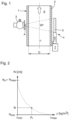
- Fig. 1 shows a schematic representation of an arrangement for the radiometric determination of the density of a medium 6, which is located in a container 1, here a pipe with a wall 2.
- the transmitting unit 3 with the gamma source and the receiving unit 4 are arranged on opposite surface areas of the pipe 1. Both components 3, 4 are connected via a Fig. 1 attached to the pipe 1 from the outside using a clamping mechanism (not shown separately).
- the encapsulation of the gamma source by the surrounding housing is designed such that the gamma radiation only exits the transmitter unit 3 in the area of the exit surface A.
- the gamma radiation radiates through the container 1 with the medium 6 located therein, the density p of which is to be determined, on the marked beam path SP.
- the gamma radiation weakened by interaction with the container wall and/or the medium 6 is received by the receiver unit 4.
- the evaluation unit 7 determines the density of the medium 6 located in the container 1.
- Corresponding radiometric density measuring arrangements are offered and sold by the applicant. As already mentioned above, the arrangement of the transmitter unit 3 and the receiver unit 4 can be designed differently with respect to the container 1.
- Fig. 2 shows a schematic representation of a graph that visualizes the dependence of the count rate N on the density p of the medium 6.
- the attenuation of the gamma radiation on the beam path SP through a medium 6 can be described using the Lambert-Beer law - i.e. it follows an e-function.
- the attenuation F corresponds to the ratio of the count rate of the gamma radiation after passing through the medium 6 to the count rate N 0 of the gamma radiation emitted by the gamma source through the exit opening A.
- the count rate N is given in counts (number of events) per second (c/sec).
- a transmitting unit 3 with a Cs137 gamma source which has a correction factor K of 95.95 ⁇ Sv ⁇ m 2 /(h ⁇ GBq), an activity P of 0.13 GBq and an isotope-dependent attenuation coefficient a of 0.048.
- the receiving unit 4 has a correction factor B of 1350 h/(s ⁇ Sv).
Landscapes
- Physics & Mathematics (AREA)
- General Physics & Mathematics (AREA)
- General Health & Medical Sciences (AREA)
- Chemical & Material Sciences (AREA)
- Analytical Chemistry (AREA)
- Biochemistry (AREA)
- Life Sciences & Earth Sciences (AREA)
- Health & Medical Sciences (AREA)
- Immunology (AREA)
- Pathology (AREA)
- Electromagnetism (AREA)
- Fluid Mechanics (AREA)
- Thermal Sciences (AREA)
- Analysing Materials By The Use Of Radiation (AREA)
- Measurement Of Radiation (AREA)
Claims (7)
- Procédé relatif à l'étalonnage d'un dispositif radiométrique destiné à la détermination et/ou à la surveillance de la densité d'un produit (6) se trouvant dans un réservoir (1), une unité d'émission (3) et une unité de réception (4) étant prévues, l'unité d'émission (3) émettant un rayonnement radioactif d'une intensité prédéfinie et l'unité de réception (4) recevant le rayonnement radioactif émis par l'unité d'émission (3) après son passage à travers le produit (6), et une unité de régulation/d'évaluation (7) étant prévue, laquelle unité détermine la densité du produit (6) se trouvant dans le réservoir (1) à l'aide de l'intensité mesurée par l'unité de réception (4), lequel procédé comprend les étapes suivantes :• Détermination du taux de comptage N0 du rayonnement radioactif après son passage à travers le réservoir (1) vide à l'aide de l'activité de l'unité d'émission (3),• Détermination du taux de comptage mesuré N du rayonnement radioactif après son passage à travers le réservoir (1) lorsqu'un produit d'étalonnage de densité connue se trouve dans le réservoir (1),• Détermination du coefficient d'atténuation de masse (µ) selon la formule µ = -(In(N/N0))/(ρ1D) avec D : chemin du faisceau de rayonnement radioactif ou diamètre intérieur du réservoir (1), ρ1 : densité du produit d'étalonnage,• Calcul d'une courbe d'étalonnage qui représente la dépendance de la densité du produit par rapport au taux de comptage de l'intensité de rayonnement mesurée après passage à travers le réservoir (1),caractérisé en ce que la détermination du taux de comptage N0 est effectuée à partir d'un calcul du taux de dose de l'unité de réception lorsque le réservoir est vide, en utilisant l'activité de l'unité d'émission.
- Procédé selon la revendication 1,
pour lequel le taux de comptage N0 du rayonnement radioactif après passage à travers le réservoir (1) vide est déterminé selon la formule N0 = (P · K · B) / (Fa · Fs), avec Fa : facteur de distance quadratique entre l'unité d'émission (3) et l'unité de réception (4), Fs : facteur d'atténuation qui dépend au moins de la paroi (2) du réservoir (1) et de l'isotope de l'unité d'émission (3), P : activité de l'unité d'émission (3), K : facteur de correction dépendant de l'isotope, B : facteur de correction pour la conversion du taux d'impulsions en taux de comptage N0. - Procédé selon la revendication 1 ou 2,
pour lequel on utilise de l'eau comme produit d'étalonnage. - Procédé selon la revendication 1, 2 ou 3,
pour lequel l'unité d'émission (3) et l'unité de réception (4) sont positionnées l'une par rapport à l'autre de telle sorte que le réservoir (1) est traversé par un rayonnement perpendiculaire à l'axe longitudinal du réservoir (1), oblique par rapport à l'axe longitudinal du réservoir (1) ou parallèle à l'axe longitudinal du réservoir (1). - Procédé selon au moins l'une des revendications précédentes,pour lequel on utilise comme réservoir (1) une conduite, etpour lequel l'unité d'émission (3) et l'unité de réception (4) sont fixées sur des zones de surface opposées de la conduite.
- Procédé selon la revendication 4 ou 5,
pour lequel l'unité de réception (4) est conçue et positionnée de manière à ce que les composants sensibles (5) de l'unité de réception (4) soient touchés par le rayonnement. - Procédé selon au moins l'une des revendications précédentes,
pour lequel le facteur d'atténuation Fs est calculé selon la formule Fs = ea·q avec a : coefficient d'atténuation dépendant de l'isotope, q : épaisseur de la paroi (2) du réservoir (1) mesurée en équivalent acier, un équivalent acier étant défini comme une densité de la paroi (2) du réservoir (1) par rapport à une densité d'acier.
Applications Claiming Priority (1)
| Application Number | Priority Date | Filing Date | Title |
|---|---|---|---|
| DE102021108307.9A DE102021108307B3 (de) | 2021-04-01 | 2021-04-01 | Verfahren zum Kalibrieren einer radiometrischen Dichte-Messvorrichtung |
Publications (3)
| Publication Number | Publication Date |
|---|---|
| EP4067863A2 EP4067863A2 (fr) | 2022-10-05 |
| EP4067863A3 EP4067863A3 (fr) | 2022-10-12 |
| EP4067863B1 true EP4067863B1 (fr) | 2024-11-20 |
Family
ID=80928984
Family Applications (1)
| Application Number | Title | Priority Date | Filing Date |
|---|---|---|---|
| EP22163168.2A Active EP4067863B1 (fr) | 2021-04-01 | 2022-03-21 | Procédé d'étalonnage d'un dispositif de mesure radiométrique de densité |
Country Status (4)
| Country | Link |
|---|---|
| US (1) | US11913969B2 (fr) |
| EP (1) | EP4067863B1 (fr) |
| CN (1) | CN115201061B (fr) |
| DE (1) | DE102021108307B3 (fr) |
Families Citing this family (1)
| Publication number | Priority date | Publication date | Assignee | Title |
|---|---|---|---|---|
| CN117871329B (zh) * | 2024-03-13 | 2024-05-24 | 南京愚工智能技术有限公司 | 一种密度在线监测装置及监测方法 |
Family Cites Families (7)
| Publication number | Priority date | Publication date | Assignee | Title |
|---|---|---|---|---|
| EP0879410A1 (fr) * | 1996-02-07 | 1998-11-25 | Biotraces, Inc. | Procede et appareil de telemesure de densite |
| GB2381862A (en) * | 2001-11-10 | 2003-05-14 | Schlumberger Holdings | Fluid density measurement |
| US7986766B2 (en) | 2008-09-30 | 2011-07-26 | Ohmart/Vega Corporation | Single well nuclear density gauge |
| DE102013105486B4 (de) * | 2013-05-28 | 2024-08-22 | Endress+Hauser SE+Co. KG | Vorrichtung zur Bestimmung und/oder Überwachung der Dichte und/oder des Füllstands eines Mediums in einem Behälter |
| CN104166153B (zh) * | 2014-07-25 | 2016-08-24 | 北京永新医疗设备有限公司 | 放射性物质辐射剂量率的二维角度分布的测量方法和设备 |
| DE102017130534B4 (de) | 2017-12-19 | 2020-12-03 | Endress+Hauser SE+Co. KG | Verfahren zum Kalibrieren einer radiometrischen Dichte-Messvorrichtung |
| CA2992330C (fr) * | 2018-01-19 | 2019-12-31 | Syncrude Canada Ltd. | Etalonnage d'appareils de mesure de densite nucleaire |
-
2021
- 2021-04-01 DE DE102021108307.9A patent/DE102021108307B3/de active Active
- 2021-06-28 US US17/360,136 patent/US11913969B2/en active Active
-
2022
- 2022-03-21 EP EP22163168.2A patent/EP4067863B1/fr active Active
- 2022-03-31 CN CN202210332374.8A patent/CN115201061B/zh active Active
Also Published As
| Publication number | Publication date |
|---|---|
| US20220317007A1 (en) | 2022-10-06 |
| CN115201061B (zh) | 2026-03-20 |
| CN115201061A (zh) | 2022-10-18 |
| EP4067863A2 (fr) | 2022-10-05 |
| DE102021108307B3 (de) | 2022-08-04 |
| US11913969B2 (en) | 2024-02-27 |
| EP4067863A3 (fr) | 2022-10-12 |
Similar Documents
| Publication | Publication Date | Title |
|---|---|---|
| EP1314006B2 (fr) | Dispositif pour determiner et/ou controler le niveau d'un materiau de remplissage dans un reservoir | |
| DE102017130534B4 (de) | Verfahren zum Kalibrieren einer radiometrischen Dichte-Messvorrichtung | |
| DE68920568T2 (de) | Vorrichtung zur Messung von Erdformationen mit hoher räumlicher Auflösung. | |
| DE102011080549B4 (de) | Optimale Detektorposition für einen Gamma-Rückstrahler | |
| DE2600812C3 (de) | Verfahren zum Bestimmen der Dichte einer geologischen Formation | |
| EP2596341B1 (fr) | Analyse par activation neutronique avec porte-échantillon standardisé pour la détermination du flux de neutrons | |
| DE2358237C2 (de) | Verfahren zur Bestimmung des Gehalts an mindestens einem chemischen Element in einer Substanz, insbesondere zur Bestimmung des Schwefelgehalts in Kohlenwasserstoff-Brennstoffen | |
| DE102012105922A1 (de) | Radiometrische Messanordnung und Verfahren zur Detektion von Ansatzbildung in einer radiometrischen Messanordnung | |
| EP4067863B1 (fr) | Procédé d'étalonnage d'un dispositif de mesure radiométrique de densité | |
| DE69123337T2 (de) | Vorrichtung zur messung des gehaltes von verschiedenen schüttgutkomponenten mit pulsierender neutronenstrahlung und verfahren zur bestimmung des gehaltes mit dieser vorrichtung | |
| DE3035929C2 (de) | Vorrichtung zur Ermittlung der Volumenanteile eines Mehrkomponentengemisches durch Transmission mehrerer Gammalinien | |
| DE2916238A1 (de) | Verfahren und vorrichtung zur analyse einer oel und wasser enthaltenden, durch eine rohrleitung stroemenden fluessigkeit zur bestimmung des wasseranteils, sowie ggf. des salzgehalts des wassers in der fluessigkeit | |
| DE3872208T2 (de) | Verfahren und vorrichtung zur messung der radioaktivitaet. | |
| DE3530090A1 (de) | Verfahren und vorrichtung zum bestimmen der eigenschaften von nassdampf | |
| DE1773085C3 (de) | Verfahren zum Messen des Füllstoffgehalts in Papier | |
| DE2916258A1 (de) | Verfahren und vorrichtung zur analyse eines fluessigkeit und gas enthaltenden, durch eine rohrleitung stroemenden mediums zur bestimmung des wasser- und oelanteils des mediums | |
| EP2217946B1 (fr) | Dispositif pour la détermination en ligne du contenu d'une substance et procédé utilisant un tel dispositif | |
| DE102016222298A1 (de) | Radiometrische Füllstandmessung | |
| DE19711124C2 (de) | Verfahren und Vorrichtung zur Erkennung künstlicher Gammastrahlung | |
| DE69705244T2 (de) | Verfahren zur bestimmung des dichteprofils | |
| EP3922986B1 (fr) | Procédé de mesure de taux de comptage ou de grandeurs mesurées en fonction des taux de comptage et dispositif de mesure de taux de comptage ou de grandeurs mesurées en fonction des taux de comptage | |
| EP1526376A1 (fr) | Méthode et appareil pour déterminer une masse surfacique et/ou une composition chimique d'un échantillon de matériau transporté | |
| EP3561459B1 (fr) | Dispositif et procédé de mesure du niveau de remplissage ou de la densité d'un milieu à l'aide de muons | |
| DE102005016792A1 (de) | Vereinfachtes Verfahren zur Sr90-Aktivitätsbestimmung | |
| WO2004086006A1 (fr) | Procede et dispositif pour determiner la teneur en solides dans une suspension |
Legal Events
| Date | Code | Title | Description |
|---|---|---|---|
| PUAI | Public reference made under article 153(3) epc to a published international application that has entered the european phase |
Free format text: ORIGINAL CODE: 0009012 |
|
| STAA | Information on the status of an ep patent application or granted ep patent |
Free format text: STATUS: THE APPLICATION HAS BEEN PUBLISHED |
|
| PUAL | Search report despatched |
Free format text: ORIGINAL CODE: 0009013 |
|
| STAA | Information on the status of an ep patent application or granted ep patent |
Free format text: STATUS: REQUEST FOR EXAMINATION WAS MADE |
|
| AK | Designated contracting states |
Kind code of ref document: A2 Designated state(s): AL AT BE BG CH CY CZ DE DK EE ES FI FR GB GR HR HU IE IS IT LI LT LU LV MC MK MT NL NO PL PT RO RS SE SI SK SM TR |
|
| AK | Designated contracting states |
Kind code of ref document: A3 Designated state(s): AL AT BE BG CH CY CZ DE DK EE ES FI FR GB GR HR HU IE IS IT LI LT LU LV MC MK MT NL NO PL PT RO RS SE SI SK SM TR |
|
| RIC1 | Information provided on ipc code assigned before grant |
Ipc: G01N 9/24 20060101AFI20220905BHEP |
|
| 17P | Request for examination filed |
Effective date: 20220913 |
|
| RBV | Designated contracting states (corrected) |
Designated state(s): AL AT BE BG CH CY CZ DE DK EE ES FI FR GB GR HR HU IE IS IT LI LT LU LV MC MK MT NL NO PL PT RO RS SE SI SK SM TR |
|
| GRAP | Despatch of communication of intention to grant a patent |
Free format text: ORIGINAL CODE: EPIDOSNIGR1 |
|
| STAA | Information on the status of an ep patent application or granted ep patent |
Free format text: STATUS: GRANT OF PATENT IS INTENDED |
|
| INTG | Intention to grant announced |
Effective date: 20240711 |
|
| GRAS | Grant fee paid |
Free format text: ORIGINAL CODE: EPIDOSNIGR3 |
|
| GRAA | (expected) grant |
Free format text: ORIGINAL CODE: 0009210 |
|
| STAA | Information on the status of an ep patent application or granted ep patent |
Free format text: STATUS: THE PATENT HAS BEEN GRANTED |
|
| AK | Designated contracting states |
Kind code of ref document: B1 Designated state(s): AL AT BE BG CH CY CZ DE DK EE ES FI FR GB GR HR HU IE IS IT LI LT LU LV MC MK MT NL NO PL PT RO RS SE SI SK SM TR |
|
| REG | Reference to a national code |
Ref country code: GB Ref legal event code: FG4D Free format text: NOT ENGLISH |
|
| REG | Reference to a national code |
Ref country code: CH Ref legal event code: EP |
|
| REG | Reference to a national code |
Ref country code: DE Ref legal event code: R096 Ref document number: 502022002146 Country of ref document: DE |
|
| REG | Reference to a national code |
Ref country code: IE Ref legal event code: FG4D Free format text: LANGUAGE OF EP DOCUMENT: GERMAN |
|
| P01 | Opt-out of the competence of the unified patent court (upc) registered |
Free format text: CASE NUMBER: APP_6799/2025 Effective date: 20250210 |
|
| REG | Reference to a national code |
Ref country code: LT Ref legal event code: MG9D |
|
| REG | Reference to a national code |
Ref country code: NL Ref legal event code: MP Effective date: 20241120 |
|
| PG25 | Lapsed in a contracting state [announced via postgrant information from national office to epo] |
Ref country code: HR Free format text: LAPSE BECAUSE OF FAILURE TO SUBMIT A TRANSLATION OF THE DESCRIPTION OR TO PAY THE FEE WITHIN THE PRESCRIBED TIME-LIMIT Effective date: 20241120 Ref country code: PT Free format text: LAPSE BECAUSE OF FAILURE TO SUBMIT A TRANSLATION OF THE DESCRIPTION OR TO PAY THE FEE WITHIN THE PRESCRIBED TIME-LIMIT Effective date: 20250320 Ref country code: IS Free format text: LAPSE BECAUSE OF FAILURE TO SUBMIT A TRANSLATION OF THE DESCRIPTION OR TO PAY THE FEE WITHIN THE PRESCRIBED TIME-LIMIT Effective date: 20250320 |
|
| PG25 | Lapsed in a contracting state [announced via postgrant information from national office to epo] |
Ref country code: FI Free format text: LAPSE BECAUSE OF FAILURE TO SUBMIT A TRANSLATION OF THE DESCRIPTION OR TO PAY THE FEE WITHIN THE PRESCRIBED TIME-LIMIT Effective date: 20241120 Ref country code: NL Free format text: LAPSE BECAUSE OF FAILURE TO SUBMIT A TRANSLATION OF THE DESCRIPTION OR TO PAY THE FEE WITHIN THE PRESCRIBED TIME-LIMIT Effective date: 20241120 |
|
| PG25 | Lapsed in a contracting state [announced via postgrant information from national office to epo] |
Ref country code: BG Free format text: LAPSE BECAUSE OF FAILURE TO SUBMIT A TRANSLATION OF THE DESCRIPTION OR TO PAY THE FEE WITHIN THE PRESCRIBED TIME-LIMIT Effective date: 20241120 |
|
| PG25 | Lapsed in a contracting state [announced via postgrant information from national office to epo] |
Ref country code: ES Free format text: LAPSE BECAUSE OF FAILURE TO SUBMIT A TRANSLATION OF THE DESCRIPTION OR TO PAY THE FEE WITHIN THE PRESCRIBED TIME-LIMIT Effective date: 20241120 |
|
| PG25 | Lapsed in a contracting state [announced via postgrant information from national office to epo] |
Ref country code: NO Free format text: LAPSE BECAUSE OF FAILURE TO SUBMIT A TRANSLATION OF THE DESCRIPTION OR TO PAY THE FEE WITHIN THE PRESCRIBED TIME-LIMIT Effective date: 20250220 |
|
| PG25 | Lapsed in a contracting state [announced via postgrant information from national office to epo] |
Ref country code: LV Free format text: LAPSE BECAUSE OF FAILURE TO SUBMIT A TRANSLATION OF THE DESCRIPTION OR TO PAY THE FEE WITHIN THE PRESCRIBED TIME-LIMIT Effective date: 20241120 Ref country code: GR Free format text: LAPSE BECAUSE OF FAILURE TO SUBMIT A TRANSLATION OF THE DESCRIPTION OR TO PAY THE FEE WITHIN THE PRESCRIBED TIME-LIMIT Effective date: 20250221 |
|
| PG25 | Lapsed in a contracting state [announced via postgrant information from national office to epo] |
Ref country code: PL Free format text: LAPSE BECAUSE OF FAILURE TO SUBMIT A TRANSLATION OF THE DESCRIPTION OR TO PAY THE FEE WITHIN THE PRESCRIBED TIME-LIMIT Effective date: 20241120 |
|
| PG25 | Lapsed in a contracting state [announced via postgrant information from national office to epo] |
Ref country code: RS Free format text: LAPSE BECAUSE OF FAILURE TO SUBMIT A TRANSLATION OF THE DESCRIPTION OR TO PAY THE FEE WITHIN THE PRESCRIBED TIME-LIMIT Effective date: 20250220 |
|
| PG25 | Lapsed in a contracting state [announced via postgrant information from national office to epo] |
Ref country code: SM Free format text: LAPSE BECAUSE OF FAILURE TO SUBMIT A TRANSLATION OF THE DESCRIPTION OR TO PAY THE FEE WITHIN THE PRESCRIBED TIME-LIMIT Effective date: 20241120 |
|
| PG25 | Lapsed in a contracting state [announced via postgrant information from national office to epo] |
Ref country code: DK Free format text: LAPSE BECAUSE OF FAILURE TO SUBMIT A TRANSLATION OF THE DESCRIPTION OR TO PAY THE FEE WITHIN THE PRESCRIBED TIME-LIMIT Effective date: 20241120 |
|
| PG25 | Lapsed in a contracting state [announced via postgrant information from national office to epo] |
Ref country code: EE Free format text: LAPSE BECAUSE OF FAILURE TO SUBMIT A TRANSLATION OF THE DESCRIPTION OR TO PAY THE FEE WITHIN THE PRESCRIBED TIME-LIMIT Effective date: 20241120 |
|
| PG25 | Lapsed in a contracting state [announced via postgrant information from national office to epo] |
Ref country code: RO Free format text: LAPSE BECAUSE OF FAILURE TO SUBMIT A TRANSLATION OF THE DESCRIPTION OR TO PAY THE FEE WITHIN THE PRESCRIBED TIME-LIMIT Effective date: 20241120 |
|
| PG25 | Lapsed in a contracting state [announced via postgrant information from national office to epo] |
Ref country code: SK Free format text: LAPSE BECAUSE OF FAILURE TO SUBMIT A TRANSLATION OF THE DESCRIPTION OR TO PAY THE FEE WITHIN THE PRESCRIBED TIME-LIMIT Effective date: 20241120 |
|
| PG25 | Lapsed in a contracting state [announced via postgrant information from national office to epo] |
Ref country code: CZ Free format text: LAPSE BECAUSE OF FAILURE TO SUBMIT A TRANSLATION OF THE DESCRIPTION OR TO PAY THE FEE WITHIN THE PRESCRIBED TIME-LIMIT Effective date: 20241120 |
|
| REG | Reference to a national code |
Ref country code: DE Ref legal event code: R097 Ref document number: 502022002146 Country of ref document: DE |
|
| PG25 | Lapsed in a contracting state [announced via postgrant information from national office to epo] |
Ref country code: SE Free format text: LAPSE BECAUSE OF FAILURE TO SUBMIT A TRANSLATION OF THE DESCRIPTION OR TO PAY THE FEE WITHIN THE PRESCRIBED TIME-LIMIT Effective date: 20241120 |
|
| PLBE | No opposition filed within time limit |
Free format text: ORIGINAL CODE: 0009261 |
|
| STAA | Information on the status of an ep patent application or granted ep patent |
Free format text: STATUS: NO OPPOSITION FILED WITHIN TIME LIMIT |
|
| PG25 | Lapsed in a contracting state [announced via postgrant information from national office to epo] |
Ref country code: MC Free format text: LAPSE BECAUSE OF FAILURE TO SUBMIT A TRANSLATION OF THE DESCRIPTION OR TO PAY THE FEE WITHIN THE PRESCRIBED TIME-LIMIT Effective date: 20241120 |
|
| 26N | No opposition filed |
Effective date: 20250821 |
|
| REG | Reference to a national code |
Ref country code: CH Ref legal event code: H13 Free format text: ST27 STATUS EVENT CODE: U-0-0-H10-H13 (AS PROVIDED BY THE NATIONAL OFFICE) Effective date: 20251023 |
|
| PG25 | Lapsed in a contracting state [announced via postgrant information from national office to epo] |
Ref country code: LU Free format text: LAPSE BECAUSE OF NON-PAYMENT OF DUE FEES Effective date: 20250321 |
|
| REG | Reference to a national code |
Ref country code: BE Ref legal event code: MM Effective date: 20250331 |
|
| PG25 | Lapsed in a contracting state [announced via postgrant information from national office to epo] |
Ref country code: BE Free format text: LAPSE BECAUSE OF NON-PAYMENT OF DUE FEES Effective date: 20250331 |
|
| PG25 | Lapsed in a contracting state [announced via postgrant information from national office to epo] |
Ref country code: CH Free format text: LAPSE BECAUSE OF NON-PAYMENT OF DUE FEES Effective date: 20250331 |
|
| PG25 | Lapsed in a contracting state [announced via postgrant information from national office to epo] |
Ref country code: IE Free format text: LAPSE BECAUSE OF NON-PAYMENT OF DUE FEES Effective date: 20250321 |
|
| PGFP | Annual fee paid to national office [announced via postgrant information from national office to epo] |
Ref country code: DE Payment date: 20260319 Year of fee payment: 5 |
|
| PGFP | Annual fee paid to national office [announced via postgrant information from national office to epo] |
Ref country code: AT Payment date: 20260301 Year of fee payment: 5 |
|
| PGFP | Annual fee paid to national office [announced via postgrant information from national office to epo] |
Ref country code: IT Payment date: 20260324 Year of fee payment: 5 |
|
| PGFP | Annual fee paid to national office [announced via postgrant information from national office to epo] |
Ref country code: FR Payment date: 20260323 Year of fee payment: 5 |