EP4067911B1 - Vorhersage des ausfalls und schätzung der verbleibenden lebensdauer einer luft-daten-sonden-heizung - Google Patents
Vorhersage des ausfalls und schätzung der verbleibenden lebensdauer einer luft-daten-sonden-heizung Download PDFInfo
- Publication number
- EP4067911B1 EP4067911B1 EP22155691.3A EP22155691A EP4067911B1 EP 4067911 B1 EP4067911 B1 EP 4067911B1 EP 22155691 A EP22155691 A EP 22155691A EP 4067911 B1 EP4067911 B1 EP 4067911B1
- Authority
- EP
- European Patent Office
- Prior art keywords
- heating element
- resistive heating
- remaining
- electrical
- frequency components
- Prior art date
- Legal status (The legal status is an assumption and is not a legal conclusion. Google has not performed a legal analysis and makes no representation as to the accuracy of the status listed.)
- Active
Links
Images




Classifications
-
- G—PHYSICS
- G01—MEASURING; TESTING
- G01P—MEASURING LINEAR OR ANGULAR SPEED, ACCELERATION, DECELERATION, OR SHOCK; INDICATING PRESENCE, ABSENCE, OR DIRECTION, OF MOVEMENT
- G01P21/00—Testing or calibrating of apparatus or devices covered by the preceding groups
- G01P21/02—Testing or calibrating of apparatus or devices covered by the preceding groups of speedometers
- G01P21/025—Testing or calibrating of apparatus or devices covered by the preceding groups of speedometers for measuring speed of fluids; for measuring speed of bodies relative to fluids
-
- G—PHYSICS
- G01—MEASURING; TESTING
- G01R—MEASURING ELECTRIC VARIABLES; MEASURING MAGNETIC VARIABLES
- G01R31/00—Arrangements for testing electric properties; Arrangements for locating electric faults; Arrangements for electrical testing characterised by what is being tested not provided for elsewhere
- G01R31/50—Testing of electric apparatus, lines, cables or components for short-circuits, continuity, leakage current or incorrect line connections
- G01R31/56—Testing of electric apparatus
-
- G—PHYSICS
- G01—MEASURING; TESTING
- G01P—MEASURING LINEAR OR ANGULAR SPEED, ACCELERATION, DECELERATION, OR SHOCK; INDICATING PRESENCE, ABSENCE, OR DIRECTION, OF MOVEMENT
- G01P13/00—Indicating or recording presence, absence, or direction, of movement
- G01P13/02—Indicating direction only, e.g. by weather vane
- G01P13/025—Indicating direction only, e.g. by weather vane indicating air data, i.e. flight variables of an aircraft, e.g. angle of attack, side slip, shear, yaw
-
- G—PHYSICS
- G01—MEASURING; TESTING
- G01P—MEASURING LINEAR OR ANGULAR SPEED, ACCELERATION, DECELERATION, OR SHOCK; INDICATING PRESENCE, ABSENCE, OR DIRECTION, OF MOVEMENT
- G01P5/00—Measuring speed of fluids, e.g. of air stream; Measuring speed of bodies relative to fluids, e.g. of ship, of aircraft
- G01P5/14—Measuring speed of fluids, e.g. of air stream; Measuring speed of bodies relative to fluids, e.g. of ship, of aircraft by measuring differences of pressure in the fluid
-
- G—PHYSICS
- G01—MEASURING; TESTING
- G01P—MEASURING LINEAR OR ANGULAR SPEED, ACCELERATION, DECELERATION, OR SHOCK; INDICATING PRESENCE, ABSENCE, OR DIRECTION, OF MOVEMENT
- G01P5/00—Measuring speed of fluids, e.g. of air stream; Measuring speed of bodies relative to fluids, e.g. of ship, of aircraft
- G01P5/14—Measuring speed of fluids, e.g. of air stream; Measuring speed of bodies relative to fluids, e.g. of ship, of aircraft by measuring differences of pressure in the fluid
- G01P5/16—Measuring speed of fluids, e.g. of air stream; Measuring speed of bodies relative to fluids, e.g. of ship, of aircraft by measuring differences of pressure in the fluid using Pitot tubes, e.g. Machmeter
- G01P5/165—Arrangements or constructions of Pitot tubes
-
- G—PHYSICS
- G01—MEASURING; TESTING
- G01R—MEASURING ELECTRIC VARIABLES; MEASURING MAGNETIC VARIABLES
- G01R31/00—Arrangements for testing electric properties; Arrangements for locating electric faults; Arrangements for electrical testing characterised by what is being tested not provided for elsewhere
- G01R31/50—Testing of electric apparatus, lines, cables or components for short-circuits, continuity, leakage current or incorrect line connections
- G01R31/52—Testing for short-circuits, leakage current or ground faults
-
- H—ELECTRICITY
- H05—ELECTRIC TECHNIQUES NOT OTHERWISE PROVIDED FOR
- H05B—ELECTRIC HEATING; ELECTRIC LIGHT SOURCES NOT OTHERWISE PROVIDED FOR; CIRCUIT ARRANGEMENTS FOR ELECTRIC LIGHT SOURCES, IN GENERAL
- H05B3/00—Ohmic-resistance heating
- H05B3/84—Heating arrangements specially adapted for transparent or reflecting areas, e.g. for demisting or de-icing windows, mirrors or vehicle windshields
- H05B3/86—Heating arrangements specially adapted for transparent or reflecting areas, e.g. for demisting or de-icing windows, mirrors or vehicle windshields the heating conductors being embedded in the transparent or reflecting material
-
- B—PERFORMING OPERATIONS; TRANSPORTING
- B64—AIRCRAFT; AVIATION; COSMONAUTICS
- B64D—EQUIPMENT FOR FITTING IN OR TO AIRCRAFT; FLIGHT SUITS; PARACHUTES; ARRANGEMENT OR MOUNTING OF POWER PLANTS OR PROPULSION TRANSMISSIONS IN AIRCRAFT
- B64D15/00—De-icing or preventing icing on exterior surfaces of aircraft
- B64D15/12—De-icing or preventing icing on exterior surfaces of aircraft by electric heating
-
- B—PERFORMING OPERATIONS; TRANSPORTING
- B64—AIRCRAFT; AVIATION; COSMONAUTICS
- B64D—EQUIPMENT FOR FITTING IN OR TO AIRCRAFT; FLIGHT SUITS; PARACHUTES; ARRANGEMENT OR MOUNTING OF POWER PLANTS OR PROPULSION TRANSMISSIONS IN AIRCRAFT
- B64D45/00—Aircraft indicators or protectors not otherwise provided for
- B64D2045/0085—Devices for aircraft health monitoring, e.g. monitoring flutter or vibration
-
- B—PERFORMING OPERATIONS; TRANSPORTING
- B64—AIRCRAFT; AVIATION; COSMONAUTICS
- B64D—EQUIPMENT FOR FITTING IN OR TO AIRCRAFT; FLIGHT SUITS; PARACHUTES; ARRANGEMENT OR MOUNTING OF POWER PLANTS OR PROPULSION TRANSMISSIONS IN AIRCRAFT
- B64D43/00—Arrangements or adaptations of instruments
- B64D43/02—Arrangements or adaptations of instruments for indicating aircraft speed or stalling conditions
-
- G—PHYSICS
- G01—MEASURING; TESTING
- G01P—MEASURING LINEAR OR ANGULAR SPEED, ACCELERATION, DECELERATION, OR SHOCK; INDICATING PRESENCE, ABSENCE, OR DIRECTION, OF MOVEMENT
- G01P5/00—Measuring speed of fluids, e.g. of air stream; Measuring speed of bodies relative to fluids, e.g. of ship, of aircraft
- G01P5/14—Measuring speed of fluids, e.g. of air stream; Measuring speed of bodies relative to fluids, e.g. of ship, of aircraft by measuring differences of pressure in the fluid
- G01P5/16—Measuring speed of fluids, e.g. of air stream; Measuring speed of bodies relative to fluids, e.g. of ship, of aircraft by measuring differences of pressure in the fluid using Pitot tubes, e.g. Machmeter
Definitions
- Air data probes typically include resistive heater elements to prevent operational issues relating to in-flight ice buildup.
- One of the most common types of failures in air data probes is failure of the resistive heating element. The ability to predict a future failure of the resistive heating element in air data probes would permit and facilitate pre-emptive maintenance to be performed without causing flight delays.
- the heater element in an air data probe often consists of a resistive heater wire surrounded by an insulator and encapsulated within a metallic sheath.
- the insulator creates a very high electrical resistance between the metallic sheath (often electrically connected to the body of the probe) and the heater wire itself.
- the presence of the heater wire, insulator, and metallic sheath also creates a capacitance between the sheath and the heater wire.
- the combination of the insulation resistance and the wire-sheath capacitance creates a path for leakage current to flow from the heater wire to the sheath when a voltage is applied to the heating element.
- US 2020/191850 A1 discloses a system for predicting remaining useful life of a resistive heating element.
- US 2020/391871 A1 discloses a system for monitoring health of an electrical heater of an air data probe.
- US 2018/275183 A1 discloses a system for determining remaining useful life of a probe system.
- a system for predicting failure of a resistive heating element of an air data probe is provided according to claim 1.
- a method for predicting failure of a resistive heating element of an air data probe is provided according to claim 7.
- Apparatus and associated methods relate to predicting failure and estimating remaining useful life of a resistive heating element of an air-data-probe heater by sensing electrical current provided to the resistive heating element.
- FIG. 1 is a schematic diagram of an aircraft equipped with a system for predicting failure and/or estimating remaining useful life of an air-data-probe heater.
- aircraft 10 includes engine 12, which drives electrical generator 14 so as to provide electrical operating power to various powered electrical systems aboard aircraft 10.
- Aircraft 10 is also equipped with various air-data-probe sensors, including air-data-probe sensor 16.
- Air-data-probe sensor 16 is an electrical system powered by aircraft power distribution system 18.
- Air-data-probe sensor 16 receives operating power from aircraft power source 18 via electrical operating power cable 20.
- Aircraft 10 is also equipped with health monitoring system 22, which predicts failure and/or estimates remaining useful life of resistive heating element 24 of air-data-probe sensor 16.
- health monitoring system 22 is configured to predict failure and/or estimate remaining useful life of resistive heating element 24 based on an electrical metric of electrical operating power provided to resistive heating element 24.
- air-data-probe sensor 16 senses air pressure.
- Various air-data-probe sensors sense air pressure for the purpose of determining various air data metrics, such as airspeed, altitude, angle-of-attack, etc.
- air-data-probe sensor 16 is a Pitot tube airspeed detector that includes resistive heating element 24, and ram pressure air-data-probe sensor 26.
- Resistive heating element 24 is configured to prevent icing of air-data-probe sensor 16 when aircraft 10 is operating in an atmosphere in which ice accretion can occur.
- Health monitoring system 22 includes electrical power source 28, electrical sensor 30, and remaining life prediction engine 32.
- Electrical power source 28 converts electrical power received from aircraft power source 18 into one or more different power configurations for use by air-data-probe sensor 16 and/or resistive heating element 24.
- Electrical sensor 30 is configured to sense an electrical metric of the operating power provided to resistive heating element 24.
- the electrical metric sensed by electrical sensor 30 is at least one of: i) phase relation between electrical current conducted from the resistive heating element to its surrounding conductive sheath and voltage across the resistive heating element; ii) a time-domain profile during a full power cycle of the leakage current conducted from the resistive heating element to its surrounding conductive sheath or the voltage across the resistive heating element; and/or iii) high-frequency components of the electrical current conducted by the resistive heating element and/or of the voltage across the resistive heating element.
- Remaining life prediction engine 32 predicts failure and/or estimates remaining useful life of resistive heating element 24 based on the electrical metric sensed by electrical sensor 30.
- Each of the various electrical metrics described above can be indicative of health of resistive heating element 24.
- Each of these described electrical metrics with be further described below along with the relation these electrical metrics have with the health of resistive heating element 24, with reference to FIGS. 2-8 .
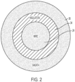
- FIG. 2 is a graph of a cross-sectional diagram of a resistive heating element along with coaxial insulative material and a coaxial conductive sheath.
- Resistive heating element 24 is designed to have a particular resistance-temperature relation.
- the temperature of resistive heating element 24 can be determined based on a determination of electrical resistance of resistive heating element 24.
- electrical resistance of resistive heating element 24 can be monotonically increasing with increasing temperature.
- temperature of resistive heating element 24 is a function of resistance of resistive heating element 24.
- Coaxial insulative material 34 provides electrical insulation between resistive heating element 24 and surrounding coaxial conductive sheath 36. Such electrical insulation permits resistive heating element 24 to be electrically biased independently of coaxial conductive sheath 36, which is typically grounded.
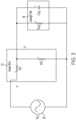
- FIG. 3 is simplified schematic circuit demonstrating leakage behavior of a resistive heating element biased by an electrical power source.
- electrical power source 28 provides operating power to resistive heating element 24.
- Resistive heating element 24 has leakage path 38 at a particular location along a length of resistive heating element 24.
- Simplified lumped parameter model of resistive heating element 24 has portions on either side of the particular location along its length, as represented by first heating resistor R H1 and second heating resistor R H2 .
- Leakage path 38 is modeled as leakage resistance R LKG in parallel with leakage capacitance C LKG .
- leakage resistance R LKG and leakage capacitance C LKG can change over time for a variety of reasons.
- coaxial insulative material 24 (depicted in FIG. 2 ) can degrade, providing increased conductivity and/or changed capacitive coupling between resistive heating element 24 and surrounding coaxial conductive sheath 36.
- These two mechanisms - increased conductivity and/or increased capacitive coupling - are represented as leakage resistor R LKG and leakage capacitor C LKG , respectively.
- the primary mechanism in response to degradation of insulative material 34 is increased conductivity (i.e., reduced leakage resistance R LKG ).
- leakage resistance R LKG decreases (e.g., due to degradation of insulative material 34)
- the character of the leakage path changes from being mostly capacitive to more resistive.
- phase angle will become less out of phase, as the coupling between resistive heating element 24 and coaxial conductive sheath 36, becomes more conductive (i.e., leakage resistance R LKG become smaller) and less capacitive.
- FIGS. 4A-4C which are not according to the present invention, are graphs of AC electrical voltage of operating power provided to a resistive heating element and leakage current, for various health conditions of a resistive heating element.
- graph 40 includes horizontal axis 42, vertical axis 44, voltage-time relation 46, and current-time relation 48.
- Horizontal axis 42 is indicative of time.
- Vertical axis 44 is indicative of voltage and leakage current.
- Voltage-time relation 46 depicts temporal behavior of voltage across resistive heating element 24 (as depicted in FIG. 3 ).
- electrical power source 28 provides AC operating power to resistive heating element 24.
- FIG. 4A graph 40 includes horizontal axis 42, vertical axis 44, voltage-time relation 46, and current-time relation 48.
- Horizontal axis 42 is indicative of time.
- Vertical axis 44 is indicative of voltage and leakage current.
- Voltage-time relation 46 depicts temporal behavior of voltage across resistive heating element 24 (as depicted in FIG. 3
- leakage current-time relation 48 is mostly out of phase with voltage-time relation 46.
- Leakage current-time relation 48 leads voltage-time relation 46 by about 90 degrees.
- Such a relation occurs when leakage capacitor C LKG is quite large as compared to the resistive path (e.g., the impedance associated with leakage capacitor C LKG is a dominant contributor to the leakage current at the frequency of the AC operating power - the insulation resistance in this case is quite large and has much smaller contribution to leakage current).
- phase relation is indicative of little or no degradation of insulative material 34.
- graph 50 includes horizontal axis 52, vertical axis 54, voltage-time relation 56, and leakage current-time relation 58.
- Horizontal axis 52 is again indicative of time.
- Vertical axis 54 is again indicative of voltage and leakage current.
- Voltage-time relation 56 depicts temporal behavior of voltage across resistive heating element 24 (as depicted in FIG. 3 ).
- electrical power source 28 provides AC operating power to resistive heating element 24.
- leakage current-time relation 58 is not in phase with voltage-time relation 56.
- Leakage current-time relation 58 leads voltage-time relation 56 by about 45 degrees. Such a relation can occur when the impedance of leakage capacitor C LKG is comparable to impedance of the leakage resistor R LKG at frequency of the AC operating power.
- phase relation is indicative of some degradation of insulative material 34.
- graph 60 includes horizontal axis 62, vertical axis 64, voltage-time relation 66, and leakage current-time relation 68.
- Horizontal axis 62 is again indicative of time.
- Vertical axis 64 is again indicative of voltage and leakage current.
- Voltage-time relation 66 depicts temporal behavior of voltage across resistive heating element 24 (as depicted in FIG. 3 ).
- electrical power source 28 provides AC operating power to resistive heating element 24.
- leakage current-time relation 48 is mostly in phase with voltage-time relation 66. Such a relation occurs when insulative material 34 becomes compromised (e.g., very thin or non-existent in places).
- Temperature also affects the phase relation of the electrical current and the voltage for a degraded resistive heating element.
- a temperature dependency can occur for a variety of reasons. For example, as resistive heating element 24 heats up, leakage conductance (i.e., inverse of R LKG ) can decrease as moisture is driven away out of coaxial insulative material 34. This decrease in leakage conductance 1/R LKG can cause the phase relation between leakage current and voltage across resistive heating element 24 to become somewhat more out of phase (e.g., between a 10 and 30 degree change from its initial cold temperature phase relation). Also, a temperature dependency can occur because the insulative quality of insulative material 34 can change as a function of temperature. Thus, understanding the normal temperature dependency of the leakage current-voltage phase relation can help one to identify when such a phase relation is abnormal.
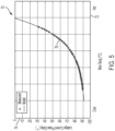
- FIG. 5 which is not according to the present invention, is a graph of leakage current to voltage phase relationship at the operating power provided to a resistive heating element as a function of temperature.
- graph 70 includes horizontal axis 72, vertical axis 74, and leakage current-voltage phase relation 76.
- Horizontal axis 72 is indicative of temperature.
- Vertical axis 74 is indicative of phase delay angle of the leakage current with regard to the voltage of the operating power provided to resistive heating element 24 (depicted in FIG. 2 ).
- Leakage current-voltage phase relation 76 indicates that at low temperatures, the electrical current is delayed by about -90 degrees (i.e., the electrical current leads the voltage by about 90 degrees).
- phase delay of the leakage current increases (i.e., decreases in negative magnitude). Such a large change in phase relation is indicative of a probe, in which insulative material 34 has been degraded.
- changes in the phase relation due to heating of resistive heating element is typically modest (e.g., between 10 and 30 degrees).
- the phase delay of the leakage current crosses zero degrees for the resistive heating element with degraded insulative material, as depicted in the figure.
- some embodiments of health monitoring system 22 use leakage current-voltage phase data acquired at a predetermined standard temperature. Other embodiments of health monitoring system 22 compare measurements of leakage current-voltage phase data with a known predetermined leakage current-voltage phase relation, such as, for example, leakage current-voltage phase relation 76.
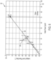
- FIG. 6 which is not according to the present invention, is a graph of leakage current phase delay data acquired over a lifetime of a resistive heating element.
- graph 80 includes horizontal axis 82, vertical axis 84, leakage current data 86 and leakage current projection 88.
- Horizontal axis 82 is indicative of heater power cycle number.
- Vertical axis 84 is indicative of leakage current phase delay. Every time that the resistive heating element 24 is power cycled (i.e., turned on and operated), data is collected at a predetermined operating temperature, as the temperature of resistive heating element 24 crosses that predetermined operating temperature. This acquired data is represented on graph 80 as leakage current data 86.
- a trend line is fit to leakage current data 86 and projected as leakage current phase delay projection 88 on graph 80.
- the number of remaining power cycles before leakage current phase delay projection 88 crosses a predetermined threshold can indicate a remaining useful life of resistive heating element 24.
- predetermined threshold is zero degrees, but such a threshold need not be zero degrees, depending on the lifetime testing margin of the particular embodiment.
- FIG. 7 which is not according to the present invention, is a graph of various start up behaviors for leakage current from a resistive heating element.
- graph 90 includes horizontal axis 92, vertical axis 94, and leakage current-time relations 96A-96C.
- Horizontal axis 92 is indicative of time measured from initial provision of power to resistive heating element 24.
- Vertical axis 94 is indicative of leakage current measured between resistive heating element 24 and coaxial conductive sheath 38.
- electrical power source 28 provides AC operating power to resistive heating element 24.
- RMS values of current and power can be monitored and start up behavior of these monitored electrical metrics are indicative of health of coaxial conductive sheath 36 and/or coaxial insulative material 34.
- An increase in leakage current exhibitions of noise fluctuations can indicate a presence of moisture, thus indicating damage to either coaxial conductive sheath 36 and/or coaxial insulative material 34.
- DC operating power is provided to resistive heating element 24.
- Such leakage current can have start-up behavior that varies in response to health condition and in response to presence or absence of moisture.
- Current-time relations 96A-96C represent leakage current of resistive heating element 24 as measured at start-up time for three consequent start-up cycles representing different moisture content conditions: i) before moisture ingress; ii) with moisture ingress; and iii) after moisture ingress.
- Coaxial conductive sheath 36 is configured to provide a physical barrier between resistive heating element 24 and coaxial insulative material 32 from the atmospheric environment. Moisture in the atmospheric environment can cause degradation to each of coaxial insulative material 32 and resistive heating element 24, should such elements be exposed to moisture in the atmosphere. The integrity of the barrier presented by coaxial conductive sheath 36 can become compromised with age, though. And should coaxial conductive sheath 36 become compromised, leakage currents can increase as a result of degradation (e.g., thinning, cracking, etc.) of coaxial insulative material 34. Such degradation can be due to a compromised coaxial conductive sheath 36, which, when compromised, can permit the ingress of moisture into coaxial insulative material 34 and resistive heating element 24.
- degradation e.g., thinning, cracking, etc.
- Current-time relation 96A represents the power-cycle leakage current profile for resistive heating element 24 before moisture ingress into coaxial insulative material 34 and/or resistive heating element 24.
- Current-time relation 96C represents the start-up leakage current profile for resistive heating element 24 after moisture ingress into coaxial insulative material 34 and/or resistive heating element 24. Such moisture ingress assists the conduction of electrical currents, thereby increasing the level of leakage current until thermal heating element 34 heats up enough to drive away the moisture present.
- the steady-state current asymptote is higher for current-time relation 96C than the steady-state current asymptote for current-time relation 96A.
- Current-time relation 96B represents the power-cycle leakage current profile for resistive heating element 24 after moisture ingress into coaxial insulative material 34 and/or resistive heating element 24 (e.g., after the moisture has been driven out of coaxial insulative material 34 by temperatures generated by resistive heating element 24).
- the steady-state current asymptote remains higher for current-time relation 96B than the steady-state current asymptote for current-time relation 96A.
- FIG. 8 is a graph of high-frequency noise in AC electrical currents provided to a resistive heating element showing degradation.
- graph 100 includes horizontal axis 102, vertical axis 104, and electrical current-time relations 106 and 108.
- Horizontal axis 102 is indicative of time.
- Vertical axis 104 is indicative of amplitude of electrical current of operating power provided to resistive heating element 24.
- Electrical current-time relation 106 depicts temporal behavior of electrical current of the operating power provided to resistive heating element 24 (as depicted in FIG.
- electrical current-time relation 108 depicts temporal behavior of electrical current of the operating power provided to resistive heating element 24 (as depicted in FIG. 3 ), for a resistive heating element with degraded insulative material 34.
- the main difference between electrical current-time relation 106 and electrical current-time relation 108 is the high-frequency behavior (i.e., at frequencies high in comparison with the frequency of the AC operating power).
- Electrical current-time relation 108 has discernable high-frequency noise superimposed on the AC signal, whereas electrical current-time relation 106 has no discernable high-frequency noise. Such high-frequency noise can be indicative of a corroded resistive heating element 24.
- Current-time relation 108 has such high-frequency components indicative of degradation (e.g., micro cracks) of resistive heating element 24 superimposed on the AC current waveform.
- High-frequency components in current-time relation 108 can be caused by other factors as well. For example, any high-frequency components in voltage of the operating power provided to resistive heating element 24 will be replicated in current-time relation 106 for resistive heating element 34 that are not degraded. Therefore, sensing high-frequency components of both voltage-time relation 106 and current-time relation 108 can be used to determine if such components are present in but one of the two electrical metrics. For example, a ratio can be made of the high-frequency components of current-time relation 108 to the high-frequency components of voltage of operating power provided to resistive heating element 24. Then, such a ratio can be compared with a predetermined threshold value. If the ratio is greater than the predetermined threshold value, remaining life prediction engine 32 can generate a signal indicative of the event. A log of such incidences of such a comparison can be maintained. Remaining useful life can be determined based on such a log.
- Such high-frequency components are sensed by taking a derivative of voltage of operating power provided to resistive heating element 24 and/or current-time relation 108.
- the operation of taking the derivative amplifies high-frequency components above lower-frequency components.
- a ratio of the derivatives of the current-time relation and the voltage-time relation can then be compared with a predetermined threshold. If the ratio is greater than the predetermined threshold, such a comparison can be indicative of micro cracks in resistive heating element 24.
- Remaining life prediction engine 32 can make such calculations (e.g., take the derivatives, calculate the ratio, and make the comparison, etc.) in various ways.
- remaining life prediction engine 32 can include a processor, a programmable logic array, or any other type of programmable device. In some embodiments, remaining life prediction engine 32 can be configured to perform all of the operations using discrete circuitry.
Landscapes
- Physics & Mathematics (AREA)
- General Physics & Mathematics (AREA)
- Engineering & Computer Science (AREA)
- Aviation & Aerospace Engineering (AREA)
- Power Engineering (AREA)
- Testing Electric Properties And Detecting Electric Faults (AREA)
- Testing Of Short-Circuits, Discontinuities, Leakage, Or Incorrect Line Connections (AREA)
Claims (13)
- System (22) zum Vorhersagen eines Ausfalls eines Widerstandsheizelements einer Luft-Daten-Sonde, wobei das System umfasst:eine elektrische Wechselstrom-Leistungsquelle (28), die dazu konfiguriert ist, dem Widerstandsheizelement (24) elektrische Wechselstrom-Betriebsleistung bereitzustellen;einen elektrischen Sensor (30), der dazu konfiguriert ist, den elektrischen Strom zum Widerstandsheizelement zu erfassen;einen Hochfrequenzsignaldetektor, der dazu konfiguriert ist, Hochfrequenzkomponenten des erfassten elektrischen Stroms durch Ableitung des erfassten elektrischen Stroms zu erfassen, wobei die Hochfrequenzkomponenten Frequenzen aufweisen, die im Vergleich zu einer Frequenz der elektrischen Wechselstrom-Betriebsleistung hoch sind; undeine Restlebensdauer-Vorhersage-Engine (32), die dazu konfiguriert ist, die verbleibende Lebensdauer des Widerstandsheizelements basierend auf den Hochfrequenzkomponenten des erkannten elektrischen Stroms zu schätzen.
- System nach Anspruch 1, wobei die Restlebensdauer-Vorhersage-Engine so konfiguriert ist, dass sie die Hochfrequenzkomponenten des erfassten elektrischen Stroms mit einem vorbestimmten Schwellenwert vergleicht; und wobei die Restlebensdauer-Vorhersage-Engine optional so konfiguriert ist, dass sie die Hochfrequenzkomponenten des erfassten elektrischen Stroms innerhalb eines Erfassungsfrequenzbands mit einem vorbestimmten Schwellenwert vergleicht.
- System nach einem der vorhergehenden Ansprüche, wobei der Hochfrequenzsignaldetektor so konfiguriert ist, dass er hochfrequente Spannungskomponenten der dem Widerstandsheizelement bereitgestellten elektrischen Wechselstrom-Betriebsleistung erkennt.
- System nach Anspruch 3, wobei die Restlebensdauer-Vorhersage-Engine (32) dazu konfiguriert ist, die Restlebensdauer des Widerstandsheizelements basierend auf einem Verhältnis der Hochfrequenzkomponenten des erfassten elektrischen Stroms zu den Hochfrequenzkomponenten der Spannung der dem Widerstandsheizelement bereitgestellten elektrischen Wechselstrom-Betriebsleistung abzuschätzen.
- System nach Anspruch 4, wobei die Restlebensdauer-Vorhersage-Engine so konfiguriert ist, dass sie einen Verhältnisvergleich zwischen einem vorbestimmten Schwellenwertverhältnis und dem Verhältnis der Hochfrequenzkomponenten des erfassten elektrischen Stroms zu den Hochfrequenzkomponenten der Spannung der elektrischen Wechselstrom-Betriebsleistung, die dem Widerstandsheizelement zugeführt wird, durchführt; und wobei die Restlebensdauer-Vorhersage-Engine optional so konfiguriert ist, dass sie als Reaktion auf den Verhältnisvergleich ein Warnsignal erzeugt, das anzeigt, dass das Verhältnis ein vorbestimmtes Schwellenwertverhältnis überschreitet.
- System nach einem der vorhergehenden Ansprüche, ferner Folgendes umfassend:ein Ereignisprotokoll, das so konfiguriert ist, dass es Fälle von Schäden an Widerstandsheizelementen protokolliert, die von der Restlebensdauer-Vorhersage-Engine ermittelt wurden; undwobei die Restlebensdauer-Vorhersage-Engine optional so konfiguriert ist, dass sie eine Anzahl von verbleibenden elektrischen Betriebsleistungszyklen des Heizelements abschätzt, bevor die Anzahl der protokollierten Fälle von Heizmantelschäden eine vorgegebene Instanzschwelle überschreitet.
- Verfahren zum Vorhersagen eines Ausfalls eines Widerstandsheizelements einer Luftdatensonde, wobei das Verfahren Folgendes umfasst:Bereitstellen elektrischer Wechselstrom-Betriebsleistung an das Widerstandsheizelement (24) über eine elektrische Wechselstrom-Leistungsquelle (28);Erfassen, über einen elektrischen Sensor (30), des elektrischen Stroms zum Widerstandsheizelement;Erkennen, über einen Hochfrequenzsignaldetektor, von Hochfrequenzkomponenten des erfassten elektrischen Stroms durch Ableitung des erfassten elektrischen Stroms, wobei die Hochfrequenzkomponenten Frequenzen aufweisen, die im Vergleich zu einer Frequenz der elektrischen Wechselstrom-Betriebsleistung hoch sind; undSchätzen, über eine Restlebensdauer-Vorhersage-Engine (32), der verbleibenden Lebensdauer des Widerstandsheizelements basierend auf den Hochfrequenzkomponenten des erkannten elektrischen Stroms.
- Verfahren nach Anspruch 7, ferner umfassend:
Vergleichen der hochfrequenten Komponenten des erkannten elektrischen Stroms mit einem vorgegebenen Schwellenwert über die Restlebensdauer-Vorhersage-Engine. - Verfahren nach Anspruch 8, ferner umfassend:
Vergleichen der hochfrequenten Komponenten, innerhalb eines Erkennungsfrequenzbandes, des erkannten elektrischen Stroms mit einem vorgegebenen Schwellenwert über die Restlebensdauer-Vorhersage-Engine. - Verfahren nach einem der Ansprüche 7 bis 9, ferner umfassend:
Erfassen hochfrequenter Spannungskomponenten der dem Widerstandsheizelement zugeführten elektrischen Wechselstrom-Betriebsleistung über den Hochfrequenzsignaldetektor. - Verfahren nach Anspruch 10, wobei die Restlebensdauer-Vorhersage-Engine die Restlebensdauer des Widerstandsheizelements basierend auf einem Verhältnis der Hochfrequenzkomponenten des erfassten elektrischen Stroms zu den Hochfrequenzkomponenten der Spannung der dem Widerstandsheizelement bereitgestellten elektrischen Wechselstrom-Betriebsleistung schätzt.
- Verfahren nach Anspruch 11, ferner umfassend:
Durchführen eines Verhältnisvergleichs zwischen einem vorgegebenen Schwellenverhältnis und dem Verhältnis der hochfrequenten Komponenten des erfassten elektrischen Stroms zu den hochfrequenten Komponenten der Spannung der dem Widerstandsheizelement bereitgestellten elektrischen Wechselstrom-Betriebsleistung über die Restlebensdauer-Vorhersage-Engine; wobei das Verfahren optional weiterhin umfasst:
Erzeugen eines Warnsignals über die Restlebensdauer-Vorhersage-Engine als Reaktion auf den Verhältnisvergleich, das anzeigt, dass das Verhältnis ein vorgegebenes Schwellenverhältnis überschreitet. - Verfahren nach einem der Ansprüche 7 bis 12, ferner umfassend:
Protokollieren der von der Restlebensdauer-Vorhersage-Engine ermittelten Schäden an Widerstandsheizelementen über ein Ereignisprotokoll; wobei das Verfahren optional weiterhin umfasst:
Schätzen, über die Restlebensdauer-Vorhersage-Engine, einer Anzahl verbleibender elektrischer Betriebszyklen des Heizers, bevor die Anzahl protokollierter Instanzen von Widerstandsheizelementschäden eine vorgegebene Instanzschwelle überschreitet.
Applications Claiming Priority (1)
| Application Number | Priority Date | Filing Date | Title |
|---|---|---|---|
| US17/218,066 US11914003B2 (en) | 2021-03-30 | 2021-03-30 | Predicting failure and/or estimating remaining useful life of an air-data-probe heater |
Publications (2)
| Publication Number | Publication Date |
|---|---|
| EP4067911A1 EP4067911A1 (de) | 2022-10-05 |
| EP4067911B1 true EP4067911B1 (de) | 2025-06-18 |
Family
ID=80446998
Family Applications (1)
| Application Number | Title | Priority Date | Filing Date |
|---|---|---|---|
| EP22155691.3A Active EP4067911B1 (de) | 2021-03-30 | 2022-02-08 | Vorhersage des ausfalls und schätzung der verbleibenden lebensdauer einer luft-daten-sonden-heizung |
Country Status (3)
| Country | Link |
|---|---|
| US (1) | US11914003B2 (de) |
| EP (1) | EP4067911B1 (de) |
| CA (1) | CA3148507A1 (de) |
Families Citing this family (3)
| Publication number | Priority date | Publication date | Assignee | Title |
|---|---|---|---|---|
| US20230252831A1 (en) * | 2022-02-07 | 2023-08-10 | Rosemount Aerospace Inc. | Dynamic multi-stage air data probe prognostics health monitoring management |
| US12420946B2 (en) | 2022-02-07 | 2025-09-23 | Rosemount Aerospace Inc. | Dynamic air data probe prognostics health monitoring coordinator |
| US12392796B2 (en) | 2022-02-07 | 2025-08-19 | Rosemount Aerospace Inc. | Dynamic multi-stage air data probe prognostics health monitoring system |
Family Cites Families (12)
| Publication number | Priority date | Publication date | Assignee | Title |
|---|---|---|---|---|
| US5464965A (en) | 1993-04-20 | 1995-11-07 | Honeywell Inc. | Apparatus for controlling temperature of an element having a temperature variable resistance |
| JP4326570B2 (ja) * | 2007-04-17 | 2009-09-09 | 東京エレクトロン株式会社 | ヒータ素線の寿命予測方法,熱処理装置,記録媒体,ヒータ素線の寿命予測処理システム |
| TWI654900B (zh) * | 2015-10-01 | 2019-03-21 | 美商瓦特洛威電子製造公司 | 用於增強加熱器使用壽命和性能的整合裝置及方法 |
| US9939459B2 (en) | 2016-04-19 | 2018-04-10 | The Boeing Company | System and method for performing a test on a pitot probe heating element |
| US10895592B2 (en) | 2017-03-24 | 2021-01-19 | Rosemount Aerospace Inc. | Probe heater remaining useful life determination |
| US10180449B2 (en) | 2017-03-24 | 2019-01-15 | Rosemount Aerospace Inc. | Probe heater remaining useful life determination |
| US10197517B2 (en) | 2017-03-24 | 2019-02-05 | Rosemount Aerospace, Inc. | Probe heater remaining useful life determination |
| US11117670B2 (en) | 2018-06-19 | 2021-09-14 | The Boeing Company | Methods and apparatus to detect deicing heater conditions |
| US11016117B2 (en) | 2018-08-31 | 2021-05-25 | Honeywell International Inc. | Air data probe replacement determination system |
| JP6988754B2 (ja) * | 2018-09-18 | 2022-01-05 | 株式会社デンソーウェーブ | 空燃比センサの制御装置、空燃比センサの不具合検出プログラム |
| US10962580B2 (en) | 2018-12-14 | 2021-03-30 | Rosemount Aerospace Inc. | Electric arc detection for probe heater PHM and prediction of remaining useful life |
| US11472562B2 (en) | 2019-06-14 | 2022-10-18 | Rosemount Aerospace Inc. | Health monitoring of an electrical heater of an air data probe |
-
2021
- 2021-03-30 US US17/218,066 patent/US11914003B2/en active Active
-
2022
- 2022-02-08 EP EP22155691.3A patent/EP4067911B1/de active Active
- 2022-02-10 CA CA3148507A patent/CA3148507A1/en active Pending
Also Published As
| Publication number | Publication date |
|---|---|
| EP4067911A1 (de) | 2022-10-05 |
| BR102022003016A2 (pt) | 2022-10-04 |
| US20220317203A1 (en) | 2022-10-06 |
| US11914003B2 (en) | 2024-02-27 |
| CA3148507A1 (en) | 2022-09-30 |
Similar Documents
| Publication | Publication Date | Title |
|---|---|---|
| EP4067911B1 (de) | Vorhersage des ausfalls und schätzung der verbleibenden lebensdauer einer luft-daten-sonden-heizung | |
| EP3614152B1 (de) | Bestimmung der verbleibenden nutzungsdauer einer sondenheizung | |
| EP3379266B1 (de) | Bestimmen der verbleibenden lebensdauer eines sondenheizers | |
| EP3379260B1 (de) | Bestimmen der verbleibenden lebensdauer eines sondenheizers | |
| EP3627157B1 (de) | Bestimmung der verbleibenden lebensdauer eines sondenheizers | |
| EP3379263B1 (de) | Bestimmung der verbleibenden nutzungsdauer einer sondenheizung | |
| EP3379261B1 (de) | Bestimmung der verbleibenden nutzungsdauer einer sondenheizung | |
| US11061080B2 (en) | Real time operational leakage current measurement for probe heater PHM and prediction of remaining useful life | |
| CN111323729A (zh) | 探头加热器phm的电弧检测及剩余使用寿命预测 | |
| CN108476557A (zh) | 用于提高加热器寿命和性能的整合的装置和方法 | |
| JP2023536865A5 (de) | ||
| US11892488B2 (en) | Relative bushing parameter method to avoid temperature influence in transformer absolute bushing parameter monitoring | |
| EP3548855B1 (de) | Verkürzte thermoelementdiagnostik | |
| EP4067910B1 (de) | Vorhersage des ausfalls und/oder schätzung der verbleibenden lebensdauer einer luft-daten-sonden-heizung | |
| EP4067909B1 (de) | Vorhersage des ausfalls und/oder schätzung der verbleibenden lebensdauer einer luft-daten-sonden-heizung | |
| EP4096349A1 (de) | Überwachung des zustands von widerstandsheizungen mit positivem temperaturkoeffizienten | |
| BR102022003016B1 (pt) | Sistema, e, método para prever falha de um elemento | |
| US20260098881A1 (en) | Detecting aerospace probe heater degradation | |
| CA3184893A1 (en) | A heat trace characterization and control method and system | |
| KR102950388B1 (ko) | 에너지 저장 시스템의 dc 버스바 고장 감지 방법 및 장치 |
Legal Events
| Date | Code | Title | Description |
|---|---|---|---|
| PUAI | Public reference made under article 153(3) epc to a published international application that has entered the european phase |
Free format text: ORIGINAL CODE: 0009012 |
|
| STAA | Information on the status of an ep patent application or granted ep patent |
Free format text: STATUS: THE APPLICATION HAS BEEN PUBLISHED |
|
| AK | Designated contracting states |
Kind code of ref document: A1 Designated state(s): AL AT BE BG CH CY CZ DE DK EE ES FI FR GB GR HR HU IE IS IT LI LT LU LV MC MK MT NL NO PL PT RO RS SE SI SK SM TR |
|
| STAA | Information on the status of an ep patent application or granted ep patent |
Free format text: STATUS: REQUEST FOR EXAMINATION WAS MADE |
|
| 17P | Request for examination filed |
Effective date: 20230405 |
|
| RBV | Designated contracting states (corrected) |
Designated state(s): AL AT BE BG CH CY CZ DE DK EE ES FI FR GB GR HR HU IE IS IT LI LT LU LV MC MK MT NL NO PL PT RO RS SE SI SK SM TR |
|
| STAA | Information on the status of an ep patent application or granted ep patent |
Free format text: STATUS: EXAMINATION IS IN PROGRESS |
|
| 17Q | First examination report despatched |
Effective date: 20240607 |
|
| GRAP | Despatch of communication of intention to grant a patent |
Free format text: ORIGINAL CODE: EPIDOSNIGR1 |
|
| STAA | Information on the status of an ep patent application or granted ep patent |
Free format text: STATUS: GRANT OF PATENT IS INTENDED |
|
| RIC1 | Information provided on ipc code assigned before grant |
Ipc: B64D 45/00 20060101ALN20241220BHEP Ipc: B64D 15/12 20060101ALN20241220BHEP Ipc: B64D 43/02 20060101ALN20241220BHEP Ipc: G01R 19/00 20060101ALI20241220BHEP Ipc: G01P 5/14 20060101ALI20241220BHEP Ipc: G01P 13/02 20060101ALI20241220BHEP Ipc: G01P 5/165 20060101ALI20241220BHEP Ipc: G01P 21/02 20060101AFI20241220BHEP |
|
| RIC1 | Information provided on ipc code assigned before grant |
Ipc: B64D 45/00 20060101ALN20250108BHEP Ipc: B64D 15/12 20060101ALN20250108BHEP Ipc: B64D 43/02 20060101ALN20250108BHEP Ipc: G01R 19/00 20060101ALI20250108BHEP Ipc: G01P 5/14 20060101ALI20250108BHEP Ipc: G01P 13/02 20060101ALI20250108BHEP Ipc: G01P 5/165 20060101ALI20250108BHEP Ipc: G01P 21/02 20060101AFI20250108BHEP |
|
| INTG | Intention to grant announced |
Effective date: 20250116 |
|
| GRAS | Grant fee paid |
Free format text: ORIGINAL CODE: EPIDOSNIGR3 |
|
| GRAA | (expected) grant |
Free format text: ORIGINAL CODE: 0009210 |
|
| STAA | Information on the status of an ep patent application or granted ep patent |
Free format text: STATUS: THE PATENT HAS BEEN GRANTED |
|
| AK | Designated contracting states |
Kind code of ref document: B1 Designated state(s): AL AT BE BG CH CY CZ DE DK EE ES FI FR GB GR HR HU IE IS IT LI LT LU LV MC MK MT NL NO PL PT RO RS SE SI SK SM TR |
|
| REG | Reference to a national code |
Ref country code: GB Ref legal event code: FG4D |
|
| REG | Reference to a national code |
Ref country code: CH Ref legal event code: EP |
|
| REG | Reference to a national code |
Ref country code: DE Ref legal event code: R096 Ref document number: 602022015955 Country of ref document: DE |
|
| REG | Reference to a national code |
Ref country code: CH Ref legal event code: EP |
|
| REG | Reference to a national code |
Ref country code: IE Ref legal event code: FG4D |
|
| PG25 | Lapsed in a contracting state [announced via postgrant information from national office to epo] |
Ref country code: FI Free format text: LAPSE BECAUSE OF FAILURE TO SUBMIT A TRANSLATION OF THE DESCRIPTION OR TO PAY THE FEE WITHIN THE PRESCRIBED TIME-LIMIT Effective date: 20250618 |
|
| REG | Reference to a national code |
Ref country code: LT Ref legal event code: MG9D |
|
| PG25 | Lapsed in a contracting state [announced via postgrant information from national office to epo] |
Ref country code: NO Free format text: LAPSE BECAUSE OF FAILURE TO SUBMIT A TRANSLATION OF THE DESCRIPTION OR TO PAY THE FEE WITHIN THE PRESCRIBED TIME-LIMIT Effective date: 20250918 Ref country code: GR Free format text: LAPSE BECAUSE OF FAILURE TO SUBMIT A TRANSLATION OF THE DESCRIPTION OR TO PAY THE FEE WITHIN THE PRESCRIBED TIME-LIMIT Effective date: 20250919 |
|
| PG25 | Lapsed in a contracting state [announced via postgrant information from national office to epo] |
Ref country code: BG Free format text: LAPSE BECAUSE OF FAILURE TO SUBMIT A TRANSLATION OF THE DESCRIPTION OR TO PAY THE FEE WITHIN THE PRESCRIBED TIME-LIMIT Effective date: 20250618 |
|
| PG25 | Lapsed in a contracting state [announced via postgrant information from national office to epo] |
Ref country code: HR Free format text: LAPSE BECAUSE OF FAILURE TO SUBMIT A TRANSLATION OF THE DESCRIPTION OR TO PAY THE FEE WITHIN THE PRESCRIBED TIME-LIMIT Effective date: 20250618 |
|
| PG25 | Lapsed in a contracting state [announced via postgrant information from national office to epo] |
Ref country code: RS Free format text: LAPSE BECAUSE OF FAILURE TO SUBMIT A TRANSLATION OF THE DESCRIPTION OR TO PAY THE FEE WITHIN THE PRESCRIBED TIME-LIMIT Effective date: 20250918 |
|
| REG | Reference to a national code |
Ref country code: NL Ref legal event code: MP Effective date: 20250618 |
|
| PG25 | Lapsed in a contracting state [announced via postgrant information from national office to epo] |
Ref country code: LV Free format text: LAPSE BECAUSE OF FAILURE TO SUBMIT A TRANSLATION OF THE DESCRIPTION OR TO PAY THE FEE WITHIN THE PRESCRIBED TIME-LIMIT Effective date: 20250618 |
|
| PG25 | Lapsed in a contracting state [announced via postgrant information from national office to epo] |
Ref country code: NL Free format text: LAPSE BECAUSE OF FAILURE TO SUBMIT A TRANSLATION OF THE DESCRIPTION OR TO PAY THE FEE WITHIN THE PRESCRIBED TIME-LIMIT Effective date: 20250618 |
|
| PG25 | Lapsed in a contracting state [announced via postgrant information from national office to epo] |
Ref country code: PT Free format text: LAPSE BECAUSE OF FAILURE TO SUBMIT A TRANSLATION OF THE DESCRIPTION OR TO PAY THE FEE WITHIN THE PRESCRIBED TIME-LIMIT Effective date: 20251020 |
|
| REG | Reference to a national code |
Ref country code: AT Ref legal event code: MK05 Ref document number: 1804632 Country of ref document: AT Kind code of ref document: T Effective date: 20250618 |
|
| PG25 | Lapsed in a contracting state [announced via postgrant information from national office to epo] |
Ref country code: IS Free format text: LAPSE BECAUSE OF FAILURE TO SUBMIT A TRANSLATION OF THE DESCRIPTION OR TO PAY THE FEE WITHIN THE PRESCRIBED TIME-LIMIT Effective date: 20251018 |
|
| PG25 | Lapsed in a contracting state [announced via postgrant information from national office to epo] |
Ref country code: AT Free format text: LAPSE BECAUSE OF FAILURE TO SUBMIT A TRANSLATION OF THE DESCRIPTION OR TO PAY THE FEE WITHIN THE PRESCRIBED TIME-LIMIT Effective date: 20250618 Ref country code: SM Free format text: LAPSE BECAUSE OF FAILURE TO SUBMIT A TRANSLATION OF THE DESCRIPTION OR TO PAY THE FEE WITHIN THE PRESCRIBED TIME-LIMIT Effective date: 20250618 |
|
| PG25 | Lapsed in a contracting state [announced via postgrant information from national office to epo] |
Ref country code: CZ Free format text: LAPSE BECAUSE OF FAILURE TO SUBMIT A TRANSLATION OF THE DESCRIPTION OR TO PAY THE FEE WITHIN THE PRESCRIBED TIME-LIMIT Effective date: 20250618 |
|
| PG25 | Lapsed in a contracting state [announced via postgrant information from national office to epo] |
Ref country code: PL Free format text: LAPSE BECAUSE OF FAILURE TO SUBMIT A TRANSLATION OF THE DESCRIPTION OR TO PAY THE FEE WITHIN THE PRESCRIBED TIME-LIMIT Effective date: 20250618 |
|
| PG25 | Lapsed in a contracting state [announced via postgrant information from national office to epo] |
Ref country code: EE Free format text: LAPSE BECAUSE OF FAILURE TO SUBMIT A TRANSLATION OF THE DESCRIPTION OR TO PAY THE FEE WITHIN THE PRESCRIBED TIME-LIMIT Effective date: 20250618 |
|
| PG25 | Lapsed in a contracting state [announced via postgrant information from national office to epo] |
Ref country code: SK Free format text: LAPSE BECAUSE OF FAILURE TO SUBMIT A TRANSLATION OF THE DESCRIPTION OR TO PAY THE FEE WITHIN THE PRESCRIBED TIME-LIMIT Effective date: 20250618 |
|
| PG25 | Lapsed in a contracting state [announced via postgrant information from national office to epo] |
Ref country code: ES Free format text: LAPSE BECAUSE OF FAILURE TO SUBMIT A TRANSLATION OF THE DESCRIPTION OR TO PAY THE FEE WITHIN THE PRESCRIBED TIME-LIMIT Effective date: 20250618 |
|
| REG | Reference to a national code |
Ref country code: DE Ref legal event code: R097 Ref document number: 602022015955 Country of ref document: DE |
|
| PGFP | Annual fee paid to national office [announced via postgrant information from national office to epo] |
Ref country code: GB Payment date: 20260121 Year of fee payment: 5 |
|
| PG25 | Lapsed in a contracting state [announced via postgrant information from national office to epo] |
Ref country code: DK Free format text: LAPSE BECAUSE OF FAILURE TO SUBMIT A TRANSLATION OF THE DESCRIPTION OR TO PAY THE FEE WITHIN THE PRESCRIBED TIME-LIMIT Effective date: 20250618 |
|
| PGFP | Annual fee paid to national office [announced via postgrant information from national office to epo] |
Ref country code: DE Payment date: 20260121 Year of fee payment: 5 |
|
| PG25 | Lapsed in a contracting state [announced via postgrant information from national office to epo] |
Ref country code: IT Free format text: LAPSE BECAUSE OF FAILURE TO SUBMIT A TRANSLATION OF THE DESCRIPTION OR TO PAY THE FEE WITHIN THE PRESCRIBED TIME-LIMIT Effective date: 20250618 |
|
| PGFP | Annual fee paid to national office [announced via postgrant information from national office to epo] |
Ref country code: FR Payment date: 20260121 Year of fee payment: 5 |
|
| PLBE | No opposition filed within time limit |
Free format text: ORIGINAL CODE: 0009261 |
|
| STAA | Information on the status of an ep patent application or granted ep patent |
Free format text: STATUS: NO OPPOSITION FILED WITHIN TIME LIMIT |
|
| REG | Reference to a national code |
Ref country code: CH Ref legal event code: L10 Free format text: ST27 STATUS EVENT CODE: U-0-0-L10-L00 (AS PROVIDED BY THE NATIONAL OFFICE) Effective date: 20260430 |