EP4067921B1 - Überwachung der integrität einer hülle - Google Patents
Überwachung der integrität einer hülle Download PDFInfo
- Publication number
- EP4067921B1 EP4067921B1 EP21305396.0A EP21305396A EP4067921B1 EP 4067921 B1 EP4067921 B1 EP 4067921B1 EP 21305396 A EP21305396 A EP 21305396A EP 4067921 B1 EP4067921 B1 EP 4067921B1
- Authority
- EP
- European Patent Office
- Prior art keywords
- sheath
- current
- cable
- measuring
- monitoring system
- Prior art date
- Legal status (The legal status is an assumption and is not a legal conclusion. Google has not performed a legal analysis and makes no representation as to the accuracy of the status listed.)
- Active
Links
Images






Classifications
-
- G—PHYSICS
- G01—MEASURING; TESTING
- G01R—MEASURING ELECTRIC VARIABLES; MEASURING MAGNETIC VARIABLES
- G01R31/00—Arrangements for testing electric properties; Arrangements for locating electric faults; Arrangements for electrical testing characterised by what is being tested not provided for elsewhere
- G01R31/50—Testing of electric apparatus, lines, cables or components for short-circuits, continuity, leakage current or incorrect line connections
- G01R31/52—Testing for short-circuits, leakage current or ground faults
-
- G—PHYSICS
- G01—MEASURING; TESTING
- G01R—MEASURING ELECTRIC VARIABLES; MEASURING MAGNETIC VARIABLES
- G01R31/00—Arrangements for testing electric properties; Arrangements for locating electric faults; Arrangements for electrical testing characterised by what is being tested not provided for elsewhere
- G01R31/50—Testing of electric apparatus, lines, cables or components for short-circuits, continuity, leakage current or incorrect line connections
- G01R31/58—Testing of lines, cables or conductors
Definitions
- the present invention relates to a monitoring system for monitoring the state of an electric cable system.
- the present invention also relates to a method for monitoring the state of a sheath of a cable section of an electric cable system.
- the present invention also relates to a computer program product.
- Electric high voltage cables are typically provided with an integral metallic sheath.
- the metallic sheath serves two purposes:
- the metallic sheath is invariably protected by an extruded layer of PVC or polyethylene (PE) or other materials.
- This protective covering or jacket is required for a number of reasons.
- the jacket In order to provide some degree of mechanical protection to the underlying shield or sheath, the jacket must be tough and resistant to deformation both during and after installation of the cable.
- a damage of the outer sheath of HVAC cables will lead to a deterioration of the cable performances and to an early failure of the energy link.
- the presence of a damage will create an additional earthing point leading to additional losses and at moisture access point into the cable with localized corrosion aided by the circulating currents through the earthing.
- Document JP H08 304487 A discloses a method for insulation diagnosis of cable sheath in active condition.
- Document EP 0 942 292 A2 discloses a method of and apparatus for detecting cable oversheath faults and installations in which they are used.
- a cable system 1 is shown to two lengths a and b of a three phase cable, one for each phase U, V and W.
- the length a comprises a first cable section 2a, 3a, 4a and the length b comprises a second cable section 2b, 3b, 4b, the cable sections being joined by means of joints 2j1, 3j1, 4j1.
- joints 2j1, 3j1, 4j1 the conductors of the cable sections are connected to each other, while the sheaths of the respective cable sections are brought to a cross-bonding box 20.
- the phases U, W, W, the cables and the metallic sheaths are transposed at intervals, as indicated with the letter X in fig. 1a .
- the cross-bonding box 20 is shown in detail.
- the sheets 22a, 23a, 24a of the first cable sections 2a, 3a, 4a are connected to sheets 22b, 23b, 24b of the second cable sections 2b, 3b, 4b via cross-bonding connectors 22j 1, 23j 1, 24j 1.
- the conductors 12a, 13a, 14a of the first cable section 2a, 3a, 4a are connected to the conductors 12b, 13b, 14b of the second cable section 2b, 3b, 4b by means of the joints 2j1, 3j1, 4j1.
- the cross-bonding box 20 further comprises sheath voltage limiter elements 32, 33, 34 (hereinafter referred to as SVL elements) and earthing conductors 32a, 33a, 34a for connecting respective sheets 22a, 23a, 24a to ground 200 via the respective SVL elements 32, 33, 34.
- SVL elements sheath voltage limiter elements 32, 33, 34
- earthing conductors 32a, 33a, 34a for connecting respective sheets 22a, 23a, 24a to ground 200 via the respective SVL elements 32, 33, 34.
- a direct-current (dc) voltage test is normally carried out periodically to check that no damage has occurred.
- a coating of colloidal graphite or some other conductive material is applied over the jacket during extrusion.
- the cable system 1 has to be taken out of operation.
- One object of the present invention is to provide a monitoring system for a cable system where the integrity of the jacket can be verified with the cable system in operation.
- the present invention relates to a monitoring system for monitoring the state of an electric cable system according to claim 1.
- the term "cable section” refers to a length of cable of the cable system, as indicated by dashed arrows in fig. 1 .
- the cable section may comprise one conductor.
- the cable section may comprise three conductors, one for each phase. Each conductor has its own sheath, but each pair of conductor/sheath may be integrated in one cable or may be provided as three separate cables.
- the first current sensor comprises a Neel effect measuring coil.
- the central control system is the control system of the electric cable system.
- the central control system comprises a user interface for an operator of the electric cable system.
- the cable system comprises an earthing conductor electrically connected between a first end of the first sheath and ground; and wherein the first current sensor is measuring the current through the earthing conductor, wherein the current through the earthing conductor is the signal representative of the first current through the first end of the sheath.
- the monitoring system comprises a second current sensor; wherein the second current sensor is measuring a signal representative of a second current through a second end of the sheath; the signal processing unit is connected to the second current sensor for processing of the signal representative of a second current through the second end of the sheath; and wherein the signal processing unit is configured to:
- the cable system comprises a second earthing conductor electrically connected between the second end of the first sheath and ground; wherein the second current sensor is measuring the current through the second earthing conductor.
- the electric cable system comprises:
- the parameter representative of the state of the first sheath is a current difference between the current through the sheath and an expected current value.
- the current through the sheath is equal to the expected current value, indicating that no fault is present.
- the current difference is larger than or lower than zero, the current through the sheath is different from the expected current value, indicating that a fault is present.
- the parameter representative of the state of the first sheath is a fault position for the fault in the first cable section.
- the monitoring system further comprises:
- the electrical resistance of the sheath is one property of the electric cable system being used to determine a position for the damage of the sheath.
- the temperature sensor is a distributed temperature sensing unit.
- the present invention also relates to a method for monitoring the state of a sheath of a cable section of an electric cable system according to claim 9.
- the method further comprising the step of:
- the step of measuring the signal representative of the current through the sheath comprises:
- the present invention also relates to a computer program product -according to claim 12.
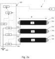
- fig. 2a a three-phase subsea cable system 1 comprising three cable sections 2a, 3a, 4a having a cable length a.
- Each cable section 2a, 3a, 4a has a first conductor 12a, 13a, 14a and a first sheath 22a, 23a, 24a.
- the cable system 1 in fig. 2a may comprise just these three cable sections 2a, 3a, 4a.
- the cable system 1 may comprise two or more cable sections connected to the first cable sections.
- the cable system 1 comprises a control system 90 for monitoring and for controlling the cable system.
- the control system 90 typically monitors voltages, currents and other parameters of the cable system 1 and may be used to operate switches to connect/disconnect the cable system 1 to/from a power system.
- a first end (the left end in fig. 2a ) of the sheaths 22a, 23a, 24a is electrically connected to ground 200 via an earthing conductor 32a, 33a, 34a.
- the monitoring system 100 comprises a current sensor 112 for measuring the current through the earthing conductor 32a, a current sensor 113 for measuring the current through the earthing conductor 33a, and a current sensor 114 for measuring the current through the earthing conductor 34a.
- a current sensor 112 for measuring the current through the earthing conductor 32a
- a current sensor 113 for measuring the current through the earthing conductor 33a
- a current sensor 114 for measuring the current through the earthing conductor 34a.
- there is one sensor for each phase in the three-phase system and they are in the description below commonly referred to as the first sensors 112, 113, 114.
- first sensors 112, 113, 114 are measuring a signal representative of the current Is through the respective sheaths 22a, 23a, 24a. It should be noted that the current Is through the sheath 22a may be different from the current Is through the sheath 23a which again may be different from the current Is through the sheath 24a.
- the first sensors 112, 113, 114 are Neel effect measuring coils. These Need effect measuring coils are relatively small in size, they are sensitive and have an appropriate measurement range. They can therefore be located within a cross-bonding box 20 or similar equipment at the ends of the cable sections or at joints at the cable sections. Hence, this makes it easy to retrofit the monitoring system 100 to existing cable systems 1.
- the monitoring system 100 further comprises a signal processing unit 115 connected to the respective first sensors 112, 113, 114.
- the connections between the first sensors and the signal processing unit 115 are here shown as dashed lines, to separate these connections from the earthing conductors 32a, 33a, 34a.
- the signal processing unit 115 is configured to determine a parameter representative of the state of the respective first sheaths 22a, 23a, 24a.
- the monitoring system 100 comprises a communication unit 116 providing communication between the signal processing unit 115 and the central control system 90.
- the monitoring system 100 may further comprise a temperature sensor 117 connected to the signal processing unit 115 for measuring a parameter representative of the temperature of the sheath.
- the temperature sensor is a distributed temperature sensing unit.
- the distributed temperature sensing unit is here an optoelectronic device comprising an optical fiber and an electronic circuit, for measuring the temperature of the sheath along the majority of the sheath itself, to utilize a more accurate average temperature value instead of a point value.
- an optical fiber was integrated in the cable sections during manufacturing, and is therefore available at the joints of the cable sections.
- a distributed fiber sensor may also be retrofitted. It is commonly known how to evaluate the temperature of different elements of the cable, and in particular of the metallic sheath when measuring temperature in a different, proximal, position.
- sensors may also be used, for example temperature sensorsmeasuring the temperature over the cable surface, at one location, or as a number of sensors measuring the temperature in a quasi-distributed way over several singular positions distributed along the sheaths.
- the monitoring system 100 here comprises a current sensor 112' for measuring a current through the second earthing conductor 32a', a current sensor 113' for measuring a current through the second earthing conductor 33a', and a current sensor 114' for measuring a second current through the second earthing conductor 34a'.
- These sensors 112', 113', 114' are commonly referred to as the second current sensors 112', 113', 114', as they are measuring a signal representative of a second current Is2 through the second end of the sheath 22a, 23a, 24a.
- the first current through the first end of the sheath is here referred to as the first current Is1.
- the second current sensors 112', 113', 114' are connected to the signal processing unit 115.
- the signal processing unit 115 is configured to determine a parameter representative of the state of the first sheath 22a, 23a, 24a based on the signals from the first current sensors 112, 113, 114 and the second current sensors 112', 113', 114'.
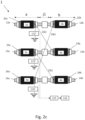
- the third embodiment has many similarities with the second embodiment above, and only differences between the third and second embodiments will be described in detail herein.
- the cable system 1 comprises the first cable section 2a, 2b, 2c as in the second embodiment.
- the cable system 1 comprises a second cable section 2b, 3b, 4b indicated by a cable length b.
- the second cable section 2b, 3b, 4b comprises a second conductor 12b, 13b, 14b connected to the first conductor 12a, 13a, 14a.
- the second cable section 2b, 3b, 4b further comprises a second sheath 22b, 23b, 24b connected to the first sheath 22a, 23a, 24a by means of conducting elements 22j1, 23j1, 24j1.
- the second current sensors 112', 113', 114' are here connected similar to the second embodiment. However, the second current sensors 112', 113', 114' are here measuring a signal representative of the sum of the current through the second end of the sheath 22a, 23a, 24a and the current through the first end of the first sheath.
- the third embodiment is preferably used together with the first embodiment, i.e. the first end of first sheath being grounded.
- the third embodiment may also be used together with the second embodiment where the sheaths at both ends of the cable system 1 are grounded.
- the current sensors 112', 113', 114' in fig. 2c will here be intermediate current sensors.
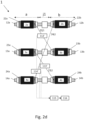
- the fourth embodiment has many similarities with the third embodiment above, and only differences between the fourth and third embodiments will be described in detail herein.
- the second ends of the first sheaths 22a, 23a, 24a are not connected to ground.
- the second current sensors 112', 113', 114' are measuring the current through the respective conducting elements 22j 1, 23j 1, 24j1 used to connect the first end (left side in fig. 2d ) of the second sheath 22b, 23b, 24b to the second end (right side in fig. 2d ) of the first sheath 22a, 23a, 24a.
- the fifth embodiment has many similarities with the second embodiment above and only differences between the fourth and third embodiments will be described in detail herein.
- each phase of the cable system 1 comprises three cable sections.
- the first cable section is indicated as 2a, 3a, 4a
- the second cable section is indicated as 2b, 3b 4b
- the third cable section is indicated as 2c, 3c, 4c.
- the sheaths between the cable sections are cross-bonded to each other at the joints. However, the sheaths are not connected to ground at the joints.
- the fifth embodiment is similar to the second embodiment in that only the ends of the interconnected sheaths are connected to ground as indicated in fig. 8a .
- step S1 the signal processing unit 115 is receiving the signal representative of the current through the first end of the sheaths 22a, 23a, 24a.
- a first parameter representative of the state of the first sheath 22a, 23a, 24a is a current difference ⁇ I between the current Is through the sheath 22a, 23a, 24a and an expected current value Ie.
- the current Is is compared with an expected current value Ie.
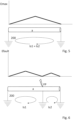
- Each cable system is characterized by its sheath maximum induced voltage Emax such maximum induced voltage is a characteristic of the energy transmission link geometry, depending e.g. on the distance among phases, the soil characteristics, the cable geometry and dimensions.
- a normal situation i.e. no fault is present
- the induced voltage Emax will increase along the length of the first sheath.
- the expected current value Ie is here zero, the measured current Is is zero and hence the current difference ⁇ I is also zero.
- a normal state is determined (indicated in fig. 7 as S4).
- a fault in the sheath is present at a fault position FP, causing the sheath to be grounded at this fault position FP.
- This will change the induced voltage, indicated in fig. 4 as Efault, and also the current through the sheath.
- the after-fault induced voltage Efault is proportional to the ratio of the minor section length to the distance among the design earthing point and the fault location.
- the current Is will flow through the sheath between the first end of the sheath and the fault position FP.
- the current difference ⁇ I is now different from zero.
- a second parameter representative of the state of the first sheath 22a, 23a, 24a is the fault position FP for the fault in the first cable section 2a, 3a, 4a.
- step S3 this fault position FP is calculated.
- the impedance per length unit of sheath can be determined from properties of the cable itself and cable geometry. In addition, the impedance per length unit will be more accurately determined by taking the temperature of the sheath into consideration.
- circuital impedance can be evaluated as the sum of the sheath resistance, linearly dependent to the faulted length between earthing points, the ground resistance (independent from the distance from grounding points), and the distance assumed by the return current from the cable sheath. This third factor is also independent from the distance between earthing points.
- the state of the first sheath is now that a fault is present and the fault position FP is also known (indicated in fig. 7 as S5). This can be communicated as an error notification via the communication unit 116 to the control system 90.
- the expected value Ie for the first current Is1 is here different from zero, and the expected value Ie for the second current Is2 is here different from zero.
- a fault at the fault position FP creating a path to ground.
- the induced voltage Efault is different from Emax, the first current Is 1 changes, and the second current Is2 changes.
- one error may result in one or two error notifications.
- the fault position FP can be calculated based on both the first and second currents Is1 and Is2. By using both the first and second currents Is1 and Is2, a more accurate fault position can be calculated.
- the above method will typically be performed by a computer program executed on the signal processing unit 15. It should be noted that the signal processing unit 15 itself does not need to determine if the SVL element should be replaced or when it should be replaced. This can be a manual operation, or an automatic operation, wherein additional factors than those mentioned above may be taken into consideration (for example economic factors and/or other technical factors).
- the signal processing unit 115 may be located distant from the sensors 112, 113, 113 (and in some embodiments also sensors 112', 113', 114'), and that the unit 115 may be implemented as part of the central control system 90.
- the communication unit 116 is providing communication between the sensors and the signal processing unit, wherein the signal representative of the current through the sheath is transferred by means of the communication unit from the sensors to the signal processing unit.
Landscapes
- Physics & Mathematics (AREA)
- General Physics & Mathematics (AREA)
- Testing Of Short-Circuits, Discontinuities, Leakage, Or Incorrect Line Connections (AREA)
- Locating Faults (AREA)
Claims (12)
- Überwachungssystem (100) zum Überwachen des Zustands eines elektrischen Kabelsystems (1), wobei das elektrische Kabelsystem (1) Folgendes umfasst:- einen ersten Kabelabschnitt (2a, 3a, 4a), umfassend einen ersten Leiter (12a, 13a, 14a) und einen ersten Mantel (22a, 23a, 24a);wobei das Überwachungssystem (100) Folgendes umfasst:- einen ersten Stromsensor (112, 113, 114) zum Messen eines Signals, das repräsentativ für den Strom (Is; Is1) durch den Mantel (22a, 23a, 24a) ist;- eine Signalverarbeitungseinheit (115), die mit dem ersten Stromsensor (112, 113, 114) verbunden ist, zum Verarbeiten des Signals, das repräsentativ für den Strom (Is; Is) durch den Mantel (22a, 23a, 24a) ist;wobei die Signalverarbeitungseinheit (115) zu Folgendem konfiguriert ist:- Bestimmen eines Parameters, der repräsentativ für den Zustand des ersten Mantels (22a, 23a, 24a) des ersten Kabelabschnitts (2a, 3a, 4a) des elektrischen Kabelsystems (1) ist, basierend auf dem Signal von dem Stromsensor (112, 113, 114),das Überwachungssystem (100) ferner umfassend:
eine Kommunikationseinheit (116), die eine Kommunikation zwischen der Signalverarbeitungseinheit (115) und einem zentralen Steuersystem (90) bereitstellt und dadurch gekennzeichnet ist, dass der Parameter, der repräsentativ für den Zustand des ersten Mantels (22a, 23a, 24a) ist, eine Stromdifferenz (ΔI) zwischen dem Strom (Is) durch den Mantel (22a, 23a, 24a) und einem erwarteten Stromwert (le) ist. - Überwachungssystem nach Anspruch 1, wobei der erste Stromsensor (112, 113, 114) eine Neel-Effekt-Messspule umfasst.
- Überwachungssystem nach einem der vorherigen Ansprüche, wobei das Kabelsystem (1) einen Erdungsleiter (32a, 33a, 34a) umfasst, der elektrisch zwischen einem ersten Ende des ersten Mantels (22a, 23a, 24a) und Erde (200) verbunden ist; und wobei der erste Stromsensor (112, 113, 114) den Strom durch den Erdungsleiter (32a, 33a, 34a) misst, wobei der Strom durch den Erdungsleiter (32a, 33a, 34a) das Signal ist, das repräsentativ für den ersten Strom (Is; Is1) durch das erste Ende des Mantels (22a, 23a, 24a) ist.
- Überwachungssystem nach Anspruch 3, wobei:- das Überwachungssystem (100) einen zweiten Stromsensor (112', 113', 114') umfasst;- der zweite Stromsensor (112', 113', 114') ein Signal misst, das repräsentativ für einen zweiten Strom (Is2) durch ein zweites Ende des Mantels (22a, 23a, 24a) ist;- die Signalverarbeitungseinheit (115) mit dem zweiten Stromsensor (112', 113', 114') verbunden ist, zum Verarbeiten des Signals, das repräsentativ für einen zweiten Strom (Is2) durch das zweite Ende des Mantels (22a, 23a, 24a) ist;wobei die Signalverarbeitungseinheit (115) zu Folgendem konfiguriert ist:- Bestimmen eines Parameters, der repräsentativ für den Zustand des ersten Mantels (22a, 23a, 24a) ist, basierend auf dem Signal von dem ersten Stromsensor (112, 113, 114) und dem zweiten Stromsensor (112', 113', 114').
- Überwachungssystem nach Anspruch 4, wobei das Kabelsystem (1) einen zweiten Erdungsleiter (32a', 33a', 34a') umfasst, der elektrisch zwischen dem zweiten Ende des ersten Mantels (22a, 23a, 24a) und Erde (200) verbunden ist; wobei der zweite Stromsensor (112', 113', 114') den Strom durch den zweiten Erdungsleiter (32a', 33a', 34a') misst.
- Überwachungssystem nach Anspruch 4, wobei das elektrische Kabelsystem (1) Folgendes umfasst:- einen zweiten Kabelabschnitt (2b, 3, 4b), umfassend einen Leiter (12b, 13b, 14b) und einen zweiten Mantel (22b, 23b, 24b);- ein leitendes Element (22jl, 23j1, 24jl) zum Verbinden des ersten Mantels (22a, 23a, 24a) mit dem zweiten Mantel (22b, 23b, 24b);wobei der zweite Stromsensor (112', 113', 114') den Strom durch das leitende Element (22j1, 23j1, 24j1) misst.
- Überwachungssystem nach einem der vorherigen Ansprüche, wobei der Parameter, der repräsentativ für den Zustand des ersten Mantels (22a, 23a, 24a) ist, eine Fehlerposition (FP) für den Fehler in dem ersten Kabelabschnitt (2a, 3a, 4a) ist.
- Überwachungssystem nach einem der obigen Ansprüche, wobei das Überwachungssystem (100) ferner Folgendes umfasst:- einen Temperatursensor (117) zum Messen eines Parameters, der repräsentativ für die Temperatur des Mantels ist, wobei der Temperatursensor (117) mit der Signalverarbeitungseinheit (115) verbunden ist.
- Verfahren zum Überwachen des Zustands eines Mantels (22a, 23a, 24a) eines Kabelabschnitts (2a, 3a, 4a) eines elektrischen Kabelsystems (1), wobei das Verfahren die folgenden Schritte umfasst:- Messen eines Signals, das repräsentativ für einen Strom (Is; Is1) durch den Mantel (22a, 23a, 24a) in einem Überwachungssystem (100) ist;- Bestimmen eines Parameters, der repräsentativ für den Zustand des Mantels (22a, 23a, 24a) ist, basierend auf dem Signal von dem Stromsensor (112, 113, 114) in einer Signalverarbeitungseinheit (115) in dem Überwachungssystem (100);- Bereitstellen von Kommunikation zwischen der Signalverarbeitungseinheit (115) und einem zentralen Steuersystem (90);wobei das Verfahren dadurch gekennzeichnet ist, dass es ferner den folgenden Schritt umfasst:- Bestimmen des Parameters, der repräsentativ für den Zustand des ersten Mantels (22a, 23a, 24a) ist, als Stromdifferenz (ΔI) zwischen dem Strom (Is) durch den Mantel (22a, 23a, 24a) und einem erwarteten Stromwert (le).
- Verfahren nach Anspruch 9, wobei das Verfahren ferner den folgenden Schritt umfasst:- Bestimmen des Parameters, der repräsentativ für den Zustand des ersten Mantels (22a, 23a, 24a) ist, als Fehlerposition (FP), die eine Position eines Fehlers in dem Kabelabschnitt (2a, 3a, 4a) angibt.
- Verfahren nach Anspruch 9, wobei der Schritt eines Messens des Signals, das repräsentativ für den Strom (Is) durch den Mantel (22a, 23a, 24a) ist, Folgendes umfasst:- Messen eines Signals, das repräsentativ für einen ersten Strom (Is1) durch ein erstes Ende des Mantels (22a, 23a, 24a) ist;wobei das Verfahren ferner die folgenden Schritte umfasst:- Messen eines Signals, das repräsentativ für einen zweiten Strom (Is2) durch ein zweites Ende des Mantels (22a, 23a, 24a) ist;- Bestimmen des Parameters, der repräsentativ für den Zustand des ersten Mantels (22a, 23a, 24a) ist, basierend auf dem ersten Strom (Is1) durch das erste Ende des ersten Mantels (22a, 23a, 24a) und basierend auf dem zweiten Strom (Is2) durch das zweite Ende des ersten Mantels (22a, 23a, 24a).
- Computerprogrammprodukt, umfassend ein nicht-transitorisches computerlesbares Speichermedium, umfassend Anweisungen, die, wenn sie auf einer Signalverarbeitungseinheit (115) in einem Überwachungssystem (100) nach einem der Ansprüche 1-8 ausgeführt werden, die Signalverarbeitungseinheit (115) veranlassen, die Schritte des Verfahrens nach Anspruch 9-11 durchzuführen.
Priority Applications (2)
| Application Number | Priority Date | Filing Date | Title |
|---|---|---|---|
| ES21305396T ES3007630T3 (en) | 2021-03-29 | 2021-03-29 | Sheath integrity monitoring |
| EP21305396.0A EP4067921B1 (de) | 2021-03-29 | 2021-03-29 | Überwachung der integrität einer hülle |
Applications Claiming Priority (1)
| Application Number | Priority Date | Filing Date | Title |
|---|---|---|---|
| EP21305396.0A EP4067921B1 (de) | 2021-03-29 | 2021-03-29 | Überwachung der integrität einer hülle |
Publications (3)
| Publication Number | Publication Date |
|---|---|
| EP4067921A1 EP4067921A1 (de) | 2022-10-05 |
| EP4067921C0 EP4067921C0 (de) | 2024-10-02 |
| EP4067921B1 true EP4067921B1 (de) | 2024-10-02 |
Family
ID=75588136
Family Applications (1)
| Application Number | Title | Priority Date | Filing Date |
|---|---|---|---|
| EP21305396.0A Active EP4067921B1 (de) | 2021-03-29 | 2021-03-29 | Überwachung der integrität einer hülle |
Country Status (2)
| Country | Link |
|---|---|
| EP (1) | EP4067921B1 (de) |
| ES (1) | ES3007630T3 (de) |
Families Citing this family (2)
| Publication number | Priority date | Publication date | Assignee | Title |
|---|---|---|---|---|
| CN116299050B (zh) * | 2023-05-17 | 2023-08-11 | 广东电网有限责任公司汕尾供电局 | 一种护层故障检测方法、系统、设备及存储介质 |
| CN117031357B (zh) * | 2023-10-08 | 2024-01-19 | 江苏省电力试验研究院有限公司 | 单端接地的单芯电缆金属护套的接地缺陷定位方法及装置 |
Citations (1)
| Publication number | Priority date | Publication date | Assignee | Title |
|---|---|---|---|---|
| KR20200036479A (ko) * | 2018-09-28 | 2020-04-07 | 한국전력공사 | 케이블 접속함 다기능 진단시스템 |
Family Cites Families (5)
| Publication number | Priority date | Publication date | Assignee | Title |
|---|---|---|---|---|
| JPH08304487A (ja) * | 1995-05-08 | 1996-11-22 | Hitachi Cable Ltd | 活線状態のケーブルシースの絶縁診断方法 |
| GB9805019D0 (en) * | 1998-03-11 | 1998-05-06 | Bicc Plc | Method of and apparatus for detecting cable oversheath faults and installations in which they are used |
| US10139433B2 (en) * | 2014-03-24 | 2018-11-27 | Prysmian S.P.A. | Method of measuring current distribution in high and medium voltage cables |
| CN106716760A (zh) * | 2014-07-18 | 2017-05-24 | 普睿司曼股份公司 | 电力线缆链接装置和包括该装置的电力线缆系统 |
| FR3037406B1 (fr) * | 2015-06-15 | 2017-06-02 | Renault Sas | Systeme electrique comportant un circuit de detection d’un defaut d’isolement electrique |
-
2021
- 2021-03-29 EP EP21305396.0A patent/EP4067921B1/de active Active
- 2021-03-29 ES ES21305396T patent/ES3007630T3/es active Active
Patent Citations (1)
| Publication number | Priority date | Publication date | Assignee | Title |
|---|---|---|---|---|
| KR20200036479A (ko) * | 2018-09-28 | 2020-04-07 | 한국전력공사 | 케이블 접속함 다기능 진단시스템 |
Also Published As
| Publication number | Publication date |
|---|---|
| EP4067921C0 (de) | 2024-10-02 |
| EP4067921A1 (de) | 2022-10-05 |
| ES3007630T3 (en) | 2025-03-20 |
Similar Documents
| Publication | Publication Date | Title |
|---|---|---|
| Dong et al. | Online monitoring and diagnosis of HV cable faults by sheath system currents | |
| US20120330582A1 (en) | Method of high impedance groundfault detection for differential protection of overhead transmission lines | |
| US10761117B2 (en) | Voltage sensor | |
| EP3236272B1 (de) | Hochspannungseinleitungsisolierende vorrichtung | |
| CN107735690A (zh) | 三相电气网络的接地故障保护的方法 | |
| EP4067921A1 (de) | Überwachung der integrität einer hülle | |
| Khamlichi et al. | Measuring cable sheath currents to detect defects in cable sheath connections | |
| EP0942292B1 (de) | Gerät und Verfahren zur Erfassung von Fehlern eines Kabelisolierungsmantels und Anlagen die sie benutzen | |
| KR100918516B1 (ko) | 전력구의 맨홀에 설치된 접지전극의 접지저항을 측정하는 방법 | |
| CN109920601B (zh) | 一种适用于局部放电检测定位的电力电缆 | |
| EP4067916A1 (de) | Überwachung der mantelspannungsbegrenzer (svl) - integrität | |
| EP4257987B1 (de) | Verfahren zum lokalisieren eines fehlerpunktes auf einem hochspannungs-drehstromkabel und system zum lokalisieren eines fehlerpunktes | |
| JP2001141770A (ja) | 高圧ケーブルのシールドテープ断線検出方法及びシールドテープ断線検出装置並びにシールドテーブ断線判定装置 | |
| JP6069051B2 (ja) | 電力ケーブル高抵抗絶縁不良箇所標定方法及び装置 | |
| Yang et al. | On-line monitoring and trending analysis of dielectric losses in cross-bonded high voltage cable systems | |
| CN118707223B (zh) | 输电电缆避雷器阻性电流的监测方法及监测系统 | |
| EP2230736B1 (de) | Verkapselungssystem für einphasige verkapselte Schaltanlage | |
| US12470015B2 (en) | Arc flash protection systems and methods | |
| EP4322354B1 (de) | Verfahren und vorrichtung zum differentiellen schutz einer dreiphasigen elektrischen verbindung | |
| JP2850463B2 (ja) | 電力ケーブルの劣化診断法 | |
| EP4283267B1 (de) | Überwachung der integrität von cross-bonding-boxen | |
| KR20240108797A (ko) | 배전시스템 | |
| Sofwan et al. | Leak Current Monitoring System On The Ground Cables Medium Voltage Transformer 150/20 kV | |
| CN121208547A (zh) | 一种高压电缆外护套绝缘在线监测方法、装置及系统 | |
| HK1022352A (en) | Method of and apparatus for detecting cable oversheath faults and installations in which they are used |
Legal Events
| Date | Code | Title | Description |
|---|---|---|---|
| PUAI | Public reference made under article 153(3) epc to a published international application that has entered the european phase |
Free format text: ORIGINAL CODE: 0009012 |
|
| STAA | Information on the status of an ep patent application or granted ep patent |
Free format text: STATUS: THE APPLICATION HAS BEEN PUBLISHED |
|
| AK | Designated contracting states |
Kind code of ref document: A1 Designated state(s): AL AT BE BG CH CY CZ DE DK EE ES FI FR GB GR HR HU IE IS IT LI LT LU LV MC MK MT NL NO PL PT RO RS SE SI SK SM TR |
|
| STAA | Information on the status of an ep patent application or granted ep patent |
Free format text: STATUS: REQUEST FOR EXAMINATION WAS MADE |
|
| 17P | Request for examination filed |
Effective date: 20230405 |
|
| RBV | Designated contracting states (corrected) |
Designated state(s): AL AT BE BG CH CY CZ DE DK EE ES FI FR GB GR HR HU IE IS IT LI LT LU LV MC MK MT NL NO PL PT RO RS SE SI SK SM TR |
|
| STAA | Information on the status of an ep patent application or granted ep patent |
Free format text: STATUS: EXAMINATION IS IN PROGRESS |
|
| 17Q | First examination report despatched |
Effective date: 20231031 |
|
| GRAP | Despatch of communication of intention to grant a patent |
Free format text: ORIGINAL CODE: EPIDOSNIGR1 |
|
| STAA | Information on the status of an ep patent application or granted ep patent |
Free format text: STATUS: GRANT OF PATENT IS INTENDED |
|
| INTG | Intention to grant announced |
Effective date: 20240613 |
|
| GRAS | Grant fee paid |
Free format text: ORIGINAL CODE: EPIDOSNIGR3 |
|
| GRAA | (expected) grant |
Free format text: ORIGINAL CODE: 0009210 |
|
| STAA | Information on the status of an ep patent application or granted ep patent |
Free format text: STATUS: THE PATENT HAS BEEN GRANTED |
|
| AK | Designated contracting states |
Kind code of ref document: B1 Designated state(s): AL AT BE BG CH CY CZ DE DK EE ES FI FR GB GR HR HU IE IS IT LI LT LU LV MC MK MT NL NO PL PT RO RS SE SI SK SM TR |
|
| REG | Reference to a national code |
Ref country code: GB Ref legal event code: FG4D |
|
| REG | Reference to a national code |
Ref country code: CH Ref legal event code: EP |
|
| REG | Reference to a national code |
Ref country code: IE Ref legal event code: FG4D |
|
| REG | Reference to a national code |
Ref country code: DE Ref legal event code: R096 Ref document number: 602021019570 Country of ref document: DE |
|
| U01 | Request for unitary effect filed |
Effective date: 20241022 |
|
| U07 | Unitary effect registered |
Designated state(s): AT BE BG DE DK EE FI FR IT LT LU LV MT NL PT RO SE SI Effective date: 20241105 |
|
| U1N | Appointed representative for the unitary patent procedure changed after the registration of the unitary effect |
Representative=s name: ONSAGERS AS; NO |
|
| REG | Reference to a national code |
Ref country code: ES Ref legal event code: FG2A Ref document number: 3007630 Country of ref document: ES Kind code of ref document: T3 Effective date: 20250320 |
|
| PG25 | Lapsed in a contracting state [announced via postgrant information from national office to epo] |
Ref country code: IS Free format text: LAPSE BECAUSE OF FAILURE TO SUBMIT A TRANSLATION OF THE DESCRIPTION OR TO PAY THE FEE WITHIN THE PRESCRIBED TIME-LIMIT Effective date: 20250202 Ref country code: HR Free format text: LAPSE BECAUSE OF FAILURE TO SUBMIT A TRANSLATION OF THE DESCRIPTION OR TO PAY THE FEE WITHIN THE PRESCRIBED TIME-LIMIT Effective date: 20241002 |
|
| U20 | Renewal fee for the european patent with unitary effect paid |
Year of fee payment: 5 Effective date: 20250310 |
|
| PG25 | Lapsed in a contracting state [announced via postgrant information from national office to epo] |
Ref country code: GR Free format text: LAPSE BECAUSE OF FAILURE TO SUBMIT A TRANSLATION OF THE DESCRIPTION OR TO PAY THE FEE WITHIN THE PRESCRIBED TIME-LIMIT Effective date: 20250103 |
|
| PG25 | Lapsed in a contracting state [announced via postgrant information from national office to epo] |
Ref country code: PL Free format text: LAPSE BECAUSE OF FAILURE TO SUBMIT A TRANSLATION OF THE DESCRIPTION OR TO PAY THE FEE WITHIN THE PRESCRIBED TIME-LIMIT Effective date: 20241002 Ref country code: CZ Free format text: LAPSE BECAUSE OF FAILURE TO SUBMIT A TRANSLATION OF THE DESCRIPTION OR TO PAY THE FEE WITHIN THE PRESCRIBED TIME-LIMIT Effective date: 20241002 |
|
| PG25 | Lapsed in a contracting state [announced via postgrant information from national office to epo] |
Ref country code: RS Free format text: LAPSE BECAUSE OF FAILURE TO SUBMIT A TRANSLATION OF THE DESCRIPTION OR TO PAY THE FEE WITHIN THE PRESCRIBED TIME-LIMIT Effective date: 20250102 |
|
| PG25 | Lapsed in a contracting state [announced via postgrant information from national office to epo] |
Ref country code: SM Free format text: LAPSE BECAUSE OF FAILURE TO SUBMIT A TRANSLATION OF THE DESCRIPTION OR TO PAY THE FEE WITHIN THE PRESCRIBED TIME-LIMIT Effective date: 20241002 |
|
| PGFP | Annual fee paid to national office [announced via postgrant information from national office to epo] |
Ref country code: ES Payment date: 20250409 Year of fee payment: 5 |
|
| PG25 | Lapsed in a contracting state [announced via postgrant information from national office to epo] |
Ref country code: SK Free format text: LAPSE BECAUSE OF FAILURE TO SUBMIT A TRANSLATION OF THE DESCRIPTION OR TO PAY THE FEE WITHIN THE PRESCRIBED TIME-LIMIT Effective date: 20241002 |
|
| PLBE | No opposition filed within time limit |
Free format text: ORIGINAL CODE: 0009261 |
|
| STAA | Information on the status of an ep patent application or granted ep patent |
Free format text: STATUS: NO OPPOSITION FILED WITHIN TIME LIMIT |
|
| 26N | No opposition filed |
Effective date: 20250703 |
|
| PG25 | Lapsed in a contracting state [announced via postgrant information from national office to epo] |
Ref country code: MC Free format text: LAPSE BECAUSE OF FAILURE TO SUBMIT A TRANSLATION OF THE DESCRIPTION OR TO PAY THE FEE WITHIN THE PRESCRIBED TIME-LIMIT Effective date: 20241002 |
|
| REG | Reference to a national code |
Ref country code: CH Ref legal event code: H13 Free format text: ST27 STATUS EVENT CODE: U-0-0-H10-H13 (AS PROVIDED BY THE NATIONAL OFFICE) Effective date: 20251023 |
|
| PG25 | Lapsed in a contracting state [announced via postgrant information from national office to epo] |
Ref country code: CH Free format text: LAPSE BECAUSE OF NON-PAYMENT OF DUE FEES Effective date: 20250331 |
|
| PG25 | Lapsed in a contracting state [announced via postgrant information from national office to epo] |
Ref country code: IE Free format text: LAPSE BECAUSE OF NON-PAYMENT OF DUE FEES Effective date: 20250329 |
|
| U20 | Renewal fee for the european patent with unitary effect paid |
Year of fee payment: 6 Effective date: 20260205 |
|
| PGFP | Annual fee paid to national office [announced via postgrant information from national office to epo] |
Ref country code: GB Payment date: 20260213 Year of fee payment: 6 |
|
| PGFP | Annual fee paid to national office [announced via postgrant information from national office to epo] |
Ref country code: NO Payment date: 20260114 Year of fee payment: 6 |