EP4067933B1 - Vorrichtung und verfahren zur berechnung der fischgrösse - Google Patents
Vorrichtung und verfahren zur berechnung der fischgrösse Download PDFInfo
- Publication number
- EP4067933B1 EP4067933B1 EP21166152.5A EP21166152A EP4067933B1 EP 4067933 B1 EP4067933 B1 EP 4067933B1 EP 21166152 A EP21166152 A EP 21166152A EP 4067933 B1 EP4067933 B1 EP 4067933B1
- Authority
- EP
- European Patent Office
- Prior art keywords
- fish
- tracked
- incidence angle
- distance
- ultrasound
- Prior art date
- Legal status (The legal status is an assumption and is not a legal conclusion. Google has not performed a legal analysis and makes no representation as to the accuracy of the status listed.)
- Active
Links
Images






Classifications
-
- A—HUMAN NECESSITIES
- A61—MEDICAL OR VETERINARY SCIENCE; HYGIENE
- A61B—DIAGNOSIS; SURGERY; IDENTIFICATION
- A61B8/00—Diagnosis using ultrasonic, sonic or infrasonic waves
- A61B8/08—Clinical applications
-
- G—PHYSICS
- G01—MEASURING; TESTING
- G01S—RADIO DIRECTION-FINDING; RADIO NAVIGATION; DETERMINING DISTANCE OR VELOCITY BY USE OF RADIO WAVES; LOCATING OR PRESENCE-DETECTING BY USE OF THE REFLECTION OR RERADIATION OF RADIO WAVES; ANALOGOUS ARRANGEMENTS USING OTHER WAVES
- G01S7/00—Details of systems according to groups G01S13/00, G01S15/00, G01S17/00
- G01S7/52—Details of systems according to groups G01S13/00, G01S15/00, G01S17/00 of systems according to group G01S15/00
- G01S7/539—Details of systems according to groups G01S13/00, G01S15/00, G01S17/00 of systems according to group G01S15/00 using analysis of echo signal for target characterisation; Target signature; Target cross-section
-
- A—HUMAN NECESSITIES
- A61—MEDICAL OR VETERINARY SCIENCE; HYGIENE
- A61B—DIAGNOSIS; SURGERY; IDENTIFICATION
- A61B8/00—Diagnosis using ultrasonic, sonic or infrasonic waves
-
- A—HUMAN NECESSITIES
- A61—MEDICAL OR VETERINARY SCIENCE; HYGIENE
- A61B—DIAGNOSIS; SURGERY; IDENTIFICATION
- A61B8/00—Diagnosis using ultrasonic, sonic or infrasonic waves
- A61B8/52—Devices using data or image processing specially adapted for diagnosis using ultrasonic, sonic or infrasonic waves
- A61B8/5207—Devices using data or image processing specially adapted for diagnosis using ultrasonic, sonic or infrasonic waves involving processing of raw data to produce diagnostic data, e.g. for generating an image
-
- A—HUMAN NECESSITIES
- A61—MEDICAL OR VETERINARY SCIENCE; HYGIENE
- A61B—DIAGNOSIS; SURGERY; IDENTIFICATION
- A61B8/00—Diagnosis using ultrasonic, sonic or infrasonic waves
- A61B8/52—Devices using data or image processing specially adapted for diagnosis using ultrasonic, sonic or infrasonic waves
- A61B8/5215—Devices using data or image processing specially adapted for diagnosis using ultrasonic, sonic or infrasonic waves involving processing of medical diagnostic data
-
- G—PHYSICS
- G01—MEASURING; TESTING
- G01G—WEIGHING
- G01G17/00—Apparatus for or methods of weighing material of special form or property
- G01G17/08—Apparatus for or methods of weighing material of special form or property for weighing livestock
-
- G—PHYSICS
- G01—MEASURING; TESTING
- G01S—RADIO DIRECTION-FINDING; RADIO NAVIGATION; DETERMINING DISTANCE OR VELOCITY BY USE OF RADIO WAVES; LOCATING OR PRESENCE-DETECTING BY USE OF THE REFLECTION OR RERADIATION OF RADIO WAVES; ANALOGOUS ARRANGEMENTS USING OTHER WAVES
- G01S15/00—Systems using the reflection or reradiation of acoustic waves, e.g. sonar systems
- G01S15/02—Systems using the reflection or reradiation of acoustic waves, e.g. sonar systems using reflection of acoustic waves
- G01S15/06—Systems determining the position data of a target
- G01S15/08—Systems for measuring distance only
-
- G—PHYSICS
- G01—MEASURING; TESTING
- G01S—RADIO DIRECTION-FINDING; RADIO NAVIGATION; DETERMINING DISTANCE OR VELOCITY BY USE OF RADIO WAVES; LOCATING OR PRESENCE-DETECTING BY USE OF THE REFLECTION OR RERADIATION OF RADIO WAVES; ANALOGOUS ARRANGEMENTS USING OTHER WAVES
- G01S15/00—Systems using the reflection or reradiation of acoustic waves, e.g. sonar systems
- G01S15/02—Systems using the reflection or reradiation of acoustic waves, e.g. sonar systems using reflection of acoustic waves
- G01S15/50—Systems of measurement, based on relative movement of the target
-
- G—PHYSICS
- G01—MEASURING; TESTING
- G01S—RADIO DIRECTION-FINDING; RADIO NAVIGATION; DETERMINING DISTANCE OR VELOCITY BY USE OF RADIO WAVES; LOCATING OR PRESENCE-DETECTING BY USE OF THE REFLECTION OR RERADIATION OF RADIO WAVES; ANALOGOUS ARRANGEMENTS USING OTHER WAVES
- G01S15/00—Systems using the reflection or reradiation of acoustic waves, e.g. sonar systems
- G01S15/66—Sonar tracking systems
-
- G—PHYSICS
- G01—MEASURING; TESTING
- G01S—RADIO DIRECTION-FINDING; RADIO NAVIGATION; DETERMINING DISTANCE OR VELOCITY BY USE OF RADIO WAVES; LOCATING OR PRESENCE-DETECTING BY USE OF THE REFLECTION OR RERADIATION OF RADIO WAVES; ANALOGOUS ARRANGEMENTS USING OTHER WAVES
- G01S15/00—Systems using the reflection or reradiation of acoustic waves, e.g. sonar systems
- G01S15/88—Sonar systems specially adapted for specific applications
- G01S15/96—Sonar systems specially adapted for specific applications for locating fish
-
- A—HUMAN NECESSITIES
- A61—MEDICAL OR VETERINARY SCIENCE; HYGIENE
- A61B—DIAGNOSIS; SURGERY; IDENTIFICATION
- A61B2503/00—Evaluating a particular growth phase or type of persons or animals
- A61B2503/40—Animals
Definitions
- the present disclosure relates to signal processing in a fish finder in an aquaculture environment, and more particularly to fish size calculation using ultrasonic device.
- ultrasound is conventionally used by placing a transducer in water in the fish cage and by acquiring echoes of the fish using a conventional fish finder as explained in for example, WO2020/090287 .
- a weight of the fish can be calculated by calculating the time difference between two consecutive peaks within the echo signal of the fish. The highest peak indicates an echo received from the swimbladder of the fish whereas the other peaks indicate echoes received from other body parts such as a back of the fish.
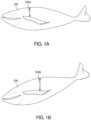
- FIGs. 1A and 1B illustrate such principle.
- FIG. 1A illustrates a fish 100 swimming in a horizontal direction
- FIG. 1B illustrates the fish 100 swimming in a head-down direction. In these two different swimming directions, if ultrasounds are propagating in a vertical direction, the distance between the swimbladder and the back of the fish when the fish swims in the horizontal direction of FIG.
- the distance 102a is the distance between the swimbladder and the back of the fish when the fish swims in the head-down direction of FIG. 1B .
- the distances 102a and 102b may be different.
- the present invention provides a target size calculation device that includes a transducer, a fish tracking module, an ultrasound incidence angle calculation module, a distance calculation module, and a fish weight calculation module.
- the transducer is configured to transmit a transmission wave toward underwater targets and generate an echo signal from a reflection of the transmission wave on the underwater targets.
- the fish tracking module is configured to track in time a fish among the underwater targets from echo signals resulting from different transmission waves.
- the ultrasound incidence angle calculation module is configured to calculate, for each position of the tracked fish in time, an ultrasound incidence angle of the transmission wave on the tracked fish based on the echo signals.
- the distance calculation module is configured to calculate, for each position of the tracked fish in time, a distance between a swimbladder of the tracked fish and a second body part of the tracked fish, different from the swimbladder, from the echo signals of the tracked fish.
- the fish weight calculation module is configured to calculate a weight of the tracked fish based on the ultrasound incidence angle and the calculated distance.
- the target size calculation device includes an ultrasound incidence angle-distance histogram calculation module configured to calculate an ultrasound incidence angle vs. distance histogram from the ultrasound incidence angle and the distance calculated for a plurality of tracked fish.
- the target size calculation device includes a peak extraction module configured to extract a first peak and a second peak from the histogram, and calculate a first peak distance of the first peak on the histogram and a second peak distance of the second peak on the histogram.
- the fish weight calculation module is configured to calculate a mean weight of the plurality of tracked fish from the first peak distance and the second peak distance.
- the present invention provides a target size calculation device that includes a transducer, a fish tracking module, an ultrasound incidence angle calculation module, a distance calculation module, and a fish weight calculation module.
- the transducer is configured to transmit a transmission wave toward underwater targets and generate an echo signal from a reflection of the transmission wave on the underwater targets.
- the fish tracking module is configured to track in time a fish among the underwater targets from echo signals resulting from different transmission waves.
- the ultrasound incidence angle calculation module is configured to calculate, for each position of the tracked fish in time, an ultrasound incidence angle of the transmission wave on the tracked fish based on the echo signals.
- the distance calculation module is configured to calculate, for each position of the tracked fish in time, a distance between a swimbladder of the tracked fish and a second body part of the tracked fish, different from the swimbladder, from the echo signals of the tracked fish.
- the fish weight calculation module is configured to calculate a weight of the tracked fish based on the ultrasound incidence angle and the calculated distance.
- the fish weight calculation module is configured to calculate a weight of the tracked fish when a first ultrasound incidence angle of the transmission wave on the tracked fish at a first timing and a second ultrasound incidence angle of the transmission wave on the tracked fish at a second timing different from the first timing are such that a given threshold angle is in-between the first and second ultrasound incidence angles.
- the fish weight calculation module calculates the weight based on the distance of the tracked fish in the first ultrasound incidence angle and the distance of the tracked fish in the second ultrasound incidence angle.
- the ultrasound incidence angle calculation module calculates the ultrasound incidence angle by calculating an angle made between a second line that connects a position of the tracked fish and the transducer and a third line that is vertical line from the transducer toward bottom of the water.
- a target size calculation method that includes transmitting a transmission wave toward underwater targets and generating an echo signal from a reflection of the transmission wave on the underwater targets using a transducer, tracking in time a fish among the underwater targets from echo signals resulting from different transmission waves, calculating for each position of the tracked fish in time, an ultrasound incidence angle of the transmission wave on the tracked fish based on the echo signals, calculating for each position of the tracked fish in time, a distance between a swimbladder of the tracked fish and a second body part of the tracked fish, different from the swimbladder, from the echo signals of the tracked fish, calculating a weight of the tracked fish based on the ultrasound incidence angle and the calculated distance; and calculating an ultrasound incidence angle vs. distance histogram from the ultrasound incidence angle and the distance calculated for a plurality of tracked fish.
- a non-transitory computer readable medium having stored thereon computer-executable instructions which, when executed by a device of the first aspect of the present invention, cause the device to execute the method of the third aspect of the present invention.
- a non-transitory computer readable medium having stored thereon computer-executable instructions which, when executed by the device of the second aspect of the present invention, cause the device to execute the method of the fifth aspect of the present invention.
- FIG. 2 is a block diagram showing an overall configuration of a target size calculation device 200 , in accordance with a first embodiment of the present invention.
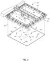
- FIG. 3 is a perspective view showing how the target size calculation device 200 is used in a cage 300 .
- the cage 300 is configured as a net-shaped cage, and includes a frame 301 , a float 302 , a net 303 , and a pier 304 .
- the frame 301 is formed so as to have a loop shape in a plan view.
- a plurality of floats 302 are attached to the frame 301 , whereby the frame 301 can be floated on the surface of the water.
- the frame 301 is connected to a weight on the bottom of the water by a mooring rope (not shown).
- the upper end of the net 303 is fixed to the frame 301 .
- the net 303 is suspended so as to partition the water to form a closed space, and fish of known species are bred inside this space.
- the pier 304 for performing various operations related to aquaculture is fixed on the frame 301 .
- a float 305 is floated in a substantially central portion inside the frame 301 , and the float 305 is connected to the pier 304 by a rope.
- the target size calculation device 200 of the present embodiment is arranged on the float 305 .
- the target size calculation device 200 includes a transducer 22 , a transceiver unit 23 , and a signal processing unit 24 .
- the transducer 22 can mutually convert an electric signal and ultrasonic vibration, and can detect underwater by using a transmitted wave which is an ultrasonic wave.
- the transducer 22 is attached to the lower part of the float 305 .
- the transducer 22 is arranged to transmit downward and transmits ultrasonic waves from the upper side of the water toward the fish in the cage 300 .
- the transducer 22 includes one transmitter and a receiver having a plurality of elements divided into four receiving channels.
- the transducer 22 can acquire a position of an underwater target (such as fish) based on a difference in timing at which the four receiving channels receive a reflected wave reflected on the underwater target (that is, a phase difference of the received reflected wave).
- a position of an underwater target such as fish
- a difference in timing at which the four receiving channels receive a reflected wave reflected on the underwater target that is, a phase difference of the received reflected wave.
- the transceiver unit 23 is connected to the transducer 22 via an electric cable.
- the transceiver unit 23 can output an electric signal to the transducer 22 via the electric cable so that the transducer 22 transmits a transmitted wave. Further, the transceiver unit 23 can acquire via the electric cable an electric signal acquired by the transducer 22 based on the reflected wave. Then, the transceiver unit 23 can convert the electric signal acquired from the transducer 22 into a reception signal which is a digital signal.
- the signal processing unit 24 includes a fish tracking module 25 , an ultrasound incidence angle calculation module 26 , a distance calculation module 27 , an ultrasound incidence angle-distance histogram calculation module 28 , a peak extraction module 29 , and a fish weight calculation module 30 .
- the signal processing unit 24 may be configured as a known computer, and may be communicatively coupled to the transceiver unit 23 through a communication cable to acquire a received signal from the transducer 22 .
- the signal processing unit 24 may include a CPU, a ROM, a RAM, and the like.
- a program for realizing the target size calculation method of the present invention may be stored in the ROM or the like.
- the transducer 22 is configured to mutually convert an electric signal and ultrasonic vibration.
- the transducer 22 converts a high power transmission signal provided by the transceiver unit 23 into an ultrasonic wave and transmits the ultrasonic wave underwater.
- the transducer 22 receives reflection wave reflected from underwater targets, converts the reflection wave into an electric signal and outputs the electrical signal back to the transceiver unit 23 .
- the transceiver unit 23 may be configured to amplify and filter the electric signal, A/D convert the electric signal (analog signal) into a reception signal which is a digital signal and store in a memory (not shown) of corresponding signal processing unit.
- the transducer 22 is configured to transmit a transmission wave toward underwater targets and generate an echo signal from a reflection of the transmission wave on the underwater targets.
- underwater targets include, but are not limited to fish, etc.
- the signal processing unit is configured to receive, store and process the echo signals to measure the length, breadth, height and/or weight of fish in water.
- the calculation of fish weight is not limited to the fish raised in the fish cage 300 , for example, the target size calculation device 200 may be attached to a fishing boat and used as a device for estimating the fish weight for a school of fish swimming in the sea, when a fish species of the fish school can be estimated by the fisherman or otherwise measured by a conventional fish finder that can identify fish species.
- FIG. 4 illustrates an example of an envelope 400 of first, second and third echo signals 401 , 402 and 403 generated based on first, second and third transmission waves T1, T2 and T3 by the transducer 22 respectively.
- the first, second and third transmission waves T1, T2 and T3 are transmitted subsequently one after another, and corresponding echo signals 401 , 402 and 403 are stored in a memory (not shown).
- the horizontal axis is time and the vertical axis is Target Strength (TS) which indicates the strength of the received echo signal.
- the target strength is a parameter indicating the degree to which a part of the ultrasonic wave that is scattered by hitting the fish returns in the incident direction, and can be considered to be substantially the same as the echo intensity.
- the fish tracking module 25 tracks in time a fish among the underwater targets from the first, second and third echo signals 401 , 402 and 403 resulting from different transmission waves.
- the fish tracking module 25 is configured to perform a swimbladder peak extraction in the echo signals 401 , 402 and 403 .
- the fish tracking module 25 determines whether or not the target strength value is equal to or higher than a predetermined detection threshold value.
- a peak of an echo signal that is above the given threshold is considered as an echo coming from the swimbladder of a fish, and is hereinafter also referred to as a swimbladder peak.
- the target strength (TS) shows the maximum peak
- this peak can be considered to be derived from the reflected wave reflected by the swimbladder.
- a peak of an echo signal that is below the given threshold corresponds to an echo from other body parts of a fish such as back of fish.
- the threshold is -40dB, such that the first echo signal 401 includes a swimbladder peak P1, the second echo signal 402 includes a swimbladder peak P2, and the third echo signal 403 includes two swimbladder peaks P3 and P4.
- the fish tracking module 25 determines if there is a corresponding swimbladder peak for a previous transmission wave that occurred at about the same timing. If there is such a peak, the two swimbladder peak echoes are considered as actually coming from the same fish. In an example, peaks P1, P2 and P3 occur almost at the same timing, and therefore, can be considered coming from the same fish.
- the fish tracking module 25 performs fish tracking by comparing peak positions on echo signals from two consecutive transmissions.
- the fish tracking module 25 may employ sophisticated tracking algorithms for fish tracking, involving, for example, prediction by the use of Kalman filter.
- FIG. 5A illustrates a tracked fish 500 tracked at two positions using two consecutive transmissions T n-1 and T n by the transducer 22.
- the ultrasound incidence angle calculation module 26 calculates an ultrasound incidence angle of the transmission wave on the tracked fish 500 based on the echo signals.
- the ultrasound incidence angle calculation module 26 calculates an angle at which the transmission wave penetrates into the tracked fish 500 .
- the transducer 22 may include a plurality of transducer elements (which may also be referred to as channels) at reception.
- the ultrasound incidence angle calculation module 26 may calculate a direction of arrival (DOA) of the echoes from the fish 500 using the conventional interferometry principle, i.e., by calculating the phase difference between the echo signals received by the plurality of transducer elements of the transducer 22 .
- DOA direction of arrival
- the transducer 22 may include multiple receiving channels and is capable of obtaining the arrival direction of the reflected wave by interferometry principle (also conventionally known as split beam method). Each receiving channel has a different directivity, and receives the reflected wave reflected from the target in the water. Then, the transducer 22 converts the data related to the received reflected wave into an electric signal. According to the split beam method, an angle between the arrival direction of the reflected wave and the direction of the central axis of the transmitted wave is calculated based on the difference of phase of the electrical signals received by the receiving channels.
- the ultrasound incidence angle calculation module 26 calculates a 3D position of the tracked fish 500 at each transmission. Particularly, for each position, the ultrasound incidence angle calculation module 26 calculates a distance between the fish 500 and the transducer 22 based on time difference between transmission and reception of the echoes of the fish 500 . Then, the ultrasound incidence angle calculation module 26 calculates the 3D position of the fish 500 relative to the transducer 22 based on corresponding DOA of the fish echo and the distance between the fish 500 and the transducer 22 .
- the position of the fish 500 relative to the transducer 22 constitutes a fish-transducer vector 503 , which may vary from one transmission to another.
- the ultrasound incidence angle is a complementary angle of an angle between the swimming direction vector 504 and the fish-transducer vector 503 .
- the ultrasound incidence angle is zero for a fish that is vertically below the transducer 22 , and swims horizontally. It would be apparent to one of ordinary skill in the art, that there is no limitation to the complementary angle explained above for the definition of the ultrasound incidence angle and that, for example, the angle between the swimming direction vector 504 and the fish-transducer vector 503 , as shown in FIG. 5B , could also be used as a definition of the ultrasound incidence angle.
- the ultrasound incidence angle calculation module 26 calculates the ultrasound incidence angle by calculating an angle made between the second line (i.e., the fish-transducer vector 503 ) that connects the position of the tracked fish 500 and the transducer 22 and a third line ( i.e., a vertical direction vector 505 ) that is vertical line from the transducer 22 toward bottom of the water, as shown in FIG. 5C .
- the ultrasound incidence angle may be defined as an angle between the fish-transducer vector 503 and the vertical direction vector 505 .
- the transducer 22 is transmitting vertically downward from above the fish 500 .
- the transducer 22 may also be arranged to transmit vertically upward from below the fish 500 .
- the transducer 22 includes a plurality of receiving channels and the ultrasound incidence angle is calculated based on a calculation of a position of the fish within a beam of the transducer 22 using the conventional split beam method, the scope of the present disclosure is not limited to it.
- the transducer 22 includes a single receiving channel and the ultrasound incidence angle may be calculated using a suitable method. The calculation of the ultrasound incidence angle when the transducer 22 includes the single receiving channel has been explained later.
- FIG. 6 illustrates calculation of a swimbladder-back distance for the tracked fish 500 for a given transmission.
- the swimbladder-back distance is the distance between the swimbladder and back of the fish 500 , and is calculated based on time difference between the swimbladder peak P5 and peak P6 of the back of the fish 500 .
- the distance calculation module 27 of FIG. 2 calculates for each position of the tracked fish, a time difference between the peak P5 in the echo signal corresponding to the swimbladder and the peak P6 corresponding to another body part of the tracked fish. The distance calculation module 27 then converts the time difference into the swimbladder-back distance. It would be apparent to one of ordinary skill in the art, that another body part is not limited to back, and may include fish belly as another outer surface of the fish, or backbone of the fish as an inner part of the fish, etc.
- the following processing may be performed.
- the echo with a maximum echo intensity i.e., a target strength (TS)
- TS target strength
- a peak in the echo signal appearing immediately before that of the swimbladder peak is considered as an echo from the back of the fish 500 .
- a processing circuit (not shown) of the distance calculation module 27 may check the following condition.
- the processing checks within a given time interval of a given duration, extending before the peak corresponding to the back of the fish and starting from the peak corresponding to the back of the fish, whether another peak of at least a given echo intensity exists. If no such other peak exists within that given time interval, the peak appearing immediately before the swimbladder peak is considered as corresponding to the back of the fish with a high reliability.
- the swimbladder-back of fish distance is calculated.
- the time difference between the swimbladder peak and any other peak within the echo signal of the same fish may be used instead.
- the entire range of values of the swimbladder-back distance data and the entire range of values of the ultrasound incidence angle data are divided into a series of intervals and then the number of values (occurrence) that fall into each interval is counted.
- the histogram 700 represents this count number.
- the dark areas of the histogram 700 show combinations of (ultrasound incidence angle, swimbladder-back distance) that most often occur.
- two dark areas can be seen, which illustrates ultrasound incidence angles in which swimbladder-back distance has been most often measured.
- the transducer 22 is installed so as to send the transmitted wave downward from near the water surface. Therefore, a negative value on the horizontal axis means the back side of the fish from the position of the swimbladder (reference position), and a positive value means the ventral side of the fish from the position of the swimbladder.
- FIG. 7B illustrates a histogram (number of occurrence) of the swimbladder-back distance (i.e., horizontal axis in FIG. 7B ) for ultrasound incidence angles between [0, 10deg].
- the horizontal axis of the 1-D histogram 702 is the same as the horizontal axis of the 2-D histogram 700 .
- the vertical axis of the 1-D histogram 702 represents the number of occurrences.
- the peak extraction module 29 may apply a moving average on the 1-D histogram 702 .
- the above described method to extract the first and second peaks from the histogram 700 and calculate the first peak distance H 1 and the second peak distance H 2 performs a conversion of the 2-D histogram 700 into the 1-D histogram 702 . It would be apparent to one of ordinary skill in the art, that there is no limitation to this method as there are several other conventional methods to extract a peak and calculate a distance between that peak and a reference position.
- the [0, 10deg] range and [-20deg, 0] range used for the peak extraction are also not a limitation and may change depending on fish species in the cage 300 , maturity of the fish, etc.
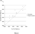
- FIG. 8 illustrates a graph 800 that shows result of five experiments performed with fish type yellowtail in which mean fish weight has been calculated using the conventional fish weight calculation method (as described in WO2020/090287 ) and the target size calculation device 200 .
- FIG. 9 is a block diagram showing an overall configuration of a target size calculation device 900 , in accordance with a second embodiment of the present invention.
- the target size calculation device 900 of the second embodiment differs from the target size calculation device 200 of the first embodiment in the configuration of a fish weight calculation module 901 . Also, the target size calculation device 900 does not include the ultrasound incidence angle-distance histogram calculation module and the peak extraction module of the first embodiment.
- the fish weight calculation module 901 calculates fish weight for each tracked fish. Once a fish is tracked on a plurality of transmissions, the ultrasound incidence angle of the transmission wave on the tracked fish is calculated on each transmission by the ultrasound incidence angle calculation module 26 .
- FIG. 10 illustrates first and second ultrasound incidence angles 1000 and 1001 of a transmission wave on a tracked fish 1002 tracked on first and second transmissions T n-1 and T n by the transducer 22 respectively.
- the first and second ultrasound incidence angles 1000 and 1001 are illustrated as defined by equation (2) and FIG. 5B , but there is no limitation and could also be illustrated as defined by equation (1) and FIG. 5A or as defined by equation (3) and FIG. 5C .
- the fish weight calculation module 901 compares each of the first and second ultrasound incidence angles with a given threshold angle, and calculates a weight of the tracked fish 1002 when the first ultrasound incidence angle and second ultrasound incidence angle are such that the given threshold angle is in-between the first and second ultrasound incidence angles.
- the fish weight calculation module 901 extracts swimbladder-back distances in the first and second ultrasound incidence angles from the distance calculation module 27 .
- the fish weight calculation module 901 extracts swimbladder-back distance in one of the first and second ultrasound incidence angles from the distance calculation module 27.
- the fish weight calculation module 901 may extract swimbladder-back distances in both of the first and second ultrasound incidence angles and calculate an average of both swimbladder-back distances. The fish weight calculation module 901 then calculates the individual fish weight W i of the tracked fish based on the extracted swimbladder-back distance or the averaged swimbladder-back distance.
- the fish weight calculation module 901 is shown to calculate a weight of the tracked fish based on tracking of fish on two transmissions, it would be apparent to one of ordinary skill in the art, that the fish weight may be calculated based on tracking of fish on more than two transmissions.
- the swimbladder-back distances in the other two ultrasound incidence angles may be averaged before using them in the equation (6).
- the fish weight calculation module 901 calculates the fish weight for each tracked fish, and determines a distribution of fish weight within a fish cage upon calculating fish weight of a plurality of tracked fish.
- the fish weight calculation module 901 provides more information, i.e., fish weight distribution about weight of fish within the cage than the fish weight calculation module 30 of the first embodiment that calculates a mean weight of fish within the cage 300 .
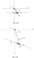
- FIG. 11A illustrates a top view showing the calculation of the ultrasound incidence angle when the transducer 22 includes a single receiving channel, in accordance with an embodiment of the present disclosure.
- FIG. 11B illustrates a side view showing the calculation of the ultrasound incidence angle when the transducer 22 includes a single receiving channel, in accordance with an embodiment of the present disclosure.
- a fish 1100 swims linearly below a single beam transducer 22 (i.e., the transducer 22 that includes a single receiving channel) placed at a fixed position in the fish cage 300 and oriented vertically down.
- a 3D cartesian coordinate system is shown in the FIGs. 11A and 11B , such that the transducer 22 is placed at a center of the 3D cartesian coordinate system.
- the fish 1100 is at a distance r from the transducer 22 and swims at a speed v .
- the fish 1100 crosses the YZ plane.
- the ultrasound incidence angle is an angle between a fish-transducer vector 1101 ( i.e., a first line that connects the fish 1100 and the transducer 22 ) and a perpendicular vector 1102 (i.e., a second line that is perpendicular to a direction in which the fish 1100 is swimming).
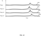
- FIG. 12 illustrates various echo signals, i.e., echo signals 1201 , 1202 , 1203 , and 1204 , generated at different time instances i.e., during pings n , n+1 , n+2 , and n+3 , respectively, when the fish 1100 swims below the single receiving channel transducer 22 .
- a corresponding distance from the fish 1100 to the transducer 22 may be calculated by measuring a time taken by the ultrasonic wave to reflect from the swimbladder of the fish 1100 , by multiplying that time with the speed of sound in water, and by dividing the multiplication result by two.
- the distances r for each ping may be illustrated as below: Table I Ping Distance to fish Ping n r n Ping n+1 r n+1 Ping n+2 r n+2 Ping n+3 T n+3
- the ultrasound incidence angle calculation module 26 calculates the ultrasound incidence angle using equation (9) at each ping by substituting the value of the speed v of the fish 1100 , and the time t p .
- the transducer 22 when the transducer 22 generates the first and second echo signals 1201 and 1202 based on the first and second ultrasonic waves ( i.e., the first and second pings n and n+1 ), the first and second distances r n and r n+1 are calculated as described above, respectively.
- the second ultrasonic wave is transmitted after the first ultrasonic wave.
- the ultrasound incidence angle calculation module 26 calculates a second incidence angle ⁇ n+1 based on the first distance r n between the aquatic animal ( i.e., the fish 1100 ) and the transducer 22 in the first echo signal 1201 and the second distance r n+1 between the aquatic animal and the transducer 22 in the second echo signal 1202 .
- the ultrasound incidence angle calculation module 26 calculates the second incidence angle ⁇ n+1 , based on an assumption that the first and second distances r n and r n+1 change with time based on a hyperbolic curve, using the equation (10).
- FIG. 13 is a flow chart illustrating a method 1300 for target size calculation, in accordance with an embodiment of the present disclosure. Various steps of the method have been explained with reference to FIGs. 2 and 9 .
- the transducer 22 transmits a transmission wave toward underwater targets and generate an echo signal from a reflection of the transmission wave on the underwater targets.
- the fish tracking module 25 tracks in time a fish among the underwater targets from echo signals resulting from different transmission waves.
- the ultrasound incidence angle calculation module 26 calculates, for each position of the tracked fish in time, an ultrasound incidence angle of the transmission wave on the tracked fish based on the echo signals.
- the distance calculation module 27 calculates, for each position of the tracked fish in time, a distance between a swimbladder of the tracked fish and a second body part of the tracked fish, different from the swimbladder, from the echo signals of the tracked fish.
- the fish weight calculation module 30 and 901 calculates a weight of the tracked fish based on the ultrasound incidence angle and the calculated distance.
- All processes described herein may be embodied in, and fully automated via, software code modules executed by a computing system that includes one or more computers or processors.
- the software code modules may be stored in any type of non-transitory computer-readable medium or other computer storage device. Some or all methods may be embodied in specialized computer hardware.
- the various exemplary logical blocks and modules described in connection with the embodiments disclosed herein can be implemented or executed by a machine such as a processor.
- the processor may be a microprocessor, but alternatively, the processor may be a controller, a microcontroller, or a state machine, or a combination thereof.
- the processor can include an electrical circuit configured to process computer executable instructions.
- the processor includes an application specific integrated circuit (ASIC), a field programmable gate array (FPGA), or other programmable device that performs logical operations without processing computer executable instructions.
- ASIC application specific integrated circuit
- FPGA field programmable gate array
- the processor can also be implemented as a combination of computing devices, e.g., a combination of a digital signal processor (DSP) and a microprocessor, a plurality of microprocessors, one or more microprocessors in conjunction with a DSP core, or any other such configuration.
- DSP digital signal processor
- the processor may also include primarily analog components.
- some or all of the signal processing algorithms described herein may be implemented by analog circuitry or mixed analog and digital circuitry.
- a computing environment may include any type of computer system, including, but not limited to, a computer system that is based on a microprocessor, mainframe computer, a digital signal processor, a portable computing device, a device controller, or a computing engine within the device.
- conditional languages such as “can”, “could”, “will”, “might”, or “may” are understood within the context as used in general to convey that certain embodiments include, while other embodiments do not include, certain features, elements and/or steps. Thus, such conditional languages are not generally intended to imply that features, elements and/or steps are in any way required for one or more embodiments or that one or more embodiments necessarily include logic for deciding, with or without user input or prompting, whether these features, elements and/or steps are included or are to be performed in any particular embodiment.
- Disjunctive languages such as the phrase "at least one of X, Y, or Z", unless specifically stated otherwise, is understood with the context as used in general to present that an item, term, etc., may be either X, Y, or Z, or any combination thereof (e.g., X, Y, and/or Z). Thus, such a disjunctive language is not generally intended to, and should not, imply that certain embodiments require at least one of X, at least one of Y, or at least one of Z to each be present.
- a device configured to are intended to include one or more recited devices.
- Such one or more recited devices can also be collectively configured to carry out the stated recitations.
- a processor configured to carry out recitations A, B, and C can include a first processor configured to carry out recitation A working in conjunction with a second processor configured to carry out recitations B and C.
- horizontal is defined as a plane parallel to the plane or surface of the floor of the area in which the system being described is used or the method being described is performed, regardless of its orientation.
- floor can be interchanged with the term “ground” or “water surface”.
- vertical refers to a direction perpendicular to the horizontal as just defined. Terms such as “above”, “below”, “bottom”, “top”, “side”, “higher”, “lower”, “upper”, “over”, and “under”, are defined with respect to the horizontal plane.
- connection As used herein, the terms “attached”, “connected”, “mated” and other such relational terms should be construed, unless otherwise noted, to include removable, moveable, fixed, adjustable, and/or releasable connections or attachments.
- the connections/attachments can include direct connections and/or connections having intermediate structure between the two components discussed.
- Numbers preceded by a term such as “approximately”, “about”, and “substantially” as used herein include the recited numbers, and also represent an amount close to the stated amount that still performs a desired function or achieves a desired result.
- the terms “approximately”, “about”, and “substantially” may refer to an amount that is within less than 10% of the stated amount.
- Features of embodiments disclosed herein preceded by a term such as “approximately”, “about”, and “substantially” as used herein represent the feature with some variability that still performs a desired function or achieves a desired result for that feature.
Landscapes
- Engineering & Computer Science (AREA)
- Physics & Mathematics (AREA)
- Health & Medical Sciences (AREA)
- Life Sciences & Earth Sciences (AREA)
- Radar, Positioning & Navigation (AREA)
- Remote Sensing (AREA)
- General Physics & Mathematics (AREA)
- Computer Networks & Wireless Communication (AREA)
- Pathology (AREA)
- Surgery (AREA)
- Biophysics (AREA)
- Nuclear Medicine, Radiotherapy & Molecular Imaging (AREA)
- Veterinary Medicine (AREA)
- Radiology & Medical Imaging (AREA)
- Biomedical Technology (AREA)
- Heart & Thoracic Surgery (AREA)
- Medical Informatics (AREA)
- Molecular Biology (AREA)
- Public Health (AREA)
- Animal Behavior & Ethology (AREA)
- General Health & Medical Sciences (AREA)
- Acoustics & Sound (AREA)
- Computer Vision & Pattern Recognition (AREA)
- Measurement Of Velocity Or Position Using Acoustic Or Ultrasonic Waves (AREA)
Claims (12)
- Zielgrößenberechnungsvorrichtung, die Folgendes umfasst:einen Wandler (22), konfiguriert zum Übertragen einer Übertragungswelle zu Unterwasserzielen und zum Erzeugen eines Echosignals aus einer Reflexion der Übertragungswelle an den Unterwasserzielen;ein Fischverfolgungsmodul (25), konfiguriert zum zeitlichen Verfolgen eines Fischs unter den Unterwasserzielen anhand von Echosignalen, die von verschiedenen Übertragungswellen stammen;ein Ultraschalleinfallswinkel-Berechnungsmodul (26), konfiguriert zum Berechnen, für jede Position des zeitlich verfolgten Fischs, eines Ultraschalleinfallswinkels der Übertragungswelle auf den verfolgten Fisch auf der Basis der Echosignale;ein Distanzberechnungsmodul (27), konfiguriert zum Berechnen, für jede Position des zeitlich verfolgten Fischs, einer Distanz zwischen einer Schwimmblase des verfolgten Fischs und einem zweiten Körperteil des verfolgten Fischs, der sich von der Schwimmblase unterscheidet, aus den Echosignalen des verfolgten Fischs;ein Fischgewichtberechnungsmodul (30, 901), konfiguriert zum Berechnen eines Gewichts des verfolgten Fischs auf der Basis des Ultraschalleinfallswinkels und der berechneten Distanz; undein Ultraschalleinfallswinkel-Distanz-Histogramm-Berechnungsmodul (28), konfiguriert zum Berechnen eines Ultraschalleinfallswinkel-Distanz-Histogramms aus dem Ultraschalleinfallswinkel und der für mehrere verfolgte Fische berechneten Distanz.
- Zielgrößenberechnungsvorrichtung nach Anspruch 1, die ferner Folgendes umfasst:
ein Peakextraktionsmodul (29), konfiguriert zum Extrahieren eines ersten Peaks und eines zweiten Peaks aus dem Histogramm und zum Berechnen einer ersten Peakdistanz des ersten Peaks auf dem Histogramm und einer zweiten Peakdistanz des zweiten Peaks auf dem Histogramm. - Zielgrößenberechnungsvorrichtung nach Anspruch 2, wobei:
das Fischgewichtberechnungsmodul (30) zum Berechnen eines Durchschnittsgewichts der mehreren verfolgten Fische aus der ersten Peakdistanz und der zweiten Peakdistanz konfiguriert ist. - Zielgrößenberechnungsvorrichtung, die Folgendes umfasst:einen Wandler (22), konfiguriert zum Übertragen einer Übertragungswelle zu Unterwasserzielen und zum Erzeugen eines Echosignals aus einer Reflexion der Übertragungswelle an den Unterwasserzielen;ein Fischverfolgungsmodul (25), konfiguriert zum zeitlichen Verfolgen eines Fischs unter den Unterwasserzielen anhand von Echosignalen, die von verschiedenen Übertragungswellen stammen;ein Ultraschalleinfallswinkel-Berechnungsmodul (26), konfiguriert zum Berechnen, für jede Position des zeitlich verfolgten Fischs, eines Ultraschalleinfallswinkels der Übertragungswelle auf den verfolgten Fisch auf der Basis der Echosignale;ein Distanzberechnungsmodul (27), konfiguriert zum Berechnen, für jede Position des zeitlich verfolgten Fischs, einer Distanz zwischen einer Schwimmblase des verfolgten Fischs und einem zweiten Körperteil des verfolgten Fischs, der sich von der Schwimmblase unterscheidet, aus den Echosignalen des verfolgten Fischs;ein Fischgewichtberechnungsmodul (30, 901), konfiguriert zum Berechnen eines Gewichts des verfolgten Fischs auf der Basis des Ultraschalleinfallswinkels und der berechneten Distanz;wobei das Fischgewichtberechnungsmodul (901) zum Berechnen eines Gewichts des verfolgten Fischs konfiguriert ist, wenn ein erster Ultraschalleinfallswinkel der Übertragungswelle auf den verfolgten Fisch zu einem ersten Zeitpunkt und ein zweiter Ultraschalleinfallswinkel der Übertragungswelle auf den verfolgten Fisch zu einem zweiten Zeitpunkt, der sich vom ersten Zeitpunkt unterscheidet, so sind, dass ein gegebener Schwellenwinkel zwischen dem ersten und dem zweiten Ultraschalleinfallswinkel liegt; und wobei das Fischgewichtberechnungsmodul (901) das Gewicht auf der Basis der Distanz des verfolgten Fischs im ersten Ultraschalleinfallswinkel und der Distanz des verfolgten Fischs im zweiten Ultraschalleinfallswinkel berechnet.
- Zielgrößenberechnungsvorrichtung nach einem der Ansprüche 1 bis 4, wobei:
das Ultraschalleinfallswinkel-Berechnungsmodul (26) den Ultraschalleinfallswinkel durch Berechnen eines Winkels berechnet, der zwischen einer zwei verschiedene Positionen des zeitlich verfolgten Fischs verbindenden ersten Linie und einer eine der zwei verschiedenen Positionen und eine Position des Wandlers verbindenden zweiten Linie gebildet wird. - Zielgrößenberechnungsvorrichtung nach einem der Ansprüche 1 bis 4, wobei:
das Ultraschalleinfallswinkel-Berechnungsmodul (26) den Ultraschalleinfallswinkel durch Berechnen eines Winkels berechnet, der zwischen einer eine Position des verfolgten Fischs und den Wandler verbindenden zweiten Linie und einer dritten Linie gebildet wird, die eine vertikale Linie vom Wandler (22) zum Grund des Wassers ist. - Zielgrößenberechnungsvorrichtung nach einem der Ansprüche 1 bis 4, wobei:
das Ultraschalleinfallswinkel-Berechnungsmodul (26) den Ultraschalleinfallswinkel auf der Basis einer ersten Distanz zwischen dem Wandler und einer ersten Position des verfolgten Fischs zu einem ersten Zeitpunkt und einer zweiten Distanz zwischen dem Wandler und einer zweiten Position des verfolgten Fischs zu einem zweiten Zeitpunkt, der sich vom ersten Zeitpunkt unterscheidet, berechnet; wobei:
das Ultraschalleinfallswinkel-Berechnungsmodul (26) den Ultraschalleinfallswinkel auf der Basis einer Annahme berechnet, dass sich die erste und zweite Distanz zeitlich auf der Basis einer Hyperbelkurve ändern. - Zielgrößenberechnungsvorrichtung nach einem der vorherigen Ansprüche, wobei:
der zweite Körperteil eine Außenfläche des verfolgten Fischs ist. - Zielgrößenberechnungsverfahren, das Folgendes beinhaltet:Übertragen einer Übertragungswelle zu Unterwasserzielen und Erzeugen eines Echosignals aus einer Reflexion der Übertragungswelle an den Unterwasserzielen mittels eines Wandlers;zeitliches Verfolgen eines Fischs unter den Unterwasserzielen anhand von Echosignalen, die von verschiedenen Übertragungswellen stammen;Berechnen, für jede Position des zeitlich verfolgten Fischs, eines Ultraschalleinfallswinkels der Übertragungswelle auf den verfolgten Fisch auf der Basis der Echosignale;Berechnen, für jede Position des zeitlich verfolgten Fischs, einer Distanz zwischen einer Schwimmblase des verfolgten Fischs und einem zweiten Körperteil des verfolgten Fischs, der sich von der Schwimmblase unterscheidet, aus den Echosignalen des verfolgten Fischs;Berechnen eines Gewichts des verfolgten Fischs auf der Basis des Ultraschalleinfallswinkels und der berechneten Distanz; undBerechnen eines Ultraschalleinfallswinkel-Distanz-Histogramms aus dem Ultraschalleinfallswinkel und der für mehrere verfolgte Fische berechneten Distanz.
- Nicht-transitorisches computerlesbares Medium, auf dem computerausführbare Befehle gespeichert sind, die bei Ausführung durch die Vorrichtung nach Anspruch 1 die Vorrichtung zum Durchführen des Verfahrens nach Anspruch 9 veranlassen.
- Zielgrößenberechnungsverfahren, das Folgendes beinhaltet:Übertragen einer Übertragungswelle zu Unterwasserzielen und Erzeugen eines Echosignals aus einer Reflexion der Übertragungswelle an den Unterwasserzielen mittels eines Wandlers;zeitliches Verfolgen eines Fischs unter den Unterwasserzielen anhand von Echosignalen, die von verschiedenen Übertragungswellen stammen;Berechnen, für jede Position des zeitlich verfolgten Fischs, eines Ultraschalleinfallswinkels der Übertragungswelle auf den verfolgten Fisch auf der Basis der Echosignale;Berechnen, für jede Position des zeitlich verfolgten Fischs, einer Distanz zwischen einer Schwimmblase des verfolgten Fischs und einem zweiten Körperteil des verfolgten Fischs, der sich von der Schwimmblase unterscheidet, aus den Echosignalen des verfolgten Fischs; undBerechnen eines Gewichts des verfolgten Fischs auf der Basis des Ultraschalleinfallswinkels und der berechneten Distanz;wobei das Gewicht des verfolgten Fischs berechnet wird, wenn ein erster Ultraschalleinfallswinkel der Übertragungswelle auf den verfolgten Fisch zu einem ersten Zeitpunkt und ein zweiter Ultraschalleinfallswinkel der Übertragungswelle auf den verfolgten Fisch zu einem zweiten Zeitpunkt, der sich vom ersten Zeitpunkt unterscheidet, so sind, dass ein gegebener Schwellenwinkel zwischen dem ersten und dem zweiten Ultraschalleinfallswinkel liegt; und wobei das Gewicht auf der Basis der Distanz des verfolgten Fischs im ersten Ultraschalleinfallswinkel und der Distanz des verfolgten Fischs im zweiten Ultraschalleinfallswinkel berechnet wird.
- Nicht-transitorisches computerlesbares Medium, auf dem computerausführbare Befehle gespeichert sind, die bei Ausführung durch die Vorrichtung nach Anspruch 4 die Vorrichtung zum Durchführen des Verfahrens nach Anspruch 11 veranlassen.
Priority Applications (7)
| Application Number | Priority Date | Filing Date | Title |
|---|---|---|---|
| DK21166152.5T DK4067933T3 (da) | 2021-03-31 | 2021-03-31 | Indretning og fremgangsmåde til beregning af fiskestørrelse |
| EP21166152.5A EP4067933B1 (de) | 2021-03-31 | 2021-03-31 | Vorrichtung und verfahren zur berechnung der fischgrösse |
| ES21166152T ES3035246T3 (en) | 2021-03-31 | 2021-03-31 | Fish size calculation device and method |
| CL2022000209A CL2022000209A1 (es) | 2021-03-31 | 2022-01-26 | Dispositivo y método de cálculo del tamaño de los peces |
| JP2022026093A JP2022158950A (ja) | 2021-03-31 | 2022-02-22 | 魚体サイズ算出装置及び魚体サイズ算出方法 |
| JP2022026092A JP7833303B2 (ja) | 2021-03-31 | 2022-02-22 | 水生動物形状算出装置および方法 |
| CN202210328755.9A CN115137395A (zh) | 2021-03-31 | 2022-03-30 | 鱼尺寸计算设备及方法、非易失性的计算机可读取介质 |
Applications Claiming Priority (1)
| Application Number | Priority Date | Filing Date | Title |
|---|---|---|---|
| EP21166152.5A EP4067933B1 (de) | 2021-03-31 | 2021-03-31 | Vorrichtung und verfahren zur berechnung der fischgrösse |
Publications (2)
| Publication Number | Publication Date |
|---|---|
| EP4067933A1 EP4067933A1 (de) | 2022-10-05 |
| EP4067933B1 true EP4067933B1 (de) | 2025-05-07 |
Family
ID=75339453
Family Applications (1)
| Application Number | Title | Priority Date | Filing Date |
|---|---|---|---|
| EP21166152.5A Active EP4067933B1 (de) | 2021-03-31 | 2021-03-31 | Vorrichtung und verfahren zur berechnung der fischgrösse |
Country Status (5)
| Country | Link |
|---|---|
| EP (1) | EP4067933B1 (de) |
| CN (1) | CN115137395A (de) |
| CL (1) | CL2022000209A1 (de) |
| DK (1) | DK4067933T3 (de) |
| ES (1) | ES3035246T3 (de) |
Families Citing this family (3)
| Publication number | Priority date | Publication date | Assignee | Title |
|---|---|---|---|---|
| EP3875988B1 (de) * | 2018-10-29 | 2025-07-16 | Furuno Electric Co., Ltd. | Zielmessvorrichtung und zielmessverfahren |
| JP2025112109A (ja) * | 2024-01-18 | 2025-07-31 | 古野電気株式会社 | 超音波装置、超音波入射角算出方法およびプログラム |
| CN118033648B (zh) * | 2024-04-15 | 2024-06-21 | 安徽农业大学 | 基于超声回波的鱼群定位、数目与种类判别方法及装置 |
Family Cites Families (5)
| Publication number | Priority date | Publication date | Assignee | Title |
|---|---|---|---|---|
| WO2017163904A1 (ja) * | 2016-03-23 | 2017-09-28 | 古野電気株式会社 | 水中探知装置、水中探知方法、および水中探知プログラム |
| WO2019035346A1 (ja) * | 2017-08-16 | 2019-02-21 | 古野電気株式会社 | 魚数計測装置、魚数計測システム及び魚数計測方法 |
| CN111133333B (zh) * | 2017-09-22 | 2024-05-28 | 古野电气株式会社 | 雷达装置以及目标追踪方法 |
| EP3875988B1 (de) * | 2018-10-29 | 2025-07-16 | Furuno Electric Co., Ltd. | Zielmessvorrichtung und zielmessverfahren |
| DK3754374T3 (da) * | 2019-06-17 | 2025-01-02 | Furuno Electric Co | Fiskevægtmåleapparat |
-
2021
- 2021-03-31 EP EP21166152.5A patent/EP4067933B1/de active Active
- 2021-03-31 ES ES21166152T patent/ES3035246T3/es active Active
- 2021-03-31 DK DK21166152.5T patent/DK4067933T3/da active
-
2022
- 2022-01-26 CL CL2022000209A patent/CL2022000209A1/es unknown
- 2022-03-30 CN CN202210328755.9A patent/CN115137395A/zh active Pending
Also Published As
| Publication number | Publication date |
|---|---|
| ES3035246T3 (en) | 2025-09-01 |
| DK4067933T3 (da) | 2025-07-21 |
| CN115137395A (zh) | 2022-10-04 |
| CL2022000209A1 (es) | 2022-08-26 |
| EP4067933A1 (de) | 2022-10-05 |
Similar Documents
| Publication | Publication Date | Title |
|---|---|---|
| EP3875988B1 (de) | Zielmessvorrichtung und zielmessverfahren | |
| EP4067933B1 (de) | Vorrichtung und verfahren zur berechnung der fischgrösse | |
| US10247826B2 (en) | Detection apparatus, fish finder, and radar | |
| EP3671565B1 (de) | Fischzählvorrichtung, fischzählsystem und fischzählverfahren | |
| EP1894038B1 (de) | Kontinuierliche festlandsockelüberwachung von fischpopulationen und verhalten | |
| US9880274B2 (en) | Underwater detection apparatus | |
| EP3754374B1 (de) | Fischgewichtmessvorrichtung | |
| US20160131759A1 (en) | Ctfm detection apparatus and underwater detection apparatus | |
| US10673458B2 (en) | Method and device for processing signal | |
| JP2011052990A (ja) | 水中探知装置及び魚種判別方法 | |
| EP4067934A1 (de) | Vorrichtung und verfahren zur berechnung der form eines wassertiers | |
| JPWO2017163904A1 (ja) | 水中探知装置、水中探知方法、および水中探知プログラム | |
| CN113557447B (zh) | 物标计测装置及物标计测方法 | |
| JP2021045102A (ja) | 尾数計数装置及び尾数計数方法 | |
| US10156632B2 (en) | Detection apparatus, underwater detection apparatus, radar apparatus, and detection method | |
| JP7833303B2 (ja) | 水生動物形状算出装置および方法 | |
| US11221409B2 (en) | Underwater detection apparatus and underwater detection method | |
| US11940532B1 (en) | Fish finder system and method | |
| WO2025154306A1 (en) | Ultrasonic device and ultrasound incidence angle calculation method | |
| US20250334692A1 (en) | Small signal detection filter | |
| Coombs et al. | Acoustic remote sensing of swimbladder orientation and species mix in the oreo population on the Chatham Rise | |
| Kuselan et al. | Ambient noise imaging through joint source localization | |
| JPH04138273U (ja) | 超音波ドツプラー式潮流計 |
Legal Events
| Date | Code | Title | Description |
|---|---|---|---|
| PUAI | Public reference made under article 153(3) epc to a published international application that has entered the european phase |
Free format text: ORIGINAL CODE: 0009012 |
|
| STAA | Information on the status of an ep patent application or granted ep patent |
Free format text: STATUS: THE APPLICATION HAS BEEN PUBLISHED |
|
| AK | Designated contracting states |
Kind code of ref document: A1 Designated state(s): AL AT BE BG CH CY CZ DE DK EE ES FI FR GB GR HR HU IE IS IT LI LT LU LV MC MK MT NL NO PL PT RO RS SE SI SK SM TR |
|
| STAA | Information on the status of an ep patent application or granted ep patent |
Free format text: STATUS: REQUEST FOR EXAMINATION WAS MADE |
|
| 17P | Request for examination filed |
Effective date: 20230228 |
|
| RBV | Designated contracting states (corrected) |
Designated state(s): AL AT BE BG CH CY CZ DE DK EE ES FI FR GB GR HR HU IE IS IT LI LT LU LV MC MK MT NL NO PL PT RO RS SE SI SK SM TR |
|
| GRAP | Despatch of communication of intention to grant a patent |
Free format text: ORIGINAL CODE: EPIDOSNIGR1 |
|
| STAA | Information on the status of an ep patent application or granted ep patent |
Free format text: STATUS: GRANT OF PATENT IS INTENDED |
|
| INTG | Intention to grant announced |
Effective date: 20250127 |
|
| GRAS | Grant fee paid |
Free format text: ORIGINAL CODE: EPIDOSNIGR3 |
|
| GRAA | (expected) grant |
Free format text: ORIGINAL CODE: 0009210 |
|
| STAA | Information on the status of an ep patent application or granted ep patent |
Free format text: STATUS: THE PATENT HAS BEEN GRANTED |
|
| AK | Designated contracting states |
Kind code of ref document: B1 Designated state(s): AL AT BE BG CH CY CZ DE DK EE ES FI FR GB GR HR HU IE IS IT LI LT LU LV MC MK MT NL NO PL PT RO RS SE SI SK SM TR |
|
| REG | Reference to a national code |
Ref country code: GB Ref legal event code: FG4D |
|
| REG | Reference to a national code |
Ref country code: CH Ref legal event code: EP |
|
| REG | Reference to a national code |
Ref country code: DE Ref legal event code: R096 Ref document number: 602021030265 Country of ref document: DE |
|
| REG | Reference to a national code |
Ref country code: IE Ref legal event code: FG4D |
|
| REG | Reference to a national code |
Ref country code: DK Ref legal event code: T3 Effective date: 20250715 |
|
| REG | Reference to a national code |
Ref country code: ES Ref legal event code: FG2A Ref document number: 3035246 Country of ref document: ES Kind code of ref document: T3 Effective date: 20250901 |
|
| REG | Reference to a national code |
Ref country code: NL Ref legal event code: MP Effective date: 20250507 |
|
| PG25 | Lapsed in a contracting state [announced via postgrant information from national office to epo] |
Ref country code: FI Free format text: LAPSE BECAUSE OF FAILURE TO SUBMIT A TRANSLATION OF THE DESCRIPTION OR TO PAY THE FEE WITHIN THE PRESCRIBED TIME-LIMIT Effective date: 20250507 Ref country code: PT Free format text: LAPSE BECAUSE OF FAILURE TO SUBMIT A TRANSLATION OF THE DESCRIPTION OR TO PAY THE FEE WITHIN THE PRESCRIBED TIME-LIMIT Effective date: 20250908 |
|
| REG | Reference to a national code |
Ref country code: LT Ref legal event code: MG9D |
|
| PG25 | Lapsed in a contracting state [announced via postgrant information from national office to epo] |
Ref country code: GR Free format text: LAPSE BECAUSE OF FAILURE TO SUBMIT A TRANSLATION OF THE DESCRIPTION OR TO PAY THE FEE WITHIN THE PRESCRIBED TIME-LIMIT Effective date: 20250808 |
|
| PG25 | Lapsed in a contracting state [announced via postgrant information from national office to epo] |
Ref country code: PL Free format text: LAPSE BECAUSE OF FAILURE TO SUBMIT A TRANSLATION OF THE DESCRIPTION OR TO PAY THE FEE WITHIN THE PRESCRIBED TIME-LIMIT Effective date: 20250507 Ref country code: NL Free format text: LAPSE BECAUSE OF FAILURE TO SUBMIT A TRANSLATION OF THE DESCRIPTION OR TO PAY THE FEE WITHIN THE PRESCRIBED TIME-LIMIT Effective date: 20250507 |
|
| REG | Reference to a national code |
Ref country code: AT Ref legal event code: MK05 Ref document number: 1793037 Country of ref document: AT Kind code of ref document: T Effective date: 20250507 |
|
| PG25 | Lapsed in a contracting state [announced via postgrant information from national office to epo] |
Ref country code: BG Free format text: LAPSE BECAUSE OF FAILURE TO SUBMIT A TRANSLATION OF THE DESCRIPTION OR TO PAY THE FEE WITHIN THE PRESCRIBED TIME-LIMIT Effective date: 20250507 |
|
| PG25 | Lapsed in a contracting state [announced via postgrant information from national office to epo] |
Ref country code: HR Free format text: LAPSE BECAUSE OF FAILURE TO SUBMIT A TRANSLATION OF THE DESCRIPTION OR TO PAY THE FEE WITHIN THE PRESCRIBED TIME-LIMIT Effective date: 20250507 |
|
| PG25 | Lapsed in a contracting state [announced via postgrant information from national office to epo] |
Ref country code: AT Free format text: LAPSE BECAUSE OF FAILURE TO SUBMIT A TRANSLATION OF THE DESCRIPTION OR TO PAY THE FEE WITHIN THE PRESCRIBED TIME-LIMIT Effective date: 20250507 |
|
| PG25 | Lapsed in a contracting state [announced via postgrant information from national office to epo] |
Ref country code: RS Free format text: LAPSE BECAUSE OF FAILURE TO SUBMIT A TRANSLATION OF THE DESCRIPTION OR TO PAY THE FEE WITHIN THE PRESCRIBED TIME-LIMIT Effective date: 20250807 |
|
| PG25 | Lapsed in a contracting state [announced via postgrant information from national office to epo] |
Ref country code: IS Free format text: LAPSE BECAUSE OF FAILURE TO SUBMIT A TRANSLATION OF THE DESCRIPTION OR TO PAY THE FEE WITHIN THE PRESCRIBED TIME-LIMIT Effective date: 20250907 |
|
| PG25 | Lapsed in a contracting state [announced via postgrant information from national office to epo] |
Ref country code: LV Free format text: LAPSE BECAUSE OF FAILURE TO SUBMIT A TRANSLATION OF THE DESCRIPTION OR TO PAY THE FEE WITHIN THE PRESCRIBED TIME-LIMIT Effective date: 20250507 |
|
| PG25 | Lapsed in a contracting state [announced via postgrant information from national office to epo] |
Ref country code: SM Free format text: LAPSE BECAUSE OF FAILURE TO SUBMIT A TRANSLATION OF THE DESCRIPTION OR TO PAY THE FEE WITHIN THE PRESCRIBED TIME-LIMIT Effective date: 20250507 |
|
| PG25 | Lapsed in a contracting state [announced via postgrant information from national office to epo] |
Ref country code: CZ Free format text: LAPSE BECAUSE OF FAILURE TO SUBMIT A TRANSLATION OF THE DESCRIPTION OR TO PAY THE FEE WITHIN THE PRESCRIBED TIME-LIMIT Effective date: 20250507 |
|
| PG25 | Lapsed in a contracting state [announced via postgrant information from national office to epo] |
Ref country code: EE Free format text: LAPSE BECAUSE OF FAILURE TO SUBMIT A TRANSLATION OF THE DESCRIPTION OR TO PAY THE FEE WITHIN THE PRESCRIBED TIME-LIMIT Effective date: 20250507 |
|
| PG25 | Lapsed in a contracting state [announced via postgrant information from national office to epo] |
Ref country code: SK Free format text: LAPSE BECAUSE OF FAILURE TO SUBMIT A TRANSLATION OF THE DESCRIPTION OR TO PAY THE FEE WITHIN THE PRESCRIBED TIME-LIMIT Effective date: 20250507 |
|
| PG25 | Lapsed in a contracting state [announced via postgrant information from national office to epo] |
Ref country code: IT Free format text: LAPSE BECAUSE OF FAILURE TO SUBMIT A TRANSLATION OF THE DESCRIPTION OR TO PAY THE FEE WITHIN THE PRESCRIBED TIME-LIMIT Effective date: 20250507 |
|
| REG | Reference to a national code |
Ref country code: DE Ref legal event code: R097 Ref document number: 602021030265 Country of ref document: DE |
|
| PLBE | No opposition filed within time limit |
Free format text: ORIGINAL CODE: 0009261 |
|
| STAA | Information on the status of an ep patent application or granted ep patent |
Free format text: STATUS: NO OPPOSITION FILED WITHIN TIME LIMIT |
|
| REG | Reference to a national code |
Ref country code: CH Ref legal event code: L10 Free format text: ST27 STATUS EVENT CODE: U-0-0-L10-L00 (AS PROVIDED BY THE NATIONAL OFFICE) Effective date: 20260318 |
|
| PGFP | Annual fee paid to national office [announced via postgrant information from national office to epo] |
Ref country code: GB Payment date: 20260209 Year of fee payment: 6 |
|
| PGFP | Annual fee paid to national office [announced via postgrant information from national office to epo] |
Ref country code: NO Payment date: 20260310 Year of fee payment: 6 Ref country code: DK Payment date: 20260313 Year of fee payment: 6 |
|
| 26N | No opposition filed |
Effective date: 20260210 |
|
| PGFP | Annual fee paid to national office [announced via postgrant information from national office to epo] |
Ref country code: FR Payment date: 20260209 Year of fee payment: 6 |