EP4068021A1 - Systèmes d'inversion automatisés de pièces et procédés associés - Google Patents
Systèmes d'inversion automatisés de pièces et procédés associés Download PDFInfo
- Publication number
- EP4068021A1 EP4068021A1 EP22163904.0A EP22163904A EP4068021A1 EP 4068021 A1 EP4068021 A1 EP 4068021A1 EP 22163904 A EP22163904 A EP 22163904A EP 4068021 A1 EP4068021 A1 EP 4068021A1
- Authority
- EP
- European Patent Office
- Prior art keywords
- carrier
- workpiece
- end effector
- workpieces
- stop position
- Prior art date
- Legal status (The legal status is an assumption and is not a legal conclusion. Google has not performed a legal analysis and makes no representation as to the accuracy of the status listed.)
- Granted
Links
Images


Classifications
-
- G—PHYSICS
- G05—CONTROLLING; REGULATING
- G05B—CONTROL OR REGULATING SYSTEMS IN GENERAL; FUNCTIONAL ELEMENTS OF SUCH SYSTEMS; MONITORING OR TESTING ARRANGEMENTS FOR SUCH SYSTEMS OR ELEMENTS
- G05B19/00—Program-control systems
- G05B19/02—Program-control systems electric
- G05B19/418—Total factory control, i.e. centrally controlling a plurality of machines, e.g. direct or distributed numerical control [DNC], flexible manufacturing systems [FMS], integrated manufacturing systems [IMS] or computer integrated manufacturing [CIM]
- G05B19/41815—Total factory control, i.e. centrally controlling a plurality of machines, e.g. direct or distributed numerical control [DNC], flexible manufacturing systems [FMS], integrated manufacturing systems [IMS] or computer integrated manufacturing [CIM] characterised by the cooperation between machine tools, manipulators and conveyor or other workpiece supply system, workcell
- G05B19/4182—Total factory control, i.e. centrally controlling a plurality of machines, e.g. direct or distributed numerical control [DNC], flexible manufacturing systems [FMS], integrated manufacturing systems [IMS] or computer integrated manufacturing [CIM] characterised by the cooperation between machine tools, manipulators and conveyor or other workpiece supply system, workcell manipulators and conveyor only
-
- B—PERFORMING OPERATIONS; TRANSPORTING
- B65—CONVEYING; PACKING; STORING; HANDLING THIN OR FILAMENTARY MATERIAL
- B65G—TRANSPORT OR STORAGE DEVICES, e.g. CONVEYORS FOR LOADING OR TIPPING, SHOP CONVEYOR SYSTEMS OR PNEUMATIC TUBE CONVEYORS
- B65G47/00—Article or material-handling devices associated with conveyors; Methods employing such devices
- B65G47/22—Devices influencing the relative position or the attitude of articles during transit by conveyors
- B65G47/24—Devices influencing the relative position or the attitude of articles during transit by conveyors orientating the articles
- B65G47/248—Devices influencing the relative position or the attitude of articles during transit by conveyors orientating the articles by turning over or inverting them
-
- B—PERFORMING OPERATIONS; TRANSPORTING
- B25—HAND TOOLS; PORTABLE POWER-DRIVEN TOOLS; MANIPULATORS
- B25J—MANIPULATORS; CHAMBERS PROVIDED WITH MANIPULATION DEVICES
- B25J15/00—Gripping heads and other end effectors
- B25J15/0052—Gripping heads and other end effectors multiple gripper units or multiple end effectors
-
- B—PERFORMING OPERATIONS; TRANSPORTING
- B25—HAND TOOLS; PORTABLE POWER-DRIVEN TOOLS; MANIPULATORS
- B25J—MANIPULATORS; CHAMBERS PROVIDED WITH MANIPULATION DEVICES
- B25J9/00—Program-controlled manipulators
- B25J9/0093—Program-controlled manipulators co-operating with conveyor means
-
- B—PERFORMING OPERATIONS; TRANSPORTING
- B65—CONVEYING; PACKING; STORING; HANDLING THIN OR FILAMENTARY MATERIAL
- B65G—TRANSPORT OR STORAGE DEVICES, e.g. CONVEYORS FOR LOADING OR TIPPING, SHOP CONVEYOR SYSTEMS OR PNEUMATIC TUBE CONVEYORS
- B65G47/00—Article or material-handling devices associated with conveyors; Methods employing such devices
- B65G47/74—Feeding, transfer, or discharging devices of particular kinds or types
- B65G47/90—Devices for picking-up and depositing articles or materials
- B65G47/902—Devices for picking-up and depositing articles or materials provided with drive systems incorporating rotary and rectilinear movements
-
- B—PERFORMING OPERATIONS; TRANSPORTING
- B65—CONVEYING; PACKING; STORING; HANDLING THIN OR FILAMENTARY MATERIAL
- B65G—TRANSPORT OR STORAGE DEVICES, e.g. CONVEYORS FOR LOADING OR TIPPING, SHOP CONVEYOR SYSTEMS OR PNEUMATIC TUBE CONVEYORS
- B65G47/00—Article or material-handling devices associated with conveyors; Methods employing such devices
- B65G47/74—Feeding, transfer, or discharging devices of particular kinds or types
- B65G47/90—Devices for picking-up and depositing articles or materials
- B65G47/905—Control arrangements
-
- B—PERFORMING OPERATIONS; TRANSPORTING
- B65—CONVEYING; PACKING; STORING; HANDLING THIN OR FILAMENTARY MATERIAL
- B65G—TRANSPORT OR STORAGE DEVICES, e.g. CONVEYORS FOR LOADING OR TIPPING, SHOP CONVEYOR SYSTEMS OR PNEUMATIC TUBE CONVEYORS
- B65G47/00—Article or material-handling devices associated with conveyors; Methods employing such devices
- B65G47/74—Feeding, transfer, or discharging devices of particular kinds or types
- B65G47/90—Devices for picking-up and depositing articles or materials
- B65G47/907—Devices for picking-up and depositing articles or materials with at least two picking-up heads
-
- B—PERFORMING OPERATIONS; TRANSPORTING
- B65—CONVEYING; PACKING; STORING; HANDLING THIN OR FILAMENTARY MATERIAL
- B65G—TRANSPORT OR STORAGE DEVICES, e.g. CONVEYORS FOR LOADING OR TIPPING, SHOP CONVEYOR SYSTEMS OR PNEUMATIC TUBE CONVEYORS
- B65G2203/00—Indexing code relating to control or detection of the articles or the load carriers during conveying
- B65G2203/02—Control or detection
- B65G2203/0266—Control or detection relating to the load carrier(s)
- B65G2203/0283—Position of the load carrier
-
- G—PHYSICS
- G05—CONTROLLING; REGULATING
- G05B—CONTROL OR REGULATING SYSTEMS IN GENERAL; FUNCTIONAL ELEMENTS OF SUCH SYSTEMS; MONITORING OR TESTING ARRANGEMENTS FOR SUCH SYSTEMS OR ELEMENTS
- G05B2219/00—Program-control systems
- G05B2219/30—Nc systems
- G05B2219/39—Robotics, robotics to robotics hand
- G05B2219/39102—Manipulator cooperating with conveyor
Definitions
- the present disclosure relates to systems and methods for inverting workpieces in an automated mass production process.
- U.S. Pat. 9,904,281 discloses an automated method of assembling or processing components using computer numerical controlled drives to decouple the stages of delivering components to a tool, into a series of separately programmable stages, namely, a component loading stage, a component separating stage, an accelerating stage, and a delivery stage, wherein the timing, position, speed, velocity, and acceleration of each component during each stage is selected through programming of the computer numerical controls.
- U.S. Pat. 10,018,985 discloses a device, system and method of automated manufacture comprising: delivering a workpiece with a delivery device; receiving the workpiece with a receiving device, the delivering of the workpiece and the receiving of the workpiece being electronically synchronized; processing the workpiece with a processing tool while the workpiece is on the receiving device; transferring the workpiece to a completion device, the ejection of the workpiece and the transferring of the workpiece being electronically synchronized.
- the workpiece may comprise: a platform with mounts supporting a first component in a selected orientation; and a locating surface, the method comprising: engaging and disengaging the locating surface of the workpiece with releasable connectors on the delivery device, on the receiving device and on the completion device.
- a method of inverting workpieces in an automated mass production process includes: (a) advancing a carrier along a transport track toward a stop position adjacent a workpiece inversion station, the carrier holding at least one workpiece; (b) advancing an end effector of the workpiece inversion station to an unloading position in electronic synchronization with advancement of the carrier to the stop position to synchronize arrival of the carrier at the stop position with arrival of the end effector at the unloading position, in which the end effector is in alignment with the workpiece held by the carrier at the stop position for engaging the workpiece; (c) while the end effector is in engagement with the workpiece, retracting the end effector from the unloading position to unload the workpiece from the carrier and advancing the end effector to a loading position to load the workpiece back into the carrier; and (d) during (c), rotating the end effector relative to the carrier by 180 degrees to invert the workpiece in electronic synchronization with the retracting and advancing in (c) for loading the workpiece back
- the loading position is spaced apart from the unloading position.
- the rotating in (d) is initiated during retraction of the end effector away from the carrier and terminates during advancement of the end effector back toward the carrier.
- movement of the end effector from the unloading position to the loading position in (c) comprises a generally continuous, uninterrupted translation of the end effector.
- the rotating in (d) comprises a generally continuous, uninterrupted rotation of the end effector.
- the method further includes: (e), after the workpiece is loaded into the carrier, operating the end effector to release the workpiece, and retracting the end effector away from the loading position in electronic synchronization with advancement of the carrier along the track away from the stop position.
- the method includes: (f), after (e), rotating the end effector by 180 degrees relative to the carrier to reset a rotational orientation of the end effector in preparation for a subsequent inversion cycle.
- the method includes repeating (a) to (f) for a plurality of subsequent carriers.
- the workpiece is unloaded from a first location on the carrier and loaded back on the carrier at a second location on the carrier spaced apart from the first location.
- the first location comprises a first nest for holding the workpiece prior to inversion
- the second location comprises a second nest for holding the workpiece when inverted.
- the workpiece defines a first product part
- the carrier has a second product part at the second location, the second product part loaded into the carrier prior to the carrier arriving at the stop position, and wherein (c) includes mating the first product part with the second product part during loading of the workpiece back into the carrier.
- the second location is at an elevation below the first location and spaced horizontally apart from the first location toward the inversion station when the carrier is at the stop position.
- a method of inverting workpieces in an automated mass production process includes: (a) advancing at least one carrier along a transport track toward a stop position adjacent a workpiece inversion station, the at least one carrier holding a plurality of workpieces; (b) advancing a plurality of end effectors of the workpiece inversion station to an unloading position in electronic synchronization with advancement of the at least one carrier to the stop position to synchronize arrival of the at least one carrier at the stop position with arrival of the end effectors at the unloading position, in which each end effector is in alignment with a corresponding workpiece held by the at least one carrier at the stop position for engaging the workpieces; (c) while the end effectors are in engagement with corresponding workpieces, retracting the end effectors away from the unloading position to unload the workpieces from the at least one carrier and advancing the end effectors to a loading position to load the workpieces back into the at least one carrier; and (d) during (c),
- the method further includes: (e), after the workpieces are loaded back into the at least one carrier, operating the end effectors to release the workpieces simultaneously, and retracting the end effectors away from the at least one carrier in electronic synchronization with advancement of the at least one carrier away from the stop position.
- the at least one carrier comprises a plurality of the carriers, and each carrier holds a plurality of the workpieces.
- an automated mass production system comprising: (a) a track including a plurality of carriers, each carrier holding at least one workpiece and advanceable through a stop position along the track; (b) a workpiece inversion station adjacent the stop position, the workpiece inversion station including a pick-and-place robot having at least one end effector, the end effector operable to engage the workpiece on a carrier at the stop position and translatable toward and away from the carrier for unloading the workpiece from the carrier and loading the workpiece back on the carrier, and the end effector rotatable relative to the carrier for inverting the workpiece when unloaded by the end effector; and (c) a control system for synchronizing operation of the carriers and inversion station, the control system configured to: (i) advance the end effector to an unloading position in electronic synchronization with advancement of the carrier to the stop position to synchronize arrival of the carrier at the stop position with arrival of the end effector at the unloading position, in which the end effector is in alignment with
- control system is configured to initiate rotation of the end effector in (iii) during retraction of the end effector away from the carrier, and terminate rotation of the end effector in (iii) during advancement of the end effector toward the carrier.
- the retraction and advancement of the end effector in (ii) comprises a generally continuous, uninterrupted movement of the end effector.
- control system is further configured to (iv), after (ii), retract the end effector away from the carrier in electronic synchronization with advancement of the carrier along the track away from the stop position.
- each carrier includes a first nest for holding the workpiece prior to inversion, and a second nest for holding the workpiece when inverted and spaced apart from the first nest, and wherein the unloading position is in alignment with the first nest for unloading the workpiece from the first nest, and the loading position is in alignment with the second nest for loading the workpiece when inverted into the second nest.
- a production process can involve processing (e.g. feeding, indexing, transferring, assembling, transporting, validating, etc.) parts to produce a product.
- processing e.g. feeding, indexing, transferring, assembling, transporting, validating, etc.
- parts e.g. feeding, indexing, transferring, assembling, transporting, validating, etc.
- the part requiring further processing for example, a subcomponent, assembly, or partially finished product
- the workpiece can be moved through a production system among various production devices that operate on the workpiece(s) in production of the product.
- a workpiece inversion system can include a plurality of production devices electronically synchronized to improve efficiency of workpiece inversion and/or repositioning.
- the production devices can include one or more presentation devices (e.g. carriers) and one or more processing devices (e.g. pick-and-place robots) operable in electronic synchronization with one another to facilitate a workpiece inversion process.
- the workpiece inversion system can include a transport track having a plurality of carriers advanceable along the track through a stop position and a workpiece inversion station adjacent the stop position.
- the workpiece inversion station can include a pick-and-place robot having at least one end effector.
- the end effector can be operable to engage (e.g. grip) a workpiece held by the carrier at the stop position and translate toward and away from the carrier for unloading the workpiece from the carrier and loading the workpiece back into the carrier.
- the end effector can be rotatable relative to the carrier for inverting the workpiece when unloaded by the end effector.
- operation of the carrier and the pick-and-place robot components can be electronically synchronized for improved processing efficiency relative to some other systems.
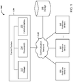
- the production system 100 includes a plurality of production devices 110 for processing workpieces, a production control system 120 for controlling operation of the production devices 110 and/or other system components to facilitate a mass production process, a communication network 130 for enabling communication among system components, and a production system storage component 140 for storing relevant data for the production system 100 (e.g. operational and/or control data relating to the production devices 110 and/or other aspects of the system 100).
- relevant data for the production system 100 e.g. operational and/or control data relating to the production devices 110 and/or other aspects of the system 100.
- control system 120 includes a control system storage component 122, one or more system processors 124, and a system communication component 126.
- the system processor 124 controls operation of the control system 120.
- the system processor 124 and processors at the production devices 110 cooperate to control operation of the system 100 (e.g. through determination and/or processing of control parameters and generation of control signals for operation and synchronization based on the control parameters).
- the storage component 122 (e.g. memory) can store data received from the production devices 110, data for coordinating operation of the production devices 110, property data in respect of each production device 110, etc.
- the storage component 122 can store computer programs executable by the system processor 124 to facilitate communication among and operation of the system components.
- the production system storage component 140 can be accessible via the communication network 130 and provided in addition to or in lieu of the control system storage component 122.
- the control system storage component 122 can store current operating data corresponding to current operation of the control system 120 (e.g. current position, speed, velocity, and/or acceleration of production tooling), and the production system storage component 140 can store data for future use.
- the storage component 140 can include third party data storage.
- the storage component 140 can store information about the production devices 110, including operating data, profile data (e.g., servo-motor profile data), motion data (e.g., tool motion data), part/workpiece/product data, etc. Such data can be stored in the storage component 140 for subsequent retrieval by the production devices 110 and/or control system 120, for example, through download via communication network 130.
- the communication network 130 can carry data to enable communication among system components (e.g. among the control system 120, production devices 110, storage component 140, and/or other devices/components), and can be a wired and/or wireless communication network.
- components of the system 100 can include wireless communication interfaces to enable wireless communication through communication network 130.
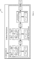
- the production device 110 includes a device control system 220, a sensor system 210, tooling 230, and a motion system 240.
- the device control system 220 includes a device processor 224, a device storage component (e.g. memory) 222, and a device communication component 226.
- the device control system 220 is operable to control operation of the production device 110, and can collect and store sensor, tooling, and motion data for the production device 110 in the device storage component 222 for operational use and/or for providing to the control system 120 through network 130 to facilitate electronic synchronization of production devices 110.
- the device storage component 222 can store data for operation of the production device 110 and/or to facilitate electronic synchronization.
- Example data can include, for example, operating data, part data, tool data, motion data, sensor data, etc.
- the sensor system 210 can include one or more sensors (e.g. range-finding, motion, vision systems, etc.) for collecting operational and/or environmental data for facilitating the production process.
- Each production device 110 can be equipped with a motion system 240 for movement of the production device 110 and/or components thereof (e.g. sensors, tooling, etc.).
- the motion system 240 can include, for example, one or more servo-motors and/or other actuators.
- the production devices 110 can be equipped with tooling 230 for engaging with and processing workpieces.
- Tooling 230 can be used for, for example, part handling, manipulation, transport, etc.
- the operation of tooling 230 can be controlled by the device control system 220 based on, for example, sensor data from the sensor system 210 and operational data for the production device 110 or other production devices 110 and/or system components.
- the tooling 230 can be in the form of, for example, one or more workpiece presentation tools for presenting the workpieces at predetermined locations for delivery and/or further processing and/or one or more workpiece processing tools for performing value-added operations on the workpieces.
- the workpiece presentation tools can be part of, for example, one or more tracks, carriers, conveyors, screws, indexer, actuators, or other devices for, for example, separating workpieces from other workpieces and delivery of the workpieces to a processing tool for subsequent processing.
- the presentation tools can be part of a carrier and configured to, for example, receive one or more workpieces, accelerate the workpieces toward a stop position (e.g. along a transport track) for a processing station, and present the workpieces at the processing position for processing by one or more processing tools of the station.
- Processing tools can be configured to conduct one or more value-added operations on or with the workpieces.
- the processing tools can be configured to manipulate a workpiece, assemble two or more workpieces together, reorient and/or reposition a workpiece for further processing, etc.
- processing tools can include, e.g. end effectors such as manipulators and/or grippers for part manipulation, assembly, reorientation, etc.
- the processing tools can be part of a pick-and-place robot and can be configured to, for example, unload one or more workpieces from a workpiece presentation tool (e.g. of a carrier); reorient (e.g. invert) the workpiece when unloaded; and load the workpiece when reoriented back into the workpiece presentation tool for subsequent processing.
- a workpiece presentation tool e.g. of a carrier
- reorient e.g. invert
- Machine-readable instructions stored in storage component 222 can cause the control system 220 (and/or 120) to execute various methods disclosed herein including generation of one or more signals (e.g., output data) useful in operation of the production devices 110.
- Such machine-readable instructions can be incorporated into one or more computer program products which can be stored on suitable medium or media.
- the machine-readable instructions can be executable by processor 224 and/or 124 for generation of signals useful in electronic synchronization of two or more operations carried out by the tooling 230 (e.g. by presentation and processing tools) of the production devices 110.
- the machine-readable instructions can be executable by the processor(s) for determination and/or selection of control parameters for operation of the tooling 230 and generate signals representative of the control parameters.
- the machine-readable instructions can be configured to cause processor 224 and/or 124 to generate signals useful in the electronic synchronization of, for example, the delivery of workpieces by a presentation tool and receipt of the workpieces by a processing tool; the processing steps performed by one or more processing tools; and/or delivery of a workpieces by the processing tool and receipt of the workpieces by the presentation tool.
- the synchronization of two or more operations performed by the tooling 230 of one or more production devices 110 can utilize electronic camming (e.g. instead of mechanical cams, gears, or linkages).
- electronic camming e.g. instead of mechanical cams, gears, or linkages.
- the use of such electronic synchronization can facilitate system flexibility and improve system performance relative to some more-conventional systems utilizing mechanical synchronization means.
- storage component 222 (and/or 122, 140) can hold data representative of one or more cam profiles to be used in the operation of the tooling 230 of one or more production devices 110.
- cam profile(s) can be in tabular form and can include corresponding positions representative of synchronized trajectories to be followed by the tooling 230 during operation.
- one tooling component 230 can be operated as a master device and another tooling component 230 can be operated as a slave device executing movements based on the execution of movements by the master device in order to substantially maintain synchronization between the slave device and the master device.
- the production devices 110 can include one or more master devices and one or more respective slave devices. For example, multiple slave devices can be electronically cammed with a master device.
- the machine-readable instructions can be configured to cause processor 224 and/or 124 to generate signals useful in electronic synchronization (e.g. camming) of the delivery of a workpiece by a presentation tool and of receipt of the workpiece by a processing tool (or another presentation tool).
- the machine-readable instructions can be configured to cause the processor(s) to generate signals useful in electronic synchronization of loading, separation, acceleration, and delivery of a workpiece by a presentation tool and of receipt of the workpiece by a processing tool.
- the machine-readable instructions can be configured to cause the processor(s) to generate signals useful in controlling movement of a workpiece along a delivery trajectory and controlling movement of a processing tool along a processing tool trajectory for electronic synchronization of the workpiece and processing tool.
- the machine-readable instructions can be configured to cause processor 224 and/or 124 to generate signals useful in controlling at least some aspect of the processing of a workpiece.
- processing can include one or more value-added operations that can be carried out by the processing tool.
- value-added operation can include, for example, inversion and/or repositioning of workpieces on a carrier.
- the machine-readable instructions may, for example, be configured to cause processor 224 (and/or 124) to generate signals useful in electronic synchronization of the processing of a workpiece and one or more operations associated with presentation and/or processing tools.
- the machine-readable instructions can be configured to cause the processor(s) to generate signals useful in controlling translation of a processing tool and rotation of the processing tool for electronic synchronization of the translation and rotation.
- one or more operations conducted by the presentation or processing tools can be under binary control rather than direct electronic synchronization.
- the triggering of an operation via a binary control signal can be dependent on the position of a master device and can still be based on a cam profile.
- the production devices 110 can include one or more servo-motors associated with tooling components 230, and the machine-readable instructions can be configured to cause processor 224 and/or 124 to generate signals useful in controlling the servo-motors according to a predetermined cam profile to carry out electronically synchronized operations according to the methods herein.
- the production devices 110 can include a numerically synchronized control architecture.
- transfer and presentation of workpieces e.g. by presentation tools
- the receiving of the workpiece e.g. by a processing tool or another presentation tool
- the loading, separating, accelerating, and delivering of workpieces can include a first computer numerically controlled operation and the receiving of the workpieces can include a second computer numerically controlled operation.
- the receiving of a workpiece can include a first computer numerically controlled operation and the processing of the workpiece can include a second computer numerically controlled operation.
- the processing of a workpiece can include a first computer numerically controlled operation and the delivery of the workpiece can include a second computer numerically controlled operation.
- the translation of a workpiece can include a first computer numerically controlled operation and the rotation of the workpiece can include a second computer numerically controlled operation.
- the first computer numerically controlled operation and the second computer numerically controlled operation can be electronically synchronized (e.g. electronically cammed).
- System 100a can be configured to carry out steps from processes disclosed herein.
- System 100a can receive workpieces and/or raw materials as inputs; progressively add value to them via processing tools; and discharge them either as discrete finished products, as unfinished products, or as rejected scrap (i.e., defective products).
- system 100a can receive the workpieces and/or materials from one or more feeders (e.g. of a feed device) for delivering workpieces and/or materials to another presentation tool (e.g. of an indexing device).
- the delivery from the feeders can be done directly or via a respective buffer.
- Each presentation tool or transfer device (e.g. carrier) of the system 100a can be numerically controlled and configured to deliver the materials and/or workpieces to one or more processing tools (e.g. of a processing device).
- Each processing tool can add value to a workpiece and/or material via one or more programmable process steps.
- a given processing tool can operate in parallel to and/or in series with one or more other processing tools and/or presentation tools.
- the system can include validation stations including validation devices configured to conduct inspections, checks, and/or tests on one or more of the workpieces.
- the validation stations can be located at, for example, one or more feeders, presentation tools, transfer devices, and/or processing tools. At these points, workpieces can be eliminated from the system as scrap if they do not meet one or more predetermined inspection criteria.
- Validation stations can be configured to conduct inspection, check, and/or test operations on one or more of workpieces that can be electronically synchronized with other devices, such as, for example, a master device of the production devices 110.
- the various elements described above can be controlled at least in part by software resources known as base software backplane.
- the backplane can be configured to permit various elements of the system to carry out various control functions including: management of inputs and outputs; management of local control tasks, including programmable process steps within processing tools and local inspection tasks within validation stations; communications between different elements in the system and communication with a human user via the operator interface.
- the system 100a can include a numerically synchronized control architecture.
- the feeders, presentation tools, processing tools, and transfer devices can be numerically controlled. Movement of workpieces and materials through the system can occur along programmable axes of motion, which can be either rotary or linear. Movement of tooling associated with the programmable process steps of processing tools can also take place along programmable linear and/or rotary axes of motion.
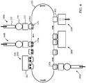
- the system 100 includes a transport track 150 supporting a plurality of carriers 152.
- Each carrier 152 comprises a pallet configured for holding at least one workpiece, and is movable along the track 150 (e.g. through one or more servo-drives) among a plurality of processing stations 160.
- Each processing station 160 includes one or more production devices 110 operable in electronic synchronization with each other, the carriers 152, and/or production devices 110 of other processing stations 160 for processing the workpieces.
- the processing stations 160 shown in Figure 4 include a first processing station 160a for transferring one or more workpieces 170 to each carrier 152 and a second processing station 160b for delivering and installing one or more parts (e.g. O-rings) onto the workpieces 170 held by the carrier 152 to form a workpiece assembly 170a.
- the processing stations 160 of the system 100 shown in Figure 4 further include a third processing station 160c for reorienting (e.g. inverting) the workpiece assembly 170a held by the carrier 152, and optionally repositioning the reoriented workpiece assembly 170a on the carrier 152 and/or assembling the reoriented workpiece assembly with another product part held by the carrier 152.
- the processing stations 160 further include a fourth processing station 160d for delivering and installing one or more additional product parts onto the reoriented/repositioned workpiece assembly 170a held by the carrier to form a second workpiece assembly 170b, a fifth processing station 160e for validating, testing, and/or inspecting (and/or performing some other operation) on the second workpiece assembly 170b held by the carrier 152, and a sixth processing station 160f for removing the second workpiece assemblies 170b from the carrier for discharge from the system 100, either as a successfully completed and validated finished product, as an unfinished product, or as a rejected defective product.
- a fourth processing station 160d for delivering and installing one or more additional product parts onto the reoriented/repositioned workpiece assembly 170a held by the carrier to form a second workpiece assembly 170b
- a fifth processing station 160e for validating, testing, and/or inspecting (and/or performing some other operation) on the second workpiece assembly 170b held by the carrier 152
- a sixth processing station 160f
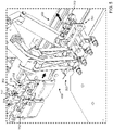
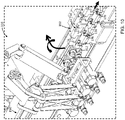
- each carrier 152 holds at least one workpiece 170 (e.g. in the form of workpiece assembly 170a) and is advanceable through a stop position along the track 150 (only a portion of which is shown in Figure 5 ) adjacent the workpiece inversion station 300.
- the station 300 includes a pick-and-place robot 310 for unloading one or more of the workpieces 170 from one or more carriers 152 at the stop position, inverting the unloaded workpieces 170, and loading the workpieces 170 when inverted back into the one or more carriers 152 at the stop position.
- the pick-and-place robot 310 includes at least one end effector 312 operable to engage (e.g. grip) the workpiece 170 on the carrier 152 at the stop position.
- the end effector 312 is translatable toward and away from the carrier 152 at the stop position for unloading the workpiece from the carrier 152 and loading the workpiece 170 back into the carrier 152.
- the end effector 312 is rotatable relative to the carrier 152 for inverting the workpiece 170 when unloaded (and held) by the end effector 312.
- each carrier 152 holds a plurality of the workpieces (e.g. two in the example illustrated), and a plurality of the carriers 152 (e.g. two in the example illustrated) are positionable at the stop position.
- the robot 310 is configured for unloading, inverting, and reloading the workpieces 170 held by each carrier 152 at the stop position (e.g. two workpieces from each carrier for a total of four workpieces in the example illustrated) simultaneously from the carriers 152 at the stop position.
- the robot 310 includes a plurality of the end effectors 312 (four in the example illustrated) operable simultaneously to engage (e.g. grip) and invert the workpieces 170 held by the carriers 152 at the stop position.
- the end effectors 312 are moveable among an unloading position (shown in Figure 6 ) adjacent the carriers 152 at the stop position for unloading the workpieces 170, one or more retracted positions (shown in, for example, Figures 5 , 7 , 9 , and 10 ) clear of a work envelope of the carriers 152 (e.g. to permit advancement of the carriers 152 toward and away from the stop position and rotation of the end effectors 312 while holding the workpieces 170), and a loading position (shown in Figure 8 ) adjacent the carriers 152 at the stop position for loading the workpieces 170 back into the carriers 152.
- an unloading position shown in Figure 6
- retracted positions shown in, for example, Figures 5 , 7 , 9 , and 10
- a loading position shown in Figure 8
- the workpiece 170 can be unloaded from and loaded back into the same location on the carrier 152 (e.g. a nest for holding the workpiece in both uninverted and inverted positions).
- the loading and unloading positions for the end effectors 312 can comprise a common position or adjacent positions in alignment with the location on the carrier 152 for unloading and loading the workpieces 170.
- each carrier 152 includes a plurality of first locations 154 for holding the workpieces 170 prior to inversion and from which the workpieces 170 are unloaded, and a plurality of second locations 156 for holding the workpieces 170 when inverted and into which the workpieces 170 are loaded after inversion.
- the second locations 156 are spaced apart from the first locations 154, and the unloading position is spaced apart from the loading position. Referring to Figure 6 , when in the unloading position, the end effectors 312 are in alignment with the first locations 154 for unloading the workpieces 170 therefrom.
- the end effectors 312 when in the loading position, are in alignment with the second locations 156 for loading the workpieces 170 therein.
- the second locations 156 are at an elevation below the first locations 154 and spaced apart from the first locations 154 toward the station 300 when the carriers 152 are at the stop position.
- each first location 154 comprises a first nest for holding the workpiece 170 prior to inversion
- each second location 156 comprises a second nest for holding the workpiece when inverted.
- the workpiece 170 can define a first product part
- the second nest can be at least partially defined by a second product part loaded into the carrier 152 at the second location 156 prior to arrival of the carrier 152 at the stop position (e.g. at an upstream processing station 160).
- the first product part (workpiece 170) can be mated with the second product part during loading of the workpiece 170 back into the carrier by the end effector 312 to form a product subassembly.
- the robot 310 includes a carriage 314 moveable toward and away from the carriers 152 (e.g. through operation of one or more servo-motors), and the end effectors 312 are mounted to the carriage to translate therewith for moving the end effectors 312 between the unloading, retracted, and loading positions.
- each end effector 312 is rotatable relative to the carriage 314 (through operation of corresponding servo-motors mounted to the carriage 314) by 180 degrees for inverting the workpieces when held by the end effector 312.
- each end effector is rotatable again by 180 degrees to reset the rotational orientation of the end effector 312 (e.g.
- each end effector 312 is rotatably relative to the carriage about a generally horizontal rotation axis that is generally perpendicular to the segment of the track 150 at the stop position.
- Each end effector 312 can include a pair of fingers moveable toward and away from each other for gripping a corresponding workpiece 170 between the fingers and releasing the workpiece 170 from between the fingers.
- control systems 120, 220 are configured to electronically synchronize operation of the carriers 152 and robot 310 to carry out the methods described herein for processing the workpieces.
- the end effectors 312 of the robot 310 are advanced to the unloading position in electronic synchronization with advancement of the carriers 152 (along the track 150) to the stop position to synchronize arrival of the carriers 152 at the stop position with arrival of the end effectors 312 at the unloading position.
- the carriers 152 arrive at the stop position prior to arrival of the end effectors 312 at the unloading position.
- the end effectors 312 when in the unloading position, the end effectors 312 are operated to simultaneously engage (e.g. grip) the workpieces 170 held by the carriers 152 at the stop position.
- the end effectors 312 are retracted from the unloading position away from the carriers 152 to unload the workpieces 170 from the carriers 152, and then advanced back toward the carriers 152 to the loading position to load the workpieces 170 back into the carriers 152.
- the end effectors 312 are retracted away from the unloading position to unload the workpieces 170 from corresponding first locations 154 on the carriers 152, and advanced to the loading position to load the workpieces 170 back on the carrier at corresponding second locations 156 on the carriers 152.
- the end effectors 312 are rotated relative to the carriers 152 by 180 degrees to invert the workpieces 170 held by the end effectors 312 in electronic synchronization with movement of the end effectors 312 from the unloading position to the loading position to load the workpieces 170 after inversion back into the carriers 152.
- rotation of the end effectors 312 for inverting the workpieces 170 is initiated during retraction of the end effectors 312 away from the unloading position (e.g. immediately after the workpieces 170 clear the carriers 152 for permitting interference free rotation), and terminates during advancement of the end effectors 312 toward the loading position (e.g. immediately prior to the workpieces 170 reaching the second nests).
- the movement of the end effectors 312 from the unloading position to the loading position comprises a generally continuous, uninterrupted translation of the end effectors 312.
- the rotation of the end effectors 312 for inverting the workpieces 170 comprises a generally continuous, uninterrupted rotation of the end effectors 312.
- the end effectors 312 are operated to release the workpieces 170, and the end effectors 312 are retracted away from the carriers 152 in electronic synchronization with advancement of the carriers 152 along the track 150 away from the stop position for the station 300 (and toward another stop position for another processing station 160 for further processing of the inverted workpieces 170).
- the end effectors 312 can then be rotated by 180 degrees to reset the rotational orientation of the end effectors 312 in preparation for another inversion cycle with another set of carriers.
- the inversion process is repeated continuously to invert workpieces held in subsequent carriers in a continuous mass production process.
Landscapes
- Engineering & Computer Science (AREA)
- Mechanical Engineering (AREA)
- Robotics (AREA)
- General Engineering & Computer Science (AREA)
- Manufacturing & Machinery (AREA)
- Quality & Reliability (AREA)
- Physics & Mathematics (AREA)
- General Physics & Mathematics (AREA)
- Automation & Control Theory (AREA)
- Automatic Assembly (AREA)
- Multi-Process Working Machines And Systems (AREA)
Applications Claiming Priority (1)
| Application Number | Priority Date | Filing Date | Title |
|---|---|---|---|
| US202163168158P | 2021-03-30 | 2021-03-30 |
Publications (3)
| Publication Number | Publication Date |
|---|---|
| EP4068021A1 true EP4068021A1 (fr) | 2022-10-05 |
| EP4068021C0 EP4068021C0 (fr) | 2026-02-11 |
| EP4068021B1 EP4068021B1 (fr) | 2026-02-11 |
Family
ID=80930457
Family Applications (1)
| Application Number | Title | Priority Date | Filing Date |
|---|---|---|---|
| EP22163904.0A Active EP4068021B1 (fr) | 2021-03-30 | 2022-03-23 | Systèmes d'inversion automatisés de pièces et procédés associés |
Country Status (2)
| Country | Link |
|---|---|
| US (2) | US11932497B2 (fr) |
| EP (1) | EP4068021B1 (fr) |
Families Citing this family (2)
| Publication number | Priority date | Publication date | Assignee | Title |
|---|---|---|---|---|
| US11932497B2 (en) * | 2021-03-30 | 2024-03-19 | Ats Corporation | Automated workpiece inversion systems and related methods |
| WO2025065093A1 (fr) * | 2023-09-26 | 2025-04-03 | Ats Corporation | Systèmes de filetage de pièces automatisé et procédés associés |
Citations (5)
| Publication number | Priority date | Publication date | Assignee | Title |
|---|---|---|---|---|
| JP2005046966A (ja) * | 2003-07-30 | 2005-02-24 | Toyota Motor Corp | 生産システム |
| US7845483B2 (en) * | 2006-07-25 | 2010-12-07 | Honda Motor Co., Ltd. | Conveying operation method and conveying operation device |
| US9904281B2 (en) | 2012-11-23 | 2018-02-27 | Transformix Engineering Inc. | Computer numerical control assembly or processing of components |
| US10018985B2 (en) | 2014-08-12 | 2018-07-10 | Transformix Engineering Inc. | Computer numerical control assembly or processing of components |
| EP3637091A1 (fr) * | 2017-06-07 | 2020-04-15 | SCREEN Holdings Co., Ltd. | Dispositif de transport, procédé de transport et système d'inspection |
Family Cites Families (3)
| Publication number | Priority date | Publication date | Assignee | Title |
|---|---|---|---|---|
| US5440943A (en) * | 1993-09-15 | 1995-08-15 | Intest Corporation | Electronic test head manipulator |
| SE527394C2 (sv) * | 2002-03-15 | 2006-02-28 | Renholmens Mek Verkst Ab | Brädvändare och förfarande för användning av brädor |
| US11932497B2 (en) * | 2021-03-30 | 2024-03-19 | Ats Corporation | Automated workpiece inversion systems and related methods |
-
2022
- 2022-03-17 US US17/697,627 patent/US11932497B2/en active Active
- 2022-03-23 EP EP22163904.0A patent/EP4068021B1/fr active Active
-
2024
- 2024-03-18 US US18/607,933 patent/US12330884B2/en active Active
Patent Citations (6)
| Publication number | Priority date | Publication date | Assignee | Title |
|---|---|---|---|---|
| JP2005046966A (ja) * | 2003-07-30 | 2005-02-24 | Toyota Motor Corp | 生産システム |
| US7845483B2 (en) * | 2006-07-25 | 2010-12-07 | Honda Motor Co., Ltd. | Conveying operation method and conveying operation device |
| US9904281B2 (en) | 2012-11-23 | 2018-02-27 | Transformix Engineering Inc. | Computer numerical control assembly or processing of components |
| US10018985B2 (en) | 2014-08-12 | 2018-07-10 | Transformix Engineering Inc. | Computer numerical control assembly or processing of components |
| EP3180663B1 (fr) * | 2014-08-12 | 2019-04-17 | ATS Automation Tooling Systems Inc. | Assemblage ou traitement de composants par commande numérique informatique |
| EP3637091A1 (fr) * | 2017-06-07 | 2020-04-15 | SCREEN Holdings Co., Ltd. | Dispositif de transport, procédé de transport et système d'inspection |
Also Published As
| Publication number | Publication date |
|---|---|
| EP4068021C0 (fr) | 2026-02-11 |
| US11932497B2 (en) | 2024-03-19 |
| US20220332519A1 (en) | 2022-10-20 |
| US12330884B2 (en) | 2025-06-17 |
| EP4068021B1 (fr) | 2026-02-11 |
| US20240308783A1 (en) | 2024-09-19 |
Similar Documents
| Publication | Publication Date | Title |
|---|---|---|
| US12330884B2 (en) | Automated workpiece inversion systems and related methods | |
| US12466070B2 (en) | Automated O-ring processing stations and related methods | |
| CN102284881B (zh) | 加工输送系统 | |
| JP6716562B2 (ja) | 部品のコンピュータ数値制御による組み立てまたは加工 | |
| CN104797994B (zh) | 对组件的计算机数控装配或处理的装置、系统及方法 | |
| EP2581178A1 (fr) | Système d'extraction de pièce, appareil robot et procédé de production d'un matériau à traiter | |
| US20250197130A1 (en) | Automated repitch system and related methods | |
| CN112157408A (zh) | 工业机器人双机协作搬运系统与方法 | |
| WO2025065093A1 (fr) | Systèmes de filetage de pièces automatisé et procédés associés | |
| US12565347B2 (en) | Automated syringe processing stations and related methods | |
| JP2020127996A (ja) | 工作機械、異物検知方法、および、異物検知プログラム | |
| CN115016400A (zh) | 自动化生产站和相关方法 | |
| JPH07259B2 (ja) | 被加工物の自動搬送装置 | |
| JP2021104491A (ja) | ワーク処理システム | |
| CN106392190A (zh) | 用于加工工件,特别是锯片的设备 | |
| Garrido et al. | New Motion Control approach for synchronized handling of complex parts | |
| CN121785275A (zh) | 一种ecu自动刷写产线控制系统及控制方法 | |
| CN111169979A (zh) | 机械手搬运方法以及系统 | |
| JP2001019153A (ja) | 物品の振り分け装置及び振り分け方法 | |
| HK1211092B (en) | Computer numerical control assembly or processing of components |
Legal Events
| Date | Code | Title | Description |
|---|---|---|---|
| PUAI | Public reference made under article 153(3) epc to a published international application that has entered the european phase |
Free format text: ORIGINAL CODE: 0009012 |
|
| STAA | Information on the status of an ep patent application or granted ep patent |
Free format text: STATUS: THE APPLICATION HAS BEEN PUBLISHED |
|
| AK | Designated contracting states |
Kind code of ref document: A1 Designated state(s): AL AT BE BG CH CY CZ DE DK EE ES FI FR GB GR HR HU IE IS IT LI LT LU LV MC MK MT NL NO PL PT RO RS SE SI SK SM TR |
|
| STAA | Information on the status of an ep patent application or granted ep patent |
Free format text: STATUS: REQUEST FOR EXAMINATION WAS MADE |
|
| 17P | Request for examination filed |
Effective date: 20230405 |
|
| RBV | Designated contracting states (corrected) |
Designated state(s): AL AT BE BG CH CY CZ DE DK EE ES FI FR GB GR HR HU IE IS IT LI LT LU LV MC MK MT NL NO PL PT RO RS SE SI SK SM TR |
|
| RAP3 | Party data changed (applicant data changed or rights of an application transferred) |
Owner name: ATS CORPORATION |
|
| REG | Reference to a national code |
Ref country code: DE Ref legal event code: R079 Ipc: B25J0015000000 Ref country code: DE Ref legal event code: R079 Ref document number: 602022030021 Country of ref document: DE Free format text: PREVIOUS MAIN CLASS: G05B0019418000 Ipc: B25J0015000000 |
|
| GRAP | Despatch of communication of intention to grant a patent |
Free format text: ORIGINAL CODE: EPIDOSNIGR1 |
|
| STAA | Information on the status of an ep patent application or granted ep patent |
Free format text: STATUS: GRANT OF PATENT IS INTENDED |
|
| RIC1 | Information provided on ipc code assigned before grant |
Ipc: B25J 9/00 20060101ALI20250520BHEP Ipc: B65G 47/248 20060101ALI20250520BHEP Ipc: G05B 19/418 20060101ALI20250520BHEP Ipc: B65G 47/90 20060101ALI20250520BHEP Ipc: B25J 15/00 20060101AFI20250520BHEP |
|
| INTG | Intention to grant announced |
Effective date: 20250530 |
|
| GRAJ | Information related to disapproval of communication of intention to grant by the applicant or resumption of examination proceedings by the epo deleted |
Free format text: ORIGINAL CODE: EPIDOSDIGR1 |
|
| STAA | Information on the status of an ep patent application or granted ep patent |
Free format text: STATUS: REQUEST FOR EXAMINATION WAS MADE |
|
| GRAP | Despatch of communication of intention to grant a patent |
Free format text: ORIGINAL CODE: EPIDOSNIGR1 |
|
| STAA | Information on the status of an ep patent application or granted ep patent |
Free format text: STATUS: GRANT OF PATENT IS INTENDED |
|
| INTC | Intention to grant announced (deleted) | ||
| INTG | Intention to grant announced |
Effective date: 20251009 |
|
| GRAS | Grant fee paid |
Free format text: ORIGINAL CODE: EPIDOSNIGR3 |
|
| GRAA | (expected) grant |
Free format text: ORIGINAL CODE: 0009210 |
|
| STAA | Information on the status of an ep patent application or granted ep patent |
Free format text: STATUS: THE PATENT HAS BEEN GRANTED |
|
| AK | Designated contracting states |
Kind code of ref document: B1 Designated state(s): AL AT BE BG CH CY CZ DE DK EE ES FI FR GB GR HR HU IE IS IT LI LT LU LV MC MK MT NL NO PL PT RO RS SE SI SK SM TR |
|
| REG | Reference to a national code |
Ref country code: CH Ref legal event code: F10 Free format text: ST27 STATUS EVENT CODE: U-0-0-F10-F00 (AS PROVIDED BY THE NATIONAL OFFICE) Effective date: 20260211 Ref country code: GB Ref legal event code: FG4D |
|
| REG | Reference to a national code |
Ref country code: DE Ref legal event code: R096 Ref document number: 602022030021 Country of ref document: DE |
|
| REG | Reference to a national code |
Ref country code: IE Ref legal event code: FG4D |
|
| PGFP | Annual fee paid to national office [announced via postgrant information from national office to epo] |
Ref country code: AT Payment date: 20260301 Year of fee payment: 5 |
|
| U01 | Request for unitary effect filed |
Effective date: 20260309 |
|
| U07 | Unitary effect registered |
Designated state(s): AT BE BG DE DK EE FI FR IT LT LU LV MT NL PT RO SE SI Effective date: 20260313 |