EP4068644A2 - Récupération de défaillance de faisceau pour équipements utilisateur (ue) de services de diffusion et de multidiffusion (mbs) - Google Patents
Récupération de défaillance de faisceau pour équipements utilisateur (ue) de services de diffusion et de multidiffusion (mbs) Download PDFInfo
- Publication number
- EP4068644A2 EP4068644A2 EP22164414.9A EP22164414A EP4068644A2 EP 4068644 A2 EP4068644 A2 EP 4068644A2 EP 22164414 A EP22164414 A EP 22164414A EP 4068644 A2 EP4068644 A2 EP 4068644A2
- Authority
- EP
- European Patent Office
- Prior art keywords
- mbs
- bfd
- beam failure
- gnb
- pdcch
- Prior art date
- Legal status (The legal status is an assumption and is not a legal conclusion. Google has not performed a legal analysis and makes no representation as to the accuracy of the status listed.)
- Granted
Links
Images


Classifications
-
- H—ELECTRICITY
- H04—ELECTRIC COMMUNICATION TECHNIQUE
- H04W—WIRELESS COMMUNICATION NETWORKS
- H04W24/00—Supervisory, monitoring or testing arrangements
- H04W24/04—Arrangements for maintaining operational condition
-
- H—ELECTRICITY
- H04—ELECTRIC COMMUNICATION TECHNIQUE
- H04B—TRANSMISSION
- H04B7/00—Radio transmission systems, i.e. using radiation field
- H04B7/02—Diversity systems; Multi-antenna system, i.e. transmission or reception using multiple antennas
- H04B7/04—Diversity systems; Multi-antenna system, i.e. transmission or reception using multiple antennas using two or more spaced independent antennas
- H04B7/06—Diversity systems; Multi-antenna system, i.e. transmission or reception using multiple antennas using two or more spaced independent antennas at the transmitting station
- H04B7/0686—Hybrid systems, i.e. switching and simultaneous transmission
- H04B7/0695—Hybrid systems, i.e. switching and simultaneous transmission using beam selection
- H04B7/06952—Selecting one or more beams from a plurality of beams, e.g. beam training, management or sweeping
- H04B7/06964—Re-selection of one or more beams after beam failure
-
- H—ELECTRICITY
- H04—ELECTRIC COMMUNICATION TECHNIQUE
- H04B—TRANSMISSION
- H04B7/00—Radio transmission systems, i.e. using radiation field
- H04B7/02—Diversity systems; Multi-antenna system, i.e. transmission or reception using multiple antennas
- H04B7/04—Diversity systems; Multi-antenna system, i.e. transmission or reception using multiple antennas using two or more spaced independent antennas
- H04B7/08—Diversity systems; Multi-antenna system, i.e. transmission or reception using multiple antennas using two or more spaced independent antennas at the receiving station
- H04B7/0868—Hybrid systems, i.e. switching and combining
- H04B7/088—Hybrid systems, i.e. switching and combining using beam selection
-
- H—ELECTRICITY
- H04—ELECTRIC COMMUNICATION TECHNIQUE
- H04L—TRANSMISSION OF DIGITAL INFORMATION, e.g. TELEGRAPHIC COMMUNICATION
- H04L5/00—Arrangements affording multiple use of the transmission path
- H04L5/003—Arrangements for allocating sub-channels of the transmission path
- H04L5/0048—Allocation of pilot signals, i.e. of signals known to the receiver
-
- H—ELECTRICITY
- H04—ELECTRIC COMMUNICATION TECHNIQUE
- H04L—TRANSMISSION OF DIGITAL INFORMATION, e.g. TELEGRAPHIC COMMUNICATION
- H04L5/00—Arrangements affording multiple use of the transmission path
- H04L5/003—Arrangements for allocating sub-channels of the transmission path
- H04L5/0053—Allocation of signalling, i.e. of overhead other than pilot signals
-
- H—ELECTRICITY
- H04—ELECTRIC COMMUNICATION TECHNIQUE
- H04W—WIRELESS COMMUNICATION NETWORKS
- H04W24/00—Supervisory, monitoring or testing arrangements
- H04W24/08—Testing, supervising or monitoring using real traffic
-
- H—ELECTRICITY
- H04—ELECTRIC COMMUNICATION TECHNIQUE
- H04W—WIRELESS COMMUNICATION NETWORKS
- H04W4/00—Services specially adapted for wireless communication networks; Facilities therefor
- H04W4/06—Selective distribution of broadcast services, e.g. multimedia broadcast multicast service [MBMS]; Services to user groups; One-way selective calling services
-
- H—ELECTRICITY
- H04—ELECTRIC COMMUNICATION TECHNIQUE
- H04W—WIRELESS COMMUNICATION NETWORKS
- H04W72/00—Local resource management
- H04W72/12—Wireless traffic scheduling
- H04W72/1263—Mapping of traffic onto schedule, e.g. scheduled allocation or multiplexing of flows
- H04W72/1273—Mapping of traffic onto schedule, e.g. scheduled allocation or multiplexing of flows of downlink data flows
-
- H—ELECTRICITY
- H04—ELECTRIC COMMUNICATION TECHNIQUE
- H04W—WIRELESS COMMUNICATION NETWORKS
- H04W72/00—Local resource management
- H04W72/20—Control channels or signalling for resource management
- H04W72/21—Control channels or signalling for resource management in the uplink direction of a wireless link, i.e. towards the network
-
- H—ELECTRICITY
- H04—ELECTRIC COMMUNICATION TECHNIQUE
- H04W—WIRELESS COMMUNICATION NETWORKS
- H04W72/00—Local resource management
- H04W72/20—Control channels or signalling for resource management
- H04W72/23—Control channels or signalling for resource management in the downlink direction of a wireless link, i.e. towards a terminal
- H04W72/231—Control channels or signalling for resource management in the downlink direction of a wireless link, i.e. towards a terminal the control data signalling from the layers above the physical layer, e.g. RRC or MAC-CE signalling
-
- H—ELECTRICITY
- H04—ELECTRIC COMMUNICATION TECHNIQUE
- H04W—WIRELESS COMMUNICATION NETWORKS
- H04W76/00—Connection management
- H04W76/10—Connection setup
- H04W76/19—Connection re-establishment
Definitions
- the subject matter disclosed herein relates to wireless communications. More particularly, the subject matter disclosed herein relates to systems and methods for recovering from a Multicast and Broadcast Services (MBS) beam failure incident.
- MBS Multicast and Broadcast Services
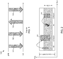
- FIG. 1 depicts the main operations of a NR Rel. 15 and a Rel 16 BFR procedure 100.
- the gNB may explicitly configure a set of beam failure detection-reference signal (BFD-RS) that may be used for the assessment of the serving beams quality, denoted by q 0 .
- BFD-RS beam failure detection-reference signal
- a User Equipment assumes the Reference Signal RS Quasi Co-Located (QCLed) with monitoring physical downlink control channel (PDCCH) belong to q 0 .
- the UE does not expect to be configured with more than two RS with radio resource control (RRC) parameter purpose that is set as beamFailure or both radio link monitoring (RLM) and beam failure.
- RRC radio resource control
- the purpose of the RRC parameter may be set as beamFailure only.
- a UE conducts measurements of the RSs and if the qualities of the RSs fall below a particular threshold, the UE physical layer (PHY) reports a beam failure instance (BFI) to a higher medium access control (MAC) layer of the UE.
- BFI beam failure instance
- MAC medium access control
- the threshold used for assessment may correspond to a default value of the threshold used for RLM and the threshold may be based on hypothetical block error rate (BLER) (10% BLER).
- a BFI reporting from UE physical layer to UE MAC layer may occur based on a particular periodicity.
- the periodicity may be the maximum period (i.e., 2 msec, shortest periodicity of BFD-RSs).
- the UE MAC should receive at least beamFailurelnstanceMaxCount BFI reports from UEs PHY within a time duration of beamFailureDetectionTimer. If the timer expires before the reported BFI reaches beamFailurelnstanceMaxCount, a BFI counter is reset to 0. This is beneficial to realize a behavior in which the reported BFI is to be contiguous, though triggering a beam failure by non-contiguous BFI reports may also be supported by the specification. Note that the timer is in units of a BFI reporting period from the UE PHY layer to the UE MAC layer.
- BFRQ Beam Failure Recovery Request
- the gNB may configure a candidate RS that may be used to recover the failed beam, denoted by q 1 in the specification.
- indices of a candidate beam RSs may be associated with different preamble IDs and/or random access (RA) occasions that may be used later to transmit BFRQ. This association may be beneficial to let the gNB know which candidate beam is preferred by the UE.
- the indexes of the candidate beam RSs may be associated with SCell ID. This allows the UE indicate the preferred candidate beam from any other serving cell as well, as described below.
- the gNB may configure the UE with a RSRP threshold to determine whether this beam may be reported as a candidate beam or not.
- a UE transmits the contention free-physical random access channel (CF-PRACH) associated with the preferred candidate beam if the quality of any of the measured candidate beams is higher than the provided RSRP threshold.
- CF-PRACH contention free-physical random access channel
- MAC-CE medium access control-control element
- a UE transmits BFR MAC-CE indicating the index of the failed cell and the index of the preferred candidate beam, if the quality of any of the measured candidate beams is greater than the provided RSRP threshold. If there are no PUSCH resources to carry MAC-CE, a UE may transmit a schedule request (SR) to request a resource.
- SR schedule request
- a UE is monitoring for a response of the gNB to determine whether the procedure has been successful.
- a UE is monitoring the PDCCH scrambled with a cell-radio network temporary identifier (C-RNTI) or MCS-C-RNTI in a configured search space (SS), through recoverySearchSpaceId, four slots after the slot contain a PRACH transmission.
- C-RNTI cell-radio network temporary identifier
- SS search space
- recoverySearchSpaceId four slots after the slot contain a PRACH transmission.
- a UE assumes that the gNB transmits the PDCCH using the indicated candidate beam. If the UE receives the PDCCH within beamFailureRecoveryTimer window, then the recovery is successful and uses the identified candidate beam for the subsequent transmission.
- the UE monitors PDCCH scrambled with RA-RNTI.
- DCI downlink control information
- NDI new data indication
- CFR Common Frequency Resource
- MBS BWP MBS BWP
- PRBs Physical Resource Blocks
- CFR is expected to provide the configurations of physical downlink shared channel (PDSCH), PDCCH, semi-persistent scheduling (SPS) PDSCH for MBS activities.
- PDSCH physical downlink shared channel
- PDCCH Physical Downlink Control Channel
- SPS semi-persistent scheduling
- the CFR common frequency resource
- SCS and CP the same numerology
- An example embodiment provides a method to manage beams in a wireless communication network in which the method may include: receiving, at a first device from a second device, a Physical Downlink Control Channel (PDCCH) and a Physical Downlink Shared Channel (PDSCH) for communications in a Common Frequency Resource (CFR); receiving, at the first device, a configuration for at least one Beam Failure Detection Reference Signal (BFD-RS); and detecting, at the first device, a Beam Failure Incident (BFI) of a first beam using the at least one BFD-RS configuration.
- the first device may include a User Equipment (UE), and the second device may include a Next Generation NodeB (gNB).
- UE User Equipment
- gNB Next Generation NodeB
- the configuration for the at least one BFD-RS provides explicit information about the at least one BFD-RS configuration by using higher-layer signaling.
- the configuration for the at least one BFD-RS provides implicit information to the first device about the at least one BFD-RS configuration based on a control resource set (CORESET) confinement within the CFR for a CORESET association with at least one search space set used for monitoring.
- detecting the beam failure incident of the first beam may include using a BFI counter that is separate from a unicast BFI counter.
- the method may further include autonomously connecting to a second beam by the first device based on detecting the BFI.
- the method may further include selecting, by the first device, the second beam based on at least one control resource set (CORESET) associated with the second beam, the at least one CORESET being associated with at least one beam.
- the method may further include communicating by the first device to the second device a Beam Failure Recovery Request (BFRQ) based on detecting the BFI.
- BFRQ Beam Failure Recovery Request
- communicating by the first device to the second device the BFRQ may using a Medium Access Control-Control Element (MAC-CE), an Uplink Control Information (UCI) or a Random Access Channel (RACH).
- communicating by the first device to the second device may further include communicating information relating to at least one of a cell identification of the BFI, an identification of the associated with a failed beam, or a candidate recovery beam.
- An example embodiment provides a wireless communication system that may include a Next Generation NodeB (gNB) and a User Equipment (UE).
- the gNB may be configured to send at least one Beam Failure Detection Reference (BFD-RS) configuration to the system.
- the UE may be configured to receive a Physical Downlink Control Channel (PDCCH) and a Physical Downlink Shared Channel (PDSCH) for communications in a Common Frequency Resource (CFR) and the at least one BFD-RS and may be configured to detect a Beam Failure Incident (BFI) of a first beam using the at least one BFD-RS configuration.
- PDCCH Physical Downlink Control Channel
- PDSCH Physical Downlink Shared Channel
- CFR Common Frequency Resource
- BFI Beam Failure Incident
- the configuration for the at least one BFD-RS is received by the UE and provides explicit information about the at least one BFD-RS configuration by higher-layer signaling.
- the configuration for the at least one BFD-RS includes a maximum number of BFD-RSs.
- the configuration for the at least one BFD-RS provides implicit information to the gNB about the at least one BFD-RS configuration based on a control resource set (CORESET) confinement within a common frequency resource (CFR) for the system or a CORESET association with at least one search space set used for monitoring.
- the UE may be configured to detect the beam failure incident of the first beam using a BFI counter that is separate from a unicast BFI counter.
- the UE may autonomously connect to a second beam based on detecting the BFI.
- the UE may select the second beam based on at least one control resource set (CORESET) associated with the second beam, the at least one CORESET being associated with multiple beams or a single beam.
- the UE communicates to the gNB a Beam Failure Recovery Request (BFRQ) based on detecting the BFI.
- the UE communicates to the gNB the BFRQ using a Medium Access Control-Control Element (MAC-CE), an Uplink Control Information (UCI) or a Random Access Channel (RACH).
- MAC-CE Medium Access Control-Control Element
- UCI Uplink Control Information
- RACH Random Access Channel
- the UE may be configured to communicates to the gNB information relating to at least one of a cell identification of the BFI, an identification of the associated with a failed beam, or a candidate recovery beam.
- a singular term may include the corresponding plural forms and a plural term may include the corresponding singular form.
- a hyphenated term e.g., "two-dimensional,” “pre-determined,” “pixel-specific,” etc.
- a corresponding non-hyphenated version e.g., "two dimensional,” “predetermined,” “pixel specific,” etc.
- a capitalized entry e.g., "Counter Clock,” “Row Select,” “PIXOUT,” etc.
- a non-capitalized version e.g., "counter clock,” “row select,” “pixout,” etc.
- first,” “second,” etc., as used herein, are used as labels for nouns that they precede, and do not imply any type of ordering (e.g., spatial, temporal, logical, etc.) unless explicitly defined as such.
- the same reference numerals may be used across two or more figures to refer to parts, components, blocks, circuits, units, or modules having the same or similar functionality. Such usage is, however, for simplicity of illustration and ease of discussion only; it does not imply that the construction or architectural details of such components or units are the same across all embodiments or such commonly-referenced parts/modules are the only way to implement some of the example embodiments disclosed herein.
- module refers to any combination of software, firmware and/or hardware configured to provide the functionality described herein in connection with a module.
- software may be embodied as a software package, code and/or instruction set or instructions
- the term "hardware,” as used in any implementation described herein, may include, for example, singly or in any combination, an assembly, hardwired circuitry, programmable circuitry, state machine circuitry, and/or firmware that stores instructions executed by programmable circuitry.
- the modules may, collectively or individually, be embodied as circuitry that forms part of a larger system, for example, but not limited to, an integrated circuit (IC), system on-a-chip (SoC), an assembly, and so forth.
- IC integrated circuit
- SoC system on-a-chip
- the beams used for MBS activities may be different than the beams used for unicast activities.
- the beams used for MBS activities may be expected to be wider to cover multiple UEs, while the beams used for unicast activities may be expected to be narrower and more directed toward specific UEs. Therefore, there should be processes to enable an MBS UE to detect a failure of a MBS beam and distinguish a MBS beam failure from a failure of unicast beam, which may be important for a MBS beam recovery process.
- a beam failure recovery for a MBS beam does not only aim to recover the failed MBS beam, but also aims to maintain the transmission for other UEs in the same MBS group. Therefore, more enhancements may be needed for the beam recovery of a failed MBS beam.
- the subject matter disclosed herein provides techniques for configuring MBS beam failure detection reference signals, which may include processes to explicitly or implicitly configure MBS beam failure detection reference signals (BFD-RSs) that differ from unicast BFD-RSs; processes to increase the maximum number of BFD-RS that may be configured; and how the MBS BFD-RSs may be associated with a MBS service/group ID.
- BFD-RSs MBS beam failure detection reference signals
- the subject matter disclosed herein also provides techniques for declaring a MBS beam failure, which may include flexible techniques for configuring counters/timers/thresholds that may be used to declare a MBS beam failure that differs from similar techniques used for unicast operations.
- a process of declaring a MBS beam failure is independent of beam failure declaration process in unicast case.
- the mutual impact between the unicast beam failure process and MBS beam failure process is also considered herein. Accordingly, different MBS beam failure processes may be defined for different MBS services/groups.
- a transparent recovery process may include configurations that allow a UE may autonomously recover from a beam failure without gNB involvement.
- a MBS search space may be associated with multiple control resource sets (CORESETs) to indicate potential candidate beams that may be used for beam recovery.
- the MBS search space may be associated with a single CORESET, but with multiple transmission configuration indication-states ( TCI-States ) to indicate the potential candidate beams for recovery.
- a UE may indicate a failure of MBS beams to the gNB through, for example, a MAC-CE process, an uplink control information (UCI), and/or a Random Access Channel (RACH), and to identify a candidate MBS beam. Additional information that may also be provided may include an ID of a MBS service/group. In one embodiment, recover may be provided by switching between different MBS scheduling schemes. Unless stated otherwise, the transparent and non-transparent recovery processes may apply to a SpCell, a PCell, a PSCell, and/or a SCell.
- UCI uplink control information
- RACH Random Access Channel
- a gNB may configure a UE using a different beam failure detection reference signal (BFD-RS).
- BFD-RS beam failure detection reference signal
- Such a configuration may be realized either explicitly or implicitly. That is, a gNB may explicitly or implicitly configure the UE with a different BFD-RS for a unicast beam failure and for a MBS beam failure.
- a gNB may explicitly provide a UE with MBS BFD-RSs.
- a gNB may provide a UE with a list of BFD-RS for MBS beams through higher-layer signaling, such as a RRC parameter MBS-failureDetectionResourcesToAddModList, which provides a list of reference signals for detecting MBS beam failure and/or radio link failure (RLF).
- RLF radio link failure
- a gNB may indicate the purpose of BFD-RS for unicast beam failure detection, and/or RLF, and/or MBS beam failure detection through higher-layer signaling.
- additional purposes such as "MBS-beamFailure" may be added to the existing RRC parameter purpose to indicate to the UE that the purpose of an associated reference signal is for unicast beam failure and/or RLF, or MBS beam failure. Additional values may be included to cover other combinations, such as MBS beam failure and RLF.
- the purpose parameter may be configured for unicast beam failure or MBS beam failure.
- the purpose parameter may optional be for UEs configured with MBS and additional RRC parameter, such as purpose-MBS may be introduced to select from a MBS beam failure, a unicast beam failure, or both.
- RRC parameter such as purpose-MBS
- a UE does not expect to be configured with both RRC parameters, ( purpose and purpose-MBS ) for the same cell.
- RadioLinkMonitoringConfig For explicit configuration, higher-layer parameters may be included in IE RadioLinkMonitoringConfig to indicate the purpose of the configured BFD-RS.
- An example IE RadioLinkMonitoringConfig in the pseudo code below shows some examples of the aforementioned RRC parameters. Note that not all the new aforementioned RRC parameters need be present.
- a gNB may implicitly provide a UE with different BFD-RSs for MBS beams in the absence of an explicit indication, or in combination with an explicit indication.
- the condition(s) under which a UE may implicitly derive the BFD-RS for MBS beams may be predefined, i.e., provided in the specification. For example, if a gNB provides N BFD-RS(s) for MBS beams, a UE may determine up to additional M BFD-RS(s) for MBS beams. This may achieve balance between signaling overhead and flexibility at the gNB because it may be expected to use more MBS beams than just unicast beams.
- a gNB may also provide value of N and M through higher layer signaling. If N is equal to zero, the aforementioned condition becomes: in case of the absence of explicit indication BFD-RS, a UE may determine MBFD-RS(s) implicitly.
- a gNB may indicate whether an explicit indication of BFD-RS may only be used or whether an explicit indication may be combined with an implicit indication through higher-layer signaling.
- a gNB may use higher-layer signaling to indicate to a UE which approach is used to provide/determine BFD-RS for MBS beams.
- a RRC parameter MBS_BFD_indication may be set to explicit, implicit, or a combination to indicate whether the BFD-RS(s) for MBS beams are signaled explicitly, determined implicitly, or combination of both.
- a UE may apply rules that are similar to the rules used for a unicast beam in Clause 6 in 3GPP TS 38.213: "Physical layer procedures for control," Rel. 16, V16.4.0. More specifically, a UE may determine BFD-RS for MBS beam to include periodic CSI-RS resource configuration indexes with same values as the RS indexes in the RS sets indicated by TCI-State for respective CORESETs that the UE uses for monitoring MBS PDCCH and, if there are two RS indexes in a TCI state, the set includes RS indexes configured with qcl-Type set to "typeD" for the corresponding TCI states.
- a UE may only assess the MBS beam quality using BFD-RSs that are QCLed with the DMRS of a MBS PDCCH monitored by the UE.
- a UE may only use BFD-RSs that have the same TCI-State of the CORESET in which a MBS PDCCH may be transmitted.
- the RSs that have the same TCI-State of the CORESET associated with this SS may only be considered for BFD-RSs for MBS beam assessment, but not for unicast beams.
- a gNB may explicitly or implicitly label which CORESETs may be used to determine BFD-RS(s) for a MBS beam using one, or combination, an explicit RRC parameter in CORESET configurations or implicitly by containment/association in/with CFR.
- a gNB may explicitly indicate the TCI-State of which particular CORESETs may be used for BFD-RS. For example, higher layer signaling such as a RRC parameter, MBS-reference may be included as part of ControlResourceSetld IE. If a gNB sets to MBS-reference to true, a UE may use the RS indicated by TCI-State of the CORESET to determine the BFD-RS for MBS beams. If not configured, or MBS-reference is set to false, a UE may not use the RS indicated by TCI-State of this CORESET to determine the BFD-RS for MBS beams.
- a gNB may explicitly indicate to a UE which particular CORESET(s) may be used to determine BFD-RS for MBS beams.
- a UE may use a CORESET associated with particular SS to determine the BFD-RS for MBS beams. That is, a gNB may explicitly indicate the SS having a CORESET that may be used to determine a BFD-RS for MBS beams. In one embodiment, a gNB may explicitly indicate to a UE which SS may be used through higher-layer signaling, such as a RRC parameter MBS-reference may be included as part of a SearchSpace IE. If a gNB sets a MBS-reference to be true, a UE may use the RS indicated by the TCI-State of the CORESET associated with the SS to determine the BFD-RS for MBS beams. If not configured, or MBS-reference is set to be false, a UE may not use the RS indicated by TCI-State of the CORESET associated with the SS to determine the BFD-RS for MBS beams.
- a UE may use the RS indicated by TCI-State of the CORESET associated with this SS to determine the BFD-RS for MBS beams. That is, if a SS configuration includes any new DCI formats for MBS, the CORESET associated with the SS may be used to determine the BFD-RS for MBS beams.
- a UE may use the RS indicated by TCI-State of the CORESET associated with this SS to determine the BFD-RS for MBS beams.
- DCI that schedules or triggers MBS transmission
- CRC cyclic redundancy check
- the UE may use the RS indicated by TCI-State of the CORESET associated with this SS to determine the BFD-RS for MBS beams.
- SCS new common SS
- any CORESET fully confined within MBS CFR may be used by a UE to determine the BFD-RS of MBS beams.
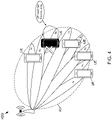
- FIG. 2 depicts two example CORESETs in which a CORESET 201 is not fully confined within the MBS CFR, whereas a CORSET 202 is fully confined within the MBS CFR. If the number of CORESETs confined within MBS CFR is greater than particular threshold, a UE may be expected to use RS indexes indicated by TCI-State of the CORESETs in ascending/descending order of their ID until reaching the threshold. Additional details are provided below regarding to determine/indicate that threshold.
- the CORESETs may be used to carry MBS PDCCH or not to carry MBS PDCCH. Also, other rules may be applied to determine which CORESETs may be used to determine the BFD-RSs for MBS beams.
- the CORESETs associated with the SSs in which a UE may monitor MBS PDCCH may be used by the UE to determine BFD-RSs for MBS beams.
- the CORESET may not be fully confined within CFR, which may be the case when a Point-to-Multipoint (PTM) scheme 2 is, for example, used to schedule MBS PDSCH.
- PTM Point-to-Multipoint
- CORESETs of search spaces associated with MBS CFR may be used to determine the BFD-RS for MBS beams.
- a MBS CFR is defined as a MBS BWP or is defined as a MBS region of contiguous RBs
- the CORESETs of the search spaces configured by PDCCH-config for MBS may be used to determine the BFD-RS for MBS beams.
- the CORESETs configured by PDCCH-config for MBS can be used to determine the BFD-RS for MBS beams.
- a UE When the number of the configured CORESETs that are associated with a MBS CFR is greater than particular threshold, a UE may be expected to use RS indexes indicated by TCI-State of the CORESETs in an ascending or a descending order of their ID until reaching the particular threshold. Additional details are provided below regarding how to determine/indicate a threshold. Also, other rules may be applied to determine which CORESETs may be used to determine the BFD-RSs for MBS beams.
- a UE In NR Rel. 15/16, a UE expects to be configured with at most two BFD-RSs for unicast beam per BWP for the purpose beamFailure or both (beam failure + RLM).
- a new threshold may be defined for the number of BFD-RS for MBS, which may be denoted herein as N MBS_LR in which "LR" stands for link recovery.
- the value of N MBS_LR may be predefined, provided in the specification, or indicated through higher-layer signaling. For example, N MBS _ LR may be equal to two BFD-RSs for MBS beams.
- a UE may indicate to a gNB the maximum supported number of BFD-RSs for MBS beams. In this case, a UE does not expect a gNB to configure the UE with BFD-RSs for MBS beams greater than the indicate value.
- Table 5-1 in 3GPP TS 38.213 may be added to Table 5-1 in 3GPP TS 38.213: "Physical layer procedures for control," Rel. 16, V16.4.0.
- Table 5-1 in 3GPP TS 38.213 provides the thresholds that define the maximum number of RSs that maybe configured for RLM and unicast beam failure ( N LR-RLM ) from which ( N RLM ) RSs may be used from RLM.
- the additional column may be for N MBS-LR-RLM to provide the maximum number of RSs that may be used for MBS beam failure, unicast beam failure and RLM.
- N LR-RLM may be interpreted as the maximum number of RS for a unicast beam and RLM, as same as in NR Rel. 15/16. Table 1.
- a UE may assume that set of BFD-RSs for a unicast beam and the set of BFD-RSs for a MBS beam are disjoint sets, i.e., the same RS may not be used for both a unicast beam and a MBS beam.
- a gNB configures the same BFD-RS for unicast beams and MBS beams
- a UE may not count this RS towards the maximum number of BFD-RSs for MBS beams. Instead, this BFD-RS is counted towards the maximum number of BFD-RSs for unicast beams.
- the BFD-RSs may also depend on the MBS service, which may be beneficial if a UE is a member in multiple MBS groups and a gNB uses different beams for different MBS services/groups. Therefore, failure of the MBS beam of particular service or group does not necessarily mean the failure of the MBS beams of other services or groups. To this end, if a gNB provides a UE with MBS BFD-RSs, a gNB may also provide the identity of the associated MBS group or service.
- the example MBS-BFD-RS IE below shows how to associate MBS BFD-RS with MBS service/group ID. Note that similar configurations may be provided as part of other IEs, such as RadioLinkMonitoringConfig IE. Also, an additional RRC parameter may be included for other functionality, such as purpose to indicate whether the indicated RS is for beam failure only, RLF or both.
- the maximum number of MBS BFD-RS for all configured MBS services/groups may be predefined, i.e., provided in the specification, or configured through higher-layer signaling, or indicated by a UE through capability signaling, or derived based on the number of configured MBS services/groups.
- the field MBS_group_serivce indicates the MBS service(s)/group(s) associated with the indicated BFD-RS.
- the same BFD-RS may be associated with multiple MBS services/groups up to the maximum number of configured MBS services/groups ( maxMBS_group_services ) .
- maxMBS_group_services may be predefined, i.e., provided in the specification, or configured through higher-layer signaling, or indicated by the UE through capability signaling, or derived based on the number of configured MBS services/groups.
- the following is example pseudo code for an IE for associating BFD-RSs with a MBS service/group.
- a physical layer of a UE reports separate beam failure instances (BFI) of MBS beam failure instances to a higher layer of the UE that differ from the BFI of unicast beam failure instance. This may enable the higher layer of the UE to take the corrective action based on which beam (a unicast beam, a MBS beam, or both) fails.
- BFI beam failure instances
- V16.4.0 may be applied, i.e., the physical layer of a UE informs the higher layer of the UE if the quality of MBS beam may be worse than particular threshold with a periodicity equal to the max (the smallest periodicity of BFD-RSs for MBS, N msec), in which N may be predefined or provided through higher-layer signaling.
- a gNB may configure a UE with another threshold, e.g., denoted herein by Q MBS, LR , to assess the quality of MBS beam differ from the threshold Q out, LR used for assessment of a unicast beam.
- Q MBS, LR may be based on a hypothetical BLER and a gNB may provide which threshold value may be applied.
- another RRC parameter similar to rlmInSyncOutOfSyncThreshold may be used. If absent, a UE applies the same hypothetical BLER threshold used for the threshold of unicast beam.
- MBS beam quality assessment may be used for the assessment of MBS beam quality that differ from the metrics used for a unicast beam quality assessment, e.g., for example, RSRP, SINR, etc., and the associated threshold value may be provided to a UE through higher-layer signaling.
- the indication periodicity of the MBS beam failure instance may be as same as, or different from, the indication periodicity of the unicast beam failure instance.
- FIG. 3 is a flowchart of an example embodiment of a process 300 for two independent processes that may be run simultaneously by a UE for a legacy unicast-beam-failure detection and for a MBS beam-failure detection according to the subject matter disclosed herein. Details regarding impacts of unicast and MBS beam-failure detection processes on each other are provided below.
- the process 300 starts at 301.
- a PHY layer of a UE reports a beam failure instance to a higher layer of the UE.
- the UE or a higher layer of the UE determines whether the beam failure instance is based on a unicast beam failure or a multicast beam failure. If the beam failure instance is based on a unicast beam failure, flow continues to 304 where the UE applies a legacy beam recovery process. Flow continues to 305, where the process ends.
- the UE may start a dedicated timer for MBS beam failure, e.g., MBS-beamFailureDetectionTimer.
- MBS-beamFailureDetectionTimer e.g., MBS-beamFailureDetectionTimer.
- a gNB may configure the UE with the MBS-beamFailureDetectionTimer.
- the value of the MBS-beamFailureDetectionTimer may be configured by the gNB through higher-layer signaling provided by a RRC from the gNB to the UE.
- the value of the MBS-beamFailureDetectionTimer may be defined relative to the reporting period of MBS beam failure instance.
- the value of the MBS-beamFailureDetectionTimer is defined in the specification, and the timer is running at the UE based on the definition in the specification. In yet another embodiment, if the value of the MBS-beamFailureDetectionTimer has not been provided, the UE may apply the same value as the unicast beamFailureDetectionTimer relative to the reporting period of MBS failure instance.
- a dedicated MBS-BFI-Counter may be incremented by the UE or a higher layer of the UE by one for each reported MBS beam failure instance.
- Flow continues to 308 where the UE or a higher layer of the UE determines whether the MBS-BFI-Counter has reached a maximum value.
- the gNB may provide a UE with maximum value of the MBS-BFI-Counter through higher-layer signaling.
- a UE may assume the maximum value for the MBS-BFI-Counter is equal to the corresponding counter of the unicast beam, if it is not provided by gNB.
- MBS beam failure detection process runs independent of the unicast beam failure detection process, there may be impacts on each respective beam failure detection process. For example, if a UE detects a unicast beam failure, i.e., the maximum number of unicast beam failure instances is reached, but the UE does not detect a MBS beam failure yet, then the UE may declare the failure of both unicast and MBS beams. The same may be applied if a UE detects a MBS beam failure before a unicast beam failure. That is, if a UE detects a unicast beam failure or a MBS beam failure, the UE may declare beam failure on both beams. In some cases, this may be beneficial if, for example, the recovery processes of MBS beams and unicast beams are different, then a UE may trigger both schemes if the failure of a MBS beam or a unicast beam is detected.
- a MBS beam failure detection process may include a dedicated MBS-beamFailureDetectionTimer and a MBS-BFI_counter , the same timer and/or the same counter may be used for unicast and MBS beam failure detection.
- one timer may be used for both processes. In such a situation, the timer may be started/restarted if the PHY layer of a UE reports beam failure instance of a unicast beam or of a MBS beam. Upon the expiry of the timer, both the unicast BFI-counter and the MBS-BFI-counter may be set to zero.
- a UE may use the same counter for unicast beam failure instances and MBS beam failure instances.
- a UE may increment the counter by "1" upon the reception of beam failure instance report from a PHY of a UE regardless it is for a unicast beam failure or a MBS beam failure.
- beam failure of both unicast beams and MBS beams may be declared.
- MBS beam-failure instances may differ from one MBS service/group due to different reliability and latency requirements. This may be provided through higher-layer signaling, as shown by the example pseudo code below.
- a similar approach may also be applied for the threshold used for declaring beam failure, e.g., a hypothetical BLER in which each MBS service/group may be associated with different thresholds for declaring beam failure.
- the different thresholds for different MBS services/groups may be able accommodate different liabilities and latencies requirements for each MBS service so that a UE may run independent MBS beam failure detection processes for the different MBS services/groups.
- a gNB may configure the different thresholds separately.
- One straight forward extension may be to have parallel beam failure detection processes running at the same time in which a failure of the MBS beam associated with particular MBS service does not affect the beam failure process of another MBS service.
- declaring a beam failure for a particular MBS service may trigger a beam failure of other MBS services even though the maximum number of beam failure instance of the MBS services have not been reached yet.
- a UE may determine which MBS service to declare beam failure due to a beam failure of another MBS service based on rules and/or based on configurations. For example, if MBS services are determined according to their priorities, then if a beam failure is declared for a particular MBS service having a certain priority level, then the beams of all other MBS services having higher priority levels may be assumed to also be failed.
- FIG. 4 depicts a system 400 in which multiple narrow beams b 0 -b 7 are used to serve a group of MBS UEs instead of using a wide beam covering all of the UEs of the MBS group.
- a virtual beam 401 is indicated that shows the MBS UE group intended to be covered by a MBS.
- the different (actual) beams b 0 -b 7 may be transmitting the same content or different contents.
- each beam may carry different MBS PDCCH in which each PDCCH indicates the same MBS PDSCH downlink assignment, but each MBS PDCCH provides a different QCL parameter of the scheduled MBS PDSCH.
- Other parameters of MBS PDSCH may vary as well from beam to beam, such as TDRA, FDRA, MCS, etc.
- a UE may autonomously switch to another beam that is determined to be used for the same MBS service. For example, this is depicted in FIG. 4 in which the UE shown in black detects a failure of MBS beam b 5 (indicated by an "X") and also determines that beam b 6 may be a good replacement beam. In this transparent recovery process, the blackened UE autonomously switches from beam b 5 to beam b 6 .
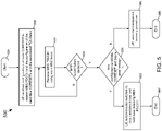
- FIG. 5 is a flowchart of an example embodiment of a process for a transparent recovery process 500 according to the subject matter disclosed herein.
- the process 500 starts of 501.
- a UE receives configurations of a default/main CORESET and the TCI-State that the UE should apply to receive MBS PDCCH, which corresponds to beam b 5 in FIG. 4 for this example.
- the UE may be provided with candidate beams for the reception of MBS PDCCH upon the failure of beam associated with the default/main CORESET. This corresponds to, for example, candidate beams b 0 -b 4 , b 6 and b 7 in FIG. 4 . Additional details are provided below regarding how to provide configurations of the main beam and candidate beams.
- the UE continues to use the beam associated with default/main CORESET. Flow continues to 504 where it is determined whether a MSB beam failure has been declared. If not flow returns to 503. If, at 504, a MSB beam failure has been declared, flow continues to 505 where the UE assesses the quality of the candidate MBS beams. Additional details are provided on how such assessment may be performed below. If a good candidate beam is identified at 505, flow continues to 506 where the UE autonomously switches to the good candidate beam to continue the reception of MBS PDCCH. Flow then continues to 507 where the process ends.
- flow continues to 508 where the UE may start non-transparent recovery process, which is described below. Flow then continues to 509 where the process ends.
- the UE may autonomously select another recovery beam from the candidate beam set, e.g. ⁇ b 0 , b 1 , b 2 , b 3 , b 4 , b 6 , b 7 ⁇ in FIG. 4 .
- the new beam for example, beam b 6 in FIG.
- the failed beam b 5 is added to the candidate beam set, which becomes the beam set ⁇ b 0 , b 1 , b 2 , b 3 , b 4 , b 5 ,b 7 ⁇ after b 6 has been removed from the candidate beam set. It may be beneficial to make such differentiation between the active beam labeled by "default/main beam" and the candidate beams set because this may determine how different beam are assessed and which RSs may be used to determine their quality, as described below.
- the RS associated with the main beam may be used as a BFD-RS.
- the UE may start using the default beam, which is determined based on the rules described below.
- the default beam may be the beam that UE assumes for the reception of DL MBS transmission, e.g., MBS PDCCH, after receiving the configurations or the MAC-CE activating particular TCI-State command.
- the UE may use the TCI-State of that beam to determine the set of BFD-RSs.
- the default beam fails and the UE identifies another beam to be used for the reception of DL MBS transmission, e.g., MBS PDCCH, then the later-identified beam is labeled as the main beam.
- the UE uses the TCI-State of this main beam to update both sets of BFD-RSs and candidate beam RSs.
- the explicit configurations of BFD-RSs may be realized using the aforementioned processes, or any other process, to explicitly provide the BFD-RSs of at least the default beam. If the UE changes the default beam to another beam, the set of BFD-RSs may be updated as described below.
- Such labeling is, however, not important as long as the UE may determine which respective RSs may be used to assess the quality of the serving and candidate beams to declare beam failure and determine the best recovery beam.
- the techniques disclosed herein may be applied on different MBS scheduling schemes, although focus is primarily on a point-to-multipoint (PTM) scheme 1 that uses a group common-physical downlink control channel (GC-PDCCH) to schedule MBS PDSCH for a group of MBS UEs.
- PTM point-to-multipoint
- GC-PDCCH group common-physical downlink control channel
- the search space of MBS may be associated with multiple CORESETs that may be associated with different TCI-States that may be determined by MAC-CE and/or RRC configurations.
- a UE is monitoring a CORESET with particular TCI-State
- other UEs in the same MBS group are expected to be monitoring other candidate CORESETs associated with the same/different SS based on their TCI-states, which can in general be different.
- This may allow a gNB a flexibility to configure the different CORESETs to occupy different time/frequency resources, and may significantly simplify the DL beam construction operation on the gNB side.
- different MBS beams may carry different MBS PDCCH in CORESETs that occupy different time/frequency resources. Consequently, a gNB may schedule different MBS PDSCHs for the same MBS service on different beams targeting different UEs in the same MBS group.
- the SearchSpace IE provides a UE with the monitoring periodicity of PDCCH and the first symbol within the slot to monitor PDCCH from where the CORESET starts.
- a gNB may indicate time offset between the CORESETs to ensure no overlapping at least in the time domain.
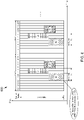
- FIG. 6 depicts an example embodiment of a MBS SS 600 having multiple CORESETs associated with different beams that have no overlapping in the time domain according to the subject matter disclosed herein.
- an example monitoring periodicity is set to one slot and PDCCH monitoring starts from OFDM symbol 4.
- the SS 600 may be associated with three CORESETs having different TCI-States, i.e., beam #0, beam #1 and beam #2.
- the UEs monitoring beam b 0 should use the CORESET #0 that starts from OFDM symbol 4 having a duration of 3.
- the UEs monitoring beam b 1 should use the CORESET #1 that starts from OFDM symbol 7 having a duration of 2.
- the UEs monitoring beam b 2 should use the CORESET #2 that starts from OFDM symbol 9 having a duration of 3.
- the offset value for CORESETs associated with different beam may be derived according to rules. For example, a UE may assume that the CORESETs associated with different beams are contiguous in time as shown FIG. 6 depending on the beam index. Alternatively, an offset value may be indicated through higher-layer signalling as part of, for example, a SearchSpace IE or a ControlResourceSet IE. The offset may be relative to the first OFDM symbol with the slot containing the monitoring occasion or relative to the indicated first symbol within the slot to monitor PDCCH, as shown in FIG. 6 .
- the SS 600 associated with MBS activities may be linked to multiple CORESETs, as shown in example pseudo code for SearchSpace IE below.
- a gNB may provide a list of the associated CORESET IDs. That is, the MBS search space may be associated with multiple CORESETs each having different TCI-States. Only one CORESET may be used at a time and the CORESET used may be determined according rules. For example, a UE may use the CORESET having the lowest/highest ID as the default CORESET that the UE uses for the reception of MBS PDCCH.
- the size of the list maxNrofCORESETs may be predefined, i.e., provided in the specification, or the UE indicates the size of the list to a gNB as part of capability signaling for the UE.
- Example pseudo code follows for a gNB to provide a list of CORESETs to a UE.
- a gNB may use the RRC parameter controlResourceSetId in the same approach as NR Rel. 15/16 to indicate only the ID of one CORESET, which may be used as the default/main CORESET.
- the gNB may provide a UE with other IDs of candidate CORESET that may be used upon the beam failure of the default/main CORESET through other higher-layer signaling, such as RRC parameter Candidate-controlResourceSetId.
- the maximum number of the candidate CORESETs that may be configured may predefined, i.e., provided in the specification, or a UE indicates the maximum number of candidate CORESETs to a gNB as part of the capability signaling of the UE.
- a gNB may use the RRC parameter controlResourceSetId in a same approach as NR Rel. 15/16 to indicate just the ID of one CORESET that may be used as the default/main CORESET. Then, the UE may derive the IDs of the candidate CORESETs according to rules. For example, the CORESETs having consecutive IDs starting from the ID of default/main CORESET + 1 to the CORESET ID that is the min(highest configured CORESET ID, ID of default/main CORESET + maximum number of the candidate CORESETs).
- the maximum number of the candidate CORESETs that may be configured may be predefined, i.e., provided in the specification, configured through higher-layer signaling or a UE indicates the maximum number of the candidate CORESETs to a gNB as part of capability signaling of the UE.
- a UE may determine the set of MBS BFD-RSs to include RS indexes with same values as the RS indexes in the RS sets indicated by TCI-State for default/main CORESETs that the UE uses for monitoring MBS PDCCH.
- a UE may only assess the MBS beam quality using BFD-RSs that are QCLed with the DMRS of MBS PDCCH that are currently monitored by the UE. In other words, if a UE autonomously switches to the new beam, then RSs that have same TCI-State of the beam may be added to the set of MBS BFD-RSs. On the other hand, RSs that have same TCI-State of an old failed beam may be excluded from the set of MBS BFD-RSs.
- the UE may assume that default/main CORESET is the CORESET having an activated TCI-State that is QCLed with the explicitly indicated BFD-RS for MBS beam. That is, the CORESET having activated TCI-State that is QCLed with any of the explicitly indicated BFD-RSs for MBS beams may be assumed to be the default/main CORESET for the reception of MBS beams.
- the BFD-RS used to assess the MBS beam quality may be QCLed with the DMRS of MBS PDCCH.
- a UE may apply some rules to determine which CORESET to use as default/main CORESET. For example, a UE may assume that the CORESET having the lowest/highest ID as the default CORESET that the UE may use for the reception of MBS PDCCH.
- the previously described processes to determine the default/main beam and the associated candidate beam list may be applied only once upon receiving the configurations or the activation MAC-CE with new TCI-State. For example, if beam a b 0 is determined as the default/main beam and candidate set is ⁇ b 1 , b 2 , b 3 , b 4 ⁇ and when beam b 0 fails, beam b 2 is used for the recovery, then the default/main beam becomes b 2 and the candidate set becomes ⁇ b 0 , b 1 , b 3 , b 4 ⁇ . In other words, the size of the candidate beam set may always be fixed.
- the size of candidate beam set may vary each time a beam failure is declared. For example, a failed beam may not be added to the candidate beam set.
- a UE may apply the rules each time beam failure occurs. For example, for the ID method to derive the candidate beam set, then when a UE, for example, selects beam b 2 for recovery, the candidate beams set becomes ⁇ b 3 , b 4 ⁇ .
- a UE may use a wrap-around technique to determine the set candidate beams on the on top of the ID method. For example, through higher-layer signalling, a gNB may indicate/configure all the available MBS beams set to be ⁇ b 0 , b 1 , b 2 , b 3 , b 4 , b 5 ⁇ , labelled as all-MBS-beams, which may be different from the constructed candidate beam set. If beam, for example, b 0 is determined to be the default/main beam and the size of the candidate beam set is determined to be three beams, then, the candidate beam set is ⁇ b 1 , b 2 , b 3 ⁇ .
- the size of candidate beam set may be a predefined value, i.e., provided in specification, configured through higher-layer signalling, or derived by a UE according to certain rules, such as the number of candidate beam for unicast operation is equal to the number of candidate beams for MBS.
- a UE When a UE detects the failure of MBS beam that is actively monitored, the UE may autonomously switch to monitor any of the MBS beams associated with other candidate indicated CORESETs. To this end, a UE may consider the candidate RSs as the RS indexes with same values as the RS indexes in the RS set indicated by TCI-State for respective configured candidate CORESETs. This may help a UE determine which candidate CORESET and the associated MBS beam that the UE may use to recover the failed MBS beam.
- a RS QCLed with candidate CORESETs may be a candidate RS to assess the quality of the candidate MBS beam.
- a gNB may configure a UE some thresholds on the determined candidate RSs through higher-layer signalling.
- the threshold may be, for example, RSRP, SINR, hypothetical BLER, etc. If the quality of measured metric of all candidate RS is worse than the provided threshold, a UE may switch from transparent to non-transparent recovery process, which will be described in more detail below.
- one embodiment disclosed herein may be to keep the search space associated with a single CORESET as in NR Rel. 15/16, but the single CORESET is associated with multiple TCI-States. That is, the MBS search space may be linked to a single CORESET that may be associated with multiple MBS beam, and the main MBS beam may be the TCI-State indicated by the MAC-CE activation command. At any time, a UE monitors the CORESET with a single assumption of the TCI-state. More specifically, in NR Rel.
- the RRC parameter tci-StatesPDCCH-ToAddList in ControlResourceSet IE provides a list of possible TCI-States of the single CORESET and then a MAC-CE indicate one of the TCI-States that is to be applied. Meanwhile, other configured TCI-States may be interpreted as other candidate beams that may be used upon the failure of a main MBS beam.
- a UE may be monitoring a CORESET with particular TCI-State
- other UEs in the same MBS group may be expected to be monitoring the same CORESET, but with different TCI-states assumptions.
- a gNB may use different beams to transmit MBS PDCCH to different MBS UEs.
- a similar concept may be extended to MBS PDSCH in which the PDSCH on the same time/frequency resources is transmitted on different beams to different MBS UEs.
- a gNB may provide a UE with the other TCI-States of the candidate MBS beam through higher-layer signalling, such as a RRC parameter MBS-Candidate-TCI-States, as shown for example pseudo code ControlResourceSet IE below.
- the TCI-states provided MBS-Candidate-TCI-States may differ from the TCI-States provided in tci-StatesPDCCH-ToAddList. Some restrictions, however, may be applied by assuming that MBS-Candidate-TCI-States may always be a subset of tci-StatesPDCCH-ToAddList.
- the maximum number of candidate beams i.e., the number of candidate TCI-States : "maxNrofCandidateTCI-StatesPDCCH " , may be predefined, i.e., provided in the specification, configured through higher-layer signalling, or a UE indicates to a gNB as part of the capability signalling of the UE.
- a UE may be expected to monitor the CORESET with the activated TCI-State by MAC-CE or the default TCI-State (SSB identified during the initial access) as long as MBS beam failure is not declared. Once the beam failure has been declared, a UE may switch to any of the other candidate MBS beams.
- the following is example pseudo code for an example single CORESET with multiple TCI-States of candidate MBS beams that may be used upon a MBS beam failure being declared.
- a UE may consider the candidate RSs as the RS indexes with same values as the RS indexes in the RS set indicated by the configured TCI-State for the configured candidate CORESETs.
- the TCI-State indicated by the activation MAC-CE may be counted as part of BFD-RS of MBS beam if MBS BFD-RSs are not configured or on the top to the configured MBS BFD-RSs.
- a UE may determine that the set of MBS BFD-RSs include RS indexes with same values as the RS indexes in the RS sets indicated by TCI-State for default/main CORESETs that the UE uses for monitoring MBS PDCCH.
- a UE may only assess the MBS beam quality using BFD-RSs that are QCLed with the DMRS of MBS PDCCH that are currently monitored by the UE. In other words, if a UE autonomously switches to a new beam, then RSs that have same TCI-State of this beam may be added to the set of MBS BFD-RSs. On the other hand, RSs that have same TCI-State of old failed beam may be excluded from the set of MBS BFD-RSs.
- the gNB may configure a UE some thresholds on the determined candidate RSs through higher-layer signalling, the threshold may be RSRP, SINR, hypothetical BLER, etc. If the quality of the measured metric of all candidate RS is worse than the provided threshold, a UE may switch from transparent to non-transparent recovery process, which will be described in more details below.
- a transparent recovery process may be applied for a case of having a different BFR process for different MBS services/groups.
- different candidate TCI-states for different MBS services may be configured, as shown in the example pseudo code below.
- a UE may be expected to inform a gNB of the MBS beam failure.
- a UE may indicate the MBS beam failure and identify a candidate beam or, alternatively, perform a recovery process.
- Different alternatives are disclosed herein that a UE may use to indicate the MBS failure and how a gNB may configure the MBS candidate beams for different MBS services/groups.
- a UE may also indicate the MBS service/group in which the MBS failed.
- the cell index may be indicated by a bit map, similar to BFR for SCell and an additional field may carry the index of the MBS service/group.
- a particular code point of the field may be reserved to indicate the beam failure in all MBS services/groups such, for example, as all zeros or all ones.
- FIG. 7A depicts a MAC-CE indicating MBS beam failure for multiple serving cells with different MBS services/groups according to the subject matter disclosed herein.
- a field C i may be set to 1 if the MBS beam failure in a SCell with ServCellIndex i has been detected. If a MBS beam fails in a SpCell, the field SP may be set to one. For each indicated cell with a failed MBS, the corresponding bitmap of MBS services/groups ID fields may be included in the MAC-CE with ascending/descending the ID of the cell.
- additional fields may indicate the index of a preferred candidate beam having a quality that may be better than particular threshold indicated by higher-layer signaling, such as RSRP. If no candidate beam is above the indicated threshold, a UE may indicate the best measured candidate beam and the corresponding quality metric, such as RSRP.
- FIG. 7B depicts a MAC-CE indicating MBS beam failure for multiple serving cells with different MBS services/groups and pointing to the preferred candidate beam according to the subject matter disclosed herein.
- the bitmap field of the MBS services/groups ID may be followed by an index of a preferred candidate beam.
- a MAC-CE for SCell BFR may be the baseline for BFR for MBS in which the MAC-CE may additionally indicate the index of the MBS service/group, the index of a preferred candidate beam, and the associated measurement of the indicated beam. If there may be no available PUSCH to carry a MAC-CE, a UE may transmit a Schedule Request (SR) to obtain a grant to transmit the MAC-CE.
- SR Schedule Request
- a gNB may provide a UE with PUCCH configurations for this SR through higher-layer signaling, such as SR-MBS. If absent, a UE may use the same SR for BFR of a SCell.
- SR-MBS higher-layer signaling
- a UE may use the same SR for BFR of a SCell.
- it may be beneficial to configure different SR to different MBS services/groups.
- a gNB may use any of the aforementioned approaches to provide different SchedulingRequestld for different MBS services/groups. That is, a gNB may provide a UE with different SR configurations for different MBS services/groups to obtain uplink (UL) grant to transmit BFR MAC-CE.
- UL uplink
- a gNB may provide a UE with the MBS candidate beam in a similar way used to provide candidate beam list for a different SCells.
- a key difference here may be that different MBS service/group may have different candidate beams. Therefore, a gNB may provide a UE with such information through higher-layer signaling, as shown in the example pseudo code below.
- MBS candidate beams may be different from one MBS service to another and the candidate beams may be provided through higher-layer signalling.
- a UE may use UCI to indicate a MBS failure.
- the UCI may be transmitted on multiplexed on configured grant PUSCH or dynamic grant PUSCH (piggybacked UCI on CG/DG PUSCH).
- an additional 1-bit field may indicate the beam failure of all MBS service. Additional details may be provided in the UCI that are similar to the details provided in a MAC-CE, such as the ID of MBS service/group, the preferred candidate beam, the associated measurement with best candidate beam, etc.
- a gNB may provide an indication on when a UE may transmit a UCI to indicate a MBS beam failure.
- a gNB may provide a UE with such indication through higher-layer signaling, such as a RRC parameter BFRQ-OnUCI that is set to true, through a MAC-CE, or in a PDCCH scrambled with C-RNTI/configured scheduling-radio network temporary identifier (CS-RNTI).
- CS-RNTI scheduling-radio network temporary identifier
- a UCI may carry a MBS beam failure recovery request and a gNB may control whether a UE may transmit or not through higher-layer signaling at least.
- a similar process may be applied for a MBS BFR at least for a SpCell.
- a gNB may provide a UE with candidate MBS beam RS IDs and their associated preamble ID and/or RA occasion that may be used to transmit the MBS beam failure recovery request.
- association may depend on the MBS service/group ID.
- different MBS service/group may have different recovery resources that any help a gNB to distinguish between the MBS beam failure of different MBS services/groups. This may be realized through higher-layer signaling, as shown in the example pseudo code below.
- MBS recovery search space may be configured through higher-layer signaling. Also, it may vary from one MBS service/group to another.
- MBS beam failure recovery timer may be different than the unicast beam failure recovery and it may be provided through higher-layer signaling. Moreover, the MBS beam failure recovery timer may vary from one MBS service/group to another.
- PRACH may be used to carry the MBS beam failure recovery request of MBS services.
- the MBS BFRQ may be separated from a unicast BFRQ in the code domain (preamble ID) and/or time and frequency domains (RA occasion).
- different MBS services/groups may have different candidate beams that may be associated with different RACH resources.
- a recovery process may be similar to the ones used for a unicast BFR in a SpCell and a SCell. For example, if a UE uses a PRACH-based approach on a SpCell, the UE may start monitoring the response in the recovery search space after some time from transmitting BFRQ.
- the MBS recovery SS may be the one used in case of a unicast beam failure and it may be a different one that may be configured through higher-layer signaling, such as the RRC parameter MBS-recoverySearchSpaceId.
- a UE monitors PDCCH in this MBS recovery SS assuming that the same antenna port QCL parameters as the ones associated with a preferred beam indicated in the BFRQ message until the reception through higher-layers an activation for a TCI state, i.e., TCI activation MAC-CE, for SS/CORESET associated with MBS or any RRC reconfigurations of the parameters to change the configured TCI parameters of the CORESETs associated with a MBS SS or any other SS that may be used to transmit MBS DCI.
- TCI state i.e., TCI activation MAC-CE
- a UE After a UE receives/detects PDCCH scheduling MBS, such as a DCI scrambled with G-RNTI for a PTM scheme 1 or C-RNTI for a PTM scheme 2 or point to point (PTP), or any other unicast PDCCH, on the indicated candidate beam in BFRQ message, the UE continues to monitor PDCCH candidates in the search space set provided by MBS-recoverySearchSpaceId until the UE receives a MAC CE activation command that activates a TCI state of any CORESET that may be used for MBS PDCCH or any RRC reconfigurations of the parameters to change the configured TCI parameters of the CORESETs associated with a MBS SS or any other SS that may be used to transmit MBS DCI.
- a UE may assume that the recovery may be completed successfully and the UE may use the new beam to receive MBS activities.
- a UE may transmit a BFR MAC-CE and if the UE receives any PDCCH that provides a UL grant with the same HARQ process ID of the one used for a MAC-CE transmission and NDI is toggled, then the UE may monitor MBS on the new identified beam in the BFR MAC-CE after some duration.
- the durations between different operations of MBS recovery process may be (un)equal to the durations indicated to the unicast BFR process and it may be provided through higher-layer signaling.
- a UE may monitor the response from the gNB in any other UE-specific PDCCH. For example, a UE may assume that this PDCCH is QCLed with the indicated reference signal in the BFRQ message, but this may not exclude the usage of other beams as well.
- the fields of the recovery response PDCCH may have particular values to indicate the successful reception of a BFRQ message at the gNB side and to differentiate this PDCCH from regular scheduling PDCCH.
- a combination of the values of following fields may serve this purpose: MCS, HARQ ID, RV, etc.
- another UE-specific RNTI may be used to scramble the recovery response PDCCH.
- This RNTI may be configured through higher-layer signaling, or derived according to certain rules as a function of C-RNTI, CS-RNTI, G-RNTI, for example. This RNTI should only be used after the transmission of BFRQ message.
- new fields may be introduced in a recovery response PDCCH, such as a 1-bit field to indicate whether the received PDCCH may be a regular PDCCH or a recovery response PDCCH.
- Another field may indicate the ID of MBS service/group that may be used to differentiate the beam failure response in case of the beam failure of multiple MBS services/groups at the same time.
- the recovery response PDCCH may provide grant for DL/UL or just provide the indication of beam recovery response without any associated grant.
- a UE may assume that a recovery response PDCCH may be transmitted according to the configurations of the SS used for the reception of a MBS PDCCH. If there are multiple SS configured/used to receive MBS PDCCH, a UE may determine which SS may be used for the reception of a recovery response PDCCH according to certain rules. For example, among those SSs, the SS with the lowest/highest ID may be used to receive the recovery response PDCCH. Alternatively, among those SSs, the SS used to receive the last MBS PDCCH before the transmission of BFRQ message may be used to receive the recovery response PDCCH.
- the UE may use the already configured MBS SS with their associated CORESET, the UE may assume that the identified recovery beam in BFRQ message may be used for the transmission of the recovery response PDCCH. Also, the recovery response PDCCH may be monitored in other unicast SS or CSS.
- the explicitly configured MBS candidate beams for a particular UE may be expected to be the functional MBS beam for other UEs in the same MBS group. Therefore, when the UE identifies a particular candidate beam to recover the failed MBS beam, the UE may resume the reception of MBS activities.
- the aforementioned process to configure/indicate the sets of BFD-RSs and candidate beam RSs of transparent recovery process may be applied in non-recovery process. For example, if a UE may be configured with a search space with multiple CORESETs or a single CORESET with multiple TCI-States, the UE may be expected to identify the candidate beam RSs and BFD-RS according to the processes described in transparent recovery process. Upon declaring beam failure, the UE may indicate to the gNB the preferred candidate beam according to non-transparent recovery process. For example, the UE may use a MAC-CE or a UCI to indicate the index of the candidate beam.
- a UE may switch between different PTM scheduling schemes. For example, it may be assumed that the configured MBS BFD-RSs are associated PDCCH of PTM scheme 1 in which DCI is scrambled with G-RNTI and it is addressed to multiple MBS UEs at the same time.
- a UE may stop monitoring PDCCH of a PTM scheme 1 and switch to another PTM scheduling scheme, such as a PTM scheme 2 in which the PDCCH may be scrambled with other UE-specific RNTI and through unicast beam.
- FIG. 8 depicts an example signal direction chart 800 of a UE switching to a second PTM scheduling scheme to recover from a beam failure detected in a first PTM scheduling scheme according to the subject matter disclosed herein.
- a UE may switch to monitor a PTM scheme 2/PTP on unicast beam.
- a gNB may configure a UE with a SS to monitor, for example, a PTM scheme 2 upon the failure of a PTM scheme 1 MBS beam.
- the TCI-State of the CORESET associated with the recovery SS may be determined based on the indicated candidate beam in a BFRQ message.
- a PTM scheme 1 includes a group common PDCCH and a group common PDSCH.
- a PTM scheme 2 includes a UE-specific PDCCH and a group common PDSCH.
- a PTP scheme includes a UE-specific PDCCH and a UE-specific PDSCH.
- a gNB explicitly/implicitly provides a MBS UE with BFD-RSs associated with PDCCH of a PTM scheme 1 using any of the aforementioned schemes. Moreover, the gNB may optionally provide a UE with the configurations for a PTM scheme 2 that the UE may use upon detecting a MBS failure of a PTM scheme 1, as shown at 802 with a dashed line. At 803, the gNB uses a PTM scheme 1 to schedule MBS activities. At 804, upon detecting a MBS beam failure, a UE transmits an indication of the beam failure to the gNB using any of the aforementioned schemes or by a combination of any of the forementioned different schemes. At 805, after some gap period, the UE may start monitoring the MBS activities using a PTM scheme 2 on a good unicast beam that may be different than the failed MBS beam.
- the gap period between 804 and 805 may be predefined, i.e., provided in the specification, configured through higher layer signaling, or indicated by the UE as part of the capability signaling of the UE.
- the gap duration may also be the same as the duration from the PRACH for BFRQ in a SpCell and the beginning of monitoring the response of the gNB, for example.
- the gNB may provide the MBS UE with the search space ID that may be used upon the failure of MBS beam through higher-layer signaling, such as UE-specific-MBSRecovery-SS.
- the CORESET associated with the SS may not have TCI-State. Instead, the TCI-State of the CORESET maybe determined based on the identified candidate beam in the BFRQ message to the gNB.
- a UE upon declaring a MBS beam failure for a PTM scheme 1, a UE commences monitoring PDCCH of a PTM scheme 2 according to the SS indicated in UE-specific-MBSRecovery-SS and uses the indicated candidate beam for the reception.
- the UE may assume the same antenna port quasi-collocation parameters as were associated with the indicated candidate beam in the BFRQ message. It is worth mentioning that this recovery PDCCH of a PTM scheme 2 is only monitored after declaring the beam failure of a MBS beam for a PTM scheme 1.
- a UE may assume that the PDCCH of PTM scheme 2 in the recovery SS is QCLed with the same RS that provided the QCL information of the last received UE-specific PDCCH.
- a UE may assume that the same beam used for the transmission of the last UE-specific PDCCH may be used for PDCCH of PTM scheme 2 upon declaring the failure of a MBS beam of a PTM scheme 1. That is, a UE may assume the same beam that was used to receive the last UE-specific PDCCH may be used to receive PDCCH of PTM scheme 2 in case of the failure of MBS beam and no candidate beam is indicated/identified.
- FIG. 9 depicts a recovery PDCCH according to PTM scheme 2 may be transmitted in an earlier monitoring occasion of another SS different from a configured recovery SS according to the subject matter disclosed herein.
- the monitoring occasions of other SSs that may carry a UE-specific PDCCH with a unicast beam may fall within the gap period, as shown in FIG. 9 , for example.
- a UE may monitor the PDCCH of a PTM scheme 2 in the earliest monitoring occasion as response of a MBS BFRQ message, rather than waiting to the first monitoring occasion of the configured recovery search space.
- a UE may assume that a gNB applies the same beam for the transmission of other PDCCH in this monitoring occasion on PDCCH of a PTM scheme 2 instead of the indicated candidate beam, if any.
- a UE may attempt to decode PTM scheme 2 in the earlier monitoring occasions. After the gap period, a UE may only monitor the PTM scheme 2 as a recovery of a MBS beam failure in the configured recovery SS.
- a UE may monitor PDCCH for a PTM scheme 2 in an SS that may carry UE-specific PDCCH with unicast beam.
- a UE may start monitoring PDCCH for PTM scheme 2 after some duration from transmitting the BFRQ message.
- a UE may assume that a gNB applies the same beam for the transmission of other PDCCH in this SS on PDCCH of PTM scheme 2 instead of the indicated candidate beam, if any.
- the UE After the reception of PDCCH for a PTM scheme 2 in a particular SS, the UE keeps using the SS to receive PDCCH for a PTM scheme 2 until receiving further instruction from a gNB.
- a UE may resume monitoring PDCCH of a PTM scheme 1 using an old beam and any other beam upon the reception of a RRC reconfiguration.
- a UE may resume monitoring PDCCH of a PTM scheme 1 if it receives MAC-CE indicating a new TCI-State to the CORESET used to monitor PTM scheme 1.
- a UE may resume monitoring PDCCH of a PTM scheme after some duration from the reception of a MAC-CE with the new TCI-State.
- the duration may be predefined, i.e., provided in the specification, for example.
- the duration may start from the last symbol of PDSCH carrying the MAC-CE with the new TCI-State until the first monitoring occasion of PDCCH for a PTM scheme 1.
- the duration may be in units of OFDM symbols, slots, msec, etc.
- the PDCCH of a PTM scheme 2 or any other unicast PDCCH or GC-PDCCH may indicate whether the UE may resume monitoring PDCCH of a PTM scheme 1. For example, based on some measurements, a gNB may be able to determine that the previously failed beam of a PTM scheme 1 is restored again. In this case, a gNB may use such PDCCHs to indicate the resumption of monitoring of PDCCH of a PTM scheme 1.
- a UE may resume monitoring PDCCH of PTM scheme after some duration from the reception of indication in another PDCCH. This duration may be predefined, i.e., provided in the specification, for example. It may start from the last symbol of PDCCH carrying the indication until the first monitoring occasion of PDCCH for a PTM scheme 1. It may be in units of OFDM symbols, slots, msec, etc.
- the UE may attempt to transmit the BFRQ again. This period may be configured through higher-layer signaling or, if not provided, equal to beamFailureRecoveryTimer of the unicast beam failure recovery.
- FIG. 10 depicts an electronic device 1000 that include a capability to recover from a MBS beam failure incident according to the subject matter disclosed herein.
- the electronic device 1000 may be configured as a UE.
- the electronic device 1000 maybe configured as a gNB.
- Electronic device 1000 and the various system components of electronic device 1000 may be formed from one or modules that individually or collectively perform the functionality disclosed herein to configure a device to recover from an MBS beam failure incident and/or to recover from a MBS beam failure incident according to the subject matter disclosed herein.
- the electronic device 1000 may include a controller (or CPU) 1010, an input/output device 1020 such as, but not limited to, a keypad, a keyboard, a display, a touch-screen display, a 2D image sensor, a 3D image sensor, a memory 1030, an interface 1040, a GPU 1050, an imaging-processing unit 1060, a neural processing unit 1070, a TOF processing unit 1080 that are coupled to each other through a bus 1090.
- the controller 410 may include, for example, at least one microprocessor, at least one digital signal processor, at least one microcontroller, or the like.
- the memory 1030 may be configured to store a command code to be used by the controller 1010 and/or to store a user data. In one embodiment, the controller 1010 may configure and control the neural processing unit 1070.
- the interface 1040 may be configured to include a wireless interface that is configured to transmit data to or receive data from, for example, a wireless communication network using a RF signal.
- the wireless interface 1040 may include, for example, an antenna.
- the electronic system 1000 also may be used in a communication interface protocol of a communication system, such as, but not limited to, Code Division Multiple Access (CDMA), Global System for Mobile Communications (GSM), North American Digital Communications (NADC), Extended Time Division Multiple Access (E-TDMA), Wideband CDMA (WCDMA), CDMA2000, Wi-Fi, Municipal Wi-Fi (Muni Wi-Fi), Bluetooth, Digital Enhanced Cordless Telecommunications (DECT), Wireless Universal Serial Bus (Wireless USB), Fast low-latency access with seamless handoff Orthogonal Frequency Division Multiplexing (Flash-OFDM), IEEE 802.20, General Packet Radio Service (GPRS), iBurst, Wireless Broadband (WiBro), WiMAX, WiMAX-Advanced, Universal Mobile Telecommunication Service - Time Division Du
- Embodiments of the subject matter and the operations described in this specification may be implemented in digital electronic circuitry, or in computer software, firmware, or hardware, including the structures disclosed in this specification and their structural equivalents, or in combinations of one or more of them.
- Embodiments of the subject matter described in this specification may be implemented as one or more computer programs, i.e., one or more modules of computer-program instructions, encoded on computer-storage medium for execution by, or to control the operation of data-processing apparatus.
- the program instructions can be encoded on an artificially-generated propagated signal, e.g., a machine-generated electrical, optical, or electromagnetic signal, which is generated to encode information for transmission to suitable receiver apparatus for execution by a data processing apparatus.
- a computer-storage medium can be, or be included in, a computer-readable storage device, a computer-readable storage substrate, a random or serial-access memory array or device, or a combination thereof. Moreover, while a computer-storage medium is not a propagated signal, a computer-storage medium may be a source or destination of computer-program instructions encoded in an artificially-generated propagated signal. The computer-storage medium can also be, or be included in, one or more separate physical components or media (e.g., multiple CDs, disks, or other storage devices). Additionally, the operations described in this specification may be implemented as operations performed by a data-processing apparatus on data stored on one or more computer-readable storage devices or received from other sources.
Landscapes
- Engineering & Computer Science (AREA)
- Signal Processing (AREA)
- Computer Networks & Wireless Communication (AREA)
- Multimedia (AREA)
- Mobile Radio Communication Systems (AREA)
Applications Claiming Priority (2)
| Application Number | Priority Date | Filing Date | Title |
|---|---|---|---|
| US202163168248P | 2021-03-30 | 2021-03-30 | |
| US17/667,529 US12519532B2 (en) | 2021-03-30 | 2022-02-08 | Beam failure recovery for MBS UEs |
Publications (3)
| Publication Number | Publication Date |
|---|---|
| EP4068644A2 true EP4068644A2 (fr) | 2022-10-05 |
| EP4068644A3 EP4068644A3 (fr) | 2023-01-25 |
| EP4068644B1 EP4068644B1 (fr) | 2025-09-24 |
Family
ID=80933761
Family Applications (1)
| Application Number | Title | Priority Date | Filing Date |
|---|---|---|---|
| EP22164414.9A Active EP4068644B1 (fr) | 2021-03-30 | 2022-03-25 | Récupération de défaillance de faisceau pour équipements utilisateur (ue) de services de diffusion et de multidiffusion (mbs) |
Country Status (5)
| Country | Link |
|---|---|
| US (1) | US12519532B2 (fr) |
| EP (1) | EP4068644B1 (fr) |
| KR (1) | KR20220136161A (fr) |
| CN (1) | CN115150858A (fr) |
| TW (1) | TW202243518A (fr) |
Families Citing this family (7)
| Publication number | Priority date | Publication date | Assignee | Title |
|---|---|---|---|---|
| BR112023002378A2 (pt) * | 2020-08-21 | 2023-03-21 | Qualcomm Inc | Indicações de feixe para facilitar acesso de multicast por equipamento do usuário com capacidade reduzida |
| WO2022205367A1 (fr) * | 2021-04-01 | 2022-10-06 | Oppo广东移动通信有限公司 | Procédé de communication sans fil, équipement terminal et dispositif de réseau |
| US11937270B2 (en) * | 2021-08-04 | 2024-03-19 | Qualcomm Incorporated | Techniques for configuring TCI states for MBS transmissions |
| US12574095B2 (en) * | 2021-08-05 | 2026-03-10 | Qualcomm Incorporated | Configuration of beam failure recovery search space set for physical downlink control channel repetition |
| US11728874B2 (en) * | 2021-11-08 | 2023-08-15 | Qualcomm Incorporated | Techniques and applications of managing BFD-RS set configured with multiple beams |
| US20230396313A1 (en) * | 2022-06-06 | 2023-12-07 | Parsa Wireless Communications Llc | Interference management schemes in multicast broadcast service in a wireless network |
| US20240098759A1 (en) * | 2022-09-19 | 2024-03-21 | Qualcomm Incorporated | Common time resources for multicasting |
Family Cites Families (16)
| Publication number | Priority date | Publication date | Assignee | Title |
|---|---|---|---|---|
| KR20060011226A (ko) | 2004-07-29 | 2006-02-03 | 엘지전자 주식회사 | 이동통신 시스템에서 멀티캐스트 및 방송 서비스를 위한핸드오버 지원방법 |
| WO2009079653A2 (fr) | 2007-12-18 | 2009-06-25 | Zte U.S.A., Inc. | Transfert efficace de services de diffusion/multidiffusion générale (mbs) wimax et support économiseur d'énergie pour des zones intra et inter-mbs |
| IL189891A (en) | 2008-03-03 | 2013-06-27 | Alvarion Ltd | A method for transmitting / distributing broadcasts over wireless networks |
| US20110064016A1 (en) | 2009-08-28 | 2011-03-17 | Electronics And Telecommunications Research Institute | Method of transmitting data of multicast broadcast service in mobile wireless connection system |
| US20110058511A1 (en) | 2009-09-09 | 2011-03-10 | Electronics And Telecommunications Research Institute | Method for transmitting data of multicast broadcast service using superframe header in mobile wireless connection system |
| US11259306B2 (en) | 2018-01-12 | 2022-02-22 | Nokia Technologies Oy | Utilizing interference measurements in beam recovery procedure |
| US11316577B2 (en) * | 2018-05-11 | 2022-04-26 | Qualcomm Incorporated | Signaling of control resource set (CORESET) |
| WO2020092752A1 (fr) * | 2018-11-01 | 2020-05-07 | Convida Wireless, Llc | Reprise sur défaillance de faisceau sur une cellule non défaillante |
| US11211990B2 (en) * | 2019-05-01 | 2021-12-28 | Ofinno, Llc | Beam failure recovery in multi-TRP scenarios |
| WO2021029755A1 (fr) * | 2019-08-15 | 2021-02-18 | 엘지전자 주식회사 | Procédé permettant d'effectuer une procédure de reprise après défaillance de faisceau dans un système de communication sans fil, et dispositif associé |
| US11903069B2 (en) | 2019-08-16 | 2024-02-13 | Intel Corporation | Beam failure recovery in secondary cells |
| US20230163914A1 (en) * | 2020-04-21 | 2023-05-25 | Nokia Technologies Oy | Determining beam failure detection reference signals in inter-cell multi-downlink control information multi-transmission reception point |
| EP4158791A1 (fr) * | 2020-05-29 | 2023-04-05 | Lenovo (Singapore) Pte. Ltd. | Notification de mesures de positionnement |
| US11825321B2 (en) * | 2020-09-23 | 2023-11-21 | Qualcomm Incorporated | Beam failure detection using mixed downlink reference signal |
| US11671163B2 (en) * | 2020-11-30 | 2023-06-06 | Qualcomm Incorporated | Beam failure detection when control resource set beam is updated |
| WO2022189939A1 (fr) * | 2021-03-10 | 2022-09-15 | Lenovo (Singapore) Pte. Ltd. | Configuration d'un faisceau spécifique de groupe partagé |
-
2022
- 2022-02-08 US US17/667,529 patent/US12519532B2/en active Active
- 2022-03-23 KR KR1020220036228A patent/KR20220136161A/ko active Pending
- 2022-03-24 TW TW111111118A patent/TW202243518A/zh unknown
- 2022-03-25 EP EP22164414.9A patent/EP4068644B1/fr active Active
- 2022-03-29 CN CN202210319941.6A patent/CN115150858A/zh active Pending
Non-Patent Citations (2)
| Title |
|---|
| "Physical layer procedures for control", 3GPP TS 38.213 |
| 3GPP TS 38.213 |
Also Published As
| Publication number | Publication date |
|---|---|
| EP4068644B1 (fr) | 2025-09-24 |
| CN115150858A (zh) | 2022-10-04 |
| KR20220136161A (ko) | 2022-10-07 |
| TW202243518A (zh) | 2022-11-01 |
| US20220330060A1 (en) | 2022-10-13 |
| EP4068644A3 (fr) | 2023-01-25 |
| US12519532B2 (en) | 2026-01-06 |
Similar Documents
| Publication | Publication Date | Title |
|---|---|---|
| EP4068644A2 (fr) | Récupération de défaillance de faisceau pour équipements utilisateur (ue) de services de diffusion et de multidiffusion (mbs) | |
| KR102366648B1 (ko) | 무선 통신 시스템 내의 빔 장애 복구를 위한 장치 및 방법 | |
| KR102808921B1 (ko) | 이차 셀 상의 빔 복구 장치 및 방법 | |
| US12439334B2 (en) | Reducing power consumption for MBS UEs | |
| CN110855412B (zh) | 发送和接收信道状态信息的方法以及用户设备和基站 | |
| CN114503685B (zh) | 用于波束故障恢复过程的不连续接收操作的方法和设备 | |
| US10477578B2 (en) | Uplink data transmission method and user equipment, and uplink data reception method and base station | |
| US10356695B2 (en) | Method and user equipment for receiving system information, and method and base station for transmitting system information | |
| EP4325760A1 (fr) | Procédé et appareil de reprise après défaillance de faisceau pour de multiples points de transmission et de réception, dispositif et support de stockage lisible | |
| EP4171144A1 (fr) | Procédé et appareil de surveillance de canal physique de commande de liaison descendante (pdcch) et terminal | |
| KR20160065878A (ko) | Fdd 반이중 통신에서 pdcch 모니터링 방법 및 그 단말 | |
| CN111818641A (zh) | 媒体接入控制控制元素的发送方法及装置、设备、介质 | |
| US12538149B2 (en) | Beam failure recovery method and apparatus, and device | |
| CN112218376A (zh) | 由用户设备执行的下行传输方法及用户设备 | |
| US20210235506A1 (en) | Information processing method and apparatus | |
| KR20200142497A (ko) | 다중 전송 스케줄링 | |
| US11991541B2 (en) | Link failure recovery method and apparatus | |
| JP7446421B2 (ja) | 伝送方法および機器 | |
| EP4648470A1 (fr) | Procédé et dispositif de prédiction de l'occurrence d'une rlf dans un ue | |
| HK40082550A (en) | Beam failure recovery method and apparatus, and device |
Legal Events
| Date | Code | Title | Description |
|---|---|---|---|
| PUAI | Public reference made under article 153(3) epc to a published international application that has entered the european phase |
Free format text: ORIGINAL CODE: 0009012 |
|
| STAA | Information on the status of an ep patent application or granted ep patent |
Free format text: STATUS: THE APPLICATION HAS BEEN PUBLISHED |
|
| AK | Designated contracting states |
Kind code of ref document: A2 Designated state(s): AL AT BE BG CH CY CZ DE DK EE ES FI FR GB GR HR HU IE IS IT LI LT LU LV MC MK MT NL NO PL PT RO RS SE SI SK SM TR |
|
| PUAL | Search report despatched |
Free format text: ORIGINAL CODE: 0009013 |
|
| AK | Designated contracting states |
Kind code of ref document: A3 Designated state(s): AL AT BE BG CH CY CZ DE DK EE ES FI FR GB GR HR HU IE IS IT LI LT LU LV MC MK MT NL NO PL PT RO RS SE SI SK SM TR |
|
| RIC1 | Information provided on ipc code assigned before grant |
Ipc: H04B 7/06 20060101AFI20221216BHEP |
|
| P01 | Opt-out of the competence of the unified patent court (upc) registered |
Effective date: 20230520 |
|
| STAA | Information on the status of an ep patent application or granted ep patent |
Free format text: STATUS: REQUEST FOR EXAMINATION WAS MADE |
|
| 17P | Request for examination filed |
Effective date: 20230703 |
|
| RBV | Designated contracting states (corrected) |
Designated state(s): AL AT BE BG CH CY CZ DE DK EE ES FI FR GB GR HR HU IE IS IT LI LT LU LV MC MK MT NL NO PL PT RO RS SE SI SK SM TR |
|
| GRAP | Despatch of communication of intention to grant a patent |
Free format text: ORIGINAL CODE: EPIDOSNIGR1 |
|
| STAA | Information on the status of an ep patent application or granted ep patent |
Free format text: STATUS: GRANT OF PATENT IS INTENDED |
|
| INTG | Intention to grant announced |
Effective date: 20250520 |
|
| GRAS | Grant fee paid |
Free format text: ORIGINAL CODE: EPIDOSNIGR3 |
|
| GRAA | (expected) grant |
Free format text: ORIGINAL CODE: 0009210 |
|
| STAA | Information on the status of an ep patent application or granted ep patent |
Free format text: STATUS: THE PATENT HAS BEEN GRANTED |
|
| AK | Designated contracting states |
Kind code of ref document: B1 Designated state(s): AL AT BE BG CH CY CZ DE DK EE ES FI FR GB GR HR HU IE IS IT LI LT LU LV MC MK MT NL NO PL PT RO RS SE SI SK SM TR |
|
| REG | Reference to a national code |
Ref country code: GB Ref legal event code: FG4D |
|
| REG | Reference to a national code |
Ref country code: CH Ref legal event code: EP |
|
| REG | Reference to a national code |
Ref country code: DE Ref legal event code: R096 Ref document number: 602022021810 Country of ref document: DE |
|
| REG | Reference to a national code |
Ref country code: IE Ref legal event code: FG4D |
|
| REG | Reference to a national code |
Ref country code: NL Ref legal event code: FP |
|
| PG25 | Lapsed in a contracting state [announced via postgrant information from national office to epo] |
Ref country code: NO Free format text: LAPSE BECAUSE OF FAILURE TO SUBMIT A TRANSLATION OF THE DESCRIPTION OR TO PAY THE FEE WITHIN THE PRESCRIBED TIME-LIMIT Effective date: 20251224 |
|
| REG | Reference to a national code |
Ref country code: LT Ref legal event code: MG9D |
|
| PG25 | Lapsed in a contracting state [announced via postgrant information from national office to epo] |
Ref country code: FI Free format text: LAPSE BECAUSE OF FAILURE TO SUBMIT A TRANSLATION OF THE DESCRIPTION OR TO PAY THE FEE WITHIN THE PRESCRIBED TIME-LIMIT Effective date: 20250924 |
|
| PG25 | Lapsed in a contracting state [announced via postgrant information from national office to epo] |
Ref country code: HR Free format text: LAPSE BECAUSE OF FAILURE TO SUBMIT A TRANSLATION OF THE DESCRIPTION OR TO PAY THE FEE WITHIN THE PRESCRIBED TIME-LIMIT Effective date: 20250924 |
|
| PG25 | Lapsed in a contracting state [announced via postgrant information from national office to epo] |
Ref country code: GR Free format text: LAPSE BECAUSE OF FAILURE TO SUBMIT A TRANSLATION OF THE DESCRIPTION OR TO PAY THE FEE WITHIN THE PRESCRIBED TIME-LIMIT Effective date: 20251225 |
|
| PG25 | Lapsed in a contracting state [announced via postgrant information from national office to epo] |
Ref country code: SE Free format text: LAPSE BECAUSE OF FAILURE TO SUBMIT A TRANSLATION OF THE DESCRIPTION OR TO PAY THE FEE WITHIN THE PRESCRIBED TIME-LIMIT Effective date: 20250924 |
|
| PG25 | Lapsed in a contracting state [announced via postgrant information from national office to epo] |
Ref country code: LV Free format text: LAPSE BECAUSE OF FAILURE TO SUBMIT A TRANSLATION OF THE DESCRIPTION OR TO PAY THE FEE WITHIN THE PRESCRIBED TIME-LIMIT Effective date: 20250924 |
|
| PG25 | Lapsed in a contracting state [announced via postgrant information from national office to epo] |
Ref country code: BG Free format text: LAPSE BECAUSE OF FAILURE TO SUBMIT A TRANSLATION OF THE DESCRIPTION OR TO PAY THE FEE WITHIN THE PRESCRIBED TIME-LIMIT Effective date: 20250924 |
|
| PG25 | Lapsed in a contracting state [announced via postgrant information from national office to epo] |
Ref country code: RS Free format text: LAPSE BECAUSE OF FAILURE TO SUBMIT A TRANSLATION OF THE DESCRIPTION OR TO PAY THE FEE WITHIN THE PRESCRIBED TIME-LIMIT Effective date: 20251224 |
|
| PGFP | Annual fee paid to national office [announced via postgrant information from national office to epo] |
Ref country code: NL Payment date: 20260106 Year of fee payment: 5 |
|
| REG | Reference to a national code |
Ref country code: AT Ref legal event code: MK05 Ref document number: 1841234 Country of ref document: AT Kind code of ref document: T Effective date: 20250924 |
|
| PG25 | Lapsed in a contracting state [announced via postgrant information from national office to epo] |
Ref country code: SM Free format text: LAPSE BECAUSE OF FAILURE TO SUBMIT A TRANSLATION OF THE DESCRIPTION OR TO PAY THE FEE WITHIN THE PRESCRIBED TIME-LIMIT Effective date: 20250924 |
|
| PGFP | Annual fee paid to national office [announced via postgrant information from national office to epo] |
Ref country code: GB Payment date: 20260106 Year of fee payment: 5 |
|
| PG25 | Lapsed in a contracting state [announced via postgrant information from national office to epo] |
Ref country code: ES Free format text: LAPSE BECAUSE OF FAILURE TO SUBMIT A TRANSLATION OF THE DESCRIPTION OR TO PAY THE FEE WITHIN THE PRESCRIBED TIME-LIMIT Effective date: 20250924 |
|
| PGFP | Annual fee paid to national office [announced via postgrant information from national office to epo] |
Ref country code: DE Payment date: 20260102 Year of fee payment: 5 |
|
| PG25 | Lapsed in a contracting state [announced via postgrant information from national office to epo] |
Ref country code: AT Free format text: LAPSE BECAUSE OF FAILURE TO SUBMIT A TRANSLATION OF THE DESCRIPTION OR TO PAY THE FEE WITHIN THE PRESCRIBED TIME-LIMIT Effective date: 20250924 |
|
| PG25 | Lapsed in a contracting state [announced via postgrant information from national office to epo] |
Ref country code: IT Free format text: LAPSE BECAUSE OF FAILURE TO SUBMIT A TRANSLATION OF THE DESCRIPTION OR TO PAY THE FEE WITHIN THE PRESCRIBED TIME-LIMIT Effective date: 20250924 |
|
| PG25 | Lapsed in a contracting state [announced via postgrant information from national office to epo] |
Ref country code: IS Free format text: LAPSE BECAUSE OF FAILURE TO SUBMIT A TRANSLATION OF THE DESCRIPTION OR TO PAY THE FEE WITHIN THE PRESCRIBED TIME-LIMIT Effective date: 20260124 |
|
| PG25 | Lapsed in a contracting state [announced via postgrant information from national office to epo] |
Ref country code: CZ Free format text: LAPSE BECAUSE OF FAILURE TO SUBMIT A TRANSLATION OF THE DESCRIPTION OR TO PAY THE FEE WITHIN THE PRESCRIBED TIME-LIMIT Effective date: 20250924 Ref country code: PT Free format text: LAPSE BECAUSE OF FAILURE TO SUBMIT A TRANSLATION OF THE DESCRIPTION OR TO PAY THE FEE WITHIN THE PRESCRIBED TIME-LIMIT Effective date: 20260126 |
|
| PG25 | Lapsed in a contracting state [announced via postgrant information from national office to epo] |
Ref country code: PL Free format text: LAPSE BECAUSE OF FAILURE TO SUBMIT A TRANSLATION OF THE DESCRIPTION OR TO PAY THE FEE WITHIN THE PRESCRIBED TIME-LIMIT Effective date: 20250924 |
|
| PG25 | Lapsed in a contracting state [announced via postgrant information from national office to epo] |
Ref country code: SK Free format text: LAPSE BECAUSE OF FAILURE TO SUBMIT A TRANSLATION OF THE DESCRIPTION OR TO PAY THE FEE WITHIN THE PRESCRIBED TIME-LIMIT Effective date: 20250924 Ref country code: EE Free format text: LAPSE BECAUSE OF FAILURE TO SUBMIT A TRANSLATION OF THE DESCRIPTION OR TO PAY THE FEE WITHIN THE PRESCRIBED TIME-LIMIT Effective date: 20250924 |