EP4068660B1 - Procédé de rétroaction d'informations de canal et appareil de communication - Google Patents
Procédé de rétroaction d'informations de canal et appareil de communication Download PDFInfo
- Publication number
- EP4068660B1 EP4068660B1 EP19958112.5A EP19958112A EP4068660B1 EP 4068660 B1 EP4068660 B1 EP 4068660B1 EP 19958112 A EP19958112 A EP 19958112A EP 4068660 B1 EP4068660 B1 EP 4068660B1
- Authority
- EP
- European Patent Office
- Prior art keywords
- channel information
- terminal device
- configuration information
- predicted
- information
- Prior art date
- Legal status (The legal status is an assumption and is not a legal conclusion. Google has not performed a legal analysis and makes no representation as to the accuracy of the status listed.)
- Active
Links
Images





Classifications
-
- H—ELECTRICITY
- H04—ELECTRIC COMMUNICATION TECHNIQUE
- H04B—TRANSMISSION
- H04B7/00—Radio transmission systems, i.e. using radiation field
- H04B7/02—Diversity systems; Multi-antenna system, i.e. transmission or reception using multiple antennas
- H04B7/04—Diversity systems; Multi-antenna system, i.e. transmission or reception using multiple antennas using two or more spaced independent antennas
- H04B7/06—Diversity systems; Multi-antenna system, i.e. transmission or reception using multiple antennas using two or more spaced independent antennas at the transmitting station
- H04B7/0613—Diversity systems; Multi-antenna system, i.e. transmission or reception using multiple antennas using two or more spaced independent antennas at the transmitting station using simultaneous transmission
- H04B7/0615—Diversity systems; Multi-antenna system, i.e. transmission or reception using multiple antennas using two or more spaced independent antennas at the transmitting station using simultaneous transmission of weighted versions of same signal
- H04B7/0619—Diversity systems; Multi-antenna system, i.e. transmission or reception using multiple antennas using two or more spaced independent antennas at the transmitting station using simultaneous transmission of weighted versions of same signal using feedback from receiving side
- H04B7/0621—Feedback content
- H04B7/0626—Channel coefficients, e.g. channel state information [CSI]
-
- H—ELECTRICITY
- H04—ELECTRIC COMMUNICATION TECHNIQUE
- H04B—TRANSMISSION
- H04B7/00—Radio transmission systems, i.e. using radiation field
- H04B7/02—Diversity systems; Multi-antenna system, i.e. transmission or reception using multiple antennas
- H04B7/04—Diversity systems; Multi-antenna system, i.e. transmission or reception using multiple antennas using two or more spaced independent antennas
- H04B7/06—Diversity systems; Multi-antenna system, i.e. transmission or reception using multiple antennas using two or more spaced independent antennas at the transmitting station
- H04B7/0613—Diversity systems; Multi-antenna system, i.e. transmission or reception using multiple antennas using two or more spaced independent antennas at the transmitting station using simultaneous transmission
- H04B7/0615—Diversity systems; Multi-antenna system, i.e. transmission or reception using multiple antennas using two or more spaced independent antennas at the transmitting station using simultaneous transmission of weighted versions of same signal
- H04B7/0619—Diversity systems; Multi-antenna system, i.e. transmission or reception using multiple antennas using two or more spaced independent antennas at the transmitting station using simultaneous transmission of weighted versions of same signal using feedback from receiving side
- H04B7/0621—Feedback content
- H04B7/063—Parameters other than those covered in groups H04B7/0623 - H04B7/0634, e.g. channel matrix rank or transmit mode selection
-
- H—ELECTRICITY
- H04—ELECTRIC COMMUNICATION TECHNIQUE
- H04B—TRANSMISSION
- H04B7/00—Radio transmission systems, i.e. using radiation field
- H04B7/02—Diversity systems; Multi-antenna system, i.e. transmission or reception using multiple antennas
- H04B7/04—Diversity systems; Multi-antenna system, i.e. transmission or reception using multiple antennas using two or more spaced independent antennas
- H04B7/06—Diversity systems; Multi-antenna system, i.e. transmission or reception using multiple antennas using two or more spaced independent antennas at the transmitting station
- H04B7/0613—Diversity systems; Multi-antenna system, i.e. transmission or reception using multiple antennas using two or more spaced independent antennas at the transmitting station using simultaneous transmission
- H04B7/0615—Diversity systems; Multi-antenna system, i.e. transmission or reception using multiple antennas using two or more spaced independent antennas at the transmitting station using simultaneous transmission of weighted versions of same signal
- H04B7/0619—Diversity systems; Multi-antenna system, i.e. transmission or reception using multiple antennas using two or more spaced independent antennas at the transmitting station using simultaneous transmission of weighted versions of same signal using feedback from receiving side
- H04B7/0636—Feedback format
- H04B7/0639—Using selective indices, e.g. of a codebook, e.g. pre-distortion matrix index [PMI] or for beam selection
-
- H—ELECTRICITY
- H04—ELECTRIC COMMUNICATION TECHNIQUE
- H04B—TRANSMISSION
- H04B7/00—Radio transmission systems, i.e. using radiation field
- H04B7/02—Diversity systems; Multi-antenna system, i.e. transmission or reception using multiple antennas
- H04B7/04—Diversity systems; Multi-antenna system, i.e. transmission or reception using multiple antennas using two or more spaced independent antennas
- H04B7/06—Diversity systems; Multi-antenna system, i.e. transmission or reception using multiple antennas using two or more spaced independent antennas at the transmitting station
- H04B7/0613—Diversity systems; Multi-antenna system, i.e. transmission or reception using multiple antennas using two or more spaced independent antennas at the transmitting station using simultaneous transmission
- H04B7/0615—Diversity systems; Multi-antenna system, i.e. transmission or reception using multiple antennas using two or more spaced independent antennas at the transmitting station using simultaneous transmission of weighted versions of same signal
- H04B7/0619—Diversity systems; Multi-antenna system, i.e. transmission or reception using multiple antennas using two or more spaced independent antennas at the transmitting station using simultaneous transmission of weighted versions of same signal using feedback from receiving side
- H04B7/0636—Feedback format
- H04B7/0645—Variable feedback
- H04B7/065—Variable contents, e.g. long-term or short-short
-
- H—ELECTRICITY
- H04—ELECTRIC COMMUNICATION TECHNIQUE
- H04L—TRANSMISSION OF DIGITAL INFORMATION, e.g. TELEGRAPHIC COMMUNICATION
- H04L25/00—Baseband systems
- H04L25/02—Details ; arrangements for supplying electrical power along data transmission lines
- H04L25/0202—Channel estimation
- H04L25/0224—Channel estimation using sounding signals
- H04L25/0228—Channel estimation using sounding signals with direct estimation from sounding signals
-
- H—ELECTRICITY
- H04—ELECTRIC COMMUNICATION TECHNIQUE
- H04B—TRANSMISSION
- H04B7/00—Radio transmission systems, i.e. using radiation field
- H04B7/02—Diversity systems; Multi-antenna system, i.e. transmission or reception using multiple antennas
- H04B7/04—Diversity systems; Multi-antenna system, i.e. transmission or reception using multiple antennas using two or more spaced independent antennas
- H04B7/06—Diversity systems; Multi-antenna system, i.e. transmission or reception using multiple antennas using two or more spaced independent antennas at the transmitting station
- H04B7/0613—Diversity systems; Multi-antenna system, i.e. transmission or reception using multiple antennas using two or more spaced independent antennas at the transmitting station using simultaneous transmission
- H04B7/0615—Diversity systems; Multi-antenna system, i.e. transmission or reception using multiple antennas using two or more spaced independent antennas at the transmitting station using simultaneous transmission of weighted versions of same signal
- H04B7/0619—Diversity systems; Multi-antenna system, i.e. transmission or reception using multiple antennas using two or more spaced independent antennas at the transmitting station using simultaneous transmission of weighted versions of same signal using feedback from receiving side
- H04B7/0658—Feedback reduction
-
- H—ELECTRICITY
- H04—ELECTRIC COMMUNICATION TECHNIQUE
- H04L—TRANSMISSION OF DIGITAL INFORMATION, e.g. TELEGRAPHIC COMMUNICATION
- H04L25/00—Baseband systems
- H04L25/02—Details ; arrangements for supplying electrical power along data transmission lines
- H04L25/0202—Channel estimation
- H04L25/0224—Channel estimation using sounding signals
Definitions
- This application relates to the field of communication technologies, and in particular, to a channel information feedback method and a communication apparatus.
- a 5G (5th generation) communication system imposes higher requirements on a system capacity, spectral efficiency, and the like.
- a massive multiple-input multiple-output (massive multiple input multiple output, massive MIMO) technology plays a critical role in system spectral efficiency.
- a network device needs to perform modulation and coding and signal precoding.
- how the network device sends data to the terminal device depends on channel state information (channel state information, CSI) fed back by the terminal device to the network device.
- CSI channel state information
- FIG. 1 a basic flowchart in which the terminal device feeds back the CSI to the network device may be shown in FIG. 1 . Steps are as follows:
- EP 3576312 A1 concerns wireless communication systems employing precoding using Doppler-delay codebook-based precoding and channel state information, CSI, reporting, and provides an approach for CSI reporting that allows to track the channel time-evolution
- the present invention provides a channel information feedback method and a communication apparatus according to the independent claims, to help improve system performance. Particular embodiments are defined in the dependent claims.
- this application provides a channel information feedback method.
- the method includes: A terminal device receives configuration information sent by a network device, where the configuration information is used to configure a feedback mode of channel information; and the terminal device feeds back current channel information to the network device when the feedback mode configured by using the configuration information is a first mode; or the terminal device feeds back predicted channel information to the network device when the feedback mode configured by using the configuration information is a second mode.
- the current channel information and the predicted channel information may be selectively fed back based on the feedback mode, so that channel information feedback requirements in different scenarios can be met.
- a problem that data transmission performance deteriorates because channel information expires in a moving scenario can be resolved by feeding back the predicted channel information. This helps improve system performance.
- the current channel information is a current precoding matrix indicator PMI
- the predicted channel information is a predicted channel coefficient, wherein the predicted channel coefficient is a predicted angle-delay domain channel coefficient.
- feeding back the current PMI can be compatible with an existing channel information feedback solution, and this helps reduce feedback overheads.
- the terminal device feeds back the predicted channel coefficient, so that the network device can obtain a more comprehensive channel time domain characteristic. Therefore, the network device may correct, with reference to a predicted channel coefficient fed back by another device, the predicted channel coefficient fed back by the terminal device, so that the predicted channel coefficient is more accurate. This helps improve the system performance.
- the current channel information is a current channel coefficient
- the predicted channel information is a predicted PMI.
- the current channel information is a current PMI
- the predicted channel information is a predicted PMI.
- the current channel information is a current channel coefficient
- the predicted channel information is a predicted channel coefficient.
- the configuration information includes a first parameter; and when the first parameter meets a first condition, the configuration information is used to configure the first mode; or when the first parameter meets a second condition, the configuration information is used to configure the second mode, and the first condition is different from the second condition.
- the network device can configure the feedback mode for the terminal device.
- a specific implementation in which the terminal device feeds back the predicted channel information to the network device is as follows: The terminal device determines the predicted channel information based on a time offset T when the feedback mode configured by using the configuration information is the second mode; and the terminal device feeds back the predicted channel information to the network device. Based on this possible implementation, the terminal device may predict and report the predicted channel information for which the time offset T is compensated, to match a channel during actual transmission. This avoids a problem that data transmission performance deteriorates because channel information easily expires in a moving scenario, and improves the system performance.
- the configuration information is further used to configure the time offset T.
- the network device can configure the time offset T for the terminal device.
- a specific implementation in which the terminal device feeds back the predicted channel information to the network device is as follows:
- the terminal device determines a plurality of pieces of predicted channel information based on one or more of information of a time offset T, window duration, or a time domain feedback granularity, where the window duration is a time interval between moments of the first piece of channel information and the last piece of channel information in the plurality of pieces of predicted channel information, and the time domain feedback granularity is a time interval between moments at which two adjacent pieces of channel information are fed back; and the terminal device feeds back one or more pieces of predicted channel information to the network device.
- the terminal device may feed back the one or more pieces of predicted channel information, so that the network device can use the predicted channel information to perform matching on a time-varying channel within the window duration. This further improves the system performance.
- the time-varying channel refers to a channel that varies with time.
- a specific implementation in which the terminal device feeds back the one or more pieces of predicted channel information to the network device is as follows: The terminal device feeds back, to the network device, channel information obtained through processing of a codebook, where the codebook is a codebook based on a time domain dimension, and the channel information obtained through processing of the codebook represents the one or more pieces of predicted channel information.
- the channel information obtained through processing of the codebook is essentially information obtained after information compression is performed on one or more pieces of channel information. This helps save transmission resources.
- the configuration information is further used to configure one or more of the time offset T, the window duration, or the time domain feedback granularity.
- this application provides a channel information feedback method.
- the method includes: A network device sends configuration information to a terminal device, where the configuration information is used to configure a feedback mode of channel information; and when the feedback mode configured by using the configuration information is a first mode, the feedback mode is used to indicate the terminal device to feed back current channel information; or when the feedback mode configured by using the configuration information is a second mode, the feedback mode is used to indicate the terminal device to feed back predicted channel information.
- the configuration information includes a first parameter; and when the first parameter meets a first condition, the configuration information is used to configure the first mode; or when the first parameter meets a second condition, the configuration information is used to configure the second mode, and the first condition is different from the second condition, wherein the predicted channel coefficient is a predicted angle-delay domain channel coefficient
- the network device receives the current channel information fed back by the terminal device when the feedback mode configured by using the configuration information is the first mode; or the network device receives the predicted channel information fed back by the terminal device when the feedback mode configured by using the configuration information is the second mode.
- the current channel information is a current precoding matrix indicator PMI
- the predicted channel information is a predicted channel coefficient
- the configuration information is further used to configure a time offset T.
- the configuration information is further used to configure one or more of a time offset T, window duration, or a time domain feedback granularity, where the window duration is a time interval between moments at which the first piece of channel information and the last piece of channel information are predicted by the terminal device, and the time domain feedback granularity is a time interval between moments at which two adjacent pieces of channel information are fed back by the terminal device.
- a manner of receiving the predicted channel information fed back by the terminal device is specifically: receiving one or more pieces of predicted channel information fed back by the terminal device.
- a manner of receiving the one or more pieces of predicted channel information fed back by the terminal device is specifically: receiving channel information, obtained through processing of a codebook, that is fed back by the terminal device, where the codebook is a codebook based on a time domain dimension, and the channel information obtained through processing of the codebook represents the one or more pieces of predicted channel information.
- this application provides a communication apparatus.
- the communication apparatus includes at least one processor and a communication interface.
- the processor runs a computer program, to perform the method according to the first aspect, or the second aspect.
- this application provides a computer-readable storage medium.
- the computer-readable storage medium is configured to store instructions; and when the instructions are executed, the method according to the first aspect or the second aspect is implemented.
- this application provides a computer program product including instructions. When the instructions are executed, the method according to the first aspect or the second aspect is implemented.
- FIG. 2 is a schematic diagram of a system architecture according to an embodiment of this application.
- the system architecture includes a network device and at least one terminal device.
- the system architecture may further include more network devices and terminal devices.
- the network device may communicate with the terminal device by using a massive multiple-input multiple-output (massive multiple input multiple output, massive MIMO) technology.
- massive MIMO massive multiple-input multiple-output
- the network device in embodiments of this application is an entity on a network side that is configured to transmit or receive a signal, may be configured to mutually convert a received over-the-air frame and an internet protocol (internet protocol, IP) packet, and serves as a router between a terminal device and a remaining part of an access network.
- IP internet protocol
- the remaining part of the access network may include an IP network and the like.
- the network device may further coordinate attribute management of an air interface.
- the network device may be an evolved NodeB (evolved NodeB, eNB or eNodeB) in LTE, a new radio controller (new radio controller, NR controller), a gNodeB (gNB) in a 5G system, a centralized network element (centralized unit), a new radio base station, a radio remote module, a micro base station, a relay (relay), a distributed network element (distributed unit), a reception point (transmission reception point, TRP), a transmission point (transmission point, TP), or any other radio access device.
- eNodeB evolved NodeB
- eNB evolved NodeB
- gNB evolved NodeB
- 5G system new radio controller
- gNodeB gNodeB
- a centralized network element centralized unit
- a new radio base station a radio remote module
- micro base station a relay (relay)
- a distributed network element distributed unit
- a reception point transmission reception point
- TRP transmission point
- the terminal device in embodiments of this application is an entity on a user side that is configured to receive or transmit a signal.
- the terminal device may be a device that provides a user with voice and/or data connectivity, for example, a handheld device or a vehicle-mounted device having a wireless connection function.
- the terminal device may alternatively be another processing device connected to a wireless modem.
- the terminal device may communicate with a radio access network (radio access network, RAN).
- radio access network radio access network
- the terminal device may also be referred to as a wireless terminal, a subscriber unit (subscriber unit), a subscriber station (subscriber station), a mobile station (mobile station), a mobile (mobile) console, a remote station (remote station), an access point (access point), a remote terminal (remote terminal), an access terminal (access terminal), a user terminal (user terminal), a user agent (user agent), a user device (user device), user equipment (user equipment, UE), or the like.
- the terminal device may be a mobile terminal, for example, a mobile phone (or referred to as a "cellular" phone) or a computer that has a mobile terminal.
- the terminal device may be a portable, pocket-sized, handheld, computer built-in, or vehicle-mounted mobile apparatus, which exchanges voice and/or data with the radio access network.
- the terminal device may alternatively be a device such as a personal communication service (personal communication service, PCS) phone, a cordless telephone set, a session initiation protocol (session initiation protocol, SIP) phone, a wireless local loop (wireless local loop, WLL) station, or a personal digital assistant (personal digital assistant, PDA).
- PCS personal communication service
- SIP session initiation protocol
- WLL wireless local loop
- PDA personal digital assistant
- common terminal devices include a mobile phone, a tablet computer, a notebook computer, a palmtop computer, a mobile internet device (mobile internet device, MID), and a wearable device such as a smartwatch, a smart band, or a pedometer.
- a mobile internet device mobile internet device, MID
- a wearable device such as a smartwatch, a smart band, or a pedometer.
- embodiments of this application are not limited thereto.
- FIG. 3 is a schematic flowchart of channel state information (channel state information, CSI) measurement and feedback in the existing protocol Rel-15.
- a network device sends a channel state information reference signal (channel state information reference signaling, CSI-RS) at a moment 1.
- CSI-RS channel state information reference signaling
- a terminal device After measuring the CSI-RS, a terminal device obtains CSI, and sends the CSI to the network device.
- the network device After receiving the CSI, the network device obtains a precoder P0 based on the CSI, and sends downlink data at a moment 2 by using the precoder P0.
- the CSI fed back by the terminal device is CSI corresponding to the moment 1
- actual CSI of a channel when the network device performs downlink transmission is CSI corresponding to the moment 2. Therefore, there is a delay between the CSI fed back by the terminal device and the actual CSI of the channel when the network device performs downlink transmission, and the delay is T1.
- There is an error between a precoder calculated by the network device based on expired CSI and a precoder corresponding to an actual channel causes a performance loss during downlink data transmission.
- This problem causes a more obvious performance loss in a time-varying channel scenario (for example, a scenario in which the terminal device moves). In the multi-user moving scenario, the performance loss is greater.
- the network device usually calculates a precoder by using latest fed-back CSI, and assumes that the precoder remains unvaried before a next CSI update. For example, if a CSI feedback periodicity is T2, as shown in FIG. 3 , the network device continuously sends downlink data in the time window T2 by using the latest calculated precoder P0. However, when a channel rapidly varies within time T2, for example, in a moving scenario, the precoder P0 does not match the precoder corresponding to the actual channel. This causes performance deterioration.
- embodiments of this application provide a channel information feedback method and a communication apparatus.
- the following describes in detail a channel information feedback method and a communication apparatus that are provided in this application.
- FIG. 4 is a schematic flowchart of a channel information feedback method according to an embodiment of this application.
- the channel information feedback method includes the following step 401 to step 403.
- the method shown in FIG. 4 may be performed by a network device and a terminal device.
- the method shown in FIG. 4 may be performed by a chip in the network device and a chip in the terminal device.
- FIG. 4 an example in which the network device and the terminal device are execution bodies is used for description.
- the network device sends configuration information to the terminal device.
- the configuration information is used to configure a feedback mode of channel information.
- the feedback mode configured by using the configuration information is a first mode
- the feedback mode is used to indicate the terminal device to feed back current channel information; or when the feedback mode configured by using the configuration information is a second mode, the feedback mode is used to indicate the terminal device to feed back predicted channel information.
- the feedback mode may also be referred to as a report mode.
- the channel information is channel-related information.
- current channel information is a precoding matrix indicator (precoding matrix indicator, PMI), and a predicted channel coefficient is an angle-delay domain channel coefficient C.
- a form of the configuration information may be one of the following two forms.
- the configuration information may be used to configure the feedback mode in another form. This is not limited in this embodiment of this application.
- the configuration information includes an identifier of the feedback mode. For example, if the configuration information is used to configure the first mode, the configuration information includes an identifier of the first mode. If the configuration information is used to configure the second mode, the configuration information includes an identifier of the second mode.
- the configuration information includes a first parameter.
- the configuration information is used to configure the first mode; or when the first parameter meets a second condition, the configuration information is used to configure the second mode, and the first condition is different from the second condition.
- the first parameter may be a time offset T or a prediction algorithm parameter, or the first parameter may be another parameter.
- the prediction algorithm parameter may be an autoregressive model (autoregressive model, AR model) order or a parameter of another prediction algorithm (for example, a Doppler frequency estimation algorithm).
- the configuration information when the first parameter is greater than or equal to 0, the configuration information is used to configure the first mode; or when the first parameter is less than 0, the configuration information is used to configure the second mode.
- the configuration information when the first parameter is greater than 0, the configuration information is used to configure the first mode; or when the first parameter is less than or equal to 0, the configuration information is used to configure the second mode.
- 0 is merely an example.
- a specified value may also be used as a threshold to distinguish the first condition from the second condition.
- the network device may send the configuration information to the terminal device by using any one or any combination of radio resource control (radio resource control, RRC) signaling, downlink control information (downlink control information, DCI), or a media access control control element (medium access control control element, MAC CE).
- RRC radio resource control
- DCI downlink control information
- MAC CE media access control control element
- the configuration information may be further used to configure a CSI-RS measurement resource and a channel information feedback resource.
- Information that is in the configuration information and that is used to configure the feedback mode and information that is in the configuration information and that is used to configure the CSI-RS measurement resource and the channel information feedback resource may be sent to the terminal device in same signaling, or may be sent to the terminal device in different signaling.
- the terminal device feeds back the current channel information to the network device when the feedback mode configured by using the configuration information is the first mode.
- the terminal device feeds back the predicted channel information to the network device when the feedback mode configured by using the configuration information is the second mode.
- the terminal device after the terminal device receives the configuration information, the terminal device feeds back the current channel information to the network device when the feedback mode configured by using the configuration information is the first mode; or the terminal device feeds back the predicted channel information to the network device when the feedback mode configured by using the configuration information is the second mode.
- the network device receives the current channel information fed back by the terminal device when the feedback mode configured by using the configuration information is the first mode.
- the network device determines a precoder based on the current channel information, and sends downlink data by using the precoder.
- the network device receives the predicted channel information fed back by the terminal device when the feedback mode configured by using the configuration information is the second mode.
- the network device determines a precoder based on the predicted channel information, and sends downlink data at a corresponding moment by using the precoder.
- the current channel information may be channel information corresponding to a moment at which the channel information is fed back, or the current channel information may be channel information corresponding to a moment at which a CSI-RS is latest effectively measured.
- the current channel information may be channel information fed back by the terminal device in the existing protocol Rel-15.
- the current channel information may be obtained based on a latest effectively measured CSI-RS.
- the current channel information may be determined based on a latest effectively measured CSI-RS and historical channel information.
- the predicted channel information is relative to the current channel information, and refers to channel information obtained by predicting channel information at a moment after a moment at which the channel information is fed back.
- the predicted channel information may be channel information obtained by predicting, based on the latest effectively measured CSI-RS and the historical channel information, channel information at a moment after a moment or a future moment at which the channel information is fed back.
- the terminal device may predict the channel information at a future moment based on an algorithm such as Doppler (Doppler) frequency estimation or an AR autoregressive model, or the terminal device may predict the channel information based on another algorithm. This is not limited in this embodiment of this application.
- the current channel information is a current PMI
- the predicted channel information is a predicted channel coefficient.
- the channel coefficient is an angle-delay domain channel coefficient C. If the terminal device feeds back the predicted channel coefficient, after receiving the predicted channel coefficient, the network device obtains a predicted PMI based on the predicted channel coefficient. Then, the network device determines a precoder based on the predicted PMI, and sends downlink data at a corresponding moment by using the precoder. Alternatively, the network device may directly determine a precoder based on the predicted channel coefficient. This is not specifically limited herein. Based on this possible implementation, feeding back the current PMI can be compatible with an existing channel information feedback solution, and this can reduce feedback overheads.
- the terminal device feeds back the predicted channel coefficient, so that the network device can obtain a more comprehensive channel time domain characteristic. Therefore, the network device may correct, with reference to a predicted channel coefficient fed back by another device, the predicted channel coefficient fed back by the terminal device, so that the predicted channel coefficient is more accurate. This helps improve the system performance.
- the current channel information is a current channel coefficient
- the predicted channel information is a predicted PMI.
- the network device determines a precoder based on the current PMI, and sends downlink data at a corresponding moment by using the precoder.
- the network device may directly determine a precoder based on the predicted channel coefficient. This is not specifically limited herein.
- the current channel information is a current PMI
- the predicted channel information is a predicted PMI
- the current channel information is a current channel coefficient
- the predicted channel information is a predicted channel coefficient
- the PMI fed back by the terminal device is determined based on a possible quantity of transport streams (a quantity of ranks)/quantity of transport layers (a quantity of layers) of the terminal device.
- the channel coefficient fed back by the terminal device is determined based on a quantity of receive antennas of the terminal device.
- the network device When a moving speed of the terminal device is relatively low, the network device sends the downlink data by using the precoder determined based on the current channel information, and a performance loss of the downlink data during transmission is relatively small. Therefore, when the moving speed of the terminal device is relatively low, the network device may configure the first mode, to indicate the terminal device to feed back the current channel information. This reduces feedback overheads.
- the network device When the moving speed of the terminal device is relatively high, the network device sends the downlink data by using the precoder determined based on the predicted channel information. This helps reduce a performance loss of the downlink data during transmission. Therefore, when the moving speed of the terminal device is relatively high, the network device may configure the second mode, to indicate the terminal device to feed back the predicted channel information.
- the current channel information and the predicted channel information may be selectively fed back based on the feedback mode, so that channel information feedback requirements in different scenarios can be met.
- a problem that data transmission performance deteriorates because channel information expires in a moving scenario can be resolved by feeding back the predicted channel information. This helps improve system performance.
- the following describes two specific implementations in which the terminal device feeds back the predicted channel information to the network device.
- Manner 1 The terminal device determines the predicted channel information based on a time offset T when the feedback mode configured by using the configuration information is the second mode; and the terminal device feeds back the predicted channel information to the network device. Based on Manner 1, the terminal device may predict and report the predicted channel information for which the time offset T is compensated, to match a channel during actual transmission. This avoids a problem that data transmission performance deteriorates because channel information easily expires in a moving scenario, and improves the system performance.
- the configuration information when the configuration information is used to configure the second mode, the configuration information may be further used to configure the time offset T.
- Information that is in the configuration information and that is used to configure the feedback mode and information that is in the configuration information and that is used to configure the time offset T may be sent to the terminal device in same signaling, or may be sent to the terminal device in different signaling.
- the time offset T may be specified in a protocol in advance.
- the time offset T when the channel information is periodically fed back or semi-periodically fed back, the time offset T may be any one of the following three offsets: 1.
- the time offset T is a period of time in which the moment at which the channel information is fed back is used as a start point. 2.
- the time offset T is a period of time in which the moment at which the CSI-RS is latest effectively measured is used a start point.
- the time offset T may be greater than or equal to X.
- X is a time interval between the moment at which the CSI-RS is latest effectively measured and the moment at which the channel information is fed back.
- An effective CSI measurement moment means that X is greater than or equal to n_(cqi_ref).
- n_(cqi_ref) is a time interval ahead of an uplink slot t1 (namely, the moment at which the channel information is fed back).
- the time offset T is a period of time in which an uplink slot t1-n_(cqi_ref) is used a start point. In an implementation, the time offset T may be greater than or equal to n_(cqi_ref).
- t1-n_(cqi_ref) indicates a corresponding latest downlink slot that can be used for effective CSI-RS measurement when an uplink CSI feedback is performed in the uplink slot t1.
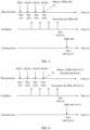
- Example 1-1 For example, the channel information is periodically fed back, and the current channel information is the PMI corresponding to the moment at which the CSI-RS is latest effectively measured.
- the terminal device receives the configuration information sent by the network device, where the configuration information is used to configure the feedback mode of the channel information, the CSI-RS measurement resource, and the channel information feedback resource.
- a feedback periodicity of the channel information is N slots.
- the configuration information is further used to configure the time offset T. T is a period of time in which the moment at which the channel information is fed back is used as a start point.
- the terminal device measures the CSI-RS in a slot (4N), to obtain a channel matrix H(4N) corresponding to the slot (4N), and obtains a PMI (4N) corresponding to the slot (4N) based on the channel matrix H(4N).
- the terminal device feeds back the PMI (4N) in a slot (4N+X).
- the network device After receiving the PMI (4N), the network device sends downlink data in a slot (4N+X+T) by using a precoder determined based on the PMI (4N).
- X is a time interval between the moment at which the CSI-RS is latest effectively measured and the moment at which the corresponding channel information is fed back.
- the terminal device measures the CSI-RS in a slot (4N), to obtain a channel matrix H(4N) corresponding to the slot (4N).
- the terminal device obtains, through prediction based on the channel matrix H(4N), a historical channel matrix H(N) to a historical channel matrix H(3N), and the time offset T, a channel matrix H(4N+X+T) corresponding to a slot (4N+X+T).
- the terminal device obtains a predicted PMI (4N+X+T) based on the channel matrix H(4N+X+T).
- the terminal device feeds back the predicted PMI (4N+X+T) in a slot (4N+X).
- the network device After receiving the predicted PMI (4N+X+T), the network device sends downlink data in the slot (4N+X+T) by using a precoder determined based on the PMI (4N+X+T).
- the time offset T may be any one of the following three offsets: 1.
- the time offset T is a period of time in which a moment t2 at which the terminal device receives trigger signaling is used as a start point. In an implementation, the time offset T may be greater than or equal to a time interval between the moment t2 and the moment at which the channel information is fed back.
- the trigger signaling is signaling used to trigger CSI-RS measurement, and the trigger signaling may be DCI signaling.
- the time offset T is a period of time in which the moment at which the channel information is fed back is used as a start point. 3.
- the time offset T is a period of time in which the moment at which the CSI-RS is latest effectively measured is used as a start point, and the time offset T is greater than or equal to a time interval between the moment at which the channel information is fed back and the moment, at which the CSI is latest effectively measured, corresponding to the moment at which the channel information is fed back.
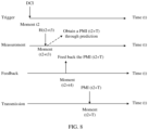
- Example 1-2 For example, the channel information is aperiodically fed back, and the current channel information is the PMI corresponding to the moment at which the CSI-RS is latest effectively measured.
- the terminal device receives, at a moment t2, DCI signaling used to trigger CSI-RS measurement.
- the DCI signaling carries the configuration information, and the configuration information is used to configure the feedback mode of the channel information, the CSI-RS measurement resource, and the channel information feedback resource.
- the moment at which the CSI-RS is latest effectively measured is t2+t3
- the moment at which the channel information is fed back is t2+t4.
- the configuration information is further used to configure the time offset T.
- T is a period of time in which the moment t2 corresponding to DCI for triggering CSI-RS measurement is used as a start point.
- the terminal device measures the CSI-RS at the moment t2+t3, to obtain a channel matrix H(t2+t3) corresponding to the moment t2+t3, and obtains a PMI (t2+t3) corresponding to the moment t2+t3 based on the channel matrix H(t2+t3).
- the terminal device feeds back the PMI (t2+t3) at the moment (t2+t4).
- the network device After receiving the PMI (t2+t3), the network device sends downlink data at a moment (t2+T) by using a precoder determined based on the PMI (t2+t3).
- the terminal device measures the CSI-RS at the moment t2+t3, to obtain a channel matrix H(t2+t3) corresponding to the moment t2+t3, and obtains a predicted PMI (t2+T) based on the channel matrix H(t2+t3), a historically measured channel matrix, and the time offset T.
- the terminal device feeds back the predicted PMI (t2+T) at the moment (t2+t4).
- the network device After receiving the predicted PMI (t2+T), the network device sends downlink data at a moment (t2+T) by using a precoder determined based on the predicted PMI (t2+T).
- T may use the CSI measurement moment t2+t3 or the CSI feedback moment t2+t4 as a start point. Principles are consistent, and therefore descriptions are not repeatedly provided.
- a time-varying characteristic of a channel is represented by a Doppler frequency, and varying of the Doppler frequency is usually more slowly than that of the channel in time domain, so that channels have correlation in time domain. Because the channels have correlation in time domain, a future channel may be obtained through prediction based on time domain correlation of the channel matrix H.
- a channel matrix [H(1), H(2), ..., H(O+L)] may be obtained.
- the following uses one angle-delay pair as an example, and a principle of another angle-delay pair is the same as that of this angle-delay pair.
- a corresponding angle-delay domain channel coefficient C [c(1), c(2), ..., c(O+L)] is obtained, where C may be a 1 ⁇ (O+L) vector, c(1), c(2), ..., c(O+L) are elements of C.
- measurement channels (or sampling channels) of the angle-delay pair at (O+L) moments are c(1), c(2), ..., c(O+L).
- the equation may be simply understood as that any (L+1) th channel may be represented as a weighted sum of the weighting coefficients ⁇ a 1 , ..., a L ⁇ of the first L channels.
- a start position of each row may be independent, provided that spacings between channel samples in the rows are aligned, that is, time intervals are the same.
- a start position of the first row may be c(1), for example, the first row may be c(1), c(2), and c(3);
- a start position of the second row may be c(4), for example, the second row may be c(4), c(5), and c(6);
- a start position of the third row may be c(2), for example, the third row may be c(2), c(3), and c(4).
- X 1 is c 1 ⁇ c L ⁇ ⁇ ⁇ ⁇ c O ⁇ c O + L ⁇ 1
- Y 1 is c L + 1 ⁇ c O + L
- a is a 1 ⁇ a L .
- the weighting coefficients ⁇ a 1 , ..., a L ⁇ can be more robust by using the O equations.
- the channel sampling in the foregoing formula may also be a channel matrix H, that is, c(n) in the foregoing formula may be replaced with H(n).
- H space-frequency matrices obtained through measurement at (O+L) moments are H(1), H(2), ..., H(O+L).
- H 1 ⁇ H L ⁇ ⁇ ⁇ H O ⁇ H O + L ⁇ 1 a 1 ⁇ a L H L + 1 ⁇ H O + L , where ⁇ a 1 , ..., a L ⁇ are the L weighting coefficients, and H(1) to H(O+L) are all known measurement channels (or known sampling channels, namely, space-frequency matrices obtained through channel measurement).
- X 2 is H 1 ⁇ H L ⁇ ⁇ ⁇ H O ⁇ H O + L ⁇ 1
- Y 2 is H L + 1 ⁇ H O + L
- a is a 1 ⁇ a L .
- a may be a least squares solution of the foregoing equation. It should be understood that the foregoing formula is merely an example for description, and this embodiment of this application is not limited thereto. Any variation of the formula falls within the protection scope of this embodiment of this application. It should be further understood that c(n) and H(n) are used as examples for description. This embodiment of this application is not limited thereto. Any manner in which a channel can be represented falls within the protection scope of this embodiment of this application.
- a corresponding channel matrix H(O+L+1) may be obtained by using c(O+L+1).
- Manner 2 When the feedback mode configured by using the configuration information is the second mode, the terminal device determines a plurality of pieces of predicted channel information based on one or more of information of the time offset T, window duration, or a time domain feedback granularity, where the window duration is a time interval between moments of the first piece of channel information and the last piece of channel information in the plurality of pieces of predicted channel information, and the time domain feedback granularity is a time interval between moments at which two adjacent pieces of channel information are fed back; and the terminal device feeds back one or more pieces of predicted channel information to the network device.
- the terminal device may feed back the one or more pieces of predicted channel information, so that the network device can use the predicted channel information to perform matching on a time-varying channel within the window duration. This further improves system performance.
- the configuration information is further used to configure one or more of the time offset T, the window duration, or the time domain feedback granularity.
- Information that is in the configuration information and that is used to configure the feedback mode and information that is in the configuration information and that is used to configure the time offset T, the window duration, or the time domain feedback granularity may be sent to the terminal device in same signaling, or may be sent to the terminal device in different signaling.
- the time offset T, the window duration, or the time domain feedback granularity may be specified in a protocol in advance.
- the terminal device determines the plurality of pieces of predicted channel information based on the time offset T and the window duration, and then feeds back at least two pieces of predicted channel information from the plurality of pieces of predicted channel information based on the feedback granularity.
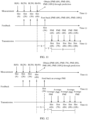
- Example 2-1 For example, the channel information is periodically fed back.
- the terminal device receives the configuration information sent by the network device, where the configuration information is used to configure the feedback mode of the channel information to be the second mode, and configure the CSI-RS measurement resource, the channel information feedback resource, the time offset T, the window duration D, and the time domain feedback granularity M.
- T is a period of time in which the moment at which the channel information is fed back is used as a start point.
- the terminal device measures the CSI-RS in a slot (4N), to obtain a channel matrix H(4N).
- the terminal device predicts a channel matrix H(4+X+T), a channel matrix H(4N+X+T+1), ..., a channel matrix H(4N+X+T+N) based on channel matrices H(N) to H(4N).
- X is a time interval between the moment at which the channel information is fed back and the moment at which the CSI-RS is latest effectively measured.
- X is N slots
- the time offset T is N slots
- the time domain feedback granularity M is N slots
- the window duration D is 4N slots.
- the terminal device obtains a channel matrix H(6N) to a channel matrix H(10N) through prediction based on the foregoing solution.
- the terminal device obtains a predicted PMI (6N) to a predicted PMI (10N) based on the predicted channel matrix H(6N) to the predicted channel matrix H(10N). Because the time domain feedback granularity M is N slots, the terminal device feeds back the predicted PMI (6N) to the predicted PMI (10N) in a slot (4N+X).
- the network device After receiving the predicted PMI (6N) to the predicted PMI (10N), the network device sends downlink data in a corresponding slot by using a precoder determined based on a corresponding PMI.
- Example 2-2 For example, M is 2N slots. As shown in FIG. 10 , the terminal device obtains a PMI (6N) to a PMI (10N) through prediction in the manner of example 2-1. The time domain feedback granularity M is 2N slots. Therefore, the terminal device feeds back the predicted PMI (6N), the predicted PMI (8N), and the predicted PMI (10N) in a slot (4N+X).
- the network device After receiving the predicted PMI (6N), the predicted PMI (8N), and the predicted PMI (10N), the network device sends downlink data in a slot (6N) and a slot (7N) by using a precoder obtained based on the PMI (6N), sends downlink data in a slot (8N) and a slot (9N) by using a precoder obtained based on the PMI (8N), and sends downlink data in a slot (10N) by using a precoder obtained based on the PMI (10N).
- the network side device may perform interpolation on the PMI at an intermediate moment based on the PMI (6N), the PMI (8N), and the PMI (10N), to obtain the PMI (7N) and the PMI (9N). This is not limited herein.
- the terminal device determines the plurality of pieces of predicted channel information based on the time offset T, the window duration, and the time domain feedback granularity, and feeds back the plurality of pieces of predicted channel information. Based on this possible implementation, processing resources are saved.
- Example 2-3 X is N slots, the time offset T is N slots, the time domain feedback granularity M is 2N slots, and the window duration D is 4N slots.
- X is a time interval between the moment at which the channel information is fed back and the moment at which the CSI-RS is latest effectively measured.
- T is a period of time in which the moment at which the channel information is fed back is used as a start point.
- the terminal device predicts a channel matrix H(4N+X+T), a channel matrix H(4N+X+T+2), ..., a channel matrix H(4N+X+T+N) in a slot (4N).
- the terminal device predicts a channel matrix H(6N), a channel matrix H(8N), and a channel matrix H(10N) in the slot (4N).
- the terminal device obtains a predicted PMI (6N), a predicted PMI (8N), and a predicted PMI (10N) based on the predicted channel matrix H(6N), the predicted channel matrix H(8N), and the predicted channel matrix H(10N).
- the terminal device feeds back the predicted PMI (6N), the predicted PMI (8N), and the predicted PMI (10N) in a slot (4N+X).
- the network device After receiving the predicted PMI (6N), the predicted PMI (8N), and the predicted PMI (10N), the network device sends downlink data in a slot (6N) and a slot (7N) by using a precoder obtained based on the PMI (6N), sends downlink data in a slot (8N) and a slot (9N) by using a precoder obtained based on the PMI (8N), and sends downlink data in a slot (10N) by using a precoder obtained based on the PMI (10N).
- the network side device may perform interpolation on the PMI at an intermediate moment based on the PMI (6N), the PMI (8N), and the PMI (10N), to obtain the PMI (7N) and the PMI (9N). This is not limited herein.
- the terminal device determines the plurality of pieces of predicted channel information based on the time offset T and the window duration D, and selects any one or more pieces of the plurality of pieces of predicted channel information for feedback, or feeds back an average value of the plurality of pieces of predicted channel information. Based on this possible implementation, transmission resources are saved.
- Example 2-4 As shown in FIG. 12 , the terminal device obtains a PMI (6N) to a PMI (10N) in a slot (4N) through prediction in the manner of example 2-1. The terminal device determines an average PMI of the PMI (6N) to the PMI (10N). The terminal device feeds back the average PMI in a slot (4N+X). After receiving the average PMI, the network device sends downlink data within the window duration D in which the time offset T is used as start time by using a precoder determined based on the average PMI. Alternatively, the terminal device feeds back any one or more of the PMI (6N) to the PMI (10N) in the slot (4N+X). In FIG. 12 , for example, an average PMI is fed back.
- the terminal device feeds back, to the network device, channel information obtained through processing of a codebook, where the codebook is a codebook based on a time domain dimension, and the channel information obtained through processing or projection of the codebook represents the one or more pieces of predicted channel information.
- the network device decompresses or performs back projection on the channel information by using the codebook, to obtain the one or more pieces of predicted channel information.
- the codebook may be a Doppler codebook. Based on this possible implementation, transmission resources are saved.
- Example 2-5 As shown in FIG. 13 , after the terminal device obtains a predicted PMI (6N) to a predicted PMI (10N) in a slot (4N) in the manner of example 2-1, the terminal device compresses the PMI (6N) to the PMI (10N) by using a codebook, to obtain compressed channel information P_DP. The terminal device feeds back P_DP to the network device. After receiving P_DP, the network device decompresses P_DP by using the codebook, to obtain the PMI (6N) to the PMI (10N). After receiving the predicted PMI (6N) to the predicted PMI (10N), the network device sends downlink data in a corresponding slot by using a precoder determined based on a corresponding PMI.
- channels H(6N) to H(10N) or a PMI (6N) to a PMI (10N) at a plurality of moments may be represented by using a Doppler codebook.
- H(6N) to H(10N) or the PMI (6N) to the PMI (10N) are represented as a sum of sum coefficients of L 1 space domain vectors, K frequency domain vectors, and N_ slot time domain vectors, where L 1 , K, and N_ slot may be configured by a base station.
- a s,f,t is a sum coefficient, and is a complex number.
- S, F, and R are a space domain base vector, a frequency domain base vector, and a time domain base vector respectively, and lengths thereof are represented as N 1 , N sb , and N slot respectively.
- Q may be equal to 1.
- Q represents that no oversampling is performed, that is, corresponds to the DFT vector.
- the space domain base vector is special. Usually, an antenna panel is a square array, and antenna array elements or equivalent ports (ports) are distributed in two dimensions.
- Q H and Q v are oversampling ratios
- G H and G v are vector lengths
- a value range of g is 0 to Q H G H -1
- a value range of m is 0 to Q v G v -1.
- Q v and/or Q v may be 1.
- Example 1-1 Example 1-2, and Example 2-1 to Example 2-5, that the predicted channel information is a predicted PMI is used as an example.
- the predicted channel information is a predicted channel coefficient
- an implementation principle is the same as that of this example, and details are not described herein again.
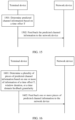
- FIG. 14 is a schematic flowchart of a channel information feedback method according to an embodiment of this application.
- the channel information feedback method includes the following step 1401 to step 1403.
- the method shown in FIG. 14 may be performed by a network device and a terminal device.
- the method shown in FIG. 14 may be performed by a chip in the network device and a chip in the terminal device.
- FIG. 14 an example in which the network device and the terminal device are execution bodies is used for description.
- the network device sends configuration information to the terminal device.
- the configuration information is used to configure a first parameter.
- the first parameter When the first parameter configured by using the configuration information meets a first condition, the first parameter is used to indicate the terminal device to feed back current channel information; or when the first parameter configured by using the configuration information meets a second condition, the first parameter is used to indicate the terminal device to feed back predicted channel information.
- the first parameter, the first condition, and the second condition refer to the descriptions in the foregoing method embodiment. Details are not described herein again.
- the terminal device feeds back the current channel information to the network device when the first parameter configured by using the configuration information meets the first condition.
- the terminal device feeds back the predicted channel information to the network device when the first parameter configured by using the configuration information meets the second condition.
- the network device receives the current channel information fed back by the terminal device when the first parameter configured by using the configuration information meets the first condition.
- the network device receives the predicted channel information fed back by the terminal device when the first parameter configured by using the configuration information meets the second condition.
- channel information feedback requirements in different scenarios can be met, feedback overheads can be reduced, and system performance can be improved.
- FIG. 15 is a schematic flowchart of a channel information feedback method according to an embodiment of this application.
- the channel information feedback method includes the following step 1501 and step 1502.
- the method shown in FIG. 15 may be performed by a terminal device.
- the method shown in FIG. 15 may be performed by a chip in the terminal device.
- FIG. 15 an example in which the terminal device is an execution body is used for description.
- the terminal device determines predicted channel information based on a time offset T.
- a network device may further send configuration information to the terminal device, where the configuration information is used to configure the time offset T.
- the terminal device may further receive the configuration information.
- the time offset T may be specified in a protocol in advance. For other related descriptions of the time offset T, refer to the descriptions in the foregoing embodiments. Details are not described herein again.
- the terminal device feeds back the predicted channel information to the network device.
- the terminal device after determining the predicted channel information, the terminal device feeds back the predicted channel information to the network device.
- the network device may receive the predicted channel information fed back by the terminal device.
- step 1501 and step 1502 refer to the descriptions in the first specific implementation in which the terminal device feeds back the predicted channel information to the network device in the foregoing method embodiments. Details are not described herein again.
- the terminal device may report the predicted channel information for which the time offset T is compensated, to match a channel during actual transmission. This improves system performance.
- FIG. 16 is a schematic flowchart of a channel information feedback method according to an embodiment of this application.
- the channel information feedback method includes the following step 1601 and step 1602.
- the method shown in FIG. 16 may be performed by a terminal device.
- the method shown in FIG. 16 may be performed by a chip in the terminal device.
- FIG. 16 an example in which the terminal device is an execution body is used for description.
- the terminal device determines a plurality of pieces of predicted channel information based on one or more of information of a time offset T, window duration, or a time domain feedback granularity.
- a network device may further send configuration information to the terminal device, where the configuration information is used to configure one or more of the time offset T, the window duration, or the time domain feedback granularity.
- the terminal device may further receive the configuration information.
- the time offset T, the window duration, or the time domain feedback granularity may be specified in a protocol in advance. For other related descriptions of the time offset T, the window duration, or the time domain feedback granularity, refer to the descriptions in the foregoing embodiments. Details are not described herein again.
- the terminal device feeds back one or more pieces of predicted channel information to the network device.
- a manner in which the terminal device feeds back the one or more pieces of predicted channel information to the network device is specifically: The terminal device feeds back channel information obtained through processing of a codebook to the network device, where the codebook is a codebook based on a time domain dimension, and the channel information obtained through processing of the codebook represents the one or more pieces of predicted channel information.
- step 1601 and step 1602 refer to the descriptions in the second specific implementation in which the terminal device feeds back the predicted channel information to the network device in the foregoing method embodiments. Details are not described herein again.
- the terminal device may feed back the one or more pieces of predicted channel information, so that the network device can use the predicted channel information to perform matching on a time-varying channel within the window duration. This further improves system performance.
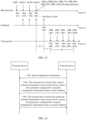
- FIG. 17 is a schematic diagram of a structure of a communication apparatus according to an embodiment of this application.
- the communication apparatus shown in FIG. 17 may be configured to perform some or all functions of the terminal device in the method embodiment described in FIG. 4 .
- the apparatus may be a terminal device, an apparatus in the terminal device, or an apparatus that can be used together with the terminal device.
- the communication apparatus may alternatively be a chip system.
- the communication apparatus shown in FIG. 17 may include a communication unit 1701 and a processing unit 1702.
- the communication unit may alternatively be referred to as a transceiver unit, or the communication unit includes a receiving unit and a sending unit.
- the processing unit 1702 is configured to process data.
- the communication unit 1701 is configured to receive configuration information sent by a network device, where the configuration information is used to configure a feedback mode of channel information; and the communication unit 1701 is further configured to feed back current channel information to the network device when the feedback mode configured by using the configuration information is a first mode; or the communication unit 1701 is further configured to feed back predicted channel information to the network device when the feedback mode configured by using the configuration information is a second mode.
- the current channel information is a current precoding matrix indicator PMI
- the predicted channel information is a predicted channel coefficient
- the configuration information includes a first parameter; and when the first parameter meets a first condition, the configuration information is used to configure the first mode; or when the first parameter meets a second condition, the configuration information is used to configure the second mode, and the first condition is different from the second condition.
- a manner in which the communication unit 1701 feeds back the predicted channel information to the network device is specifically: determining the predicted channel information based on a time offset T when the feedback mode configured by using the configuration information is the second mode; and feeding back the predicted channel information to the network device.
- the configuration information is further used to configure the time offset T.
- a manner in which the communication unit 1701 feeds back the predicted channel information to the network device is specifically: when the feedback mode configured by using the configuration information is the second mode, determining a plurality of pieces of predicted channel information based on one or more of information of a time offset T, window duration, or a time domain feedback granularity, where the window duration is a time interval between moments at which the first piece of channel information and the last piece of channel information are predicted, and the time domain feedback granularity is a time interval between moments at which two adjacent pieces of channel information are fed back; and feeding back one or more pieces of predicted channel information to the network device.
- a manner in which the communication unit 1701 feeds back the one or more pieces of predicted channel information to the network device is specifically: feeding back channel information obtained through processing of a codebook to the network device, where the codebook is a codebook based on a time domain dimension, and the channel information obtained through processing of the codebook represents the one or more pieces of predicted channel information.
- the configuration information is further used to configure one or more of the time offset T, the window duration, or the time domain feedback granularity.
- FIG. 17 is a schematic diagram of a structure of a communication apparatus according to an embodiment of this application.
- the communication apparatus shown in FIG. 17 may be configured to perform some or all functions of the network device in the method embodiment described in FIG. 4 .
- the apparatus may be a network device, an apparatus in the network device, or an apparatus that can be used together with the network device.
- the communication apparatus may alternatively be a chip system.
- the communication apparatus shown in FIG. 17 may include a communication unit 1701 and a processing unit 1702.
- the communication unit may alternatively be referred to as a transceiver unit, or the communication unit includes a receiving unit and a sending unit.
- the processing unit 1702 is configured to process data.
- the communication unit 1701 is configured to send configuration information to a terminal device, where the configuration information is used to configure a feedback mode of channel information; and when the feedback mode configured by using the configuration information is a first mode, the feedback mode is used to indicate the terminal device to feed back current channel information; or when the feedback mode configured by using the configuration information is a second mode, the feedback mode is used to indicate the terminal device to feed back predicted channel information.
- the communication unit 1701 is configured to receive the current channel information fed back by the terminal device when the feedback mode configured by using the configuration information is the first mode; and is further configured to receive the predicted channel information fed back by the terminal device when the feedback mode configured by using the configuration information is the second mode.
- the current channel information is a current precoding matrix indicator PMI
- the predicted channel information is a predicted channel coefficient
- the configuration information includes a first parameter; and when the first parameter meets a first condition, the configuration information is used to configure the first mode; or when the first parameter meets a second condition, the configuration information is used to configure the second mode, and the first condition is different from the second condition.
- the configuration information is further used to configure a time offset T.
- the configuration information is further used to configure one or more of a time offset T, window duration, or a time domain feedback granularity, where the window duration is a time interval between moments at which the first piece of channel information and the last piece of channel information are predicted by the terminal device, and the time domain feedback granularity is a time interval between moments at which two adjacent pieces of channel information are fed back by the terminal device.
- a manner in which the communication unit 1701 receives the predicted channel information fed back by the terminal device is specifically: further receiving one or more pieces of predicted channel information fed back by the terminal device.
- a manner in which the communication unit 1701 receives the one or more pieces of predicted channel information fed back by the terminal device is specifically: receiving channel information, obtained through processing of a codebook, that is fed back by the terminal device, where the codebook is a codebook based on a time domain dimension, and the channel information obtained through processing of the codebook represents the one or more pieces of predicted channel information.
- FIG. 17 is a schematic diagram of a structure of a communication apparatus according to an embodiment of this application.
- the communication apparatus shown in FIG. 17 may be configured to perform some or all functions of the terminal device in the method embodiment described in FIG. 14 .
- the apparatus may be a terminal device, an apparatus in the terminal device, or an apparatus that can be used together with the terminal device.
- the communication apparatus may alternatively be a chip system.
- the communication apparatus shown in FIG. 17 may include a communication unit 1701 and a processing unit 1702.
- the communication unit may alternatively be referred to as a transceiver unit, or the communication unit includes a receiving unit and a sending unit.
- the processing unit 1702 is configured to process data.
- the communication unit 1701 is configured to receive configuration information sent by a network device, where the configuration information is used to configure a first parameter; and the communication unit 1701 is further configured to feed back current channel information to the network device when the first parameter configured by using the configuration information meets a first condition; or the communication unit 1701 is further configured to feed back predicted channel information to the network device when the first parameter configured by using the configuration information meets a second condition.
- the current channel information is a current precoding matrix indicator PMI
- the predicted channel information is a predicted channel coefficient
- a manner in which the communication unit 1701 feeds back the predicted channel information to the network device is specifically: when the first parameter configured by using the configuration information meets the second condition, determining the predicted channel information based on a time offset T; and feeding back the predicted channel information to the network device.
- the configuration information is further used to configure the time offset T.
- a manner in which the communication unit 1701 feeds back the predicted channel information to the network device is specifically: when the first parameter configured by using the configuration information meets the second condition, determining a plurality of pieces of predicted channel information based on one or more of information of a time offset T, window duration, or a time domain feedback granularity, where the window duration is a time interval between moments at which the first piece of channel information and the last piece of channel information are predicted, and the time domain feedback granularity is a time interval between moments at which two adjacent pieces of channel information are fed back; and feeding back one or more pieces of predicted channel information to the network device.
- a manner in which the communication unit 1701 feeds back the one or more pieces of predicted channel information to the network device is specifically: feeding back channel information obtained through processing of a codebook to the network device, where the codebook is a codebook based on a time domain dimension, and the channel information obtained through processing of the codebook represents the one or more pieces of predicted channel information.
- the configuration information is further used to configure one or more of the time offset T, the window duration, or the time domain feedback granularity.
- FIG. 17 is a schematic diagram of a structure of a communication apparatus according to an embodiment of this application.
- the communication apparatus shown in FIG. 17 may be configured to perform some or all functions of the network device in the method embodiment described in FIG. 14 .
- the apparatus may be a network device, an apparatus in the network device, or an apparatus that can be used together with the network device.
- the communication apparatus may alternatively be a chip system.
- the communication apparatus shown in FIG. 17 may include a communication unit 1701 and a processing unit 1702.
- the communication unit may alternatively be referred to as a transceiver unit, or the communication unit includes a receiving unit and a sending unit.
- the processing unit 1702 is configured to process data.
- the communication unit 1701 is configured to send configuration information to a terminal device, where the configuration information is used to configure a first parameter; and when the first parameter configured by using the configuration information meets a first condition, the first parameter is used to indicate the terminal device to feed back current channel information; or when the first parameter configured by using the configuration information meets a second condition, the first parameter is used to indicate the terminal device to feed back predicted channel information.
- the communication unit 1701 is configured to receive the current channel information fed back by the terminal device when the first parameter configured by using the configuration information meets the first condition; and is further configured to receive the predicted channel information fed back by the terminal device when the first parameter configured by using the configuration information meets the first condition.
- the current channel information is a current precoding matrix indicator PMI
- the predicted channel information is a predicted channel coefficient
- the configuration information is further used to configure a time offset T.
- the configuration information is further used to configure one or more of a time offset T, window duration, or a time domain feedback granularity, where the window duration is a time interval between moments at which the first piece of channel information and the last piece of channel information are predicted by the terminal device, and the time domain feedback granularity is a time interval between moments at which two adjacent pieces of channel information are fed back by the terminal device.
- a manner in which the communication unit 1701 receives the predicted channel information fed back by the terminal device is specifically: receiving one or more pieces of predicted channel information fed back by the terminal device.
- a manner in which the communication unit 1701 receives the one or more pieces of predicted channel information fed back by the terminal device is specifically: receiving channel information, obtained through processing of a codebook, that is fed back by the terminal device, where the codebook is a codebook based on a time domain dimension, and the channel information obtained through processing of the codebook represents the one or more pieces of predicted channel information.
- FIG. 17 is a schematic diagram of a structure of a communication apparatus according to an embodiment of this application.
- the communication apparatus shown in FIG. 17 may be configured to perform some or all functions of the terminal device in the method embodiment described in FIG. 15 .
- the apparatus may be a terminal device, an apparatus in the terminal device, or an apparatus that can be used together with the terminal device.
- the communication apparatus may alternatively be a chip system.
- the communication apparatus shown in FIG. 17 may include a communication unit 1701 and a processing unit 1702.
- the communication unit may alternatively be referred to as a transceiver unit, or the communication unit includes a receiving unit and a sending unit.
- the processing unit 1702 is configured to process data.
- the processing unit 1702 is configured to determine predicted channel information based on a time offset T; and the communication unit 1701 is configured to feed back the predicted channel information to a network device.
- the communication unit 1701 is further configured to receive configuration information sent by the network device, where the configuration information is used to configure the time offset T.
- the predicted channel information is a predicted PMI or a predicted channel coefficient.
- FIG. 17 is a schematic diagram of a structure of a communication apparatus according to an embodiment of this application.
- the communication apparatus shown in FIG. 17 may be configured to perform some or all functions of the network device in the method embodiment described in FIG. 15 .
- the apparatus may be a network device, an apparatus in the network device, or an apparatus that can be used together with the network device.
- the communication apparatus may alternatively be a chip system.
- the communication apparatus shown in FIG. 17 may include a communication unit 1701 and a processing unit 1702.
- the communication unit may alternatively be referred to as a transceiver unit, or the communication unit includes a receiving unit and a sending unit.
- the processing unit 1702 is configured to process data.
- the communication unit 1701 is configured to receive predicted channel information fed back by a terminal device.
- the communication unit 1701 is further configured to send configuration information to the terminal device, where the configuration information is used to configure a time offset T.
- the predicted channel information is a predicted PMI or a predicted channel coefficient.
- FIG. 17 is a schematic diagram of a structure of a communication apparatus according to an embodiment of this application.
- the communication apparatus shown in FIG. 17 may be configured to perform some or all functions of the terminal device in the method embodiment described in FIG. 16 .
- the apparatus may be a terminal device, an apparatus in the terminal device, or an apparatus that can be used together with the terminal device.
- the communication apparatus may alternatively be a chip system.
- the communication apparatus shown in FIG. 17 may include a communication unit 1701 and a processing unit 1702.
- the communication unit may alternatively be referred to as a transceiver unit, or the communication unit includes a receiving unit and a sending unit.
- the processing unit 1702 is configured to process data.
- the processing unit 1702 is configured to determine a plurality of pieces of predicted channel information based on one or more pieces of information of a time offset T, window duration, or a time domain feedback granularity; and the communication unit 1701 is configured to feed back one or more pieces of predicted channel information to a network device.
- the communication unit 1701 is further configured to receive configuration information sent by the network device, where the configuration information is used to configure one or more of the time offset T, the window duration, or the time domain feedback granularity.
- a manner in which the communication unit 1701 feeds back the one or more pieces of predicted channel information to the network device is specifically: feeding back channel information obtained through processing of a codebook to the network device, where the codebook is a codebook based on a time domain dimension, and the channel information obtained through processing of the codebook represents the one or more pieces of predicted channel information.
- the predicted channel information is a predicted PMI or a predicted channel coefficient.
- FIG. 17 is a schematic diagram of a structure of a communication apparatus according to an embodiment of this application.
- the communication apparatus shown in FIG. 17 may be configured to perform some or all functions of the network device in the method embodiment described in FIG. 16 .
- the apparatus may be a network device, an apparatus in the network device, or an apparatus that can be used together with the network device.
- the communication apparatus may alternatively be a chip system.
- the communication apparatus shown in FIG. 17 may include a communication unit 1701 and a processing unit 1702.
- the communication unit may alternatively be referred to as a transceiver unit, or the communication unit includes a receiving unit and a sending unit.
- the processing unit 1702 is configured to process data.
- the communication unit 1701 is configured to receive one or more pieces of predicted channel information fed back by a terminal device.
- the communication unit 1701 is further configured to send configuration information to the terminal device, where the configuration information is used to configure one or more of a time offset T, window duration, or a time domain feedback granularity.
- a manner in which the communication unit 1701 receives the one or more pieces of predicted channel information fed back by the terminal device is specifically: receiving channel information, obtained through processing of a codebook, that is fed back by the terminal device, where the codebook is a codebook based on a time domain dimension, and the channel information obtained through processing of the codebook represents the one or more pieces of predicted channel information.
- the predicted channel information is a predicted PMI or a predicted channel coefficient.
- FIG. 18a shows a communication apparatus 180 according to an embodiment of this application.
- the communication apparatus 180 is configured to implement functions of the terminal device in the foregoing method embodiments.
- the apparatus may be a terminal device or an apparatus used in the terminal device.
- the apparatus used in the terminal device may be a chip system or a chip in the terminal device.
- the chip system may include a chip, or may include a chip and another discrete component.
- the communication apparatus 180 is configured to implement functions of the network device in the foregoing method embodiments.
- the apparatus may be a network device or an apparatus used in the network device.
- the apparatus used in the network device may be a chip system or a chip in the network device.
- the chip system may include a chip, or may include a chip and another discrete component.
- the communication apparatus 180 includes at least one processor 1820, configured to implement a data processing function of the terminal device or the network device in the method embodiments of this application.
- the processor 1820 is configured to perform a processing operation of the terminal device in the embodiment corresponding to FIG. 4 , or is configured to perform a processing operation of the terminal device in the embodiment corresponding to FIG. 14 , or is configured to perform step 1501 in FIG. 15 , or is configured to perform step 1601 in FIG. 16 .
- the processor 1820 is configured to perform a processing operation of the network device in the embodiment corresponding to FIG. 4 , FIG. 14 , FIG. 15, or FIG. 16 .
- the apparatus 180 may further include a communication interface 1810, configured to implement receiving and sending operations of the terminal device or the network device in the method embodiments of this application.
- the communication interface 1810 is configured to perform the step of receiving configuration information in FIG. 4 , and step 402 and step 403, or is configured to perform the step of receiving configuration information in FIG. 14 , and step 1402 and step 1403, or is configured to perform step 1502 in FIG. 15 , or is configured to perform step 1602 in FIG. 16 .
- the communication interface 1810 is configured to: perform step 401 in FIG. 4 , and receive current channel information or predicted channel information.
- the communication interface 1810 is configured to: perform step 1401 in FIG. 14 , and receive current channel information or predicted channel information.
- the communication interface 1810 is configured to perform the step of receiving predicted channel information in FIG. 15 .
- the communication interface 1810 is configured to perform the step of receiving one or more pieces of predicted channel information in FIG. 16 .
- the communication interface may be a transceiver, a circuit, a bus, a module, or a communication interface of another type, and is configured to communicate with another device through a transmission medium.
- the communication interface 1810 is used by an apparatus in the apparatus 180 to communicate with another device.
- the processor 1820 receives and sends data through the communication interface 1810, and is configured to implement the method in the foregoing method embodiments.
- the apparatus 180 may further include at least one memory 1830, configured to store program instructions and/or data.
- the memory 1830 is coupled to the processor 1820.
- the coupling in this embodiment of this application may be an indirect coupling or a communication connection between apparatuses, units, or modules in an electrical form, a mechanical form, or another form, and is used for information exchange between the apparatuses, the units, or the modules.
- the processor 1820 may cooperate with the memory 1830.
- the processor 1820 may execute the program instructions stored in the memory 1830. At least one of the at least one memory may be included in the processor.
- a specific connection medium between the communication interface 1810, the processor 1820, and the memory 1830 is not limited.
- the memory 1830, the communication interface 1820, and the communication interface 1810 are connected through a bus 1840 in FIG. 18a .
- the bus is represented by using a bold line in FIG. 18a .
- a manner of connection between other components is merely an example for description, and is not limited thereto.
- the bus may be classified into an address bus, a data bus, a control bus, and the like. For ease of representation, only one bold line is used to represent the bus in FIG. 18a , but this does not mean that there is only one bus or only one type of bus.
- the communication interface 1810 may output or receive a baseband signal.
- the communication interface 1810 may output or receive a radio frequency signal.
- the processor may be a general-purpose processor, a digital signal processor, an application-specific integrated circuit, a field-programmable gate array or another programmable logic device, a discrete gate or a transistor logic device, or a discrete hardware component, and may implement or perform the methods, steps, and logical block diagrams disclosed in embodiments of this application.
- the general-purpose processor may be a microprocessor, any conventional processor, or the like.
- the steps of the method disclosed with reference to embodiments of this application may be directly performed by a hardware processor, or may be performed by using a combination of hardware in the processor and a software module.
- FIG. 18b is a schematic diagram of a structure of another terminal device 1800 according to an embodiment of this application.
- the terminal device may perform the operations performed by the terminal device in the foregoing method embodiments.
- FIG. 18b shows only main components of the terminal device.
- the terminal device 1800 includes a processor, a memory, a radio frequency circuit, an antenna, and an input/output apparatus.
- the processor is mainly configured to: process a communication protocol and communication data, control the entire terminal device, execute a software program, and process data of the software program, for example, configured to support the terminal device to perform the procedure described in FIG. 4 , FIG. 14 , FIG. 15, or FIG. 16 .
- the memory is mainly configured to store the software program and the data.
- the radio frequency circuit is mainly configured to: perform conversion between a baseband signal and a radio frequency signal, and process the radio frequency signal.
- the antenna is mainly configured to send and receive a radio frequency signal in a form of an electromagnetic wave.
- the terminal device 1800 may further include an input/output apparatus, for example, a touchscreen, a display screen, or a keyboard.
- the input/output apparatus is mainly configured to: receive data entered by a user, and output data to the user. It should be noted that some types of terminal devices may have no input/output apparatus.
- the processor may read a software program in a storage unit, explain and execute instructions of the software program, and process data of the software program.
- the processor performs baseband processing on the to-be-sent data, and then outputs a baseband signal to a radio frequency circuit.
- the radio frequency circuit performs radio frequency processing on the baseband signal, and then sends, through the antenna, a radio frequency signal in a form of an electromagnetic wave.
- the radio frequency circuit receives the radio frequency signal through the antenna, converts the radio frequency signal into a baseband signal, and outputs the baseband signal to the processor.
- the processor converts the baseband signal into data, and processes the data.
- FIG. 18b shows only one memory and only one processor.
- the memory may also be referred to as a storage medium, a storage device, or the like. This is not limited in embodiments of this application.
- the processor may include a baseband processor and a central processing unit (central processing unit, CPU).
- the baseband processor is mainly configured to process a communication protocol and communication data.
- the CPU is mainly configured to: control the entire terminal device, execute a software program, and process data of the software program.
- the processor may alternatively be a network processor (network processor, NP) or a combination of a CPU and an NP.
- the processor may further include a hardware chip.
- the hardware chip may be an application-specific integrated circuit (application-specific integrated circuit, ASIC), a programmable logic device (programmable logic device, PLD), or a combination thereof.
- the PLD may be a complex programmable logic device (complex programmable logic device, CPLD), a field-programmable gate array (field-programmable gate array, FPGA), a generic array logic (generic array logic, GAL), or any combination thereof.
- the memory may include a volatile memory (volatile memory), for example, a random access memory (random-access memory, RAM).
- the memory may alternatively include a non-volatile memory (non-volatile memory), for example, a flash memory (flash memory), a hard disk drive (hard disk drive, HDD), or a solid-state drive (solid-state drive, SSD).
- flash memory flash memory
- HDD hard disk drive
- SSD solid-state drive
- the memory may alternatively include a combination of the foregoing types of memories.
- the antenna and the radio frequency circuit that have receiving and sending functions may be considered as a communication unit 1801 of the terminal device 1800, and the processor that has a processing function may be considered as a processing unit 1802 of the terminal device 1800.
- the communication unit 1801 may also be referred to as a transceiver, a transceiver machine, a transceiver apparatus, a transceiver unit, or the like, and is configured to implement the receiving and sending functions.
- a component that is in the communication unit 1801 and that is configured to implement the receiving function may be considered as a receiving unit
- a component that is in the communication unit 1801 and that is configured to implement the sending function may be considered as a sending unit.
- the communication unit 1801 includes the receiving unit and the sending unit.
- the receiving unit may also be referred to as a receiver machine, a receiver, a receiver circuit, or the like
- the sending unit may be referred to as a transmitter machine, a transmitter, a transmit circuit, or the like.
- the communication unit 1801 and the processing unit 1802 may be integrated into one component, or may be separated as different components.
- the processor and the memory may be integrated into one component, or may be separated as different components.
- the communication unit 1801 may be configured to perform receiving and sending operations of the terminal device in the foregoing method embodiments.
- the processing unit 1802 may be configured to perform a data processing operation of the terminal device in the foregoing method embodiments.
- An embodiment of this application further provides a computer-readable storage medium.
- the computer-readable storage medium stores instructions. When run on a processor, the instructions are used to perform the method performed by the terminal device in the foregoing method embodiments.
- An embodiment of this application further provides a computer-readable storage medium.
- the computer-readable storage medium stores instructions. When run on a processor, the instructions are used to perform the method performed by the network device in the foregoing method embodiments.
- An embodiment of this application further provides a computer program product.
- the computer program product runs on a processor, the computer program product is used to perform the method performed by the terminal device in the foregoing method embodiments.
- An embodiment of this application further provides a computer program product.
- the computer program product runs on a processor, the computer program product is used to perform the method performed by the network device in the foregoing method embodiments.
- An embodiment of this application further provides a communication system.
- the communication system includes a terminal device and a network device.
- the terminal device is configured to perform the method performed by the terminal device in the foregoing method embodiments.
- the network device is configured to perform the method performed by the network device in the foregoing method embodiments.
Landscapes
- Engineering & Computer Science (AREA)
- Computer Networks & Wireless Communication (AREA)
- Signal Processing (AREA)
- Physics & Mathematics (AREA)
- Mathematical Physics (AREA)
- Power Engineering (AREA)
- Mobile Radio Communication Systems (AREA)
Claims (14)
- Procédé de rétroaction d'informations de canal, dans lequel le procédé comprend :la réception (401), par un dispositif terminal, d'informations de configuration envoyées par un dispositif de réseau, dans lequel les informations de configuration sont utilisées pour configurer un mode de rétroaction d'informations de canal ; etla rétroaction (402), par le dispositif terminal, des informations de canal actuel au dispositif de réseau lorsque le mode de rétroaction configuré à l'aide des informations de configuration est un premier mode ; oula rétroaction (403), par le dispositif terminal, des informations de canal prédites au dispositif de réseau lorsque le mode de rétroaction configuré à l'aide des informations de configuration est un second mode ; caractérisé en ce que les informations de canal actuelles sont un indicateur de matrice de précodage actuel, PMI, et que les informations de canal prédites sont un coefficient de canal prédit, dans lequel le coefficient de canal prédit est un coefficient de canal prédit dans le domaine angle-délai, C.
- Procédé selon la revendication 1, dans lequel les informations de configuration comprennent un premier paramètre ; etlorsque le premier paramètre remplit une première condition, les informations de configuration sont utilisées pour configurer le premier mode ; oulorsque le premier paramètre répond à une seconde condition, les informations de configuration sont utilisées pour configurer le second mode, et la première condition est différente de la seconde.
- Procédé selon la revendication 1 ou 2, dans lequel la rétroaction, par le dispositif terminal, des informations de canal prédites au dispositif de réseau lorsque le mode de rétroaction configuré à l'aide des informations de configuration est un second mode comprend :la détermination, par le dispositif terminal, des informations de canal prédites sur la base d'un décalage temporel T lorsque le mode de rétroaction configuré à l'aide des informations de configuration est le second mode ; etla rétroaction, par le dispositif terminal, des informations de canal prédites au dispositif de réseau.
- Procédé selon la revendication 3, dans lequel, lorsque le mode de rétroaction configuré à l'aide des informations de configuration est le second mode, les informations de configuration sont également utilisées pour configurer le décalage temporel T.
- Procédé selon la revendication 1 ou 2, dans lequel la rétroaction, par le dispositif terminal, des informations de canal prédites au dispositif de réseau lorsque le mode de rétroaction configuré à l'aide des informations de configuration est un second mode comprend :lorsque le mode de rétroaction configuré à l'aide des informations de configuration est le second mode, la détermination, par le dispositif terminal, d'une pluralité d'éléments d'informations de canal prédites sur la base d'une ou plusieurs informations d'un décalage temporel T, d'une durée de fenêtre ou d'une granularité de rétroaction dans le domaine temporel, dans lequel la durée de fenêtre est un intervalle de temps entre les moments du premier élément des informations de canal et le dernier éléments des informations de canal dans la pluralité d'éléments d'informations de canal prédites, et la granularité de rétroaction dans le domaine temporel est un intervalle de temps entre les moments auxquels deux éléments d'informations de canal adjacents dont la rétroaction est effectuée ; etla rétroaction, par le dispositif terminal, d'un ou plusieurs éléments d'informations prédites sur le dispositif réseau.
- Procédé selon la revendication 5, dans lequel la rétroaction, par le dispositif terminal, d'un ou plusieurs éléments d'informations de canal prédit au dispositif de réseau comprend :
la rétroaction, par le dispositif terminal au dispositif de réseau, des informations de canal obtenues par le traitement d'un livre de codes, dans lequel le livre de codes est un livre de codes basé sur une dimension de domaine temporel, et les informations sur le canal obtenues par le traitement du livre de codes représentent un ou plusieurs éléments d'informations de canal prédites. - Procédé selon la revendication 5 ou 6, dans lequel lorsque le mode de rétroaction est configuré à l'aide des informations de configuration est le second mode, les informations de configuration sont en outre utilisées pour configurer l'un parmi le décalage temporel T, la durée de la fenêtre ou la granularité de la rétroaction dans le domaine temporel.
- Procédé de rétroaction d'informations de canal, dans lequel le procédé comprend :l'envoi (401), par un dispositif de réseau, d'informations de configuration à un dispositif terminal, dans lequel les informations de configuration sont utilisées pour configurer un mode de rétroaction des informations de canal ; etlorsque le mode de rétroaction configuré à l'aide des informations de configuration est un premier mode, le mode de rétroaction est utilisé pour indiquer au dispositif terminal d'effectuer la rétroaction des informations de canal actuelles ; oulorsque le mode de rétroaction configuré à l'aide des informations de configuration est un second mode, le mode de rétroaction est utilisé pour indiquer au dispositif terminal d'effectuer la rétroaction des informations de canal prédites ; caractérisé en ce que les informations de canal actuelles sont un indicateur de matrice de précodage actuel, PMI, et les informations de canal prédites sont un coefficient de canal prédit, dans lequel le coefficient de canal prédit est un coefficient de canal prédit dans le domaine angle-délai, C.
- Procédé selon la revendication 8, comprenant en outrela réception (402) des informations de canal actuelles dont la rétroaction a été effectuée par le dispositif terminal au dispositif de réseau lorsque le mode de rétroaction configuré à l'aide des informations de configuration est le premier mode ; oula réception (403) des informations de canal prédites dont la rétroaction a été effectuée par le dispositif terminal au dispositif de réseau lorsque le mode de rétroaction configuré à l'aide des informations de configuration est le second mode.
- Procédé selon la revendication 8 ou 9, dans lequel les informations de configuration comprennent un premier paramètre ; etlorsque le premier paramètre remplit une première condition, les informations de configuration sont utilisées pour configurer le premier mode ; oulorsque le premier paramètre répond à une seconde condition, les informations de configuration sont utilisées pour configurer le second mode, et la première condition est différente de la seconde.
- Procédé selon l'une quelconque des revendications 8 à 10, dans lequel, lorsque le mode de rétroaction configuré à l'aide des informations de configuration est le second mode, les informations de configuration sont en outre utilisées pour configurer un décalage temporel T.
- Appareil de communication, dans lequel l'appareil de communication comprend au moins un processeur ; et lorsque le processeur exécute un programme informatique dans une mémoire, le procédé selon l'une quelconque des revendications 1 à 8 ou 8 à 11 est effectuée.
- Support de stockage lisible par ordinateur, dans lequel le support de stockage lisible par ordinateur est configuré pour stocker un programme informatique ; et lorsque le programme informatique est exécuté, le procédé selon l'une quelconque des revendications 1 à 7 ou des revendications 8 à 11 est mis en œuvre.
- Produit programme informatique, dans lequel le produit programme informatique comprend un programme informatique ; et lorsque le programme informatique est exécuté, le procédé selon l'une quelconque des revendications 1 à 7 ou des revendications 8 à 11 est mis en œuvre.
Applications Claiming Priority (1)
| Application Number | Priority Date | Filing Date | Title |
|---|---|---|---|
| PCT/CN2019/130991 WO2021134731A1 (fr) | 2019-12-31 | 2019-12-31 | Procédé de rétroaction d'informations de canal et appareil de communication |
Publications (3)
| Publication Number | Publication Date |
|---|---|
| EP4068660A1 EP4068660A1 (fr) | 2022-10-05 |
| EP4068660A4 EP4068660A4 (fr) | 2022-11-30 |
| EP4068660B1 true EP4068660B1 (fr) | 2025-05-21 |
Family
ID=76686254
Family Applications (1)
| Application Number | Title | Priority Date | Filing Date |
|---|---|---|---|
| EP19958112.5A Active EP4068660B1 (fr) | 2019-12-31 | 2019-12-31 | Procédé de rétroaction d'informations de canal et appareil de communication |
Country Status (4)
| Country | Link |
|---|---|
| US (2) | US12244381B2 (fr) |
| EP (1) | EP4068660B1 (fr) |
| CN (2) | CN114788198B (fr) |
| WO (1) | WO2021134731A1 (fr) |
Families Citing this family (12)
| Publication number | Priority date | Publication date | Assignee | Title |
|---|---|---|---|---|
| WO2021134731A1 (fr) * | 2019-12-31 | 2021-07-08 | 华为技术有限公司 | Procédé de rétroaction d'informations de canal et appareil de communication |
| EP4211956A4 (fr) * | 2020-10-15 | 2023-11-15 | ZTE Corporation | Configuration de signaux de référence d'information d'état de canal pour des systèmes de communication sans fil |
| CN115694722A (zh) * | 2021-07-30 | 2023-02-03 | 华为技术有限公司 | 一种通信方法及装置 |
| CN116137553B (zh) * | 2021-11-17 | 2026-03-20 | 维沃移动通信有限公司 | 一种信道预测方法、装置、ue及系统 |
| CN116963107A (zh) * | 2022-04-18 | 2023-10-27 | 北京紫光展锐通信技术有限公司 | 信道信息获取方法及装置 |
| CN117014113A (zh) * | 2022-04-27 | 2023-11-07 | 北京三星通信技术研究有限公司 | 通信方法、用户设备及基站 |
| US20230370139A1 (en) * | 2022-05-16 | 2023-11-16 | Samsung Electronics Co., Ltd. | Method and apparatus for a csi reference resource and reporting window |
| US20260088878A1 (en) * | 2022-09-29 | 2026-03-26 | Beijing Xiaomi Mobile Software Co., Ltd. | Channel quality indication (cqi) reporting method and apparatus, device and storage medium |
| CN117914366A (zh) * | 2022-10-11 | 2024-04-19 | 维沃移动通信有限公司 | 信息反馈方法、装置、终端、网络侧设备及可读存储介质 |
| CN117997457A (zh) * | 2022-10-31 | 2024-05-07 | 维沃移动通信有限公司 | 参考信号确定方法、终端及网络侧设备 |
| CN118282452A (zh) * | 2022-12-30 | 2024-07-02 | 华为技术有限公司 | 一种通信方法及装置 |
| US20250150120A1 (en) * | 2023-11-02 | 2025-05-08 | Qualcomm Incorporated | Sub-slot precoding for wireless communications |
Family Cites Families (46)
| Publication number | Priority date | Publication date | Assignee | Title |
|---|---|---|---|---|
| CN100571099C (zh) * | 2006-03-24 | 2009-12-16 | 华为技术有限公司 | 一种反馈控制方法、装置及收发信机 |
| US20120093089A1 (en) * | 2010-01-12 | 2012-04-19 | Pantech Co., Ltd. | Method for selecting precoder in wireless communication system and apparatus using the same, feedback method of channel information of terminal, and method for receiving channel information of base station |
| KR101253197B1 (ko) * | 2010-03-26 | 2013-04-10 | 엘지전자 주식회사 | 참조신호 수신 방법 및 사용자기기, 참조신호 전송 방법 및 기지국 |
| CN101867447B (zh) * | 2010-04-30 | 2015-09-16 | 中兴通讯股份有限公司 | 信道状态信息的反馈方法及终端 |
| US9100169B2 (en) * | 2010-09-15 | 2015-08-04 | Futurewei Technologies, Inc. | System and method for channel state information feedback in wireless communications systems |
| KR20150038671A (ko) * | 2010-12-02 | 2015-04-08 | 인터디지탈 패튼 홀딩스, 인크 | 간섭 예측을 사용하여 무선 통신에서 채널 품질 표시 피드백 정확도를 향상시키는 시스템 및 방법 |
| EP2878151B1 (fr) * | 2012-12-21 | 2019-06-05 | Huawei Technologies Co., Ltd. | Équipement d'utilisateur et procédé pour estimer des interférences entre les cellules |
| CN104753636B (zh) * | 2013-12-31 | 2018-03-23 | 展讯通信(上海)有限公司 | 通信系统中信道质量指示的反馈方法与装置、通信终端 |
| WO2015110146A1 (fr) * | 2014-01-21 | 2015-07-30 | Nokia Solutions And Networks Management International Gmbh | Transmission multi-point coordonnée opportuniste ayant une rétroaction à faible latence et à faible débit |
| US9882623B2 (en) * | 2014-09-18 | 2018-01-30 | Qualcomm Incorporated | Dual thread feedback design for non-orthogonal channels |
| US10014916B2 (en) * | 2014-11-10 | 2018-07-03 | Samsung Electronics Co., Ltd. | 2D active antenna array operation for wireless communication systems |
| CN105703876B (zh) * | 2014-11-25 | 2018-10-19 | 华为技术有限公司 | 传输数据的方法、基站和用户设备 |
| EP3419190A4 (fr) * | 2016-03-10 | 2019-01-02 | Huawei Technologies Co., Ltd. | Procédé, dispositif et système de diversité d'émission |
| CN107294689A (zh) * | 2016-04-01 | 2017-10-24 | 中兴通讯股份有限公司 | 导频配置信息的传输方法、装置及系统 |
| KR20180132929A (ko) * | 2016-04-29 | 2018-12-12 | 후아웨이 테크놀러지 컴퍼니 리미티드 | 다중 사용자 다중입력 다중출력(mu-mimo) 데이터 전송 방법 및 기지국 |
| US10367677B2 (en) * | 2016-05-13 | 2019-07-30 | Telefonaktiebolaget Lm Ericsson (Publ) | Network architecture, methods, and devices for a wireless communications network |
| CN110651439B (zh) * | 2017-06-07 | 2021-08-31 | 华为技术有限公司 | 客户端设备,网络节点及其方法 |
| CN109150265B (zh) * | 2017-06-15 | 2021-08-31 | 华为技术有限公司 | 发送和接收参考信号的方法、网络设备和终端设备 |
| CN108880644B (zh) * | 2017-07-26 | 2019-06-11 | 华为技术有限公司 | 用于数据传输的方法、装置和系统 |
| CN109474315B (zh) * | 2017-09-07 | 2021-06-01 | 华为技术有限公司 | 一种指示及确定预编码矩阵的方法和设备 |
| CN109495149B (zh) * | 2017-09-11 | 2021-10-15 | 华为技术有限公司 | 通信方法、网络设备、终端设备和系统 |
| WO2019061260A1 (fr) * | 2017-09-29 | 2019-04-04 | 华为技术有限公司 | Procédé de mesure, dispositif réseau et dispositif terminal |
| CN110048826B (zh) * | 2017-09-30 | 2020-08-21 | 华为技术有限公司 | 数据传输方法、终端设备以及网络设备 |
| CN109996340B (zh) * | 2017-12-29 | 2022-03-25 | 华为技术有限公司 | 一种信道侦听类型的指示方法及装置 |
| US11128359B2 (en) * | 2018-01-04 | 2021-09-21 | Comcast Cable Communications, Llc | Methods and systems for information reporting |
| WO2019148399A1 (fr) * | 2018-01-31 | 2019-08-08 | 华为技术有限公司 | Procédé et appareil de rapport d'informations d'état de canal (csi) |
| EP3576312A1 (fr) * | 2018-05-30 | 2019-12-04 | FRAUNHOFER-GESELLSCHAFT zur Förderung der angewandten Forschung e.V. | Précodage doppler-delay et feedback csi basés sur un livre de codes pour systèmes de communications sans fil |
| KR102607030B1 (ko) * | 2018-09-11 | 2023-11-29 | 프라운 호퍼 게젤샤프트 쭈르 푀르데룽 데어 안겐반텐 포르슝 에. 베. | 무선 통신 시스템을 위한 도플러 코드북-기반 프리코딩 및 csi 보고 |
| CN111064499B (zh) * | 2018-10-16 | 2023-11-10 | 华为技术有限公司 | 指示和确定预编码向量的方法以及通信装置 |
| CN111106857B (zh) * | 2018-10-27 | 2022-05-24 | 华为技术有限公司 | 指示和确定预编码向量的方法以及通信装置 |
| CN111262608B (zh) * | 2018-12-03 | 2022-04-12 | 华为技术有限公司 | 信道测量的配置方法及通信装置 |
| EP3935743A1 (fr) * | 2019-03-08 | 2022-01-12 | FRAUNHOFER-GESELLSCHAFT zur Förderung der angewandten Forschung e.V. | Rapport de csi et structure de livre de codes pour précodage basé sur un livre de codes à retard doppler dans un système de communication sans fil |
| CN112217550B (zh) * | 2019-07-12 | 2022-03-29 | 华为技术有限公司 | 预编码处理方法和装置 |
| US11569961B2 (en) * | 2019-08-30 | 2023-01-31 | Huawei Technologies Co., Ltd. | Reference signaling overhead reduction apparatus and methods |
| KR102648514B1 (ko) * | 2019-10-15 | 2024-03-18 | 삼성전자주식회사 | 무선 통신 시스템에서 채널을 추정하기 위한 장치 및 방법 |
| WO2021134731A1 (fr) * | 2019-12-31 | 2021-07-08 | 华为技术有限公司 | Procédé de rétroaction d'informations de canal et appareil de communication |
| US11483042B2 (en) * | 2020-05-29 | 2022-10-25 | Qualcomm Incorporated | Qualifying machine learning-based CSI prediction |
| CN113840324B (zh) * | 2020-06-24 | 2024-01-30 | 华为技术有限公司 | 一种测量上报方法及装置 |
| CN114007262B (zh) * | 2020-07-27 | 2025-02-25 | 华为技术有限公司 | 通信方法及装置 |
| CN116195288B (zh) * | 2020-09-30 | 2025-10-28 | 华为技术有限公司 | 一种调制与编码策略mcs的选择方法及通信装置 |
| US11832251B2 (en) * | 2021-06-01 | 2023-11-28 | Nokia Technologies Oy | Apparatus for CSI prediction control |
| US12389256B2 (en) * | 2021-06-25 | 2025-08-12 | Samsung Electronics Co., Ltd. | Method for utilizing channel sparsity and coherence in CSI feedback |
| CN116264475A (zh) * | 2021-12-13 | 2023-06-16 | 华为技术有限公司 | 信道状态信息的反馈方法及装置 |
| KR20250002248A (ko) * | 2022-04-28 | 2025-01-07 | 엘지전자 주식회사 | 무선 통신 시스템에서 채널 상태 정보 송신 또는 수신 방법 및 장치 |
| US12081301B2 (en) * | 2022-06-22 | 2024-09-03 | Qualcomm Incorporated | Closed-loop intelligent controlled transmission (CLICT) and enhancement with distributed source coding |
| US20240048203A1 (en) * | 2022-08-05 | 2024-02-08 | Samsung Electronics Co., Ltd. | Mobility classification and channel state information prediction |
-
2019
- 2019-12-31 WO PCT/CN2019/130991 patent/WO2021134731A1/fr not_active Ceased
- 2019-12-31 CN CN201980102862.6A patent/CN114788198B/zh active Active
- 2019-12-31 EP EP19958112.5A patent/EP4068660B1/fr active Active
- 2019-12-31 CN CN202410268453.6A patent/CN118118071A/zh active Pending
-
2022
- 2022-06-29 US US17/852,957 patent/US12244381B2/en active Active
-
2025
- 2025-01-03 US US19/009,263 patent/US20250226870A1/en active Pending
Also Published As
| Publication number | Publication date |
|---|---|
| CN114788198A (zh) | 2022-07-22 |
| WO2021134731A1 (fr) | 2021-07-08 |
| EP4068660A1 (fr) | 2022-10-05 |
| US12244381B2 (en) | 2025-03-04 |
| EP4068660A4 (fr) | 2022-11-30 |
| CN114788198B (zh) | 2024-03-26 |
| CN118118071A (zh) | 2024-05-31 |
| US20220329305A1 (en) | 2022-10-13 |
| US20250226870A1 (en) | 2025-07-10 |
Similar Documents
| Publication | Publication Date | Title |
|---|---|---|
| EP4068660B1 (fr) | Procédé de rétroaction d'informations de canal et appareil de communication | |
| US12489505B2 (en) | Improving precoding | |
| EP4167629A1 (fr) | Procédé et appareil de rapport de mesure | |
| US10299280B2 (en) | Systems and methods for interference alignment in Wi-Fi | |
| CN110168949B (zh) | 用于反馈信道状态信息的方法、终端设备和网络设备 | |
| EP4535682A1 (fr) | Procédé de rapport d'informations d'état de canal et appareil de communication | |
| WO2018028310A1 (fr) | Procédé et appareil de détermination d'une matrice de précodage | |
| EP4020854B1 (fr) | Procédé de mesure de canal et appareil de communication | |
| US12348997B2 (en) | Channel measurement method and communications apparatus | |
| US10362505B2 (en) | Method and terminal for handling channel state information | |
| WO2021203373A1 (fr) | Procédé de mesure de canal et appareil de communication | |
| US20250227514A1 (en) | Communication method and related device | |
| WO2024027394A1 (fr) | Procédé et appareil de communication | |
| WO2023222021A1 (fr) | Procédé et appareil de mesure de canal | |
| CN116017552A (zh) | 信道状态信息反馈方法及装置 | |
| US11979212B2 (en) | Method and apparatus for determining channel state information | |
| US20250310049A1 (en) | Reference signal configuration method, method for reporting state information and related device | |
| WO2024007853A1 (fr) | Procédé de renvoi d'informations d'état de canal, dispositif terminal et dispositif de réseau d'accès | |
| CN112262536B (zh) | 一种数据传输方法及装置 | |
| WO2025082322A1 (fr) | Procédé de rapport d'informations d'état de canal et appareil associé | |
| WO2025166748A1 (fr) | Procédé et appareil de surveillance de performances de modèle, et système de communication |
Legal Events
| Date | Code | Title | Description |
|---|---|---|---|
| STAA | Information on the status of an ep patent application or granted ep patent |
Free format text: STATUS: THE INTERNATIONAL PUBLICATION HAS BEEN MADE |
|
| PUAI | Public reference made under article 153(3) epc to a published international application that has entered the european phase |
Free format text: ORIGINAL CODE: 0009012 |
|
| STAA | Information on the status of an ep patent application or granted ep patent |
Free format text: STATUS: REQUEST FOR EXAMINATION WAS MADE |
|
| 17P | Request for examination filed |
Effective date: 20220628 |
|
| AK | Designated contracting states |
Kind code of ref document: A1 Designated state(s): AL AT BE BG CH CY CZ DE DK EE ES FI FR GB GR HR HU IE IS IT LI LT LU LV MC MK MT NL NO PL PT RO RS SE SI SK SM TR |
|
| A4 | Supplementary search report drawn up and despatched |
Effective date: 20221027 |
|
| RIC1 | Information provided on ipc code assigned before grant |
Ipc: H04L 25/02 20060101ALI20221021BHEP Ipc: H04B 7/06 20060101ALI20221021BHEP Ipc: H04L 1/00 20060101AFI20221021BHEP |
|
| DAV | Request for validation of the european patent (deleted) | ||
| DAX | Request for extension of the european patent (deleted) | ||
| GRAP | Despatch of communication of intention to grant a patent |
Free format text: ORIGINAL CODE: EPIDOSNIGR1 |
|
| STAA | Information on the status of an ep patent application or granted ep patent |
Free format text: STATUS: GRANT OF PATENT IS INTENDED |
|
| INTG | Intention to grant announced |
Effective date: 20250115 |
|
| GRAS | Grant fee paid |
Free format text: ORIGINAL CODE: EPIDOSNIGR3 |
|
| GRAA | (expected) grant |
Free format text: ORIGINAL CODE: 0009210 |
|
| STAA | Information on the status of an ep patent application or granted ep patent |
Free format text: STATUS: THE PATENT HAS BEEN GRANTED |
|
| AK | Designated contracting states |
Kind code of ref document: B1 Designated state(s): AL AT BE BG CH CY CZ DE DK EE ES FI FR GB GR HR HU IE IS IT LI LT LU LV MC MK MT NL NO PL PT RO RS SE SI SK SM TR |
|
| REG | Reference to a national code |
Ref country code: GB Ref legal event code: FG4D |
|
| REG | Reference to a national code |
Ref country code: CH Ref legal event code: EP |
|
| REG | Reference to a national code |
Ref country code: DE Ref legal event code: R096 Ref document number: 602019070448 Country of ref document: DE |
|
| REG | Reference to a national code |
Ref country code: IE Ref legal event code: FG4D |
|
| REG | Reference to a national code |
Ref country code: NL Ref legal event code: MP Effective date: 20250521 |
|
| PG25 | Lapsed in a contracting state [announced via postgrant information from national office to epo] |
Ref country code: FI Free format text: LAPSE BECAUSE OF FAILURE TO SUBMIT A TRANSLATION OF THE DESCRIPTION OR TO PAY THE FEE WITHIN THE PRESCRIBED TIME-LIMIT Effective date: 20250521 Ref country code: PT Free format text: LAPSE BECAUSE OF FAILURE TO SUBMIT A TRANSLATION OF THE DESCRIPTION OR TO PAY THE FEE WITHIN THE PRESCRIBED TIME-LIMIT Effective date: 20250922 Ref country code: ES Free format text: LAPSE BECAUSE OF FAILURE TO SUBMIT A TRANSLATION OF THE DESCRIPTION OR TO PAY THE FEE WITHIN THE PRESCRIBED TIME-LIMIT Effective date: 20250521 |
|
| REG | Reference to a national code |
Ref country code: LT Ref legal event code: MG9D |
|
| PG25 | Lapsed in a contracting state [announced via postgrant information from national office to epo] |
Ref country code: GR Free format text: LAPSE BECAUSE OF FAILURE TO SUBMIT A TRANSLATION OF THE DESCRIPTION OR TO PAY THE FEE WITHIN THE PRESCRIBED TIME-LIMIT Effective date: 20250822 Ref country code: NO Free format text: LAPSE BECAUSE OF FAILURE TO SUBMIT A TRANSLATION OF THE DESCRIPTION OR TO PAY THE FEE WITHIN THE PRESCRIBED TIME-LIMIT Effective date: 20250821 |
|
| PG25 | Lapsed in a contracting state [announced via postgrant information from national office to epo] |
Ref country code: PL Free format text: LAPSE BECAUSE OF FAILURE TO SUBMIT A TRANSLATION OF THE DESCRIPTION OR TO PAY THE FEE WITHIN THE PRESCRIBED TIME-LIMIT Effective date: 20250521 Ref country code: NL Free format text: LAPSE BECAUSE OF FAILURE TO SUBMIT A TRANSLATION OF THE DESCRIPTION OR TO PAY THE FEE WITHIN THE PRESCRIBED TIME-LIMIT Effective date: 20250521 |
|
| PG25 | Lapsed in a contracting state [announced via postgrant information from national office to epo] |
Ref country code: BG Free format text: LAPSE BECAUSE OF FAILURE TO SUBMIT A TRANSLATION OF THE DESCRIPTION OR TO PAY THE FEE WITHIN THE PRESCRIBED TIME-LIMIT Effective date: 20250521 |
|
| PG25 | Lapsed in a contracting state [announced via postgrant information from national office to epo] |
Ref country code: HR Free format text: LAPSE BECAUSE OF FAILURE TO SUBMIT A TRANSLATION OF THE DESCRIPTION OR TO PAY THE FEE WITHIN THE PRESCRIBED TIME-LIMIT Effective date: 20250521 |
|
| PG25 | Lapsed in a contracting state [announced via postgrant information from national office to epo] |
Ref country code: RS Free format text: LAPSE BECAUSE OF FAILURE TO SUBMIT A TRANSLATION OF THE DESCRIPTION OR TO PAY THE FEE WITHIN THE PRESCRIBED TIME-LIMIT Effective date: 20250821 |
|
| PG25 | Lapsed in a contracting state [announced via postgrant information from national office to epo] |
Ref country code: IS Free format text: LAPSE BECAUSE OF FAILURE TO SUBMIT A TRANSLATION OF THE DESCRIPTION OR TO PAY THE FEE WITHIN THE PRESCRIBED TIME-LIMIT Effective date: 20250921 |
|
| PG25 | Lapsed in a contracting state [announced via postgrant information from national office to epo] |
Ref country code: LV Free format text: LAPSE BECAUSE OF FAILURE TO SUBMIT A TRANSLATION OF THE DESCRIPTION OR TO PAY THE FEE WITHIN THE PRESCRIBED TIME-LIMIT Effective date: 20250521 |
|
| REG | Reference to a national code |
Ref country code: AT Ref legal event code: MK05 Ref document number: 1797734 Country of ref document: AT Kind code of ref document: T Effective date: 20250521 |
|
| PGFP | Annual fee paid to national office [announced via postgrant information from national office to epo] |
Ref country code: DE Payment date: 20251104 Year of fee payment: 7 |
|
| PGFP | Annual fee paid to national office [announced via postgrant information from national office to epo] |
Ref country code: GB Payment date: 20251114 Year of fee payment: 7 |
|
| PG25 | Lapsed in a contracting state [announced via postgrant information from national office to epo] |
Ref country code: AT Free format text: LAPSE BECAUSE OF FAILURE TO SUBMIT A TRANSLATION OF THE DESCRIPTION OR TO PAY THE FEE WITHIN THE PRESCRIBED TIME-LIMIT Effective date: 20250521 Ref country code: DK Free format text: LAPSE BECAUSE OF FAILURE TO SUBMIT A TRANSLATION OF THE DESCRIPTION OR TO PAY THE FEE WITHIN THE PRESCRIBED TIME-LIMIT Effective date: 20250521 Ref country code: SM Free format text: LAPSE BECAUSE OF FAILURE TO SUBMIT A TRANSLATION OF THE DESCRIPTION OR TO PAY THE FEE WITHIN THE PRESCRIBED TIME-LIMIT Effective date: 20250521 |
|
| PG25 | Lapsed in a contracting state [announced via postgrant information from national office to epo] |
Ref country code: CZ Free format text: LAPSE BECAUSE OF FAILURE TO SUBMIT A TRANSLATION OF THE DESCRIPTION OR TO PAY THE FEE WITHIN THE PRESCRIBED TIME-LIMIT Effective date: 20250521 |
|
| PG25 | Lapsed in a contracting state [announced via postgrant information from national office to epo] |
Ref country code: EE Free format text: LAPSE BECAUSE OF FAILURE TO SUBMIT A TRANSLATION OF THE DESCRIPTION OR TO PAY THE FEE WITHIN THE PRESCRIBED TIME-LIMIT Effective date: 20250521 |
|
| PG25 | Lapsed in a contracting state [announced via postgrant information from national office to epo] |
Ref country code: SK Free format text: LAPSE BECAUSE OF FAILURE TO SUBMIT A TRANSLATION OF THE DESCRIPTION OR TO PAY THE FEE WITHIN THE PRESCRIBED TIME-LIMIT Effective date: 20250521 |
|
| PG25 | Lapsed in a contracting state [announced via postgrant information from national office to epo] |
Ref country code: IT Free format text: LAPSE BECAUSE OF FAILURE TO SUBMIT A TRANSLATION OF THE DESCRIPTION OR TO PAY THE FEE WITHIN THE PRESCRIBED TIME-LIMIT Effective date: 20250521 |
|
| PG25 | Lapsed in a contracting state [announced via postgrant information from national office to epo] |
Ref country code: RO Free format text: LAPSE BECAUSE OF FAILURE TO SUBMIT A TRANSLATION OF THE DESCRIPTION OR TO PAY THE FEE WITHIN THE PRESCRIBED TIME-LIMIT Effective date: 20250521 |
|
| REG | Reference to a national code |
Ref country code: DE Ref legal event code: R097 Ref document number: 602019070448 Country of ref document: DE |
|
| PLBE | No opposition filed within time limit |
Free format text: ORIGINAL CODE: 0009261 |
|
| STAA | Information on the status of an ep patent application or granted ep patent |
Free format text: STATUS: NO OPPOSITION FILED WITHIN TIME LIMIT |
|
| REG | Reference to a national code |
Ref country code: CH Ref legal event code: L10 Free format text: ST27 STATUS EVENT CODE: U-0-0-L10-L00 (AS PROVIDED BY THE NATIONAL OFFICE) Effective date: 20260402 |
|
| 26N | No opposition filed |
Effective date: 20260224 |