EP4068714A1 - Referenzsignalsende- und signaldetektionsverfahren und -vorrichtung - Google Patents
Referenzsignalsende- und signaldetektionsverfahren und -vorrichtung Download PDFInfo
- Publication number
- EP4068714A1 EP4068714A1 EP19944848.1A EP19944848A EP4068714A1 EP 4068714 A1 EP4068714 A1 EP 4068714A1 EP 19944848 A EP19944848 A EP 19944848A EP 4068714 A1 EP4068714 A1 EP 4068714A1
- Authority
- EP
- European Patent Office
- Prior art keywords
- cyclic shift
- slot
- reference signal
- shift value
- time unit
- Prior art date
- Legal status (The legal status is an assumption and is not a legal conclusion. Google has not performed a legal analysis and makes no representation as to the accuracy of the status listed.)
- Granted
Links
Images

Classifications
-
- H—ELECTRICITY
- H04—ELECTRIC COMMUNICATION TECHNIQUE
- H04L—TRANSMISSION OF DIGITAL INFORMATION, e.g. TELEGRAPHIC COMMUNICATION
- H04L5/00—Arrangements affording multiple use of the transmission path
- H04L5/003—Arrangements for allocating sub-channels of the transmission path
- H04L5/0048—Allocation of pilot signals, i.e. of signals known to the receiver
- H04L5/0051—Allocation of pilot signals, i.e. of signals known to the receiver of dedicated pilots, i.e. pilots destined for a single user or terminal
-
- H—ELECTRICITY
- H04—ELECTRIC COMMUNICATION TECHNIQUE
- H04L—TRANSMISSION OF DIGITAL INFORMATION, e.g. TELEGRAPHIC COMMUNICATION
- H04L27/00—Modulated-carrier systems
- H04L27/26—Systems using multi-frequency codes
- H04L27/2601—Multicarrier modulation systems
- H04L27/2602—Signal structure
- H04L27/261—Details of reference signals
-
- H—ELECTRICITY
- H04—ELECTRIC COMMUNICATION TECHNIQUE
- H04L—TRANSMISSION OF DIGITAL INFORMATION, e.g. TELEGRAPHIC COMMUNICATION
- H04L5/00—Arrangements affording multiple use of the transmission path
- H04L5/003—Arrangements for allocating sub-channels of the transmission path
- H04L5/0058—Allocation criteria
- H04L5/0062—Avoidance of ingress interference, e.g. ham radio channels
-
- H—ELECTRICITY
- H04—ELECTRIC COMMUNICATION TECHNIQUE
- H04L—TRANSMISSION OF DIGITAL INFORMATION, e.g. TELEGRAPHIC COMMUNICATION
- H04L5/00—Arrangements affording multiple use of the transmission path
- H04L5/0001—Arrangements for dividing the transmission path
- H04L5/0003—Two-dimensional division
- H04L5/0005—Time-frequency
- H04L5/0007—Time-frequency the frequencies being orthogonal, e.g. OFDM(A) or DMT
Definitions
- This application relates to the field of wireless communication technologies, and in particular, to a reference signal sending method, a signal detection method, and an apparatus.
- a sequence of uplink reference signals such as an uplink demodulation reference signal (demodulation reference signal, DMRS) and an uplink sounding reference signal (sounding reference signal, SRS) is a sequence generated by using a base sequence (Base Sequence).
- the base sequence may be a sequence generated by using a ZC (Zadoff-Chu) sequence, for example, is the ZC sequence or a sequence generated by performing cyclic shift on the ZC sequence.
- different reference signals may be obtained by using different cyclic shift values.
- a base station may allocate different cyclic shift values to different terminal devices to ensure orthogonality between reference signals sent by the different terminal devices. In this way, no interference is caused between the reference signals sent by the different terminal devices.
- neither interference between reference signals obtained by using a same cyclic shift value nor interference between reference signals obtained by using different cyclic shift values is 0. In other words, when different terminal devices send, on a same time-frequency resource, reference signals obtained based on different base sequences, the reference signals interfere with each other.
- a cyclic shift hopping (cyclic shift hopping) technology For randomize interference between a plurality of reference signals that are obtained based on different base sequences and that are sent on a same time-frequency resource in a cell, a cyclic shift hopping (cyclic shift hopping) technology is introduced.
- Implementations of this application are to provide a reference signal sending method, a signal detection method, and an apparatus, to resolve a problem of how to reduce interference between reference signals sent by terminal devices.
- an embodiment of this application provides a reference signal sending method, including: determining an initial seed parameter of a pseudo-random sequence, and generating the pseudo-random sequence based on the initial seed parameter, where the initial seed parameter is determined based on attribute information of a terminal device; determining a cyclic shift value based on the pseudo-random sequence, and determining a reference signal based on the cyclic shift value; and sending the reference signal to a network device.
- an embodiment of this application provides a signal detection method, including: determining an initial seed parameter of a pseudo-random sequence, and generating the pseudo-random sequence based on the initial seed parameter, where the initial seed parameter is determined based on attribute information of a terminal device; determining a cyclic shift value based on the pseudo-random sequence, and determining a reference signal based on the cyclic shift value; and detecting a signal from the terminal device by using the reference signal.
- the initial seed parameter of the pseudo-random sequence used for determining the cyclic shift value is determined based on the attribute information of the terminal device.
- the attribute information of the terminal device is information specific to the terminal device, and therefore, pseudo-random sequences used by different terminal devices to determine cyclic shift values are different.
- a difference between cyclic shift values used by any two terminal devices in a cell to determine reference signals can be randomized. Further, interference between reference signals sent by the terminal devices can be reduced, the interference is randomized, and channel time domain filtering performance is improved.
- the attribute information includes a root indicator of a ZC sequence used for determining the reference signal.
- the attribute information includes a sequence identifier of the reference signal.
- cyclic shift values of reference signals sent by terminal devices in a same system frame can be randomized, so that interference, in the same system frame, between any two terminal devices that determine reference signals by using different ZC sequences can be randomized. In this way, time domain filtering performance for the reference signal is improved, and channel estimation accuracy is improved.
- cyclic shift values of reference signals sent by the terminal device on a same frequency domain resource for two or more consecutive times can be randomized, so that interference between reference signals sent twice or a plurality of times on a same time-frequency resource by any two terminal devices that determine the reference signals by using different ZC sequences can be randomized.
- time domain filtering performance for the reference signal is improved, and channel estimation accuracy is improved.
- cyclic shift values of reference signals sent by the terminal device in any two reference signal sending cycles can be randomized, so that interference between reference signals of any two terminal devices that determine the reference signals by using different ZC sequences can be randomized. In this way, time domain filtering performance for the reference signal is improved, and channel estimation accuracy is improved.
- cyclic shift values of reference signals sent by the terminal device in any two or more symbols can be randomized, so that interference between reference signals sent in any two or more symbols by any two terminal devices that determine the reference signals by using different ZC sequences can be randomized.
- time domain filtering performance for the reference signal is improved, and channel estimation accuracy is improved.
- Z is n RS cs , max , and n RS cs , max is a maximum cyclic shift value.
- this application further provides a communication apparatus, and the communication apparatus can implement any method provided in the first aspect or the second aspect.
- the communication apparatus may be implemented by hardware, or may be implemented by hardware by executing corresponding software.
- the hardware or software includes one or more units or units corresponding to the foregoing function.
- the communication apparatus includes a processor, and the processor is configured to support the communication apparatus in performing a corresponding function of the terminal device or the network device in the foregoing method.
- the communication apparatus may further include a memory, and the memory may be coupled to the processor, and stores program instructions and data that are necessary for the communication apparatus.
- the communication apparatus further includes a communication interface, and the communication interface is configured to support communication between the communication apparatus and a device such as a second device.
- the communication apparatus includes corresponding functional units, respectively configured to implement the steps in the foregoing method.
- the function may be implemented by hardware, or may be implemented by hardware executing corresponding software.
- the hardware or the software includes one or more units corresponding to the foregoing function.
- a structure of the communication apparatus includes a processing unit and a communication unit. These units may perform corresponding functions in the foregoing method example. For details, refer to the descriptions in the method provided in the first aspect or the second aspect. Details are not described herein again.
- this application further provides a reference signal sending method, including: determining a cyclic shift value, where the cyclic shift value is determined based on a first frequency hopping parameter, the first frequency hopping parameter is determined from a first pattern based on information about a first time unit, and the first pattern includes at least two frequency hopping parameters; the cyclic shift value is determined based on a first cyclic shift step and the information about the first time unit; or the cyclic shift value is determined based on a first initial cyclic shift step, a first cyclic shift step gap, and the information about the first time unit, where the information about the first time unit includes a number of a system frame in which the first time unit is located and/or a number of a slot in which the first time unit is located, and the first time unit is a time unit for sending a reference signal; and determining the reference signal based on the cyclic shift value, and sending the reference signal to a network device in the first time unit.
- this application further provides a signal detection method, including: determining a cyclic shift value of a reference signal, where the cyclic shift value is determined based on a first frequency hopping parameter, the first frequency hopping parameter is determined from a first pattern based on information about a first time unit, and the first pattern includes at least two frequency hopping parameters; the cyclic shift value is determined based on a first cyclic shift step and the information about the first time unit; or the cyclic shift value is determined based on a first initial cyclic shift step, a first cyclic shift step gap, and the information about the first time unit, where the information about the first time unit includes a number of a system frame in which the first time unit is located and/or a number of a slot in which the first time unit is located, and the first time unit is a time unit for sending the reference signal; determining the reference signal based on the cyclic shift value; and detecting a signal from a terminal device by using the reference signal
- the cyclic shift value is determined based on a parameter such as the first frequency hopping parameter, and parameters such as the first frequency hopping parameter that are used by different terminal devices to determine cyclic shift values are different.
- a difference between cyclic shift values used by any two terminal devices in a cell to determine reference signals can be randomized. Further, interference between reference signals sent by the terminal devices can be reduced, the interference is randomized, and channel time domain filtering performance is improved.
- the first pattern is determined from X patterns, and X is a positive integer;
- the first pattern is determined from X patterns according to first indication information, and the first indication information is sent by the network device to the terminal device;
- the cyclic shift value is determined based on a first cyclic shift interval
- the first cyclic shift interval is determined from the first pattern based on the information about the first time unit
- the information about the first time unit includes the number of the system frame in which the first time unit is located and a slot number, in a current system frame, of the slot in which the first time unit is located
- Z is n RS cs , max , and n RS cs , max is a maximum cyclic shift value.
- this application further provides a communication apparatus, and the communication apparatus can implement any method provided in the fourth aspect or the fifth aspect.
- the communication apparatus may be implemented by hardware, or may be implemented by hardware by executing corresponding software.
- the hardware or software includes one or more units or units corresponding to the foregoing function.
- the communication apparatus includes a processor, and the processor is configured to support the communication apparatus in performing a corresponding function of the terminal device or the network device in the foregoing method.
- the communication apparatus may further include a memory, and the memory may be coupled to the processor, and stores program instructions and data that are necessary for the communication apparatus.
- the communication apparatus further includes a communication interface, and the communication interface is configured to support communication between the communication apparatus and a device such as a second device.
- the communication apparatus includes corresponding functional units, respectively configured to implement the steps in the foregoing method.
- the function may be implemented by hardware, or may be implemented by hardware executing corresponding software.
- the hardware or the software includes one or more units corresponding to the foregoing function.
- a structure of the communication apparatus includes a processing unit and a communication unit. These units may perform corresponding functions in the foregoing method example. For details, refer to the descriptions in the method provided in the fourth aspect or the fifth aspect. Details are not described herein again.
- this application provides a communication apparatus, including a processor and a memory.
- the memory is configured to store computer-executable instructions, and when the apparatus runs, the processor executes the computer-executable instructions stored in the memory, so that the apparatus performs the methods in the foregoing aspects.
- this application provides a communication apparatus, including a unit or a means (means) configured to perform the steps in the foregoing aspects.
- this application provides a communication apparatus, including a processor and a communication interface, where the processor is configured to communicate with another apparatus by using the communication interface, and perform the methods in the foregoing aspects.
- a communication apparatus including a processor and a communication interface, where the processor is configured to communicate with another apparatus by using the communication interface, and perform the methods in the foregoing aspects.
- this application provides a communication apparatus, including a processor, configured to be connected to at least one memory, and configured to invoke a program stored in the at least one memory to perform the methods in the foregoing aspects.
- the at least one memory may be located inside the apparatus, or may be located outside the apparatus.
- this application further provides a computer-readable storage medium.
- the computer-readable storage medium stores instructions. When the instructions are run on a computer, the computer is enabled to perform the methods in the foregoing aspects.
- this application further provides a computer program product including instructions.
- the computer program product runs on a computer, the computer is enabled to perform the methods in the foregoing aspects.
- this application further provides a chip system.
- the chip system includes a processor, configured to perform the methods according to the foregoing aspects.
- this application further provides a communication system, including a terminal device configured to perform any method according to the first aspect and a network device configured to perform any method according to the second aspect.
- this application further provides a communication system, including a terminal device configured to perform any method according to the fourth aspect and a network device configured to perform any method according to the fifth aspect.
- the embodiments of this application may be applied to various mobile communication systems, for example, a new radio (new radio, NR) system, a long term evolution (long term evolution, LTE) system, a long term evolution advanced (advanced long term evolution, LTE-A) system, a universal mobile telecommunications system (universal mobile telecommunications system, UMTS), an evolved long term evolution (evolved long term evolution, eLTE) system, and another communication system such as a future communication system.
- a new radio new radio
- LTE long term evolution
- LTE-A long term evolution advanced
- LTE-A long term evolution advanced
- UMTS universal mobile telecommunications system
- eLTE evolved long term evolution
- eLTE evolved long term evolution
- a terminal device in the embodiments of this application may be a device that has a wireless transceiver function or a chip that can be disposed in any device, or may be referred to as user equipment (user equipment, UE), an access terminal, a subscriber unit, a subscriber station, a mobile station, a remote station, a remote terminal, a mobile device, a user terminal, a wireless communication device, a user agent, a user apparatus, or the like.
- user equipment user equipment
- UE user equipment
- an access terminal a subscriber unit, a subscriber station, a mobile station, a remote station, a remote terminal, a mobile device, a user terminal, a wireless communication device, a user agent, a user apparatus, or the like.
- the terminal device in the embodiments of this application may be a mobile phone (mobile phone), a tablet computer (Pad), a computer having a wireless transceiver function, a virtual reality (virtual reality, VR) terminal, an augmented reality (augmented reality, AR) terminal, a wireless terminal in industrial control (industrial control), a wireless terminal in self driving (self driving), a wireless terminal in remote medical (remote medical), a wireless terminal in a smart grid (smart grid), a wireless terminal in transportation safety (transportation safety), a wireless terminal in a smart city (smart city), a wireless terminal in a smart home (smart home), or the like.
- a network device may be a wireless access device in various standards, such as an evolved NodeB (evolved NodeB, eNB), a radio network controller (radio network controller, RNC) or a NodeB (NodeB, NB), a base station controller (base station controller, BSC), a base transceiver station (base transceiver station, BTS), a home NodeB (for example, home evolved NodeB, or home NodeB, HNB), a baseband unit (baseband unit, BBU), an access point (access point, AP) in a wireless fidelity (wireless fidelity, WIFI) system, a wireless relay node, a wireless backhaul node, or a transmission point (transmission and reception point, TRP, or transmission point, TP), or may be a gNB or a transmission point (TRP or TP) in a 5G (NR) system, or one antenna panel or a group of antenna panels (including a plurality of antenna panels) of a base station in
- a network architecture and a service scenario described in the embodiments of this application are intended to describe the technical solutions in the embodiments of this application more clearly, and do not constitute any limitation on the technical solutions provided in the embodiments of this application.
- a person of ordinary skill in the art may know that with evolution of the network architecture and emergence of a new service scenario, the technical solutions provided in the embodiments of this application are also applicable to a similar technical problem.
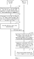
- FIG. 1 is a schematic flowchart of a reference signal transmission method according to an embodiment of this application. Refer to FIG. 1 . The method includes the following steps.
- Step 101 Determine an initial seed parameter of a pseudo-random sequence, and generate the pseudo-random sequence based on the initial seed parameter.
- the initial seed parameter is determined based on attribute information of a terminal device. Further, the initial seed parameter may be an integer determined based on the attribute information of the terminal device.
- Step 102 Determine a cyclic shift value based on the pseudo-random sequence, and determine a reference signal based on the cyclic shift value.
- Step 103 Send the reference signal to a network device.
- the reference signal may be an uplink sounding reference signal (sounding reference signal, SRS), an uplink demodulation reference signal (demodulation reference signal, DMRS), a phase tracking signal, or the like.
- SRS sounding reference signal
- DMRS demodulation reference signal
- phase tracking signal or the like.
- Step 101 to step 103 may be performed by the terminal device.
- Step 104 Determine an initial seed parameter of a pseudo-random sequence, and generate the pseudo-random sequence based on the initial seed parameter.
- Step 105 Determine a cyclic shift value based on the pseudo-random sequence, and determine a reference signal based on the cyclic shift value.
- Step 106 Detect a signal from a terminal device by using the reference signal.
- Step 104 to step 106 may be performed by a network device.
- the initial seed parameter of the pseudo-random sequence used for determining the cyclic shift value is determined based on the attribute information of the terminal device.
- the attribute information of the terminal device is information specific to the terminal device, and therefore, pseudo-random sequences used by different terminal devices to determine cyclic shift values are different.
- a difference between cyclic shift values used by any two terminal devices in a cell to determine reference signals can be randomized. Further, interference between reference signals sent by the terminal devices can be reduced, the interference is randomized, and channel time domain filtering performance is improved.
- step 101 to step 103 and step 104 to step 106 may be separately implemented.
- step 101 to step 103 may be performed, and from a perspective of the network device, in the foregoing method procedure, only step 104 to step 106 may be performed.
- the initial seed parameter c init of the pseudo-random sequence c (•) in formula (1) is actually a cell identity of a cell in which the terminal device is located.
- the initial seed parameter c init is the cell identity of the cell in which the terminal device is located, interference between reference signals finally determined by all terminal devices in the cell based on the initial seed parameter c init cannot be randomized, and consequently, channel time domain filtering performance deteriorates, and the interference between the reference signals is relatively large.
- the initial seed parameter of the pseudo-random sequence may be determined by using the attribute information of the terminal device. Descriptions are separately provided below.
- the attribute information of the terminal device may be specifically a feature used to indicate that one terminal device is different from another terminal device, or a feature that is common to one group of terminal devices but that is different from that of another terminal device.
- the following several possible implementations are merely used as examples for description, and do not limit the attribute information of the terminal device in this application.
- the attribute information of the terminal device includes a root indicator (Root indicator) q of a ZC sequence used for determining the reference signal.
- c init q.
- the initial seed parameter c init is equal to the root indicator q. Another case is not described.
- the attribute information of the terminal device includes a sequence identifier of the reference signal.
- c init n ID SRS .
- the initial seed parameter c init is equal to the sequence identifier n ID SRS . Another case is not described.
- different reference signal sequence identifiers n ID SRS may be configured for different terminal devices, so that cyclic shift hopping modes for reference signals sent by different terminal devices are different. In this way, interference is randomized.
- the attribute information of the terminal device may include identification information of the terminal device.
- the identification information may be dedicated identification information of the terminal device.
- the identification information may be a cell radio network temporary identity (cell radio network temporary identity, C-RNTI) of the terminal device, an international mobile subscriber identity (international mobile subscriber identity, IMSI) of the terminal device, or a temporary mobile station identifier (temporary mobile station identifier, TMSI) of the terminal device.
- the identification information may alternatively be identification information shared by a group of terminal devices. This is not limited in this application.
- the cyclic shift value may be determined by using a plurality of methods. Descriptions are separately described below.
- a first method is:
- n s , ⁇ ⁇ is a slot number (slot number), in a current system frame, of a slot in which the reference signal is sent, and the slot number is related to a subcarrier spacing, for example, when the subcarrier spacing is 15 kHz, the slot number is an integer from 0 to 9;
- ⁇ is a configured value of the subcarrier spacing, and corresponds one-to-one to a value of the sub
- Z is a fixed positive integer in a protocol, or Z is a positive integer determined based on the predefined rule and/or the configuration information of the network device.
- Z may be n RS cs , max , and n RS cs , max is a maximum cyclic shift value, namely, a maximum value of a cyclic shift value specified in a standard.
- n RS cs , max is a maximum cyclic shift value, namely, a maximum value of a cyclic shift value specified in a standard.
- cyclic shift values of reference signals sent by terminal devices in a same system frame can be randomized, so that interference, in the same system frame, between any two terminal devices that determine reference signals by using different ZC sequences can be randomized. In this way, time domain filtering performance for the reference signal is improved, and channel estimation accuracy is improved.
- a second method is:
- Z is a preset positive integer or a positive integer determined based on a predefined rule and/or configuration information of the network device, and for content of Z, refer to descriptions in formula (2), and details are not described herein again;
- ⁇ init is a predefined initial cyclic shift value or an initial cyclic shift value configured by the network device;
- N slot frame , ⁇ is a quantity of slots in each system frame, and the quantity of slots in each system frame is related to a subcarrier spacing; ⁇ is a configured value of the subcarrier spacing, and corresponds one-to-one to a value of the subcarrier spacing, and the subcarrier spacing may also be referred to as a subcarrier width; n f is a system frame number; n s , ⁇ ⁇ f is a slot number, in a current system frame, of a slot in which the reference signal is sent, and the slot number is related to the subcarrier spacing; l ′ ⁇ 0 , 1 , ... , N symb SRS ⁇ 1 is a symbol number, in a reference signal resource, of a symbol in which the reference signal is sent; N symb SRS is a predefined quantity of consecutive OFDM symbols or a quantity of consecutive OFDM symbols that are configured by the network device and that can be used to send the reference signal;
- cyclic shift values of reference signals sent by the terminal device on a same frequency domain resource for two or more consecutive times can be randomized, so that interference between reference signals sent twice or a plurality of times on a same time-frequency resource by any two terminal devices that determine the reference signals by using different ZC sequences can be randomized.
- time domain filtering performance for the reference signal is improved, and channel estimation accuracy is improved.
- a third method is:
- cyclic shift values of reference signals sent by the terminal device in any two reference signal sending cycles can be randomized, so that interference between reference signals of any two terminal devices that determine the reference signals by using different ZC sequences can be randomized. In this way, time domain filtering performance for the reference signal is improved, and channel estimation accuracy is improved.
- a fourth method is:
- ⁇ is a configured value of the subcarrier spacing, and corresponds one-to-one to a
- cyclic shift values of reference signals sent by the terminal device in any two or more symbols can be randomized, so that interference between reference signals sent in any two or more symbols by any two terminal devices that determine the reference signals by using different ZC sequences can be randomized.
- time domain filtering performance for the reference signal is improved, and channel estimation accuracy is improved.
- how to determine the reference signal based on the cyclic shift value is not limited in this embodiment of this application.
- the reference signal is an SRS
- the base sequence may be a sequence generated based on a ZC sequence, for example, is the ZC sequence or a sequence generated by performing cyclic shift on the ZC sequence.
- the cyclic shift value is determined based on the pseudo-random sequence.
- the cyclic shift value may alternatively be determined in another manner. This is described in detail below.
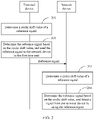
- FIG. 2 is a schematic flowchart of a reference signal transmission method according to an embodiment of this application. Refer to FIG. 2 . The method includes the following steps.
- Step 201 Determine a cyclic shift value of a reference signal.
- the cyclic shift value is determined based on a first cyclic shift interval, the first cyclic shift interval is determined from a first pattern based on information about a first time unit, the first pattern includes Y cyclic shift intervals, Y is an integer greater than 1, the first pattern is determined from X patterns, and X is a positive integer; or the cyclic shift value is determined based on a first cyclic shift step and the information about the first time unit, the first cyclic shift step is determined from Z cyclic shift steps, and Z is a positive integer; or the cyclic shift value is determined based on a first initial cyclic shift step, a first cyclic shift step gap, and the information about the first time unit, the first initial cyclic shift step is determined from Z initial cyclic shift steps, the first cyclic shift step gap is determined from Z cyclic shift step gaps, and Z is a positive integer.
- the information about the first time unit includes a number of a system frame in which the first time unit is located, a slot number, in a current system frame, of a slot in which the first time unit is located, and/or a symbol number, in a current slot, of a symbol in which the first time unit is located, and the first time unit is a time unit for sending the reference signal.
- the first pattern may be determined from the X patterns according to first indication information; the first cyclic shift step may be determined from the Z cyclic shift steps according to second indication information; the first initial cyclic shift step may be determined from the Z initial cyclic shift steps according to third indication information; and the first cyclic shift step gap may be determined from the Z cyclic shift step gaps according to fourth indication information.
- the first indication information to the fourth indication information may be sent by a network device to a terminal device.
- the first time unit may be a slot, an OFDM symbol, or a time unit such as a subframe or a system frame.
- the information about the first time unit includes a number of a system frame in which the first time unit is located, a slot number, in a current system frame, of a slot in which the first time unit is located, and/or a symbol number, in a current slot, of a symbol in which the first time unit is located may include the following cases:
- the first time unit is an OFDM symbol
- the information about the first time unit includes the number of the system frame in which the first time unit is located, the number, in the current system frame, of the slot in which the first time unit is located, a symbol number of the first time unit (namely, a symbol) in the current slot, and/or a symbol number of the first time unit (namely, a symbol) in a current reference signal resource.
- the case 3 may be applicable to formula (8), formula (10), and formula (12) that are described below.
- the case 4 may be applicable to formula (9), formula (11), and formula (13) that are described below.
- Step 202 Determine the reference signal based on the cyclic shift value, and send the reference signal to the network device in the first time unit.
- the reference signal may be an SRS, a DMRS, or the like.
- Step 201 and step 202 may be performed by the terminal device.
- Step 203 Determine a cyclic shift value of a reference signal.
- a method for determining the cyclic shift value in step 203 may be the same as that in step 201, and details are not described herein again.
- Step 204 Determine the reference signal based on the cyclic shift value, and detect a signal from the terminal device by using the reference signal.
- Step 203 and step 204 may be performed by the network device.
- step 201 and step 202 and step 203 and step 204 may be separately implemented.
- step 201 and step 202 may be performed, and from a perspective of the network device, in the foregoing method procedure, only step 203 and step 204 may be performed.
- the cyclic shift value may be determined by using a plurality of methods. Descriptions are separately described below.
- the cyclic shift value is determined based on a first cyclic shift step and information about the first time unit
- the first time unit is an OFDM symbol
- the information about the first time unit includes a number of a system frame in which the first time unit is located, a number, in a current system frame, of a slot in which the first time unit for sending the reference signal is located, and a symbol number of the first time unit in a reference signal resource, the symbol number belongs to a set 0 , 1 , ...
- ⁇ hopping is the first cyclic shift step; N slot frame , ⁇ is a quantity of slots in each system frame, and the quantity of slots is related to a subcarrier spacing; ⁇ is a configured value of the subcarrier spacing, and corresponds one-to-one to a value of the subcarrier spacing; n f is a system frame number; n s , ⁇ ⁇ is a slot number, in a current system frame, of a slot in which the reference signal is sent, and the slot number is related to the subcarrier spacing; L is a preset integer or a non-negative integer determined in a predetermined manner and/or based on configuration information of the network device, for example, L may be a slot offset value T offset of the reference signal; T SRS is a reference signal sending cycle; Z is a preset positive integer or a positive integer determined based on a predefined rule and/or the configuration information of the network device, and for content of Z, refer to descriptions in formula (2), and details are not described herein
- n f and n s , ⁇ ⁇ are the information about the first time unit.
- n f , n s , ⁇ ⁇ , and l ' are the information about the first time unit.
- the first cyclic shift step ⁇ hopping may be a value in a preset set.
- the preset set is ⁇ 0, 1, 2, ..., Z - 1 ⁇ .
- the network device may send second indication information to the terminal device, and the second indication information is used to indicate the first cyclic shift step. Therefore, the terminal device may determine the first cyclic shift step according to the second indication information.
- the network device preconfigures Z cyclic shift steps for the terminal device, and the second indication information is used to indicate a cyclic shift step in the Z cyclic shift steps.
- the second indication information may be an index value of the first cyclic shift step in the Z cyclic shift steps.
- the terminal device may determine the first cyclic shift step according to the second indication information.
- terminal devices that send reference signals on a same time-frequency resource may be classified into G groups based on base sequences for generating the reference signals, where G is a quantity of base sequences.
- Terminal devices belonging to a same group generate reference signals by using a same base sequence
- terminal devices belonging to different groups generate reference signals by using different base sequences.
- the network device may configure different values of ⁇ hopping for the G groups of terminal devices. In other words, a same value of ⁇ hopping is configured for terminal devices that determine reference signals by using a same base sequence, and different values of ⁇ hopping are configured for terminal devices that determine reference signals by using different base sequences.
- differences between cyclic shift of reference signals sent on any two same adjacent frequency domain resources by any two terminal devices that are in the G groups of terminal devices and that belong to different groups may be different, so that interference between reference signals of any two terminal devices that generate reference signal sequences based on different base sequences can be randomized, and channel measurement accuracy can be improved.
- the cyclic shift value is determined based on a first cyclic shift interval
- the first time unit is an OFDM symbol
- the first cyclic shift interval is determined from a first pattern based on information about the first time unit
- the information about the first time unit includes a number of a system frame in which the first time unit is located, a slot number, in a current system frame, of a slot in which the first time unit is located, and a symbol number of the first time unit in a reference signal resource
- the symbol number belongs to a set ⁇ 0, 1, ..., N symb SRS ⁇ 1 ⁇
- N symb SRS is a predefined quantity of consecutive OFDM symbols or a quantity of consecutive OFDM symbols that are configured by the network device and that can be used to send the reference signal
- Y is the first cyclic shift interval
- the first pattern is a set including Y cyclic shift intervals
- the first pattern is [ ⁇ 0 , ⁇ 1 , ⁇ 2 , ..., ⁇ Y -1 ]
- Y is an integer greater than 1
- each cyclic shift interval included in the first pattern is an integer.
- n f and n s , ⁇ ⁇ are the information about the first time unit.
- n f , n s , ⁇ ⁇ , and l ' are the information about the first time unit.
- the Y cyclic shift intervals included in the first pattern may be predefined integers.
- X patterns may be predefined, X is a positive integer, and each of the X patterns includes Y cyclic shift intervals.
- the network device may send first indication information to the terminal device, where the first indication information is used to indicate one pattern in the X patterns, and the terminal device may determine the first pattern from the X patterns according to the first indication information.
- Y cyclic shift intervals included in an x th pattern in the predefined X patterns are: [ ⁇ ⁇ 0 ⁇ x / Z ⁇ x mod Z , ⁇ ⁇ 1 ⁇ x / Z ⁇ x mod Z , ... , ⁇ ⁇ Y ⁇ 1 ⁇ x / Z ⁇ x mod Z ].
- the X patterns may be any X patterns that meet the following conditions:
- y ⁇ 1 , ... , Y ⁇ 1 , x ⁇ ⁇ 0, 1, ..., Z -1 ⁇ may be determined by the terminal device based on a predefined rule and/or the configuration information of the network device, where ⁇ 0 % ⁇ x / Z ⁇ x mod Z is any value in a set ⁇ 0, 1, ..., Z -1 ⁇ , and different x may correspond to a same value or different values of ⁇ ⁇ 0 ⁇ x / Z ⁇ x mod Z .
- ⁇ ⁇ ⁇ 0 ⁇ x / Z ⁇ x mod Z 0
- y ⁇ 1 , ... , Y ⁇ 1 , x ⁇ ⁇ 0, 1, ..., Z -1 ⁇ is an integer that meets the condition 2 and that belongs to the set ⁇ 0, 1, ..., Z -1 ⁇ .
- ⁇ b y ⁇ x / Z ⁇ x mod Z x mod Z
- the terminal device may determine a value of ⁇ b y ⁇ x / Z ⁇ x mod Z
- the terminal device may determine a value of ⁇ ⁇ ⁇ y ⁇ x / Z ⁇ x mod Z
- terminal devices that send reference signals on a same time-frequency resource may be classified into G groups based on base sequences for generating the reference signals, where G is a quantity of base sequences.
- Terminal devices belonging to a same group generate reference signals by using a same base sequence, and terminal devices belonging to different groups generate reference signals by using different base sequences.
- the network device may configure different cyclic shift hopping patterns, namely, different values of x, for the G groups of terminal devices.
- a same cyclic shift hopping pattern namely, a same value of x
- different cyclic shift patterns namely, different values of x
- G is less than or equal to Z
- differences between cyclic shift of reference signals sent on any two same adjacent frequency domain resources by any two terminal devices that are in the G groups of terminal devices and that belong to different groups are different.
- interference between reference signals of any two terminal devices that generate reference signal sequences based on different base sequences can be randomized, so that channel measurement accuracy can be improved.
- the cyclic shift value is determined based on a first initial cyclic shift step, a first cyclic shift step value, and information about the first time unit
- the first time unit is an OFDM symbol
- the information about the first time unit includes a number of a system frame in which the first time unit is located, a slot number, in a current system frame, of a slot in which the first time unit is located, and a symbol number of the first time unit in a reference signal resource, the symbol number belongs to a set 0 , 1 , ...
- the first initial cyclic shift step ⁇ h init may be a value in a first preset set.
- the first preset set is ⁇ 0, 1, 2, ..., Z -1 ⁇ .
- the first cyclic shift step gap ⁇ h gap may be a value in a second preset set.
- the second preset set is ⁇ 0, 1, 2, ..., Z -1 ⁇ .
- n f and n s , ⁇ ⁇ are the information about the first time unit.
- n f , n s , ⁇ ⁇ , and l ' are the information about the first time unit.
- the network device sends third indication information to the terminal device, and indicates the first initial cyclic shift step to the terminal device by using the third indication information.
- the network device preconfigures Z initial cyclic shift steps, and the third indication information is used to indicate one initial cyclic shift step in the Z initial cyclic shift steps. Therefore, the terminal device may determine the first initial cyclic shift step from the Z initial cyclic shift steps according to the third indication information.
- the network device may further send fourth indication information to the terminal device, and indicate the first cyclic shift step gap to the terminal device by using the fourth indication information.
- the network device preconfigures Z first cyclic shift step gaps, and the fourth indication information is used to indicate one cyclic shift step gap in the Z first cyclic shift step gaps. Therefore, the terminal device may determine the first cyclic shift step gap from the Z first cyclic shift step gaps according to the fourth indication information.
- terminal devices that send reference signals on a same time-frequency resource may be classified into G groups based on base sequences for generating the reference signals, where G is a quantity of base sequences.
- Terminal devices belonging to a same group generate reference signals by using a same base sequence
- terminal devices belonging to different groups generate reference signals by using different base sequences.
- the network device may configure different initial cyclic shift steps and/or different cyclic shift step gaps for the G groups of terminal devices.
- a same initial cyclic shift step and a same cyclic shift step gap are configured for terminal devices that determine reference signals by using a same base sequence
- different initial cyclic shift steps and/or different cyclic shift step gaps are configured for terminal devices that determine reference signals by using different base sequences.
- G is less than or equal to Z
- differences between cyclic shift of reference signals sent on any two same adjacent frequency domain resources by any two terminal devices that are in the G groups of terminal devices and that belong to different groups are different.
- interference between reference signals of any two terminal devices that generate reference signal sequences based on different base sequences can be randomized, so that channel measurement accuracy can be improved.
- G is greater than Z and less than Z 2
- differences between cyclic shift of reference signals sent on any three same adjacent frequency domain resources by any two terminal devices that are in the G groups of terminal devices and that belong to different groups are not entirely the same. In other words, when coherent bandwidth is greater than or equal to two times the reference signal sending cycle, channel measurement accuracy can be improved through time domain filtering.
- the cyclic shift value needs to be determined first.
- An embodiment of this application further provides a method.
- the cyclic shift value is determined based on a predefined rule and/or configuration information of the network device.
- orthogonal cover code is added to reference signals, so that interference between the reference signals is randomized. Detailed descriptions are provided below.
- Step 1 The terminal device generates a reference signal.
- Step 2 The terminal device sends the reference signal.
- Step 3 The network device generates a reference signal.
- Step 4 The network device detects a signal from the terminal device by using the reference signal.
- C Z root , y (•) is an orthogonal variable spreading factor (Orthogonal Variable Spreading Factor, OVSF) sequence;
- L is determined by using a predefined rule or determined based on configuration information of the network device, for example, L is a slot offset T offset of the reference signal;
- y is an integer greater than or equal to 0 and less than Z root , and is determined based on the predefined rule and/or based on the configuration information of the network device, and optionally, the network device may configure a same value of y for terminal devices that determine reference signals by using a same base sequence;
- Z root is a positive integer and is determined based on the predefined rule and/or the configuration information of the network device.
- terminal devices that send reference signals on a same time-frequency resource may be classified into G groups based on base sequences for generating the reference signals, where G is a quantity of base sequences.
- Terminal devices belonging to a same group generate reference signals by using a same base sequence
- terminal devices belonging to different groups generate reference signals by using different base sequences.
- the network device may allocate different values of y for terminal devices that belong to different groups, and then, time domain filtering is performed on Z root consecutive reference signal sending cycles, to eliminate interference exerted on a reference signal sent by any one of the G terminal devices by a reference signal sent by another terminal device in the G terminal devices.
- channel measurement accuracy can be improved through time domain filtering.
- the methods and the operations implemented by the terminal device may be alternatively implemented by a component (for example, a chip or a circuit) that may be used in the terminal device
- the methods and the operations implemented by the network device may be alternatively implemented by a component (for example, a chip or a circuit) that may be used in the network device.
- each network element includes a corresponding hardware structure and/or software module for implementing each function.
- units and algorithm steps may be implemented by hardware or a combination of hardware and computer software in the present invention. Whether a function is performed by hardware or hardware driven by computer software depends on a particular application and a design constraint of the technical solutions. A person skilled in the art may use different methods to implement the described functions for each particular application, but it should not be considered that the implementation goes beyond the scope of the present invention.
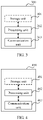
- FIG. 3 is a possible example block diagram of a communication apparatus according to this application.
- the apparatus 300 may exist in a form of software or hardware.
- the apparatus 300 may include a processing unit 302 and a communication unit 303.
- the communication unit 303 may include a receiving unit and a sending unit.
- the processing unit 302 is configured to control and manage an action of the apparatus 300.
- the communication unit 303 is configured to support the apparatus 300 in communicating with another network entity.
- the apparatus 300 may further include a storage unit 301, configured to store program code and data of the apparatus 300.
- the processing unit 302 may be a processor or a controller, such as a general-purpose central processing unit (central processing unit, CPU), a general-purpose processor, a digital signal processor (digital signal processor, DSP), an application-specific integrated circuit (application-specific integrated circuit, ASIC), a field programmable gate array (field programmable gate array, FPGA), or another programmable logical device, a transistor logical device, a hardware component, or any combination thereof.
- the processing unit may implement or execute various example logical blocks, modules, and circuits described with reference to content disclosed in this application.
- the processor may be a combination of processors implementing a computing function, for example, a combination of one or more microprocessors, or a combination of a DSP and a microprocessor.
- the storage unit 301 may be a memory.
- the communication unit 303 is an interface circuit of the apparatus, and is configured to receive a signal from another apparatus. For example, when the apparatus is implemented in a form of a chip, the communication unit 303 is an interface circuit used by the chip to receive a signal from another chip or apparatus, or is an interface circuit used by the chip to send a signal to another chip or apparatus.
- the apparatus 300 may be the terminal device in any one of the foregoing embodiments, or may be a chip used in the terminal device.
- the processing unit 302 may be, for example, a processor
- the communication unit 303 may be, for example, a transceiver.
- the transceiver may include a radio frequency circuit
- the storage unit may be, for example, a memory.
- the processing unit 302 may be, for example, a processor
- the communication unit 303 may be, for example, an input/output interface, a pin, or a circuit.
- the processing unit 302 may execute computer-executable instructions stored in the storage unit.
- the storage unit is a storage unit inside the chip, such as a register or a buffer.
- the storage unit may be a storage unit that is inside the terminal device and that is located outside the chip, such as a read-only memory (read-only memory, ROM), another type of static storage device that can store static information and instructions, or a random access memory (random access memory, RAM).
- ROM read-only memory
- RAM random access memory
- the apparatus 300 may be the network device in any one of the foregoing embodiments, or may be a chip used in the network device.
- the processing unit 302 may be, for example, a processor
- the communication unit 303 may be, for example, a transceiver.
- the apparatus 300 is a terminal device.
- the processing unit 302 is configured to: determine an initial seed parameter of a pseudo-random sequence, and generate the pseudo-random sequence based on the initial seed parameter, where the initial seed parameter is determined based on attribute information of the terminal device; and determine a cyclic shift value based on the pseudo-random sequence, and determine a reference signal based on the cyclic shift value.
- the communication unit 303 is configured to send the reference signal to a network device.
- the apparatus 300 is a network device.
- the communication unit 303 is configured to receive a signal from a terminal device.
- the processing unit 302 is configured to: determine an initial seed parameter of a pseudo-random sequence, and generate the pseudo-random sequence based on the initial seed parameter, where the initial seed parameter is determined based on attribute information of the terminal device; determine a cyclic shift value based on the pseudo-random sequence, and determine a reference signal based on the cyclic shift value; and detect a signal from the terminal device by using the reference signal.
- the attribute information includes a root indicator of a ZC sequence used for determining the reference signal.
- the attribute information includes a sequence identifier of the reference signal.
- Z is n RS cs , max , and n RS cs , max is a maximum cyclic shift value.
- FIG. 4 is a possible example block diagram of a communication apparatus according to this application.
- the apparatus 400 may exist in a form of software or hardware.
- the apparatus 400 may include a processing unit 402 and a communication unit 403.
- the communication unit 403 may include a receiving unit and a sending unit.
- the processing unit 402 is configured to control and manage an action of the apparatus 400.
- the communication unit 403 is configured to support the apparatus 400 in communicating with another network entity.
- the apparatus 400 may further include a storage unit 401, configured to store program code and data of the apparatus 400.
- the processing unit 402 may be a processor or a controller, for example, a CPU, a general-purpose processor, a DSP, an ASIC, an FPGA or another programmable logic device, a transistor logic device, a hardware component, or any combination thereof.
- the processing unit may implement or execute various example logical blocks, modules, and circuits described with reference to content disclosed in this application.
- the processor may be a combination of processors implementing a computing function, for example, a combination of one or more microprocessors, or a combination of a DSP and a microprocessor.
- the storage unit 401 may be a memory.
- the communication unit 403 is an interface circuit of the apparatus, and is configured to receive a signal from another apparatus. For example, when the apparatus is implemented in a form of a chip, the communication unit 403 is an interface circuit used by the chip to receive a signal from another chip or apparatus, or is an interface circuit used by the chip to send a signal to another chip or apparatus.
- the apparatus 400 may be the network device in any one of the foregoing embodiments, or may be a chip used in the network device.
- the processing unit 402 may be, for example, a processor
- the communication unit 403 may be, for example, a transceiver.
- the apparatus 400 may be the terminal device in any one of the foregoing embodiments, or may be a chip used in the terminal device.
- the processing unit 402 may be, for example, a processor
- the communication unit 403 may be, for example, a transceiver.
- the transceiver may include a radio frequency circuit
- the storage unit may be, for example, a memory.
- the processing unit 402 may be, for example, a processor
- the communication unit 403 may be, for example, an input/output interface, a pin, or a circuit.
- the processing unit 402 may execute computer-executable instructions stored in the storage unit.
- the storage unit is a storage unit inside the chip, such as a register or a buffer.
- the storage unit may be a storage unit that is inside the network device and that is located outside the chip, for example, a ROM, another type of static storage device that can store static information and instructions, or a RAM
- the apparatus 400 is a terminal device.
- the processing unit 402 is configured to: determine a cyclic shift value, where the cyclic shift value is determined based on a first frequency hopping parameter, the first frequency hopping parameter is determined from a first pattern based on information about a first time unit, and the first pattern includes at least two frequency hopping parameters; the cyclic shift value is determined based on a first cyclic shift step and the information about the first time unit; or the cyclic shift value is determined based on a first initial cyclic shift step, a first cyclic shift step gap, and the information about the first time unit, where the information about the first time unit includes a number of a system frame in which the first time unit is located and/or a slot number of a slot in which the first time unit is located, and the first time unit is a time unit for sending a reference signal; and determine the reference signal based on the cyclic shift value.
- the communication unit 403 is configured to send the reference signal to a network device in the first time unit.
- the apparatus 400 is a network device.
- the communication unit 403 is configured to receive a signal from a terminal device.
- the processing unit 402 is configured to: determine a cyclic shift value of a reference signal, where the cyclic shift value is determined based on a first frequency hopping parameter, the first frequency hopping parameter is determined from a first pattern based on information about a first time unit, and the first pattern includes at least two frequency hopping parameters; the cyclic shift value is determined based on a first cyclic shift step and the information about the first time unit; or the cyclic shift value is determined based on a first initial cyclic shift step, a first cyclic shift step gap, and the information about the first time unit, where the information about the first time unit includes a number of a system frame in which the first time unit is located and/or a slot number of a slot in which the first time unit is located, and the first time unit is a time unit for sending the reference signal; determine the reference signal based on the cyclic shift value; and detect a signal from the terminal device by using the reference signal.
- the apparatus 400 when the apparatus 400 is a terminal device or a network device, the following implementation methods are further included:
- the first pattern is determined from X patterns according to first indication information, and the first indication information is sent by the network device to the terminal device;
- the cyclic shift value is determined based on a first cyclic shift interval
- the first cyclic shift interval is determined from the first pattern based on the information about the first time unit
- the information about the first time unit includes the number of the system frame in which the first time unit is located and a slot number, in a current system frame, of the slot in which the first time unit is located
- N T SRS ⁇ N slot frame , ⁇ n ⁇ + n s , ⁇ ⁇ ⁇ L T SRS ⁇ N slot frame , ⁇ is a quantity of slots in each system frame; n f is a system frame number; n s , ⁇ ⁇ is a slot number, in the current system frame, of
- Z is n RS cs , max , and n RS cs , max is a maximum cyclic shift value.
- the reference signal in this embodiment of this application is a downlink reference signal, such as a downlink DMRS and a phase tracking signal.
- the reference signal sending method provided in the embodiments of this application may be performed by the network device.
- the signal detection method provided in the embodiments of this application may be performed by the terminal device.
- FIG. 5 is a schematic diagram of a communication apparatus according to this application.
- the apparatus may be the terminal device or the network device in the foregoing embodiments.
- the apparatus 500 includes a processor 502, a communication interface 503, and a memory 501.
- the apparatus 500 may further include a communication line 504.
- the communication interface 503, the processor 502, and the memory 501 may be connected to each other by using the communication line 504.
- the communication line 504 may be a peripheral component interconnect (peripheral component interconnect, PCI for short) bus, an extended industry standard architecture (extended industry standard architecture, EISA for short) bus, or the like.
- the communication line 504 may be classified into an address bus, a data bus, a control bus, and the like. For ease of representation, only one thick line is used to represent the bus in FIG. 5 , but this does not mean that there is only one bus or only one type of bus.
- the processor 502 may be a CPU, a microprocessor, an ASIC, or one or more integrated circuits configured to control program execution in the solutions of this application.
- the communication interface 503 uses any apparatus like a transceiver, and is configured to communicate with another device or a communication network, such as the Ethernet, a radio access network (radio access network, RAN), a wireless local area network (wireless local area network, WLAN), or a wired access network.
- a radio access network radio access network
- WLAN wireless local area network
- wired access network any apparatus like a transceiver, and is configured to communicate with another device or a communication network, such as the Ethernet, a radio access network (radio access network, RAN), a wireless local area network (wireless local area network, WLAN), or a wired access network.
- the memory 501 may be a ROM, another type of static storage device that can store static information and instructions, a RAM, or another type of dynamic storage device that can store information and instructions, or may be an electrically erasable programmable read-only memory (electrically erasable programmable read-only memory, EEPROM), a compact disc read-only memory (compact disc read-only memory, CD-ROM) or another compact disc storage, an optical disc storage (including a compact disc, a laser disc, an optical disc, a digital versatile disc, a Blu-ray disc, and the like), a magnetic disk storage medium or another magnetic storage device, or any other medium that can be configured to carry or store expected program code in a form of an instruction or a data structure and that can be accessed by a computer, but is not limited thereto.
- the memory may exist independently and is connected to the processor by using the communication line 504. The memory may alternatively be integrated with the processor.
- the memory 501 is configured to store computer-executable instructions for executing the solutions of this application, and the processor 502 controls the execution.
- the processor 502 is configured to execute the computer-executable instruction stored in the memory 501, to implement the communication method provided in FIG. 2 or FIG. 3 in the foregoing embodiments of this application.
- the computer-executable instructions in this embodiment of this application may also be referred to as application program code. This is not specifically limited in this embodiment of this application.
- At least one means any combination of these items, including a single item (piece) or any combination of a plurality of items (pieces).
- at least one (piece or type) of a, b, or c may represent a, b, c, a and b, a and c, b and c, or a, b, and c, where a, b, and c may be in a singular or plural form.
- a plurality of' means two or more, and another quantifier is similar to this.
- an element (element) appearing in singular forms "a", “an” and “the” does not mean “one or only one” but “one or more” unless otherwise specified in the context.
- a device means one or more such devices.
- this application may be provided as methods, systems, or computer program products. Therefore, this application may use a form of hardware only embodiments, software only embodiments, or embodiments with a combination of software and hardware. Moreover, this application may use a form of a computer program product that is implemented on one or more computer-usable storage media (including but not limited to a disk memory, an optical memory, and the like) that include computer-usable program code.
- a computer-usable storage media including but not limited to a disk memory, an optical memory, and the like
- These computer program instructions may be provided for a general-purpose computer, a dedicated computer, an embedded processor, or a processor of another programmable data processing device to generate a machine, so that the instructions executed by the computer or the processor of the another programmable data processing device generate an apparatus for implementing a specific function in one or more procedures in the flowcharts and/or in one or more blocks in the block diagrams.
- These computer program instructions may alternatively be stored in a computer-readable memory that can indicate a computer or another programmable data processing device to work in a specific manner, so that the instructions stored in the computer-readable memory generate an artifact that includes an instruction apparatus.
- the instruction apparatus implements a specific function in one or more procedures in the flowcharts and/or in one or more blocks in the block diagrams.
Landscapes
- Engineering & Computer Science (AREA)
- Signal Processing (AREA)
- Computer Networks & Wireless Communication (AREA)
- Mobile Radio Communication Systems (AREA)
Applications Claiming Priority (1)
| Application Number | Priority Date | Filing Date | Title |
|---|---|---|---|
| PCT/CN2019/105198 WO2021046724A1 (zh) | 2019-09-10 | 2019-09-10 | 一种参考信号发送、信号检测方法及装置 |
Related Child Applications (1)
| Application Number | Title | Priority Date | Filing Date |
|---|---|---|---|
| EP23200390.5 Division-Into | 2023-09-28 |
Publications (3)
| Publication Number | Publication Date |
|---|---|
| EP4068714A1 true EP4068714A1 (de) | 2022-10-05 |
| EP4068714A4 EP4068714A4 (de) | 2022-10-05 |
| EP4068714B1 EP4068714B1 (de) | 2023-11-08 |
Family
ID=74866689
Family Applications (1)
| Application Number | Title | Priority Date | Filing Date |
|---|---|---|---|
| EP19944848.1A Active EP4068714B1 (de) | 2019-09-10 | 2019-09-10 | Referenzsignalsende- und signaldetektionsverfahren und -vorrichtung |
Country Status (4)
| Country | Link |
|---|---|
| US (1) | US11882071B2 (de) |
| EP (1) | EP4068714B1 (de) |
| CN (1) | CN114365458B (de) |
| WO (1) | WO2021046724A1 (de) |
Families Citing this family (5)
| Publication number | Priority date | Publication date | Assignee | Title |
|---|---|---|---|---|
| EP4614907A4 (de) * | 2022-11-06 | 2025-12-17 | Beijing Xiaomi Mobile Software Co Ltd | Übertragungsverfahren und -vorrichtung für klangreferenzsignal und medium |
| JP2026506337A (ja) * | 2023-01-13 | 2026-02-24 | 日本電気株式会社 | ユーザ機器及び方法 |
| CN118432779A (zh) * | 2023-02-01 | 2024-08-02 | 华为技术有限公司 | 一种测量参考信号srs传输方法及装置 |
| CN117938181B (zh) * | 2024-02-26 | 2024-10-11 | 摩尔线程智能科技(北京)有限责任公司 | 伪随机序列一致性检测方法、装置和存储介质 |
| CN121397576A (zh) * | 2024-07-22 | 2026-01-23 | 华为技术有限公司 | 一种通信方法及装置 |
Family Cites Families (8)
| Publication number | Priority date | Publication date | Assignee | Title |
|---|---|---|---|---|
| CN102282817B (zh) * | 2008-08-19 | 2014-07-02 | 韩国电子通信研究院 | 用于接收和发送应答/无应答信息的方法 |
| EP3176976A1 (de) * | 2011-08-12 | 2017-06-07 | Telefonaktiebolaget LM Ericsson (publ) | Verfahren und vorrichtungen zur verwaltung von referenzsignalen in einem mobilfunknetz |
| EP2817933B1 (de) * | 2012-02-20 | 2020-04-01 | LG Electronics Inc. | Verfahren und vorrichtung zur übertragung von uplink-steuersignalen in einem drahtlosen kommunikationssystem |
| CN104618985B (zh) * | 2013-11-01 | 2019-09-24 | 中兴通讯股份有限公司 | 设备发现信号的发送方法、装置、设备及系统 |
| CN104853339A (zh) * | 2014-02-19 | 2015-08-19 | 中兴通讯股份有限公司 | 一种信号处理的方法及装置 |
| CN108631976B (zh) * | 2017-03-23 | 2021-07-16 | 华为技术有限公司 | 一种通信方法及装置 |
| US20190149298A1 (en) * | 2017-11-15 | 2019-05-16 | Mediatek Inc. | Reference Signals With Improved Cross-Correlation Properties In Wireless Communications |
| CN107995679B (zh) * | 2018-01-30 | 2019-05-17 | 创新维度科技(北京)有限公司 | 一种物联网的下行数据传输和下行数据接收方法 |
-
2019
- 2019-09-10 EP EP19944848.1A patent/EP4068714B1/de active Active
- 2019-09-10 CN CN201980099949.2A patent/CN114365458B/zh active Active
- 2019-09-10 WO PCT/CN2019/105198 patent/WO2021046724A1/zh not_active Ceased
-
2022
- 2022-03-09 US US17/690,738 patent/US11882071B2/en active Active
Also Published As
| Publication number | Publication date |
|---|---|
| US11882071B2 (en) | 2024-01-23 |
| CN114365458B (zh) | 2023-09-29 |
| US20220200760A1 (en) | 2022-06-23 |
| EP4068714B1 (de) | 2023-11-08 |
| CN114365458A (zh) | 2022-04-15 |
| EP4068714A4 (de) | 2022-10-05 |
| WO2021046724A1 (zh) | 2021-03-18 |
Similar Documents
| Publication | Publication Date | Title |
|---|---|---|
| US11882071B2 (en) | Reference signal sending method, signal detection method, and apparatus | |
| US20240179038A1 (en) | Method and device for transmitting measurement reference signal | |
| US11323973B2 (en) | Information sending and receiving method and related device | |
| US12476758B2 (en) | Signal sending method, signal detection method, and apparatus | |
| CN109462891B (zh) | 检测窗指示方法及装置 | |
| US11916834B2 (en) | Method and apparatus for transmitting a reference signal | |
| EP4192091A1 (de) | Verfahren zur kombination von interferenzunterdrückung, ressourcenanzeigeverfahren und kommunikationsvorrichtung | |
| CN106063355A (zh) | 一种传输消息的方法和装置 | |
| EP3432529A1 (de) | Verfahren zum senden eines signals, endgerätvorrichtung und netzwerkvorrichtung | |
| US10819487B2 (en) | Pilot transmission method, terminal device, and network device | |
| EP4513809A1 (de) | Referenzsignalübertragungsverfahren und -vorrichtung sowie speichermedium | |
| CN115428378B (zh) | 通信的方法和装置 | |
| US10763948B2 (en) | Signal sending method and apparatus, and signal receiving method and apparatus | |
| US20260039524A1 (en) | Communication method and apparatus | |
| EP3993291A1 (de) | Synchronisationsignalübertragungsverfahren und kommunikationsvorrichtung | |
| US20250175373A1 (en) | Reference signal transmission method and communication apparatus | |
| EP3422762A1 (de) | Signalübertragungsverfahren und basisstation dafür | |
| EP3691369A1 (de) | Nachrichtenübertragungsverfahren und -vorrichtung |
Legal Events
| Date | Code | Title | Description |
|---|---|---|---|
| STAA | Information on the status of an ep patent application or granted ep patent |
Free format text: STATUS: THE INTERNATIONAL PUBLICATION HAS BEEN MADE |
|
| PUAI | Public reference made under article 153(3) epc to a published international application that has entered the european phase |
Free format text: ORIGINAL CODE: 0009012 |
|
| STAA | Information on the status of an ep patent application or granted ep patent |
Free format text: STATUS: REQUEST FOR EXAMINATION WAS MADE |
|
| PUAB | Information related to the publication of an a document modified or deleted |
Free format text: ORIGINAL CODE: 0009199EPPU |
|
| PUAI | Public reference made under article 153(3) epc to a published international application that has entered the european phase |
Free format text: ORIGINAL CODE: 0009012 |
|
| 17P | Request for examination filed |
Effective date: 20220330 |
|
| A4 | Supplementary search report drawn up and despatched |
Effective date: 20220905 |
|
| AK | Designated contracting states |
Kind code of ref document: A1 Designated state(s): AL AT BE BG CH CY CZ DE DK EE ES FI FR GB GR HR HU IE IS IT LI LT LU LV MC MK MT NL NO PL PT RO RS SE SI SK SM TR |
|
| DAV | Request for validation of the european patent (deleted) | ||
| DAX | Request for extension of the european patent (deleted) | ||
| GRAP | Despatch of communication of intention to grant a patent |
Free format text: ORIGINAL CODE: EPIDOSNIGR1 |
|
| STAA | Information on the status of an ep patent application or granted ep patent |
Free format text: STATUS: GRANT OF PATENT IS INTENDED |
|
| RIC1 | Information provided on ipc code assigned before grant |
Ipc: H04L 5/00 20060101ALI20230406BHEP Ipc: H04L 27/26 20060101AFI20230406BHEP |
|
| INTG | Intention to grant announced |
Effective date: 20230502 |
|
| GRAS | Grant fee paid |
Free format text: ORIGINAL CODE: EPIDOSNIGR3 |
|
| GRAA | (expected) grant |
Free format text: ORIGINAL CODE: 0009210 |
|
| STAA | Information on the status of an ep patent application or granted ep patent |
Free format text: STATUS: THE PATENT HAS BEEN GRANTED |
|
| AK | Designated contracting states |
Kind code of ref document: B1 Designated state(s): AL AT BE BG CH CY CZ DE DK EE ES FI FR GB GR HR HU IE IS IT LI LT LU LV MC MK MT NL NO PL PT RO RS SE SI SK SM TR |
|
| REG | Reference to a national code |
Ref country code: GB Ref legal event code: FG4D |
|
| REG | Reference to a national code |
Ref country code: CH Ref legal event code: EP |
|
| REG | Reference to a national code |
Ref country code: DE Ref legal event code: R096 Ref document number: 602019041289 Country of ref document: DE |
|
| REG | Reference to a national code |
Ref country code: IE Ref legal event code: FG4D |
|
| REG | Reference to a national code |
Ref country code: LT Ref legal event code: MG9D |
|
| REG | Reference to a national code |
Ref country code: NL Ref legal event code: MP Effective date: 20231108 |
|
| PG25 | Lapsed in a contracting state [announced via postgrant information from national office to epo] |
Ref country code: GR Free format text: LAPSE BECAUSE OF FAILURE TO SUBMIT A TRANSLATION OF THE DESCRIPTION OR TO PAY THE FEE WITHIN THE PRESCRIBED TIME-LIMIT Effective date: 20240209 |
|
| PG25 | Lapsed in a contracting state [announced via postgrant information from national office to epo] |
Ref country code: IS Free format text: LAPSE BECAUSE OF FAILURE TO SUBMIT A TRANSLATION OF THE DESCRIPTION OR TO PAY THE FEE WITHIN THE PRESCRIBED TIME-LIMIT Effective date: 20240308 |
|
| PG25 | Lapsed in a contracting state [announced via postgrant information from national office to epo] |
Ref country code: LT Free format text: LAPSE BECAUSE OF FAILURE TO SUBMIT A TRANSLATION OF THE DESCRIPTION OR TO PAY THE FEE WITHIN THE PRESCRIBED TIME-LIMIT Effective date: 20231108 |
|
| REG | Reference to a national code |
Ref country code: AT Ref legal event code: MK05 Ref document number: 1630644 Country of ref document: AT Kind code of ref document: T Effective date: 20231108 |
|
| PG25 | Lapsed in a contracting state [announced via postgrant information from national office to epo] |
Ref country code: NL Free format text: LAPSE BECAUSE OF FAILURE TO SUBMIT A TRANSLATION OF THE DESCRIPTION OR TO PAY THE FEE WITHIN THE PRESCRIBED TIME-LIMIT Effective date: 20231108 |
|
| PG25 | Lapsed in a contracting state [announced via postgrant information from national office to epo] |
Ref country code: AT Free format text: LAPSE BECAUSE OF FAILURE TO SUBMIT A TRANSLATION OF THE DESCRIPTION OR TO PAY THE FEE WITHIN THE PRESCRIBED TIME-LIMIT Effective date: 20231108 |
|
| PG25 | Lapsed in a contracting state [announced via postgrant information from national office to epo] |
Ref country code: ES Free format text: LAPSE BECAUSE OF FAILURE TO SUBMIT A TRANSLATION OF THE DESCRIPTION OR TO PAY THE FEE WITHIN THE PRESCRIBED TIME-LIMIT Effective date: 20231108 |
|
| PG25 | Lapsed in a contracting state [announced via postgrant information from national office to epo] |
Ref country code: NL Free format text: LAPSE BECAUSE OF FAILURE TO SUBMIT A TRANSLATION OF THE DESCRIPTION OR TO PAY THE FEE WITHIN THE PRESCRIBED TIME-LIMIT Effective date: 20231108 Ref country code: LT Free format text: LAPSE BECAUSE OF FAILURE TO SUBMIT A TRANSLATION OF THE DESCRIPTION OR TO PAY THE FEE WITHIN THE PRESCRIBED TIME-LIMIT Effective date: 20231108 Ref country code: IS Free format text: LAPSE BECAUSE OF FAILURE TO SUBMIT A TRANSLATION OF THE DESCRIPTION OR TO PAY THE FEE WITHIN THE PRESCRIBED TIME-LIMIT Effective date: 20240308 Ref country code: GR Free format text: LAPSE BECAUSE OF FAILURE TO SUBMIT A TRANSLATION OF THE DESCRIPTION OR TO PAY THE FEE WITHIN THE PRESCRIBED TIME-LIMIT Effective date: 20240209 Ref country code: ES Free format text: LAPSE BECAUSE OF FAILURE TO SUBMIT A TRANSLATION OF THE DESCRIPTION OR TO PAY THE FEE WITHIN THE PRESCRIBED TIME-LIMIT Effective date: 20231108 Ref country code: BG Free format text: LAPSE BECAUSE OF FAILURE TO SUBMIT A TRANSLATION OF THE DESCRIPTION OR TO PAY THE FEE WITHIN THE PRESCRIBED TIME-LIMIT Effective date: 20240208 Ref country code: AT Free format text: LAPSE BECAUSE OF FAILURE TO SUBMIT A TRANSLATION OF THE DESCRIPTION OR TO PAY THE FEE WITHIN THE PRESCRIBED TIME-LIMIT Effective date: 20231108 Ref country code: PT Free format text: LAPSE BECAUSE OF FAILURE TO SUBMIT A TRANSLATION OF THE DESCRIPTION OR TO PAY THE FEE WITHIN THE PRESCRIBED TIME-LIMIT Effective date: 20240308 |
|
| PG25 | Lapsed in a contracting state [announced via postgrant information from national office to epo] |
Ref country code: SE Free format text: LAPSE BECAUSE OF FAILURE TO SUBMIT A TRANSLATION OF THE DESCRIPTION OR TO PAY THE FEE WITHIN THE PRESCRIBED TIME-LIMIT Effective date: 20231108 Ref country code: RS Free format text: LAPSE BECAUSE OF FAILURE TO SUBMIT A TRANSLATION OF THE DESCRIPTION OR TO PAY THE FEE WITHIN THE PRESCRIBED TIME-LIMIT Effective date: 20231108 Ref country code: PL Free format text: LAPSE BECAUSE OF FAILURE TO SUBMIT A TRANSLATION OF THE DESCRIPTION OR TO PAY THE FEE WITHIN THE PRESCRIBED TIME-LIMIT Effective date: 20231108 Ref country code: NO Free format text: LAPSE BECAUSE OF FAILURE TO SUBMIT A TRANSLATION OF THE DESCRIPTION OR TO PAY THE FEE WITHIN THE PRESCRIBED TIME-LIMIT Effective date: 20240208 Ref country code: LV Free format text: LAPSE BECAUSE OF FAILURE TO SUBMIT A TRANSLATION OF THE DESCRIPTION OR TO PAY THE FEE WITHIN THE PRESCRIBED TIME-LIMIT Effective date: 20231108 Ref country code: HR Free format text: LAPSE BECAUSE OF FAILURE TO SUBMIT A TRANSLATION OF THE DESCRIPTION OR TO PAY THE FEE WITHIN THE PRESCRIBED TIME-LIMIT Effective date: 20231108 |
|
| PG25 | Lapsed in a contracting state [announced via postgrant information from national office to epo] |
Ref country code: DK Free format text: LAPSE BECAUSE OF FAILURE TO SUBMIT A TRANSLATION OF THE DESCRIPTION OR TO PAY THE FEE WITHIN THE PRESCRIBED TIME-LIMIT Effective date: 20231108 |
|
| PG25 | Lapsed in a contracting state [announced via postgrant information from national office to epo] |
Ref country code: CZ Free format text: LAPSE BECAUSE OF FAILURE TO SUBMIT A TRANSLATION OF THE DESCRIPTION OR TO PAY THE FEE WITHIN THE PRESCRIBED TIME-LIMIT Effective date: 20231108 |
|
| PG25 | Lapsed in a contracting state [announced via postgrant information from national office to epo] |
Ref country code: SK Free format text: LAPSE BECAUSE OF FAILURE TO SUBMIT A TRANSLATION OF THE DESCRIPTION OR TO PAY THE FEE WITHIN THE PRESCRIBED TIME-LIMIT Effective date: 20231108 |
|
| PG25 | Lapsed in a contracting state [announced via postgrant information from national office to epo] |
Ref country code: SM Free format text: LAPSE BECAUSE OF FAILURE TO SUBMIT A TRANSLATION OF THE DESCRIPTION OR TO PAY THE FEE WITHIN THE PRESCRIBED TIME-LIMIT Effective date: 20231108 Ref country code: SK Free format text: LAPSE BECAUSE OF FAILURE TO SUBMIT A TRANSLATION OF THE DESCRIPTION OR TO PAY THE FEE WITHIN THE PRESCRIBED TIME-LIMIT Effective date: 20231108 Ref country code: RO Free format text: LAPSE BECAUSE OF FAILURE TO SUBMIT A TRANSLATION OF THE DESCRIPTION OR TO PAY THE FEE WITHIN THE PRESCRIBED TIME-LIMIT Effective date: 20231108 Ref country code: IT Free format text: LAPSE BECAUSE OF FAILURE TO SUBMIT A TRANSLATION OF THE DESCRIPTION OR TO PAY THE FEE WITHIN THE PRESCRIBED TIME-LIMIT Effective date: 20231108 Ref country code: EE Free format text: LAPSE BECAUSE OF FAILURE TO SUBMIT A TRANSLATION OF THE DESCRIPTION OR TO PAY THE FEE WITHIN THE PRESCRIBED TIME-LIMIT Effective date: 20231108 Ref country code: DK Free format text: LAPSE BECAUSE OF FAILURE TO SUBMIT A TRANSLATION OF THE DESCRIPTION OR TO PAY THE FEE WITHIN THE PRESCRIBED TIME-LIMIT Effective date: 20231108 Ref country code: CZ Free format text: LAPSE BECAUSE OF FAILURE TO SUBMIT A TRANSLATION OF THE DESCRIPTION OR TO PAY THE FEE WITHIN THE PRESCRIBED TIME-LIMIT Effective date: 20231108 |
|
| REG | Reference to a national code |
Ref country code: DE Ref legal event code: R097 Ref document number: 602019041289 Country of ref document: DE |
|
| PLBE | No opposition filed within time limit |
Free format text: ORIGINAL CODE: 0009261 |
|
| STAA | Information on the status of an ep patent application or granted ep patent |
Free format text: STATUS: NO OPPOSITION FILED WITHIN TIME LIMIT |
|
| 26N | No opposition filed |
Effective date: 20240809 |
|
| PG25 | Lapsed in a contracting state [announced via postgrant information from national office to epo] |
Ref country code: SI Free format text: LAPSE BECAUSE OF FAILURE TO SUBMIT A TRANSLATION OF THE DESCRIPTION OR TO PAY THE FEE WITHIN THE PRESCRIBED TIME-LIMIT Effective date: 20231108 |
|
| PG25 | Lapsed in a contracting state [announced via postgrant information from national office to epo] |
Ref country code: SI Free format text: LAPSE BECAUSE OF FAILURE TO SUBMIT A TRANSLATION OF THE DESCRIPTION OR TO PAY THE FEE WITHIN THE PRESCRIBED TIME-LIMIT Effective date: 20231108 |
|
| PG25 | Lapsed in a contracting state [announced via postgrant information from national office to epo] |
Ref country code: MC Free format text: LAPSE BECAUSE OF FAILURE TO SUBMIT A TRANSLATION OF THE DESCRIPTION OR TO PAY THE FEE WITHIN THE PRESCRIBED TIME-LIMIT Effective date: 20231108 |
|
| REG | Reference to a national code |
Ref country code: CH Ref legal event code: PL |
|
| PG25 | Lapsed in a contracting state [announced via postgrant information from national office to epo] |
Ref country code: LU Free format text: LAPSE BECAUSE OF NON-PAYMENT OF DUE FEES Effective date: 20240910 |
|
| REG | Reference to a national code |
Ref country code: BE Ref legal event code: MM Effective date: 20240930 |
|
| PG25 | Lapsed in a contracting state [announced via postgrant information from national office to epo] |
Ref country code: BE Free format text: LAPSE BECAUSE OF NON-PAYMENT OF DUE FEES Effective date: 20240930 |
|
| PG25 | Lapsed in a contracting state [announced via postgrant information from national office to epo] |
Ref country code: FR Free format text: LAPSE BECAUSE OF NON-PAYMENT OF DUE FEES Effective date: 20240930 |
|
| PG25 | Lapsed in a contracting state [announced via postgrant information from national office to epo] |
Ref country code: CH Free format text: LAPSE BECAUSE OF NON-PAYMENT OF DUE FEES Effective date: 20240930 |
|
| PG25 | Lapsed in a contracting state [announced via postgrant information from national office to epo] |
Ref country code: IE Free format text: LAPSE BECAUSE OF NON-PAYMENT OF DUE FEES Effective date: 20240910 |
|
| PG25 | Lapsed in a contracting state [announced via postgrant information from national office to epo] |
Ref country code: FI Free format text: LAPSE BECAUSE OF FAILURE TO SUBMIT A TRANSLATION OF THE DESCRIPTION OR TO PAY THE FEE WITHIN THE PRESCRIBED TIME-LIMIT Effective date: 20231108 |
|
| PGFP | Annual fee paid to national office [announced via postgrant information from national office to epo] |
Ref country code: DE Payment date: 20250730 Year of fee payment: 7 |
|
| PGFP | Annual fee paid to national office [announced via postgrant information from national office to epo] |
Ref country code: GB Payment date: 20250731 Year of fee payment: 7 |
|
| PG25 | Lapsed in a contracting state [announced via postgrant information from national office to epo] |
Ref country code: CY Free format text: LAPSE BECAUSE OF FAILURE TO SUBMIT A TRANSLATION OF THE DESCRIPTION OR TO PAY THE FEE WITHIN THE PRESCRIBED TIME-LIMIT; INVALID AB INITIO Effective date: 20190910 |
|
| PG25 | Lapsed in a contracting state [announced via postgrant information from national office to epo] |
Ref country code: HU Free format text: LAPSE BECAUSE OF FAILURE TO SUBMIT A TRANSLATION OF THE DESCRIPTION OR TO PAY THE FEE WITHIN THE PRESCRIBED TIME-LIMIT; INVALID AB INITIO Effective date: 20190910 |